Chapter 16 15-12-2005a
83
Department of Main Roads Chapter 16 Road Planning and Design Manual Interchanges December 2005 i 16 Chapter 16 Interchanges
Transcript of Chapter 16 15-12-2005a

Department of Main Roads Chapter 16 Road Planning and Design Manual Interchanges
December 2005 i
16
Chapter 16 Interchanges

Department of Main Roads Chapter 16 Road Planning and Design Manual Interchanges
December 2005 ii
16
Manual Contents Chapter 1
Frame of the Road Planning and Design Manual
Chapter 12
Vertical Alignment
Chapter 2
Design Philosophy
Chapter 13
Intersections at Grade
Chapter 3
Road Planning and Design Fundamentals
Chapter 14
Roundabouts
Chapter 4
Application of Design Principles and Guidelines
Chapter 15
Auxiliary Lanes
Chapter 5
Traffic Parameters and Human Factors
Chapter 16
Interchanges
Chapter 6
Speed Parameters
Chapter 17
Lighting
Chapter 7
Cross Section
Chapter 18
Traffic signals
Chapter 8
Safety Barriers and Roadside Furniture
Chapter 19
Intelligent Transport Systems
Chapter 9
Sight Distance
Chapter 20
Roadside Amenities
Chapter 10
Alignment Design
Chapter 21
Railway and Cane Railway Level Crossings
Chapter 11
Horizontal Alignment
Chapter 22
Bridges, Retaining Walls and Tunnels

Department of Main Roads Chapter 16 Road Planning and Design Manual Interchanges
December 2005 iii
16
Table of Contents 16.1 Introduction 16-1
16.1.1 General 16-1
16.1.2 Scope of Chapter 16-2
16.2 Glossary of terms 16-3
16.3 Planning considerations 16-4
16.3.1 General 16-4
16.3.2 Warrants 16-5
16.3.3 General spacing 16-6
16.3.4 Access control 16-9
16.3.5 Basic lane numbers and lane balance 16-9
16.3.6 Pedestrian and bicycle requirements 16-13
16.3.7 Level of Service 16-14
16.3.8 High Occupancy Vehicle (HOV) lanes 16-15
16.3.9 Ramp metering 16-16
16.3.10 Very high load movements 16-17
16.3.11 Overall planning factors 16-17
16.4 Interchange forms 16-19
16.4.1 General categories 16-19
16.4.2 System interchanges 16-20
16.4.3 Service interchanges 16-20
16.4.4 Consistency of form 16-23
16.4.5 Route continuity 16-23
16.5 Design process 16-25
16.5.1 General 16-25
16.5.2 Traffic predictions 16-25
16.5.3 Site details 16-25
16.5.4 Stage construction 16-26
16.5.5 Design controls and criteria 16-27
16.5.6 Landscape development 16-27
16.5.7 Design steps 16-27

Department of Main Roads Chapter 16 Road Planning and Design Manual Interchanges
December 2005 iv
16
16.5.8 Interchange elements 16-28
16.5.9 Signs, marking and lighting 16-59
16.6 Grade separations 16-59
16.6.1 General 16-59
16.6.2 Types of structures 16-60
16.6.3 Over or under 16-61
16.6.4 Vertical clearance 16-62
References 16-63
Relationship to other Chapters 16-63
Appendix 16A: Traffic data requirements 16-64
Appendix 16B: Interchange types 16-65
Appendix 16C: Example of ramp speed analysis 16-72

Department of Main Roads Chapter 16 Road Planning and Design Manual Interchanges
December 2005 v
16
List of Tables Table 16-1 Target Levels of Service in the design year 16-15
Table 16-2 Appropriate ramp treatments for various interchange types, movement types and turning volumes 16-29
Table 16-3 Recommended minimum design speeds for interchange elements (modified from NAASRA, 1984) 16-34
Table 16-4 Major road sight distance to the nose (exits and diverges) 16-36
Table 16-5 Visibility requirements at entry ramp merges & merges of major roads 16-39
Table 16-6 Geometric requirements for interchanges 16-40
Table 16-7 Ramps - lane and shoulder widths 16-43
Table 16-8 Length of parallel lane at entry ramps 16-45
Table 16-9 Radius of outer connection roadway 16-53
Table 16-10 Distances between points – entry and exit ramp terminals 16-55

Department of Main Roads Chapter 16 Road Planning and Design Manual Interchanges
December 2005 vi
16
List of Figures Figure 16-1 Possible road network arrangements 16-2
Figure 16-2 Ramp configurations for closely spaced interchanges in urban areas 16-8
Figure 16-3 Basic number of lanes 16-10
Figure 16-4 Lane balance 16-12
Figure 16-5 Co-ordination of lane balance and number of lanes 16-12
Figure 16-6 Basic number of lanes is three (in one direction) 16-12
Figure 16-7 Lane drop at an exit 16-13
Figure 16-8 Example of ramp metering with a HOV bypass lane (HOVs not subject to metering or given priority) 16-16
Figure 16-9 Forms of service interchanges - typical diamond interchanges (diagrammatic only) 16-21
Figure 16-10 Forms of service interchanges - typical diamond interchanges with roundabouts (diagrammatic only) 16-22
Figure 16-11 Consistency in design – uniformity of exit treatment 16-24
Figure 16-12 Consistency in design – interchange forms to maintain route continuity 16-24
Figure 16-13 General types of ramps 16-30
Figure 16-14 Ramp types – diagram 1 of 2 16-31
Figure 16-15 Ramp types – diagram 2 of 2 16-32
Figure 16-16 Vertical curve radius required for sight distance - 1.15m to 0m 16-37
Figure 16-17 Visibility to nose and 60m past the nose for a crest vertical curve 16-37
Figure 16-18 Parallel lane at exit on right hand curve 16-37
Figure 16-19 Typical grading at diamond interchanges 16-42
Figure 16-20 Alignment of minor road traffic lanes - spread diamond 16-43
Figure 16-21 Ramp terminals – motorway entry ramps 16-47
Figure 16-22 Ramp terminals – motorway exit ramps 16-48
Figure 16-23 Special cases of ramp design – entry ramp for non-motorway interchanges with a design speed [80km/h and for motorways with a design speed [80km/h in very constrained circumstances (e.g. no parallel lane) 16-49
Figure 16-24 Special cases of ramp design – two-lane two-way motorways (staged construction) 16-50
Figure 16-25 Major turning movements - merge and diverge details 16-51

Department of Main Roads Chapter 16 Road Planning and Design Manual Interchanges
December 2005 vii
16
Figure 16-26 Run-out area around an exit loop 16-51
Figure 16-27 Median treatment to prevent wrong way movement 16-52
Figure 16-28 Major forks 16-56
Figure 16-29 Branch connections 16-58
Figure 16-30 Branch connection details (Vicroads, 1998) 16-58
Figure 16-31 Typical bridges 16-60
Figure 16-32 Simple diamond interchange 16-65
Figure 16-33 Single point urban interchange (fast diamond) 16-66
Figure 16-34 Parclo A4 16-66
Figure 16-35 Parclo B4 16-67
Figure 16-36 Three level diamond 16-68
Figure 16-37 Three level diamond - single point intersection 16-68
Figure 16-38 Free-flow left turns 16-69
Figure 16-39 Free-flow right turns 16-69
Figure 16-40 Free-flow interchanges – 3 legs 16-70
Figure 16-41 Free-flow interchanges – 4 legs 16-71
Figure 16-42 Example 16C – exit ramp of a partial clover leaf interchange 16-73

Department of Main Roads Chapter 16 Road Planning and Design Manual Interchanges
December 2005 viii
16
Chapter 16 Amendments – December 2005
Revision Register Issue/ Rev No.
Reference Section
Description of Revision Authorised by
Date
1 - First Issue
Steering Committee
Oct 2000
16.3.3 First sentence modified. Very High Load Movements' - new section included.
16.3.4 System interchanges - new paragraph stating that local road access should not be combined with a system interchange.
16.3.5 Figure 16.2 - Ramp design modified to reflect desire for only one exit in one direction.
16.3.6 Ramp access points - additional sentence allowing access for emergency services from a ramp.
16.3.7 Figure 16.5 - direction of flow changed to match other figures. Last paragraph - sentence added to explain the need for drivers to be able to see the full taper of the lane drop.
16.3.8 Cycles and pedestrians - last two paragraphs rewritten.
16.4.3 Addition to the last paragraph regarding limiting speed differentials. Table 16.1 modified and note added.
16.6.4 Vertical clearance - new section added. 16.8.1 Speed differentials - speed drops greater than
20km/h allowed but requiring some treatment to mitigate the effect (new words in sections on Directional Ramps, semi-directional ramps, Outer connectors and Diagonal ramps). Lane Numbers - Correction in paragraph (b) - left lane to have exclusive lane. Table 16.4 modified - "entry" removed, plus additional words in note.
2
16.8.3 Object height changed to 0.2m for consistency.
Steering Committee
Feb 2002

Department of Main Roads Chapter 16 Road Planning and Design Manual Interchanges
December 2005 ix
16
Issue/ Rev No.
Reference Section
Description of Revision Authorised by
Date
16.8.4 Table 16.7 - correction to minimum radius for 100km/h to 360.
16.8.6 Ramp Terminals - Figures 16.26, 16.26(a) and 16.27 redrawn. Figure 16.26 renumbered to 16.26A and Figure 16.26(a) to 16.26B. Standard ramps drawn for 4 lane motorway. Figure 16.26B - Median width modified. Figure 16.27 - Taper lengths related to design speed.
16.10 References - number removed for consistency and method of referral changed as per other chapters.
App. 16A Example 16A - corrections made.
2
New Relationship to Other Chapters.
3 16.8.8 Reference to 'nose' replaced with 'point of entry or exit'.
- Mar 2002
16.8.1 Revised treatment of numbers of lanes on ramps. Table 16.4 removed.
16.8.6 Added explanation of basis for ramp tapers. Revised dimensions for ramp tapers - Figures 16.26A and 16.27 redrawn.
4
Tables 16.5 to 16.10
Renumbering of Tables 16.5 to 16.10 - now 16.4 to 16.9.
Steering Committee
Feb 2003
5 - Complete re-write for current revision/amendment. Headings, figures and tables renumbered as a consequence.
Steering Committee
Dec 2005
16

Department of Main Roads Chapter 16 Road Planning and Design Manual Interchanges
December 2005 x
16
(This page is left intentionally blank.)
Department of Main Roads Chapter 16 Road Planning and Design Manual Interchanges
December 2005 16-1
16
Chapter 16
Interchanges 16.1 Introduction
16.1.1 General
Interchanges are combinations of ramps and grade separations designed as a system of interconnecting roadways to separate the turning and through movements at the junction of two or more roads. They provide the greatest efficiency, safety and capacity for handling large volumes of traffic in these situations.
Interchange design is a special form of intersection design. It is therefore essential that the designer be thoroughly familiar with the concepts and details of intersection design as set out in Chapters 13 and 14 before embarking on any interchange design.
The traffic interchange separates the major crossing movements and enables maximum traffic volumes to operate uninterrupted on at least the major road. Crossing conflicts are eliminated and turning conflicts are minimised depending on the type and degree of development of the interchange, and on the degree of access limitation imposed.
Each interchange is an individual problem and standard layouts can rarely be used. (“Standard layout” means the idealised configurations of interchanges such as “Diamond” or “Cloverleaf” seen in texts -refer to Appendix 16B for a range of idealised layouts). However, while the overall design of each interchange will vary, the form of individual elements within them has to be consistent.
Consistency of form such as all ramps leaving the through pavement on the left hand side and all exit terminals being before any bridges assists in driver understanding and leads to consistent driver behaviour when negotiating interchanges (refer to Chapter 2). This improves traffic capacity and reduces the risk of crashes.
Interchanges can be considered in two categories (refer to Section 16.4):
• system interchanges; and
• service interchanges.
The design must be considered in conjunction with the strategic road network and the design of adjacent interchanges. This will help to establish elements such as Level of Service, design speed and basic number of lanes for the entire link.
The spacing of interchanges is also critical to maintaining a consistent level of service on the major road network. Figure 16-1 shows an example of a network and how the form of the interchange fits into it.
An interchange or series of interchanges on a route through an area may affect large adjacent areas or even the entire community. Interchanges must therefore be located and designed so that they will provide the best possible traffic service consistent with community interests. To this end all interchanges must provide for flexibility of operation and be subject to reasonably easy modification if required by future traffic orientation. The interchange must not reduce the level of service required of the through road.

Department of Main Roads Chapter 16 Road Planning and Design Manual Interchanges
December 2005 16-2
16
Figure 16-1 Possible road network arrangements
16.1.2 Scope of Chapter
This Chapter sets out the approach to the planning and design of grade separations and interchanges in the context of the overall road network, and provides the standards applicable to the elements of the design. These design criteria rely on the principles developed in the chapters on the individual parameters in other parts of this Manual, specifically:
• Design Philosophy – Chapter 2;
• Speed Parameters – Chapter 6;
• Cross Section – Chapter 7;
• Safety Barriers and Roadside Furniture – Chapter 8;
• Sight Distance – Chapter 9;
• Alignment Design – Chapters 10, 11 and 12;
Department of Main Roads Chapter 16 Road Planning and Design Manual Interchanges
December 2005 16-3
16
• Intersections at Grade – Chapter 13; and
• Roundabouts – Chapter 14.
The treatment of the various components of the planning and design of grade separations and interchanges in this Chapter highlights the most important aspects of the subject. More comprehensive treatments of this subject are given in the references and these should be consulted for more background and additional examples of possible designs. In particular, The Highway Capacity Manual (HCM - TRB, 2000) must be used to determine Level of Service and calculate capacity.
16.2 Glossary of terms
Approach nose: see Nose.
Basic lanes: Those lanes forming the minimum number of lanes designated and maintained over a significant length of route, irrespective of changes in traffic volume and the requirements of lane balance.
Collector–distributor road: An auxiliary road separated laterally from, but generally parallel to a through road and joining it at a limited number of points. The road serves to collect traffic from and distribute traffic to several local roads.
Design traffic volume: The number of vehicles estimated to use the road or element of the facility in the design year – usually expressed as an hourly volume.
Design year: Design year is the year for which the road is designed to operate acceptably under traffic volumes likely at that time. For major road works including interchanges, it is generally 20years beyond the scheduled year of opening of the road works.
Directional interchange: An interchange, generally between two motorways, providing direct travel for some or all right turn movements.
Diverge: An area at a split of two carriageways other than an exit.
Entry: The area where an entry ramp joins a ramp or through pavement.
Exit: The area where an exit ramp leaves a ramp or through pavement.
Freeway: A divided highway for through traffic with full control of access and with interchanges provided at intersections where access to the local road system is required. (Also refer to “motorway”.)
Frontage road: A road contiguous with, and generally parallel to the major road, designed to provide an access and/or a traffic movement function for local traffic.
Gore: The area immediately beyond the divergence of two carriageways, bounded by the edge of those carriageways.
Grade separation: The separation of road, rail or other traffic so that crossing movements which would otherwise conflict are effected at different elevations. (Also refer to “underpass” and “overpass”).
Interchange: A grade separation of two or more roads with one or more interconnecting roadways.
Level of Service: A quality measure describing operational conditions within a traffic stream, generally in terms of such service measures as speed and travel time, freedom to manoeuvre, traffic interruptions, and comfort and convenience.
Loop: A ramp where traffic changes direction by 90° by means of a 270° turn.
Merge: The area at a junction of two carriageways other than at an entry ramp.

Department of Main Roads Chapter 16 Road Planning and Design Manual Interchanges
December 2005 16-4
16
Motorway: A divided road for through traffic with full control of access and with interchanges provided at points where access to the local road system is required. (Also refer to “freeway”.)
Multilevel interchange: An interchange with mutually crossing carriageways at three or more different levels.
Nose: Nose as shown in nose detail/s in Figure 16-21, Figure 16-22 and Figure 16-25.
Overpass: A grade separation where the subject carriageway passes over an intersecting carriageway or railway.
Parclo: A partial cloverleaf interchange.
Physical nose: Refer to nose.
Ramp: Carriageway within an interchange providing for travel between two legs of the intersecting roads.
Ramp terminal: That portion of a ramp adjacent to the travelled way at both ends of the ramp. This includes speed change lanes, tapers, and islands. The terminal may be an at-grade type or a free-flow type depending on the circumstances.
Service interchange: An interchange that does not maintain free-flow through its elements for all major movements.
System interchange: An interchange that maintains free-flow through its elements for all major movements.
Turning roadway: A carriageway, usually one-way, at an intersection or interchange for turning vehicles.
Underpass: A grade separation where the subject carriageway passes under an intersecting carriageway or railway.
Uninterrupted flow: A condition in which a vehicle travelling in a traffic stream is not required to stop or slow down for reasons other than those caused by the presence of other vehicles in that stream.
Weaving: The movement in the same general direction of vehicles within two or more traffic streams intersecting at a small angle so that the vehicles in one stream cross other streams gradually.
16.3 Planning considerations
16.3.1 General
An interchange must be planned in the context of the strategic planning for the road network and the overall planning for the area in question. Providing an interchange will alter the functioning of the road network and may result in changes to traffic patterns in the area as well as to Level of Service of the link. These changes have to be accommodated in the design.
The location and type of interchange are the two factors that have the greatest effect on the capacity of the road network.
The type of interchange will be influenced by a range of factors including:
• road classification;
• volume, character and composition of traffic;
• operating speed of the roads in question;
• surrounding land use;
• physical constraints;
• environmental constraints; and
• available funding.

Department of Main Roads Chapter 16 Road Planning and Design Manual Interchanges
December 2005 16-5
16
Interchanges do not necessarily have to cater for all possible traffic movements, especially very low volume movements. Where a movement is not catered for, a nearby alternative to that movement must be provided to cater for the demand.
Planners and designers must give careful consideration to all of these factors in order to develop the best solution for the prevailing circumstances.
16.3.2 Warrants
Numerical warrants for interchange and grade separation construction are difficult to specify and the decision on whether or not to build them often must be based on engineering judgment that takes all of the factors discussed in this Chapter into account.
The major factors justifying grade separation will be:
• maintaining uninterrupted flow on motorways;
• junction capacity in urban areas; and
• safety and capacity of crossing movements.
Because of the wide variety of circumstances that may apply at each site (site conditions, traffic volumes, accident rates, pedestrian and cyclist requirements, and highway types), the warrants for an interchange may differ at each location. However, the following factors have to be considered in reaching a decision.
16.3.2.1 Road classification
A road designated as a Motorway requires all intersecting motorways, arterial roads, streets, collector – distributor roads and railways to be grade separated and interchanges to be provided at appropriate
locations. Any road designated to have total access control or performing a motorway function will have to be treated in the same way.
16.3.2.2 Road hierarchy and local roads
The function of roads must be considered in deciding whether or not to provide a grade separated interchange where a road crosses the motorway. Local roads and streets should not generally be connected directly to a motorway because of the adverse effect on the motorway capacity and safety. It is preferable to provide access to the motorway for the movements associated with these local roads and streets by connecting them to the rest of the road network via overpasses and/or service roads and/or the completion of local road links.
16.3.2.3 Traffic volume and bottlenecks
Where inadequate capacity of an intersection results in intolerable congestion and causes costly delays to traffic, an appropriate form of interchange will overcome the current capacity problem and contribute significantly to providing free flow conditions even when it is an isolated installation. Road user costs resulting from delays and additional wear and tear brought about by congestion may be sufficient to justify a grade separation and/or interchange. A benefit cost analysis will be required to justify a decision to provide such a facility.
16.3.2.4 Safety
Elimination of an at-grade intersection with an unacceptably high accident rate may be justified where the savings in life and property costs are sufficiently high. This is on the assumption that there are no other

Department of Main Roads Chapter 16 Road Planning and Design Manual Interchanges
December 2005 16-6
16
suitable lower cost solutions to address the problem. A benefit cost analysis will be required to justify a decision to adopt an interchange solution.
16.3.2.5 Route conformity
A grade separated interchange may be justified in the absence of other warrants where the provision of an intersection in an otherwise grade separated facility will result in a combination of at-grade intersections and interchanges not expected by motorists. This can lead to unsafe operating conditions (refer also to Chapter 2).
16.3.2.6 Jurisdictional requirements
An interchange is required to meet the requirements of the Commonwealth if it involves a National Network Road Link (i.e. a road link included in the AusLink National Network).
16.3.2.7 Topography
There will be cases where the topography of the site is such that a grade separation or an interchange is less costly than an at grade intersection.
16.3.2.8 Other factors
A grade separation or interchange may be required where:
• local roads and streets cannot feasibly be terminated outside the limits of a Motorway;
• access to areas not served by frontage roads or other means has to be provided;
• a motorway crosses a railway;
• there are large concentrations of pedestrians and/or cyclists;
• major roads are crossed by bikeways and pedestrian crossings;
• access to public transport stations within the confines of a major road is required;
• it is desirable to separate conflict points between movements having high relative speeds; and
• future land development will generate a sufficiently high level of traffic needing to access the major road.
A decision to provide an interchange or grade separation must be made only after careful consideration of all of the relevant factors and the economic analysis of the proposal. Justification on the basis of economic analysis will depend on the relative costs of materials and other inputs in the area in question. The actual traffic volumes at which these facilities will be justified are likely to vary from area to area.
16.3.3 General spacing
The location of interchanges is usually determined by the road network requirements for accessibility and route interconnectivity. However, there are limits to the number of interchanges that can be accommodated and to the spacing of the ramp terminals without compromising the capacity and safety of the road.
Every ramp, whether an entry or exit ramp, creates conflict and causes some disturbance to the traffic flow on the motorway. The effects of this disturbance are felt for some distance on each side of the ramp/carriageway terminal. Examination of these effects gives a clear indication of the minimum spacing that can be tolerated (refer to Section 16.5.8.8).

Department of Main Roads Chapter 16 Road Planning and Design Manual Interchanges
December 2005 16-7
16
However, this does not take account of the Manual of Uniform Traffic Control Devices’ (MUTCD’s – Main Roads, 2003) signing requirements and the distance required for a driver to change lanes to position the vehicle sufficiently in advance of an exit to safely undertake the manoeuvre. Buses and heavy vehicles require 200m per lane change, while cars can be accommodated with 150m per lane change.
A further consideration is the extent of weaving caused by the placement of successive entry and exit ramps. Weaving introduces an additional element of conflict and has a negative effect on both levels of service and safety. The HCM (TRB, 2000) provides details of the methodology required to address the weaving issue from a level of service point of view (refer Section 16.5.8.8).
The general conclusion is that the minimum spacing of interchanges on four lane motorways (i.e. two lanes in each direction) is about 2km in urban areas and between 5km and 8km in rural areas. The minimum spacing in urban areas must be increased to 3km for six lane roads and 4km for eight lane roads. It follows that the ultimate number of lanes must be considered when interchanges are initially planned. The desirable spacing is greater than these values. Notwithstanding the above removing an existing interchange is usually difficult due to the land uses and traffic patterns that have been established during its life and the impacts and adjustments needed to accommodate its removal.
Where other factors dictate the need to have the interchanges at closer spacing than these, the required spacing can be
effectively achieved through the form of the interchange. For example, the ramps can be grade separated (“braided” ramps) to create a bigger spacing of the ramp terminals.
Collector-distributor roads can also be used to achieve this with the added advantage of keeping local traffic clear of the main through traffic. (Also refer to Chapter 4.)
Figure 16-2 shows some possible solutions.
Maximum spacing is less easily determined and will depend on the needs for accessibility and service to the local road network.
In urban areas, spacing above about 4km would not be expected. Where spacing above this is proposed, the overall level of service provided by the road system must be reviewed.
In rural areas, a spacing greater than about 12km must be carefully examined for adequacy of service. Where long lengths of rural motorway do not need interchanges for access and service reasons, the need for rest areas and/or Service Centres has to be assessed to ensure that drivers have adequate facilities for rest, refreshment and refuelling (refer to Chapter 20). The need for “U” turn facilities must also be considered (also refer to Chapter 7).
Details of individual ramp spacing requirements are covered in Section 16.5.8.8.

Department of Main Roads Chapter 16 Road Planning and Design Manual Interchanges
December 2005 16-8
16
Figure 16-2 Ramp configurations for closely spaced interchanges in urban areas

Department of Main Roads Chapter 16 Road Planning and Design Manual Interchanges
December 2005 16-9
16
16.3.4 Access control
Control of access in the vicinity of interchanges may be required to ensure operational efficiency of the interchange and the ramp terminals with the local road system. Factors to be considered include:
• existing and future development in the vicinity of the interchange;
• what alternative access arrangements are available/possible;
• costs involved in prohibiting abutting access;
• intersection design at the ramp terminals;
• provision for pedestrians/cyclists; and
• status of the road involved (declared or otherwise).
Complete control of access must be enforced over the full length of all ramps and ramp terminals in the interchange as well as through the intersections at the ramp terminals. No entrance to or exit from a ramp is permitted except to the through roads at the ramp terminals. A special case may exist where a Service Centre requires access, an enforcement site is required (refer to Chapter 20) or restricted access for emergency services is to be provided.
Care must be taken that any permitted access point within or adjacent to the interchange is far enough from conflict points for ramps to satisfy deceleration and acceleration requirements. Any storage that may occur on site or entering the access must not impede the through traffic on the major facility.
Control of entry to a ramp from the local road system is dealt with in Section 16.3.9.
16.3.5 Basic lane numbers and lane balance
Determining the basic number of lanes for a major road is fundamental to the overall design of the arrangement of lanes. Arterial routes of importance must maintain a certain consistency in the number of lanes provided along them.
The basic number of lanes is therefore defined as the minimum number of lanes designated and maintained over a significant length of a link exclusive of auxiliary lanes. This basic number of lanes is maintained throughout irrespective of changes in traffic volume as vehicles enter and leave the facility. This is a further extension of the principle of consistency in operational expectations. In addition, forced lane changes over the length of the facility are reduced.
Figure 16-3 illustrates this concept in the context of a major road network (e.g. A to B and C to D). The basic number of lanes is predicated on the general traffic volume over a substantial length of road. Assessing the basic number of lanes is undertaken using design volumes from traffic predictions developed as part of the planning process.
Specialist traffic engineering advice must be sought for predicting traffic volumes for the design year. Traffic predictions may be based on projections of future growth for rural roads, origin-destination studies for town bypasses, or computer generated traffic assignments from planning studies for more complex urban road networks. Consult the Road Corridor Planning Guide for guidance on obtaining traffic assignment volumes.

Department of Main Roads Chapter 16 Road Planning and Design Manual Interchanges
December 2005 16-10
16
Figure 16-3 Basic number of lanes
Traffic assignments are based on various assumptions and predictions. As a matter of caution, there are two facts that make the more detailed output of traffic assignments of unknown reliability:
• Normally daily assignments are used, and an equivalent daily running speed is used. This disguises, in an average figure, the completely different patterns that can occur in peak and off- peak periods.
• Most assignment packages (even peak hour methods) use a form of multi-route or capacity-restraint technique or a combination of both. These tend to use single pass techniques where zone pairs or parts of zone pairs are assigned sequentially, with extra updates of travel times or addition of random time elements to distribute trips about the shortest route. Turning movements calculated for a particular interchange
can then be more dependent on the sequence of assigning zones than on the final traffic conditions when all trips are assigned. Thus, although in the absence of other data one must look at the assignment figures for turning and weaving movements, these cannot be accepted without critical appraisal.
It is unsound practice to base lane numbers on assigned volumes only. As well as considering peak hour traffic which is mainly home to work and work to home, the following situations may cause high traffic peaks:
• unforeseen concentration of development;
• holiday or weekend travel;
• special events;
• stage construction and partial development of the freeway network;
• accidents; and

Department of Main Roads Chapter 16 Road Planning and Design Manual Interchanges
December 2005 16-11
16
• extensive maintenance or rehabilitation operations.
The design must then be adjusted to take account of other events that may cause high traffic loads but which cannot be determined quantitatively in advance. This is to be done as follows:
1. Determine lane numbers required using design hourly volumes for all peak flows expected using the methods detailed in the HCM (TRB, 2000).
2. Check and, if necessary adjust lane numbers to comply with lane balance as shown in Figure 16-4. There must be a balance in the number of lanes on the major road and on the ramps to ensure that the indicated capacity potential is achieved where merging, diverging and weaving take place.
The balance in the number of lanes can be assessed using the following principles (Figure 16-4):
• at entrances, the number of lanes beyond the merging streams must be at least the sum of the lanes on the merging roadways less one;
• at exits, the number of approach lanes on the carriageway must equal the number of lanes on the carriageway beyond the exit plus the number of lanes on the exit, less one; and
• the travelled way of the carriageway must not be reduced by more than one lane at a time.
Check the lane numbers obtained from step 2 for “the basic number of lanes”, as described above. A section of the motorway with eight lanes may have a basic number of lanes of six, the other two being auxiliary lanes. However, depending on overall traffic volumes, level of service
desired and the relationship of the motorway to other elements in the road system, an eight lane motorway (four in each direction) may be judged to warrant a basic number of lanes of eight. Figure 16-5 shows how the concepts of lane balance and basic number of lanes is applied if the basic number of lanes is four in each direction.
Figure 16-6 shows how a road having four lanes in each direction between interchanges may be regarded as having a basic number of lanes of three in each direction.
When it is considered necessary to decrease the basic number of lanes, say near the end of a motorway, it is preferable that the drop be at a motorway diverge.
A lane must never be dropped abruptly at the terminal of an exit ramp. Where the traffic demand is such that a lane can be dropped at an exit ramp, this lane has to be carried past the nose, maintained for a minimum distance of 180m and then tapered as shown in Figure 16-7. The lane drop must be located on a uniform grade or in a sag and preferably on straight alignment so that drivers can see the full length of the taper. A run out area has to be provided as shown in Figure 16-7 by providing additional shoulder over the length of the taper plus 30m (also refer to Chapter 15).
Together, the combination of the basic number of lanes criteria and the lane balance criteria ensure that a motorist can enter in the left hand lane of an entry ramp and have to move right at most one lane in order to continue along the road and not find her/himself inadvertently exiting at some further interchange.

Department of Main Roads Chapter 16 Road Planning and Design Manual Interchanges
December 2005 16-12
16
Figure 16-4 Lane balance
Figure 16-5 Co-ordination of lane balance and number of lanes
Figure 16-6 Basic number of lanes is three (in one direction)

Department of Main Roads Chapter 16 Road Planning and Design Manual Interchanges
December 2005 16-13
16
Refer to Section 16.5.8 for details of exit-ramp requirements. *Refer to Chapter 15, Section 15.8.2 (Figure 15.6). Normal shoulder width for the motorway or road performing a motorway function.
Figure 16-7 Lane drop at an exit
16.3.6 Pedestrian and bicycle requirements
Pedestrians and bicycles may be prohibited from the Motorway’s carriageways (i.e. lanes and shoulders) to maintain safety for motorists, pedestrians and cyclists. In such cases, pedestrian and cycling facilities may need to be provided parallel to the main carriageways (refer to Chapter 5). At interchanges, pedestrian and bicycle movements on the local road system must be accommodated.
This can be achieved through the usual provision of facilities at the ramp terminal intersections (footways, traffic signal phases, and separate footway and bikeway facilities). It is essential that pedestrians and cyclists on the adjacent street network can traverse the interchange in a convenient and safe way and that appropriate levels of service are maintained for both the traffic and the pedestrians.
Where specific provision for pedestrians is required, a footway width of not less than 1.8m should be provided.
Cyclist access may be denied on motorways due to the difficulties and hazards associated with high speed, high volume traffic environments. In this case, a separated facility is usually required in the
same corridor. Where a separate cycle path is located parallel to the motorway, it should be designed to be as direct as possible and to enable users to cross/negotiate ramps safely. The facility may cross at grade or, where warranted, be grade separated (i.e. pass under or over the ramp/s). Grades on the cycle path on the approaches to and departure from a grade separated crossing of a ramp should be kept as flat as possible. Designing the ramp grade to cater for any grade separation of a cycle path crossing can facilitate this.
Chapter 5 and the Guide to Traffic Engineering Practice Part 14 (Austroads, 2000) provide some additional guidance about catering for cyclists at interchanges.
Notwithstanding the above, planners and designers must provide for bicycles as detailed in Main Roads’ Policy for Cycling on State Controlled Roads (Main Roads, 2004).
Main Roads, in planning and delivering the roads program, is to “positively provide” for cycling on identified cycling routes and make other routes “cycle friendly” where appropriate (refer to the policy for full details).

Department of Main Roads Chapter 16 Road Planning and Design Manual Interchanges
December 2005 16-14
16
16.3.7 Level of Service
All interchange designs must be analysed for traffic capacity to ensure that the required Level of Service is achieved in the design year. Capacity analysis must include all merging, diverging and weaving sections as well as all conflict points in the interchange.
Level of Service is discussed in detail in Chapter 5. Chapter 4 provides guidance on the Level of Service to be applied in various situations, which are summarised in Table 16-1.
The HCM (TRB, 2000) is to be used as the basis for Level of Service analysis and capacity calculation. It provides a comprehensive discussion of the concepts, applications and methodologies to be used and covers all types of roads including motorways and interchanges.
It can be used to analyse capacity and Level of Service for:
• road segments;
• intersections;
• interchange ramps and ramp junctions;
• interchange ramp terminals; and
• weaving sections.
The HCM (TRB, 2000) provides methodologies to determine the Level of Service and operating characteristics for the following interchange elements:
• merge and diverge influence areas;
• weaving sections:
• one and two lane ramps;
• lane additions and lane drops;
• major merge areas;
• ramp control at entry ramps; and
• intersections at ramp terminals.
Other unusual situations are also analysed and methodologies provided.
However, right hand diverges and merges shall not be used for planning, design or construction of any new interchange works.
The HCM (TRB, 2000) also provides methods for analysing multiple facilities in corridors and on an area-wide basis.
On very complex interchanges and sections of motorway, traffic micro-simulation programs can be used to investigate traffic operations and issues such as queuing more fully. Specialist traffic engineering advice is required in the calibration and use of such programs. Micro-simulation results can not be used to justify adopting solutions that do not meet the Level of Service standards set out in this Manual.
Table 16-1 shows target levels of service for design and should be used as a guide to the conditions to aim for in design. However the actual design level of service will depend on a range of factors including the overall strategy for the road in question, available funds and the relationship of the road to the remainder of the system.
For example, the Commonwealth may stipulate minimum requirements for a particular National Network Road Link (i.e. Roads included in the AusLink National Network).

Department of Main Roads Chapter 16 Road Planning and Design Manual Interchanges
December 2005 16-15
16
Table 16-1 Target Levels of Service in the design year
Rural Urban Road Type
Desirable Absolute Desirable Absolute
National Network Road Links
B normally acceptable (excluding design hour) but consult Commonwealth.
C (design hour) normally acceptable but consult Commonwealth.
As per policy/planning (set in consultation with the Commonwealth), C normally acceptable.
Motorways and roads performing a
motorway function
B C C D
Rural arterial – two-lane, two-way B C -
Rural arterial – multi-lane
B (excluding design hour) C (design hour) -
Urban arterial - As per policy/planning, otherwise C
16.3.8 High Occupancy Vehicle (HOV) lanes
As the traffic demand on a major road increases, the capacity of the road in terms of the people carried can be increased by the use of lanes designated for the use of vehicles carrying multiple passengers – High Occupancy Vehicle (HOV) lanes. These are lanes set aside for the exclusive use of HOVs such as buses and may be one of the existing lanes or a specially constructed lane for the purpose.
To be effective, these lanes must be clearly marked and signed and regularly policed. An enforcement area (paved) may be required adjacent to the lane at designated points to assist this process.
The geometric requirements for these lanes are set out in Chapter 7. Details of the policy for their implementation are set out in the Design Guidelines for HOV Facilities on Motorways (Main Roads, 2005)
In addition to these special lanes on the through carriageway, HOV bypass lanes may be provided on entry ramps to give priority access to the major road. This is common where ramp metering is in place. The geometry of the ramp bypass lane requires the following (e.g. Figure 16-8):
• Lane width – not less than 3.2m.
• Shoulders – may be replaced by kerb and channel but it is important that adequate space is available for a broken down vehicle to be passed.
• Enforcement pad – sufficient for a Police vehicle to stand together with enough length to accommodate the offending vehicle (passenger car) – 20m long, 3.0m wide with adjacent shoulder of 2.0m.

Department of Main Roads Chapter 16 Road Planning and Design Manual Interchanges
December 2005 16-16
16
*Appropriate acceleration distance required (normally based on car acceleration). This length is to be determined using the through road speed when metering is in operation. Notwithstanding this the maximum speed to be used for determining the acceleration length shall be 80km/h.
Figure 16-8 Example of ramp metering with a HOV bypass lane (HOVs not subject to metering or given priority)
16.3.9 Ramp metering
Ramp metering is often introduced to:
• manage the traffic congestion on the through road by introducing traffic into acceptable gaps in the traffic stream, thereby minimising the interruption to the flow, and achieving higher volumes of traffic at higher speeds with a lower potential for accidents; and
• encourage the use of other facilities (parallel arterial for longer local trips; local roads for local trips) to reduce the demand on the major road.
An example of ramp metering at an entry ramp terminal with a bypass lane for HOVs only are provided in Figure 16-8.
For any type of metering arrangement care is required to ensure that there is sufficient storage capacity to accommodate queues on the ramp and that there is sufficient distance from the stop bar to the merge to allow the
stopped vehicle to accelerate to the through road’s operating speed (when metering is in operation). A balance between these needs may have to be struck where the length of the existing ramp is not adequate for both to be accommodated.
A bypass lane:
• should be provided for HOVs; and
• may be considered for a traffic stream that combines HOVs and heavy vehicles.
A HOV bypass lane should be provided in conjunction with the metering to allow HOVs to bypass the restriction. The HOV lane should be given priority in gaining access to the major road to maximise the time savings for these vehicles.
Where there is a high proportion of heavy vehicles in the stream of entering traffic consideration should also be given to allowing heavy vehicles to bypass the metering. This is a strategic issue so the

Department of Main Roads Chapter 16 Road Planning and Design Manual Interchanges
December 2005 16-17
16
Main Roads District must be consulted to determine whether such a provision is to be made; specialist advice should also be sought (e.g. from Main Roads’ Traffic and Rood Use Management Division). If included, a heavy vehicle bypass is also likely to require a special layout and special delineation (e.g. signage), and have enforcement issues associated with it (e.g. in defining what is an eligible heavy vehicle so that it can operate and be enforced effectively). Specialist advice must be sought to determine the necessary requirements.
16.3.10 Very high load movements
Overpasses restrict the vertical clearance available on a route. Chapter 7 sets out the vertical clearance requirements for roads in Queensland.
However, it is the case that very high loads are required to move over the road system from time to time. The routes adopted are normally restricted to major roads and the immediate access roads to the origin and destination of the loads.
Consideration should be given to the desirability of increasing vertical clearances on these routes where economically feasible; or adopting alternatives where the major road forms the overpass; or providing suitable means for a very high load to avoid the restricting underpass.
This can be achieved by suitable arrangement of ramps at interchanges; and appropriate connecting roads between interchanges where overpasses without ramps are located between interchanges.
In all cases, care must be taken to avoid precluding the movement of very high loads. Industry and the Queensland Police
should be consulted to assess the likely incidence of such loads and their preferred routes.
16.3.11 Overall planning factors
16.3.11.1 Land use planning
Planning of an interchange or a system of interchanges must be undertaken in harmony with the land use planning of the area in question. The distribution of the land use will have an effect on the location of interchanges as well as the layout of the interchange.
In particular, the future land use pattern may cause the distribution of the traffic and the patterns of traffic to change, thereby changing the traffic demand on the interchange. This will have to be accommodated either by designing the initial interchange to cater for these changes, or by providing flexibility in the layout to allow the future demands to be met on additional elements of the interchange (i.e. allow capacity to be increased).
Further, the future land use planning may indicate development of additional major traffic generators, which will have to be accommodated on the road system. This traffic will have to be provided with facilities to distribute it to the road network in a way that will be least disruptive to the system. Additional interchanges and/or road elements such as service roads may be needed. Planning of the first-stage interchange locations and the design of their ramps will have to provide for these future additions (e.g. spacing of ramp terminals).
Land use planning will also give guidance on the extent of other mode use, particularly walking and cycling. These road users must be catered for on the local road system

Department of Main Roads Chapter 16 Road Planning and Design Manual Interchanges
December 2005 16-18
16
to which the interchange is oriented and the facilities required for these users must be properly accommodated in the interchange design. These requirements are discussed further in other sections of this Chapter.
Public transport use and its location are also dependent on the land use planning of the area. The road system and its interchanges will have to make allowance for public transport facilities, including possible priority lanes and special treatment on the ramps. These facilities are better designed and cheaper when incorporated into the original scheme rather than treated as an add-on after the interchange or motorway is built.
16.3.11.2 Traffic and operation
The location and spacing of interchanges will depend on travel demands combined with current and future operating conditions together with the geometric requirements of the facility and physical constraints. The volume and type of traffic combined with the required turning movements will determine the approach to the type of interchange required. These factors are discussed in detail in other sections of this Chapter.
Levels of Service will depend on providing an adequate basic number of lanes and appropriate lane balance through the interchange.
Overall traffic operations will be enhanced by the appropriate restriction of access to the Motorway to the designated interchanges and by providing appropriate grade separations to allow the local road system to operate efficiently and effectively. Isolated slip lanes onto or from the through carriageway, not associated with an interchange or a service centre must not be used.
The needs of pedestrians and cyclists will be important factors in the planning and design of grade separations and interchanges along the facility. The style and adequacy of these facilities will determine their usage and the potential benefits in reducing the demands on the major road system.
16.3.11.3 Safety
Separating the conflicting flows of traffic and eliminating crossing manoeuvres enhances safety. The extent to which these separations are justified will determine the type of interchange adopted, the style of ramps and the treatment of the connections to the local road system.
Where long lengths of an access controlled facility exist, the needs of drivers to stop and refresh have to be considered. This may require the installation of Rest Areas and/or Service Centres to meet these needs and reduce the incidence of fatigue related accidents (refer to Chapter 20).
16.3.11.4 Environmental factors
The relevant environmental factors will depend on the location of the facility. In rural areas, the impacts on the natural environment, cultural heritage issues and good quality agricultural land may dominate while in urban areas, social and cultural heritage issues may be the most important. Each case will have to be treated on its merits.
In most cases, the interchange will be a part of a larger project and the environmental issues will be dealt with in the overall project development.

Department of Main Roads Chapter 16 Road Planning and Design Manual Interchanges
December 2005 16-19
16
16.3.11.5 Economic factors
The factors to be considered are:
• cost of initial and future stages;
• maintenance costs;
• accident costs; and
• vehicular operating costs.
In evaluating the alternative interchange options, these factors have to be considered and an appropriate balance found. The whole of life costs of the alternatives must be used in the benefit cost analysis and these must include environmental and social costs of the options.
16.3.11.6 Constructability, flexibility and staging
Interchanges are one of the most costly parts of the road system, being expensive to construct initially and exceptionally expensive to reconstruct to a new configuration when the traffic using them is at peak capacity during daily operation. For these reasons, the initial interchange designs should provide flexibility well beyond the target design life. For example, this flexibility could be provided (e.g. built in) by ensuring that overpass bridges will be long enough for the “ultimate stage” of the interchange and motorway, or that another level could be economically added without requiring significant changes.
Flexibility is usually more important for system and other major interchanges; it may be less important for minor service interchanges. However, for all interchanges, designers should consider and take account of the long-term (say 50 years into the future) layouts and configurations in addition to the normally shorter “design life” of individual stages.
Construction of interchanges may result in long periods of disruption and delay (and hence cost) to road users, particularly if an existing interchange is to be reconstructed. Traffic operations during construction must be considered in the planning and design process. Selection of interchange types that provide for future expansion without reconstruction should also be considered.
16.3.11.7 Political and legal requirements
The design must meet all of the legislative and legal requirements of the various Acts of Parliament (refer to the Queensland Environmental Legislation Register [Main Roads, 2004] for a comprehensive list). In addition, the planning and design must be undertaken within the bounds of the public consultation process and the agreements reached in that process.
Where the detailed consideration of the design requirements reveals conflicts with the agreements reached in this process, a further round of consultation will be required to allow further stakeholder input.
16.4 Interchange forms
16.4.1 General categories
Through usage, interchanges have become known by various names such as Trumpet, Y, Diamond, Split Diamond, Cloverleaf, Parclo (partial cloverleaf), Directional, Semi-directional and grade separated roundabout. However, interchanges can be broadly placed in two categories:
• system interchanges (major road to major road); and
• service interchanges (major road to minor road).

Department of Main Roads Chapter 16 Road Planning and Design Manual Interchanges
December 2005 16-20
16
16.4.2 System interchanges
A system interchange is an interchange between two major roads. A major road typically refers to a motorway, major arterial or a major highway that does not contain at-grade intersections. At interchanges of major roads, high traffic volumes usually exist on both roadways. System interchanges aim to provide free flow for both major movements and for the interconnecting ramps.
A significant amount of lane changing will be required through these interchanges. The layout should be designed to minimise this, but not at the expense of route continuity and consistency considerations.
Appropriate types of ramps to be used at interchanges of major roads are discussed in Section 16.5.8.1. In general, directional or semi-directional ramps should be provided for high volume right turning movements provided route continuity considerations do not dictate otherwise. High volume right turns can be defined as those where more than 50% of the total traffic on the carriageway turns right (refer to also Sections 16.5.8.1, 16.5.8.9 and 16.5.8.10).
Loop ramps are only provided for low volume right turning movements or where it is not feasible to provide a higher order ramp to accommodate the movement. Outer connectors are the predominant treatment for left turning movements.
The operation of system interchanges will be compromised when access to local roads in the vicinity is also provided. Such local access must not be combined with a system interchange. Access to local roads is to be provided via service interchanges, service roads or other local road network solutions.
Typical system interchanges are illustrated in Appendix 16B. Further examples of layouts used around the world are included in AASHTO (2001) and Vicroads (1998).
16.4.3 Service interchanges
A service interchange is an interchange between a major and a minor road. A minor road typically refers to a highway, arterial or sub-arterial that contains at-grade intersections. Major road/minor road interchanges consist of a major road carrying high traffic volumes crossing a minor road carrying low to moderate traffic volumes.
Diamond interchanges are the typical interchange type for service interchanges and general use of this type of interchange promotes consistency. Typical diamond interchanges at intersections of major and minor roads are shown in Figure 16-9 and Figure 16-10. Details are discussed in Appendix 16B.
There are occasions, however, where full diamond interchanges cannot be provided or are inadequate for the traffic volumes. In these cases, the addition of loop ramps may become necessary. Factors influencing this are as follows:
• moderate to high right turn traffic volumes result in capacity problems at the intersection with the minor road;
• land use constraints;
• topographic constraints;
• environmental constraints;
• cost constraints; and
• access and intersection treatment on the minor road.

Department of Main Roads Chapter 16 Road Planning and Design Manual Interchanges
December 2005 16-21
16
Figure 16-9 Forms of service interchanges - typical diamond interchanges (diagrammatic only)

Department of Main Roads Chapter 16 Road Planning and Design Manual Interchanges
December 2005 16-22
16
Figure 16-10 Forms of service interchanges - typical diamond interchanges with roundabouts (diagrammatic only)

Department of Main Roads Chapter 16 Road Planning and Design Manual Interchanges
December 2005 16-23
16
If loops are added to the interchange, retaining consistency will require the use of collector-distributor roads to allow a single exit and entrance to be used.
Details of some of these are discussed in Appendix 16B. AASHTO (2001) and Vicroads (1998) provide more comprehensive discussion and give a large number of examples.
For any particular situation, elements from various types of interchange may be combined to meet the specific requirements of that situation. Thus an interchange may have some free-flow elements and some stop condition elements.
In rural areas, the most common type of interchange is the Diamond interchange, generally with the ramps spread to minimise earthworks. This type of interchange will often be appropriate because of the relatively low traffic volumes at these sites.
The intersection of the diamond ramps with the local road is often designed as a roundabout. Where this results in a roundabout on both sides of the major road, this form of interchange is sometimes referred to as a “spectacles” type. This is particularly appropriate where the space exists since this form of intersection provides fewer delays and provides a higher level of safety than other forms of intersection. (Refer to Chapter 14 for details of roundabout design.)
A more comprehensive discussion of the various types of interchange is included in Appendix 16B.
16.4.4 Consistency of form
Driver perception of ease of negotiating interchanges from both the major and minor roads is an important factor in efficiency of
operation and the safety of the network (refer to Chapter 2). While interchanges must be custom-designed to suit the specific conditions of the site, consistency can be achieved along a link through the use of a consistent form of interchange, but it is also achieved by a consistent approach to the pattern of the exits and entrances and their signing.
For example, drivers expect to exit to the left and they expect the ramp to start in advance of the separation structure. If this feature is incorporated regardless of the form of the interchange beyond the exit, consistency will have been achieved. A similar approach to entrance ramps is to be taken. (Refer to Figure 16-11.)
16.4.5 Route continuity
An important element of consistency is route continuity. Drivers expect to travel a designated route in a directional path and adopt consistent behaviour throughout the route. It simplifies the driving task in that it reduces lane changes, simplifies signing, delineates the through route and reduces the driver’s search for directional signing. The driver on the designated route should not have to change lanes and all entering and exiting of other traffic should occur on the driver’s left. (Also refer to Section 16.3.5.)
This means that the form of the interchange may be determined by the need for route continuity rather than by the direction of the heavy traffic movements. Figure 16-12 illustrates this concept.

Department of Main Roads Chapter 16 Road Planning and Design Manual Interchanges
December 2005 16-24
16
Figure 16-11 Consistency in design – uniformity of exit treatment
Figure 16-12 Consistency in design – interchange forms to maintain route continuity

Department of Main Roads Chapter 16 Road Planning and Design Manual Interchanges
December 2005 16-25
16
16.5 Design process
16.5.1 General
Once the need for an interchange together with a location that satisfies the overall road network with a consistent level of service has been established, the design of the interchange can be commenced.
The form and detail of the interchange including whether it is a System or Service interchange will be dependent on the planning objectives and overall strategy for the roads in question and the area in general.
The controls, criteria and expectations derived from the planning process are to be recorded for use in the design reviews at various stages of the design.
An important element in the planning process for the development of the design is the matter of staging of the implementation of the interchange. Staging can reduce the initial costs of the interchange without compromising the future ability of the interchange to accommodate the expected future traffic volumes (refer to Section 16.5.4).
16.5.2 Traffic predictions
The expected traffic volumes for the design year and any intermediate years suitable for staging must be determined. These are essential for the analysis of ramp layouts (including intersections) and lane numbers required for the interchange.
Interchanges are expected to provide adequate capacity and level of service to the through and turning traffic expected to use them from their commissioning to the end of the planning horizon, or as otherwise determined using a staged approach. To
select an appropriate design for an interchange, knowledge of the traffic volumes in the design year is required. Prediction of the traffic at opening and for the adopted planning horizon (usually 20 years) is necessary.
In urban situations, it may not be feasible to provide for such a long time ahead, and it may occur that the capacity is reached in a short time from opening. It is therefore necessary that the design provide reasonable capacity and achieve a balanced level of service throughout the network and along the entire link.
16.5.3 Site details
The following information is required:
• topographic details;
• land use details;
• environmental conditions and constraints;
• cultural heritage values;
• property details and values;
• location and nature of Public Utility Plant (PUP);
• geotechnical data;
• access requirements in the area;
• drainage and flooding issues; and
• location, standard and function of the intersecting roadways that the interchange will be serving.
The style, economy and layout of an interchange will be heavily dependent on the topography and other physical constraints existing at the site. Rolling and hilly topography presents opportunities to mould the design of the interchange into the landscape and take advantage of level differences to reduce cost. In flat terrain,

Department of Main Roads Chapter 16 Road Planning and Design Manual Interchanges
December 2005 16-26
16
the design will have to create the level differences occurring naturally in undulating country and detailed attention to the relative grades will be required to achieve the most economical and aesthetically pleasing result.
Interchanges require a significant area of land and the availability of right of way can influence the type of interchange adopted. The detailed location of the facility may also have to be tailored to the available land with appropriate adjustments to the local road system to ensure that the facility is properly used.
16.5.4 Stage construction
Since the design of an interchange is based on traffic volumes estimated for 20 or more years into the future, it is sometimes possible to provide for the development of the interchange in stages to minimise the initial cost. If this course is to be pursued, careful attention to the way the future works are to be undertaken will be required and it should not be at the expense of flexibility (refer to Section 16.3.11.6).
It is desirable that future works be constructed without interrupting the existing traffic as far as possible so the first stage will generally include the outside elements of the facility. For example, if an interchange with one or more loops is needed in the future, it may be possible to omit the loops in the first stage, using the outer connection ramps as legs of a diamond interchange in the interim. These ramps would be positioned in their final locations allowing the loops to be constructed inside these ramps at a later date. Another example could be to make provision in the first stage for a third level to be “easily” added to the interchange
when traffic reaches a predetermined volume.
Factors to consider include:
• providing flexibility for future and ultimate stages (refer to Section 16.3.11.6);
• geometry of the initial and final interchange elements;
• traffic growth over the life of the staged development and traffic operations and management at each stage of the development;
• land use planning;
• overall road network development in the vicinity;
• land acquisition requirements, costs and other constraints;
• structures needed at each stage of the development and their design life;
• earthworks at each stage;
• drainage requirements at each stage;
• signing requirements at each stage;
• location of PUP; and
• landscaping and planting needs at each stage and in the final stage.
Most complex interchanges are “staged”. That is, some pavements are constructed initially, and the complete interchange may be developed in a series of steps, which may extend over a period of many years. Therefore, when developing layouts, designers should be familiar with the proposed development programme and attempt to minimise early stage construction costs if this can be done without compromising flexibility (refer to Section 16.3.11.6).
Department of Main Roads Chapter 16 Road Planning and Design Manual Interchanges
December 2005 16-27
16
Minimising first stage costs will be economic if the net present value of the total cost of the final interchange is not increased. In some cases, designing to minimise early expenditure may be justified where the net present value increases (e.g. because of funding limitations; additional disruption).
Stages should as far as possible be completely self-contained and functional. Caution should be exercised in constructing any element before it is functionally required. While future planned upgrading of the facility must not be precluded, excessive provision for long range development should be avoided. What one sees initially as the probable future development is very often modified considerably because of the actual pattern of development. The aim should be to provide flexibility without incurring excessive costs during the initial stages of development.
16.5.5 Design controls and criteria
The planning process (including Public Consultation) and the data gathering phases of the design will identify the various factors that will control the approach to and the details of the interchange. In this process, it is essential that it is clear which criteria are discretionary and those that are mandatory. As the design unfolds, conflicts with the established criteria may emerge and it is necessary to know where compromise can be accommodated.
16.5.6 Landscape development
All interchanges are to be designed with a view to aesthetic requirements. To this end, the services of a landscape architect would be beneficial at an early stage so that the
layout and grading can be designed to meet both the functional and aesthetic requirements. A better result at a lower cost can be achieved if these factors are incorporated as part of the design, rather than as an “add-on” at a later stage.
16.5.7 Design steps
1. Collect design data, traffic data and other relevant design details to assess the expectations of the road network strategy.
2. From the traffic data, identify the significant turns to be provided. In the case of system interchanges, some minor movements can be eliminated if they are provided elsewhere in the network – refer to Figure 16-1 (Figure 16-38, Figure 16-39, Figure 16-40 and Figure 16-41 can assist in establishing free flow right and left turns). Prepare a number of layouts, ensuring that route continuity and consistency of interchange layout on the route generally and on the system overall is provided.
3. Evaluate the options against the design controls and criteria established at the start of the process. As it is usual for some of these criteria to be in conflict, the most suitable design will be the one that achieves an optimal balance between the competing criteria. These criteria are typically:
o capacity;
o route continuity;
o uniformity of exit patterns (all exits in advance of the separation structure);
o weaving (appropriate Level of Service);

Department of Main Roads Chapter 16 Road Planning and Design Manual Interchanges
December 2005 16-28
16
o potential for signing;
o cost;
o availability of right of way;
o potential for stage construction;
o constructability (including sequencing of works) especially if the works conflict with existing traffic;
o pedestrian and cycle movements; and
o social and environmental impacts.
o other criteria that could be relevant such as
- aesthetics;
- type of bridge structures; and
- community expectations.
4. Review the options developed in this planning process to ensure that the criteria set out at the beginning are still relevant and that the design satisfies the expectations of the road network strategy. Changes in traffic patterns, land use, clearance controls, environmental considerations and community expectations can cause some of the criteria to be superseded.
5. Select the preferred option.
16.5.8 Interchange elements
16.5.8.1 Ramp layouts
The exchange of traffic between grade-separated roads is accomplished by ramps. The type of ramp is influenced by several factors including operating speed, grade, physical restrictions (including topography), volume and character of traffic, and angle of intersection of the highways.
The types of ramps are usually known as:
• directional;
• semi-directional;
• loop;
• outer connectors; and
• diagonal.
There are only two ramp movements, right turn and left turn. Figure 16-13, Figure 16-14 and Figure 16-15 and summarise the various types of ramps. Depending on the type of interchange, the right-turn and the left-turn movements can be accommodated on the same ramp or they may be accommodated on two separate ramps.
Table 16-2 indicates possible applications of the various ramp types.
Directional ramps
Directional ramps are exclusively for one right turn movement. These ramps provide the most direct right turn connection between two roadways. They must only be used as part of a major fork or branch connection (refer to Sections 16.5.8.9 and 16.5.8.10 respectively).
The operating speed on a directional ramp should desirably be no less than the operating speed of the approach on the through road minus 10km/h. Speed drops above 20km/h must only be provided where dictated by economic constraints, and must be accompanied by treatments to reduce speed (as given in Section 16.5.8.2 and Appendix 16C).

Department of Main Roads Chapter 16 Road Planning and Design Manual Interchanges
December 2005 16-29
16
Table 16-2 Appropriate ramp treatments for various interchange types, movement types and turning volumes
System interchange Turning
movement Ramp type*
High turning volumes
Low turning volumes
Service interchange
Directional** Major forks and
branch connections Unsuitable Unsuitable
Semi-directional Type C
Desirable Generally not economical
Generally not economical
Loop Use in constrained
locations Common usage
Use for low to moderate turning
volumes
Right
Diagonal Unsuitable Unsuitable Common Usage
Outer Connector Most Desirable Most Desirable Not appropriate
Diagonal Unsuitable Unsuitable Common Usage Left
Loop Unsuitable Unsuitable Use only in
constrained locations
*Refer to Figure 16-13, Figure 16-14 and Figure 16-15 for illustrations of these ramp types.
**Refer to Section 16.5.8.9 for details of, and requirements for, major forks. Refer to Section 16.5.8.10 for details of, and requirements for, branch connections.

Department of Main Roads Chapter 16 Road Planning and Design Manual Interchanges
December 2005 16-30
16
Figure 16-13 General types of ramps

Department of Main Roads Chapter 16 Road Planning and Design Manual Interchanges
December 2005 16-31
16
Figure 16-14 Ramp types – diagram 1 of 2

Department of Main Roads Chapter 16 Road Planning and Design Manual Interchanges
December 2005 16-32
16
Figure 16-15 Ramp types – diagram 2 of 2
Semi - directional ramps
Semi-directional ramps are exclusively for one right turn movement.
Figure 16-15 illustrates the only type of semi-directional ramp that is acceptable if major fork or branch connection conditions do not exist (refer to Sections 16.5.8.9 and 16.5.8.10). Other types may have the undesirable feature of a forced right to left merge on one or more of the roads and are therefore not acceptable.
The operating speed on a semi-directional ramp should desirably be no less than the operating speed of the approach on the through road minus 10km/h. If a speed drop above 20km/h is required, speed reduction measures will be required after leaving the through roadway (as given in Section 16.5.8.2 and Appendix 16C).
Loop ramps
At system interchanges, loop ramps are exclusively for one movement which can be a left or right turn. At service interchanges, loop ramps can be either exit ramps or entrance ramps and generally cater for all turning movements. Geometric
requirements of loop ramps are discussed in Section 16.5.8.4.
Outer connectors
Outer connectors are exclusively for one left turn movement. These ramps provide the most direct left turn connection between two roadways. For high volume left turn movements, the operating speed on outer connectors should desirably be no less than the operating speed of the approach on the through road minus 10km/h. Where speed drops above 20km/h are required for the full length of the connector, some method of reducing the speed before the lower speed geometry starts will be required (refer to Section 16.5.8.2). Outer connector merge and diverge geometry must meet the criteria shown in Figure 16-25 for high volume movements.
Outer connector merge and diverge geometry must meet the criteria shown in Figure 16-21, Figure 16-22, Figure 16-23 and Figure 16-24.
Diagonal ramps
Diagonal ramps generally cater for all turning movements. Diagonal ramps can be either exit ramps or entrance ramps.
Department of Main Roads Chapter 16 Road Planning and Design Manual Interchanges
December 2005 16-33
16
Geometric details are discussed in Section 16.5.8.4.
On exit diagonal ramps, the maximum operating speed prior to the intersection should be limited to not more than 60km/h. This can be achieved by the treatments given in Section 16.5.8.2.
Lane numbers
Turning roadways (generally directional or semi-directional ramps) should normally be designed for two-lane operation with provision for emergency parking, unless the expected volume exceeds the capacity of two through lanes. In this case, three-lane operation on the ramp must be provided.
Entry and exit ramps may be one lane or two lanes at the nose depending on traffic volumes. Where they intersect with the street, two or more lanes will be required. The length and number of these lanes will be determined from intersection design principles (refer to Chapter 13).
For an entry ramp with a single lane at the nose, and with a design speed of the through roadway of 80km/h or more, a second entry ramp lane has to be provided when:
• the length of a single lane ramp exceeds 300m on a level grade and a truck accelerating from rest at the ramp terminus would not be expected to reach 50km/h at the nose and a significant number of trucks use the ramp; or
• very long (i.e. length >600m) ramps are provided.
Two lane ramps with a single lane at the nose are effectively one-lane ramps with provision for overtaking. It is therefore not necessary to have full shoulder widths on these ramps. A 1.0m shoulder on each side
to support the pavement is sufficient (refer to Table 16-7 and Section 16.5.8.5).
If the design year traffic volumes require two lanes on the ramp, two alternative approaches may be taken, namely:
• provide a single lane at the nose, using the restricted capacity of this lane to control the volume of traffic entering the motorway; or
• provide a full two lane entry with an added lane on the motorway (refer to Figure 16-21).
These ramps require the capacity of the two lanes and must therefore be provided with sufficient shoulder width to allow a stalled vehicle to be passed.
The transition from two lanes to one lane at the nose is to be implemented as shown in Figure 16-21 and Figure 16-22.
Single lane (at the nose) exit ramps has to be widened to two lanes as shown in Figure 16-22 when:
• a truck will exit at less than 50km/h at the nose, and a significant number of trucks use the ramp; or
• the ramp is longer than 600m.
Shorter ramps may be widened to cater for storage requirements at the minor road intersection. Where two lanes are required at the nose to meet the traffic demand, the cross section must allow for a stalled vehicle to be passed in addition to the full traffic lanes.
16.5.8.2 Design speed
The speed adopted by a driver within an interchange depends on:
• driver work load;
• the types of roads intersecting and their geometric limitations on speed;

Department of Main Roads Chapter 16 Road Planning and Design Manual Interchanges
December 2005 16-34
16
• terminal characteristics;
• the presence of manoeuvring vehicles;
• physical speed limitations of the overall geometry;
• the approach speed of the vehicle entering the interchange area – determined by the speed environment of the approaches;
• the proportion of trucks in the traffic stream; and
• traffic volumes and levels of service.
While any one of these can be the predominant factor, it is often the combination of the factors that produces the final result.
There should be a relationship between the design speed of the ramp and that of the through road so that there will be little conscious effort required in a decrease from, or increase to the operating speed of through traffic. All ramps and connections are to be designed with a section between
the nose and the curve of the ramp (if applicable) to enable vehicles to reach the appropriate speed (refer to Figure 16-21, Figure 16-22, Figure 16-23 and Figure 16-24).
Ramps are to be designed for speeds as shown in Table 16-3. These speeds apply to the sharpest or the controlling ramp curvature, usually on the ramp proper. They do not apply to the terminals, which must be designed in accordance with the speed change facilities appropriate to the roadway concerned.
For loops, a design speed above 50km/h requires large areas of land to accommodate the ramps with little gain in the travel time required to achieve the turning manoeuvre. There is little point in using a speed greater than this for loop ramps. However, adequate speed change arrangements must be incorporated to provide for the transition from the highway speed to the ramp speed.
Table 16-3 Recommended minimum design speeds for interchange elements (modified from NAASRA, 1984)
Form of interchange
Type of connection
For a major road with a desired
speed of 100km/h to 120km/h
For a major road with a desired
speed of 80km/h to 100km/h
For a major road with a desired
speed of 60km/h to 80km/h
Loop 50 40 to 50 30 to 40 Semi-Direct 80 to 90 70 to 80 50 to 70 System
Direct 90 to 100 70 to 90 60 to 70 Loop 50 40 to 50 30 to 40
Semi-Direct 70 to 80 60 to 70 50 to 60 Service Direct 80 to 90 70 to 80 60 to 70
Note: When the major road has a desired speed at the upper end of the range the minimum design speed for the element should correspondingly be at the upper end of the range of the speeds given in this table (e.g. for a major road with a desired speed of 120km/h a minimum design speed of 90km/h should be selected for a semi-direct ramp on a system interchange).

Department of Main Roads Chapter 16 Road Planning and Design Manual Interchanges
December 2005 16-35
16
Higher range speeds are required for direct connections as shown in Table 16-3. Appropriate transition arrangements will be required to move from the highway speed to the speed value for the connection.
Because of the difference in the type of geometry used for the through carriageways and the interconnecting ramps, it is possible for high relative speeds of vehicles to occur when moving from one element to another. It is important that the potential relative speeds of vehicles be carefully considered in the design of the interchange elements.
To reduce the potential for crashes, the potential relative speed between vehicles at the merge and diverge areas of the major road should be limited to 10km/h. This can be achieved, at least for cars, at the major road–ramp terminal interface by careful attention to the design elements. Limiting the potential relative speed between cars is more easily achieved than limiting it between all vehicles (e.g. between cars and trucks).
Along exit ramps, large decreases in speed are often required to meet the needs of the intersection at the terminal. It is desirable that these decreases do not exceed 20km/h for reverse curves. Avoid compound curves. (Refer to Chapter 11 for more details.)
If none of these are possible, or are considered to be ineffective, appropriate run out areas are to be provided (e.g. refer to Section 16.3.5 and Figure 16-7).
Appendix 16C, Example 16C shows how to achieve these limits using successive reverse curves. The form and available space for the ramps will often preclude this approach. If space is not available, one or more of the following possible alternative approaches can be used:
• providing large advance warning signs;
• providing appropriate speed limit signs;
• providing pavement markings across the pavement;
• providing lighting, especially at the intersection; and
• creating a lower speed environment “feel” by the use of treatments producing the impression of restriction to the driver (e.g. dense planting close to the edges of the ramp without inhibiting sight lines; narrower total cross section).
The design of the at-grade terminals is predicated on the type of intersection and the turn involved. Details of the methods to be employed are given in Chapters 13, 14 and 18.
Care is needed in assessing the speed appropriate to an urban arterial road since the travel speeds of an urban arterial vary greatly. Two major factors are:
• delay created by intersections; and
• degree of access control to the roadway.
Grade separating from, and interchanging with, intersecting roadways over a continuous length of an urban arterial road converts the arterial road into a motorway standard with associated limitation of access. This causes the operating speeds to rise because of the removal of the restraints imposed by the intersections and abutting access. It is the higher speeds which should be applied to local and isolated interchanges; they will vary with local conditions. The appropriate speed to adopt for design will depend on the inherent geometric standards of the arterial road and will have to be assessed for each case.

Department of Main Roads Chapter 16 Road Planning and Design Manual Interchanges
December 2005 16-36
16
16.5.8.3 Sight distance
Sight distance along each lane of the major road shall be at least equal to the stopping distances given in Chapter 9. The combined vertical and horizontal alignment and the clearance of lateral obstructions such as walls, bridge piers, noise barriers, landscaping features and safety barrier must be checked to ensure that adequate sight distance is provided and maintained. If minimum sight distance occurs only over a short distance while the remainder of the facility has a higher standard, modifications to achieve a uniformly higher than minimum standard should be considered.
However, sight distance to the ramp noses (entry and exit) on the major road has to be significantly greater than stopping sight distance to allow for both navigational and operational decisions. At exits, if the decision time is insufficient, drivers may inadvertently leave the major road or miss the desired exit.
Table 16-4 provides the sight distance required to and 60m past exit noses from the major road. Figure 16-16 gives vertical crest curve radii for the sight distances given in Table 16-4. For a collector – distributor road, the minimum is 180m. Figure 16-17 illustrates the requirement.
The sight distances given in Table 16-4 are greater than the sight distances tabulated in Chapter 9. The distances in Table 16-4 allow for extra decision time to account for the higher driver workload at exits of motorways.
If the horizontal alignment has the exit ramp on a right hand horizontal curve, the following points need to be considered:
• curves requiring greater than the desirable maximum design side friction
factor (refer to Chapter 11) are not be used as they can inhibit vehicle control (true for both right-hand and left-hand curves);
• the taper can inadvertently lead vehicles on to the ramp;
• the driver’s attention is likely to be directed elsewhere on a tight curve;
• sight distance can be interrupted by vehicles in adjoining lanes; and
• the sight line could be blocked by a median safety barrier.
Table 16-4 Major road sight distance to the nose (exits and diverges)
Dimension “x”, sight distance (1.15m to 0m)1 required (m)
(Refer Figure 16-17)
Design Speed of Major
Road (km/h)
Desirable2 Minimum2 60 250 200
80 300 230
100 360 260
110 460 300
120 500 350
Notes: 1. The object height for these conditions is
zero except where the design speed is less than 80km/h when an object height of 0.1m can be used if kerbs are installed.
2. The desirable minimum distance gives about 15s of decision time at the design speed. The absolute minimum gives about 10seconds of decision time at the design speed.
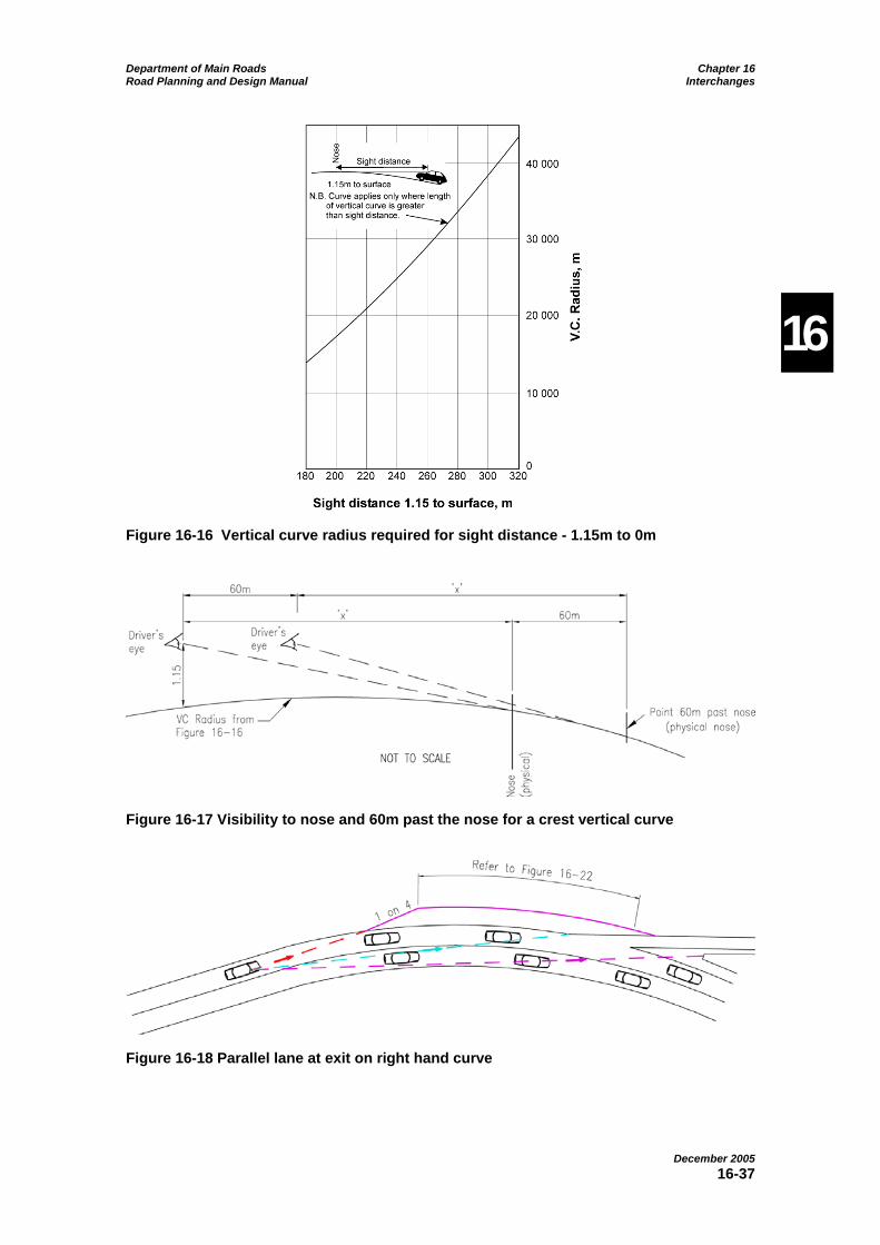
Department of Main Roads Chapter 16 Road Planning and Design Manual Interchanges
December 2005 16-37
16
Figure 16-16 Vertical curve radius required for sight distance - 1.15m to 0m
Figure 16-17 Visibility to nose and 60m past the nose for a crest vertical curve
Figure 16-18 Parallel lane at exit on right hand curve

Department of Main Roads Chapter 16 Road Planning and Design Manual Interchanges
December 2005 16-38
16
If the alignment cannot be changed, a possible solution is to provide a parallel lane as shown in Figure 16-18 (refer also to the preferred single lane exit layout and the double lane exit layout shown in Figure 16-22). This provides an additional visual cue to the presence of the terminal and is less likely to lead a vehicle inadvertently off the through road. The parallel lane treatment also provides greater scope to make the necessary reverse curve manoeuvre compared with the scope available on a taper-only type terminal.
At entry ramp merges, it is necessary for drivers on each carriageway to be able to see the pending merge followed by the need to have mutual visibility between vehicles on the ramp and vehicles on the through-lanes and the need to be able to see the far end (or terminal) of the merge.
With respect to sight distance on the approach, drivers on the ramp need to see in advance where they will have to start looking for vehicles on the through road. Drivers in the through-lanes initially need to able to see that there is likely to be entering traffic and not just rely upon signs for this. This gives drivers in the left lane the chance to decide to change lanes to avoid possible impedance from entering traffic. Drivers in the adjacent through-lanes need to be aware of possible lane changes by vehicles in the left lane and possible impedance from the entering vehicles and vehicles changing from the left lane.
Closer to the merge, but still prior to where any merging or lane changing may occur, mutual visibility allows drivers on the ramp to detect gaps in the traffic in the left
through-lane and judge vehicle speeds. Drivers in the left through lane are able to see entering vehicles and may have to adjust speed accordingly.
Before the end of any merge, drivers need to be able see the end and take appropriate action. The design domain for approach visibility, mutual visibility and terminal visibility at merges is given in Table 16-5. Note that no differentiation is made between ramps (Figure 16-21 and Figure 16-22) and merges of major roads (Figure 16-25). The higher volumes associated with the latter are assumed to be compensated by the fact that the right hand lane from the left approach leg does not have to merge with the left lane from the right approach leg.
If possible, the standard for high speed motorways (≥90km/h) should be adopted to allow for future upgrading of the road.
These sight distance requirements have the following implications:
• where the secondary road is over the motorway, the motorway alignment should be relatively straight to avoid having to lengthen the bridge, which increases the structural cost;
• where the motorway is over the secondary road, the entry ramp should be moved further downstream in preference to widening the structure;
• the last 60m of the entry ramp before the nose, is to be graded so that the right edge of the ramp is within 0.6m of the level of the left motorway traffic lane (Vicroads, 1998.)

Department of Main Roads Chapter 16 Road Planning and Design Manual Interchanges
December 2005 16-39
16
Table 16-5 Visibility requirements at entry ramp merges & merges of major roads
Visibility Requirement Design
Domain Approach to nose Mutual visibility between
carriageways Terminal visibility
Desirable lower bound
6s of travel at respective operating speeds on each carriageway prior to nose (1.15m eye height to 0.1m object height)
4s of travel at respective operating speeds on each carriageway prior to point where merging lanes are separated by 2m (1.15m eye height to 1.15m eye height)
6s of travel at operating speed to any point on merge taper2 (1.15m eye height to 0.0m object)
Absolute lower bound
4s of travel at respective operating speeds on each carriageway prior to nose (1.15m eye height to 0.1m object height)
4s of travel at respective operating speeds on each carriageway prior to point where merging lanes are separated by 1m1 (1.15m eye height to 1.15m eye height)
6s of travel at operating speed to any point on merge taper2 (1.15m eye height to 0.0m object)
Notes: 1. Only for tunnels and low speed non-motorway interchanges. 2. In practice, this means:
a. all of a taper type merge has to be seen prior to the nose; and b. most of the parallel lane of a parallel type merge will be seen from the nose.
Where an entry ramp coincides with a left-hand curve, designers should be aware that:
• curves requiring greater than the maximum desirable “f” value must not be used as they can inhibit vehicle control (true for both right-hand and left-hand curves);
• it is difficult for an entering driver on the ramp to see approaching vehicles on the motorway because of the observation angle;
• it is difficult for the entering driver to judge the length of approaching multi-combination vehicles; and
• approaching vehicles on the motorway can be in the blind spot of entering trucks.
A possible solution is to provide a parallel lane as it gives drivers of entering vehicles more room and time to decide what to do (Figure 16-21).
Designers must also be aware of the potential sight distance problems on roundabout interchanges where bridge parapets occur. The height of the parapets has increased over time and could interrupt the sight line for drivers.
Visualisation aids can be useful for designers in reviewing sight distance requirements on all elements of the design.
16.5.8.4 Alignment
Major road alignment – horizontal and vertical
The major road alignment in the vicinity of an interchange should be as close to straight as possible in the horizontal and vertical planes to ensure that the sight distance requirements to the noses of ramps are met.
Chapter 4 sets out the design principles and guidelines for roads performing a motorway function.
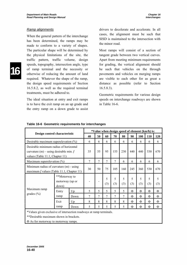
Department of Main Roads Chapter 16 Road Planning and Design Manual Interchanges
December 2005 16-40
16
Ramp alignments
When the general pattern of the interchange has been determined, the ramps may be made to conform to a variety of shapes. The particular shape will be determined by the physical limitations of the site, the traffic pattern, traffic volume, design speeds, topography, intersection angle, type of ramp terminal and the necessity or otherwise of reducing the amount of land required. Whatever the shape of the ramp, the design speed requirements of Section 16.5.8.2, as well as the required terminal treatments, must be adhered to.
The ideal situation at entry and exit ramps is to have the exit ramp on an up grade and the entry ramp on a down grade to assist
drivers to decelerate and accelerate. In all cases, the alignment must be such that SISD is maintained to the intersection with the minor road.
Most ramps will consist of a section of tangent grade between two vertical curves. Apart from meeting minimum requirements for grading, the vertical alignment should be such that vehicles on the through pavements and vehicles on merging ramps are visible to each other for as great a distance as possible (refer to Section 16.5.8.3).
Geometric requirements for various design speeds on interchange roadways are shown in Table 16-6.
Table 16-6 Geometric requirements for interchanges
*Value when design speed of element (km/h) is: Design control characteristic
40 50 60 70 80 90 100 110 120 Desirable maximum superelevation (%) 6 6 6 6 6 6 6 6 6
Desirable minimum radius of horizontal curvature (m) – using desirable min. f values (Table 11.1, Chapter 11)
35 55 95 155 230 440 440 530 670
Maximum superelevation (%) 7 7 7 7 6 6 6 6 6
Minimum radius of curvature (m) - using maximum f values (Table 11.1, Chapter 11)
30 50 75 105 160 245 360 530 670
**Motorway to motorway (up or down)
- - 5
(3) 5
(3) 5
(3) 5
(3) 5
(3) 5
(3) 5
(3)
Up 5 5 5 5 5 Ф Ф Ф Ф Entry ramp Down 7 7 7 7 7 Ф Ф Ф Ф
Up 8 8 8 8 8 Ф Ф Ф Ф
Maximum ramp grades (%)
Exit ramp Down 5 5 5 5 5 Ф Ф Ф Ф
*Values given exclusive of intersection roadways at ramp terminals. **Desirable maximum shown in brackets. Ф As for motorway to motorway ramps.

Department of Main Roads Chapter 16 Road Planning and Design Manual Interchanges
December 2005 16-41
16
Ramp grades should be as flat as feasible to minimise the driving effort required. Since slowing down on ascending ramps is not as serious as on the through roadway, grades entry ramps can be steeper than those on the through road.
The actual grade adopted will be the result of a balance between the length of ramp, the vertical curve requirements at the terminals and the potential operating difficulties that may occur on the grades.
In general, providing adequate sight distance is more important than a specific grade control. However, some limits can be placed on the maximum grades to be used.
Maximum grades on motorway interchange ramps are based on the ability of a heavy vehicle to enter or leave high speed traffic at the operating speed at the nose, and in the case of an exit ramp to allow that vehicle to safely negotiate the ramp geometry. Lower speed interchanges which will be required to accept a higher degree of interruption to flow can accept steeper grading on both exit and entry connections. Local limits in each situation should be based on acceleration/deceleration criteria.
Some examples of grading issues at diamond interchanges are shown in Figure 16-19.
Vertical curvature must be designed in accordance with the principles of Chapter 12.
Horizontal curvature must be designed in accordance with the principles of Chapter 11.
Minor Road Alignment
Where the minor road passes over the major road, it should be as straight as possible and square to the alignment of the major road. This is because:
• curved structures cost more than straight ones;
• curved bridges (particularly box girders) cost more to widen than straight ones;
• the horizontal curvature restricts sight distance from the exit ramp across the structure on the inside of the curve – this can require the structure to be widened;
• superelevation on the bridge can adversely affect sight distance from one of the ramps; and
• skew bridges cost more than square ones.
The problems are not as great if the minor road passes under the major road, provided that adequate sight distance is achieved at the ramp terminals. Safe Intersection Sight Distance (SISD) is required (refer to Chapter 13).
Further, for close diamonds, the bridge parapets and safety barrier may adversely affect the SISD for both of the ramp terminals. The parapets and safety barrier may have to be set back (including appropriate bridge widening) to achieve the required sight distance. Alternatively, the location of the intersections may have to be changed.
On simple diamond interchanges (Figure 16-32) where the minor road is a two-way two-lane road passing over the major road, medians are developed on the minor road at the ramp terminals (or intersections) on the minor road to provide for protected right turns or roundabouts. Deviation of the minor road alignment is required to accommodate these medians.
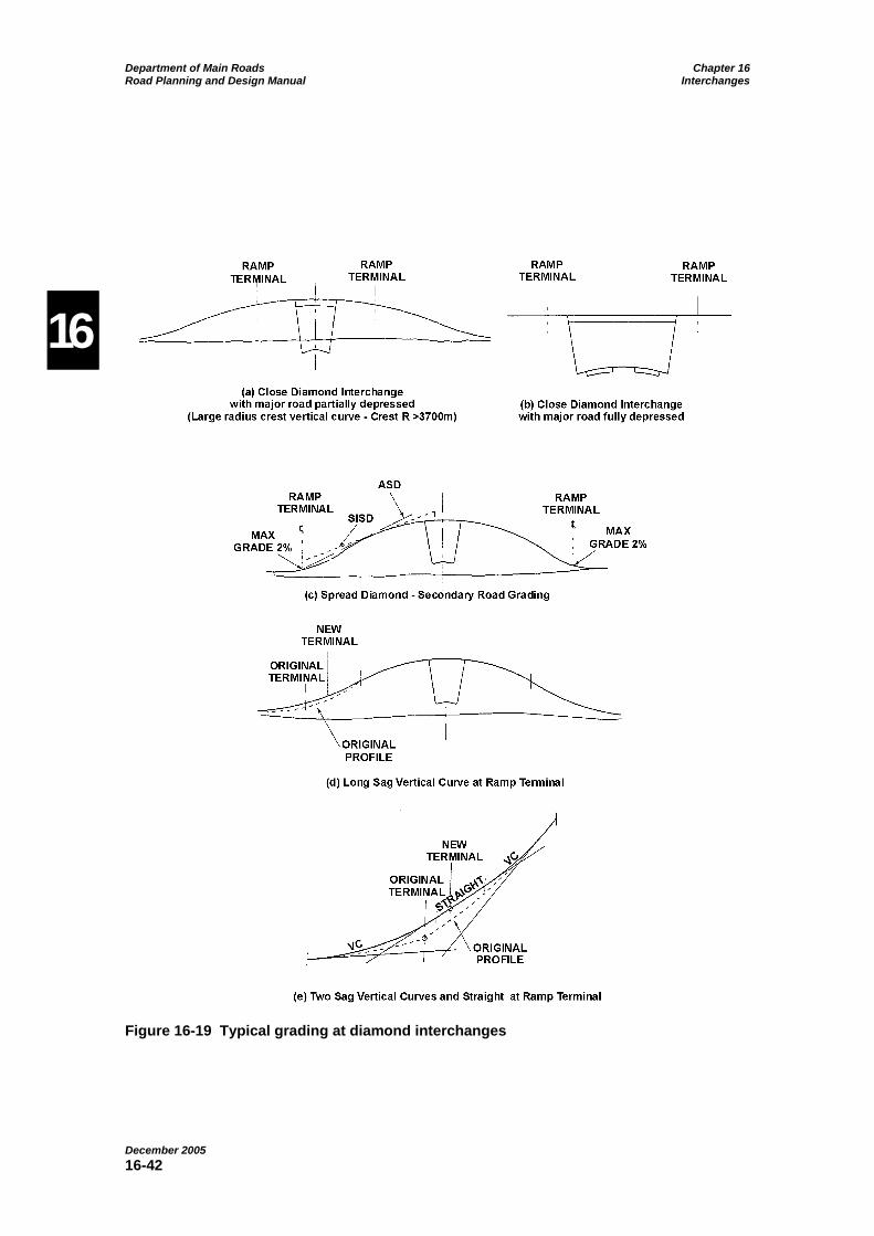
Department of Main Roads Chapter 16 Road Planning and Design Manual Interchanges
December 2005 16-42
16
Figure 16-19 Typical grading at diamond interchanges

Department of Main Roads Chapter 16 Road Planning and Design Manual Interchanges
December 2005 16-43
16
Figure 16-20 Alignment of minor road traffic lanes - spread diamond
Figure 16-20 illustrates two alternative approaches to this problem. Note that:
• In Alternative (a) (Figure 16-20) the alignment deviates on the approach side of the structure where it is clearly visible to the driver.
• Alternative (b) (Figure 16-20) spreads the deviation so that about half of the required lateral movement is achieved on each side of the structure.
Horizontal curves used on the departure side of the structure should have a radius of at least 3,000m. On the approach side the horizontal curves must be appropriate for the relevant operating speed. Alternative (b) (Figure 16-20) allows the spread to be achieved in a much smaller distance but must not be used as a means of reducing the distance between the structure and the ramp terminal.
It is not acceptable to provide a straight alignment on the approaches to and across the structure and deviate the alignment by a full lane width on the far side of the bridge (Vicroads, 1998).
16.5.8.5 Ramp cross section
Pavement and shoulder widths are given in Table 16-7. Shoulders must be paved full depth and sealed. Where it is practicable, shoulders with colour and/or texture differing from the pavement provide a useful contrast and help to prevent traffic usage of the shoulder. Audible edge lines may have a similar effect.
Table 16-7 Ramps - lane and shoulder widths
Shoulder width (m)
Number of lanes on the
ramp
*Lane width (m)
Left Right 1 4.0 2.0 1.0
2 3.5 2.0 1.0
2 for length of ramp (refer to
Section 16.5.8.1)
3.5 1.0 1.0
3 3.7 middle 3.5 outer
2.0 1.0
*Plus curve widening where applicable on turning roadways.

Department of Main Roads Chapter 16 Road Planning and Design Manual Interchanges
December 2005 16-44
16
On loops designed for one lane of traffic, curve widening may be required to allow for the tracking of the design vehicle. For two lane loops, the lane widths must allow for a semi-trailer and a car to travel side by side.
Crossfalls and batter slopes are discussed in Chapter 7.
Kerbs
Kerbs are not to be used on diverge or exit noses on interchanges where the operating speed of the through roadway is 80km/h or greater, but may be used on low speed interchange roadways to:
• delineate edges;
• control pavement drainage;
• restrain undesirable traffic movement; and
• improve the roadway appearance.
However, irrespective of the above, using kerbs on loops should be avoided as any impact of the tyres with the kerb can destabilise and roll a semi-trailer. Barrier kerb must not be used within the interchange particularly on loops. If semi-mountable kerb is used on the outside of loops, the shoulder must be at least 2.0m wide.
Details of the standard kerb shapes and their uses are provided in Chapter 7.
16.5.8.6 Ramp terminals
Through pavement entry and exit ramp terminals
The efficiency of the through road operation and the capacity of the ramps depend largely on the through pavement to ramp terminal design. The ease with which vehicles can enter or leave the through
traffic lanes will determine the traffic flow characteristics in the interchange area.
Good design practice ensures that vehicles can decelerate and accelerate without impeding through traffic. In addition, the ramp length and number of lanes on the ramp must be such as to ensure that queued vehicles will not impede through traffic.
Details of the dimensions to be adopted for ramps are shown in Figure 16-21, Figure 16-22, Figure 16-23, Figure 16-24 and Figure 16-25 for high-speed operation.
The entrance to the motorway for high speed conditions is based on providing drivers with an opportunity to merge after reaching the motorway road speed. A parallel lane adjacent to the through lanes should generally be used to assist the merge operation, both from a capacity and a safety point of view, especially at high traffic volumes. Table 16-8 sets out the length of the parallel lane for various conditions.
Drivers will merge as gaps become available and do not necessarily follow the taper.
A different mode of operation applies in Figure 16-25 where merging of two high speed roads occurs. In this case, the two roadways meet tangentially instead of at a slight angle as with a ramp (1:50). The angle associated with the ramp is intended to provide a cue for a pending lane change.
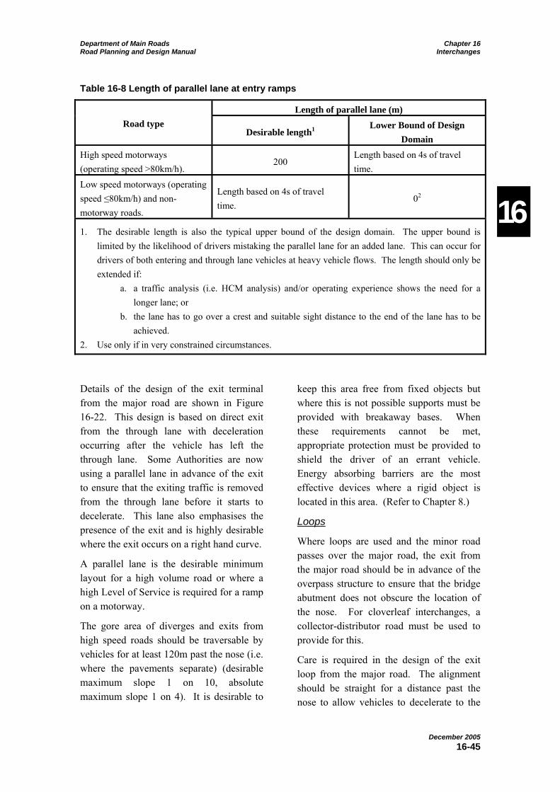
Department of Main Roads Chapter 16 Road Planning and Design Manual Interchanges
December 2005 16-45
16
Table 16-8 Length of parallel lane at entry ramps
Length of parallel lane (m) Road type
Desirable length1 Lower Bound of Design
Domain High speed motorways (operating speed >80km/h).
200 Length based on 4s of travel time.
Low speed motorways (operating speed ≤80km/h) and non-motorway roads.
Length based on 4s of travel time.
02
1. The desirable length is also the typical upper bound of the design domain. The upper bound is limited by the likelihood of drivers mistaking the parallel lane for an added lane. This can occur for drivers of both entering and through lane vehicles at heavy vehicle flows. The length should only be extended if:
a. a traffic analysis (i.e. HCM analysis) and/or operating experience shows the need for a longer lane; or
b. the lane has to go over a crest and suitable sight distance to the end of the lane has to be achieved.
2. Use only if in very constrained circumstances.
Details of the design of the exit terminal from the major road are shown in Figure 16-22. This design is based on direct exit from the through lane with deceleration occurring after the vehicle has left the through lane. Some Authorities are now using a parallel lane in advance of the exit to ensure that the exiting traffic is removed from the through lane before it starts to decelerate. This lane also emphasises the presence of the exit and is highly desirable where the exit occurs on a right hand curve.
A parallel lane is the desirable minimum layout for a high volume road or where a high Level of Service is required for a ramp on a motorway.
The gore area of diverges and exits from high speed roads should be traversable by vehicles for at least 120m past the nose (i.e. where the pavements separate) (desirable maximum slope 1 on 10, absolute maximum slope 1 on 4). It is desirable to
keep this area free from fixed objects but where this is not possible supports must be provided with breakaway bases. When these requirements cannot be met, appropriate protection must be provided to shield the driver of an errant vehicle. Energy absorbing barriers are the most effective devices where a rigid object is located in this area. (Refer to Chapter 8.)
Loops
Where loops are used and the minor road passes over the major road, the exit from the major road should be in advance of the overpass structure to ensure that the bridge abutment does not obscure the location of the nose. For cloverleaf interchanges, a collector-distributor road must be used to provide for this.
Care is required in the design of the exit loop from the major road. The alignment should be straight for a distance past the nose to allow vehicles to decelerate to the

Department of Main Roads Chapter 16 Road Planning and Design Manual Interchanges
December 2005 16-46
16
operating speed of the loop (refer to Figure 16-22 for deceleration distances). Where feasible, an alternative treatment is to provide a series of speed reduction curves to produce the desired result (refer to Example 16C, Appendix 16C).
Drivers must be able to estimate the safe speed of the loop and therefore need adequate sight distance as well as visual cues to do this. Drivers must be able to see an adequate length of pavement on the curve of the loop (about 5° field of view). For downhill loops, this will not be possible and other cues such as high fencing beyond the clear zone will be required to delineate its shape and location.
When spirals are present on the loop curve, drivers tend to overestimate the safe speed of the curve. Therefore, spirals are not to be used on the approaches to loop ramps.
This will usually require the use of reverse curves on the approaches to the loop (or alternative treatments) as discussed in Section 16.5.8.2 and Appendix 16C, designed so that the combination of operating speed, radius and superelevation for the loop curve does not require a transition curve (refer to Chapter 11). The minimum radius for an exit ramp loop is 55m but loops of radius greater than 80m are not generally used since the faster speed around the loop is negated by the extra distance travelled. An increase in design speed of 8km/h on the loop increases the travel distance by more than 50%. Further, the larger radius results in a significantly greater land requirement for the interchange.
Because of the significant difference in speed of the through road and the loop, drivers may approach the curve of the loop at too great a speed. Loss of control can occur and is most likely in the first 80m of
the loop. A “run out” area should be provided around the outside of the loop as shown in Figure 16-26 and should be free of obstructions and hazards. If a driveable area cannot be provided as shown, road safety barrier is to be installed around the outside of the curve.
For entry loops, the minimum radius should be 55m but in urban areas in confined conditions, radii as low as 30m can be used provided the maximum grade criteria are met. If the exit speed from the minor road exceeds 60km/h, the layout of the approach to the loop should be similar to that in Figure 16-26 but oriented to the minor road.
Merge areas
An emergency run out area is to be provided in all merge areas. This is achieved by continuing the pavement edge parallel to the centre line from the start of the taper to create a wider shoulder over the length of the taper plus a distance of 30m beyond the end of the taper (refer to Chapter 15, Figure 15.6 and Figure 16-7).
Low speed major road
Interchanges are sometimes provided on non-motorway roads and some motorway standard roads are designed for low speed (≤ 80km/h) operation. Table 16-8 provides details of lengths of parallel lanes. Figure 16-23 shows an arrangement of an interchange in a very constrained situation (i.e. no parallel lane). A suitable run-out area at the end of the taper will be required (refer to Figure 16-7) if shoulders are less than 2.5m wide.
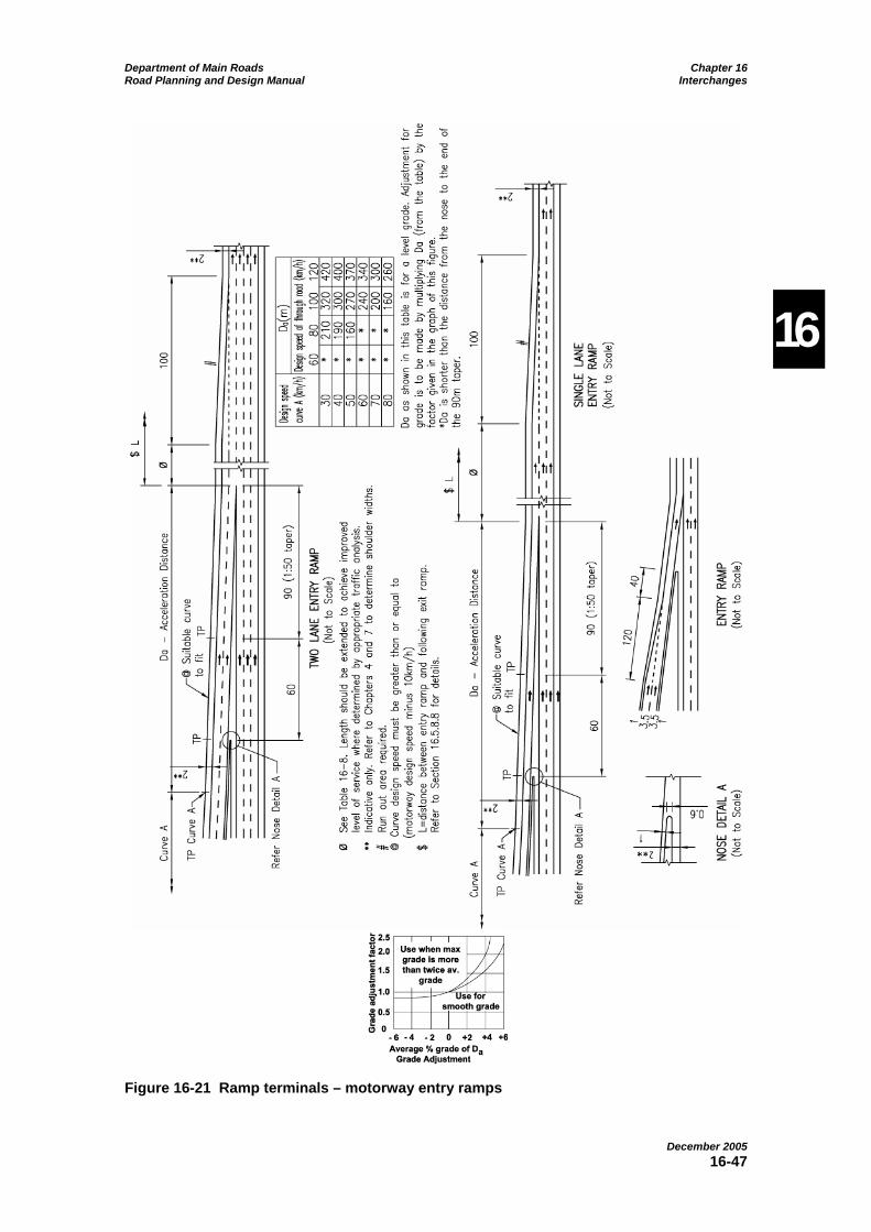
Department of Main Roads Chapter 16 Road Planning and Design Manual Interchanges
December 2005 16-47
16
Figure 16-21 Ramp terminals – motorway entry ramps

Department of Main Roads Chapter 16 Road Planning and Design Manual Interchanges
December 2005 16-48
16
Figure 16-22 Ramp terminals – motorway exit ramps
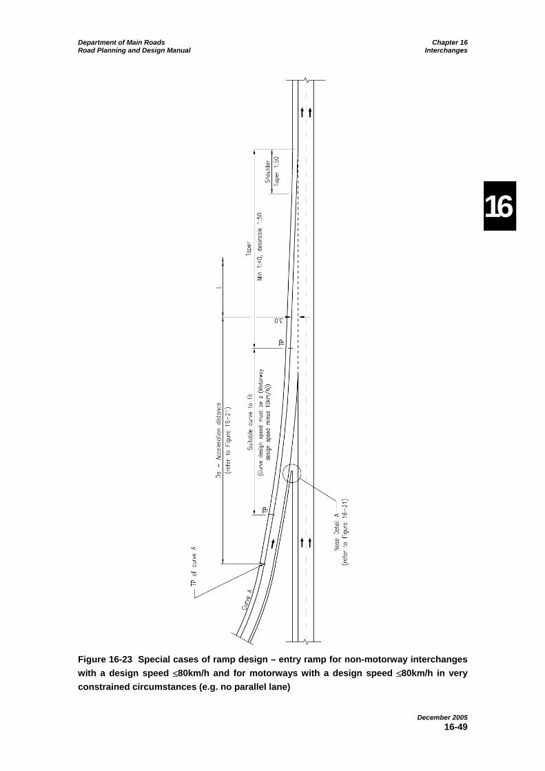
Department of Main Roads Chapter 16 Road Planning and Design Manual Interchanges
December 2005 16-49
16
Figure 16-23 Special cases of ramp design – entry ramp for non-motorway interchanges with a design speed [80km/h and for motorways with a design speed [80km/h in very constrained circumstances (e.g. no parallel lane)

Department of Main Roads Chapter 16 Road Planning and Design Manual Interchanges
December 2005 16-50
16
Figure 16-24 Special cases of ramp design – two-lane two-way motorways (staged construction)

Department of Main Roads Chapter 16 Road Planning and Design Manual Interchanges
December 2005 16-51
16
Figure 16-25 Major turning movements - merge and diverge details
Figure 16-26 Run-out area around an exit loop
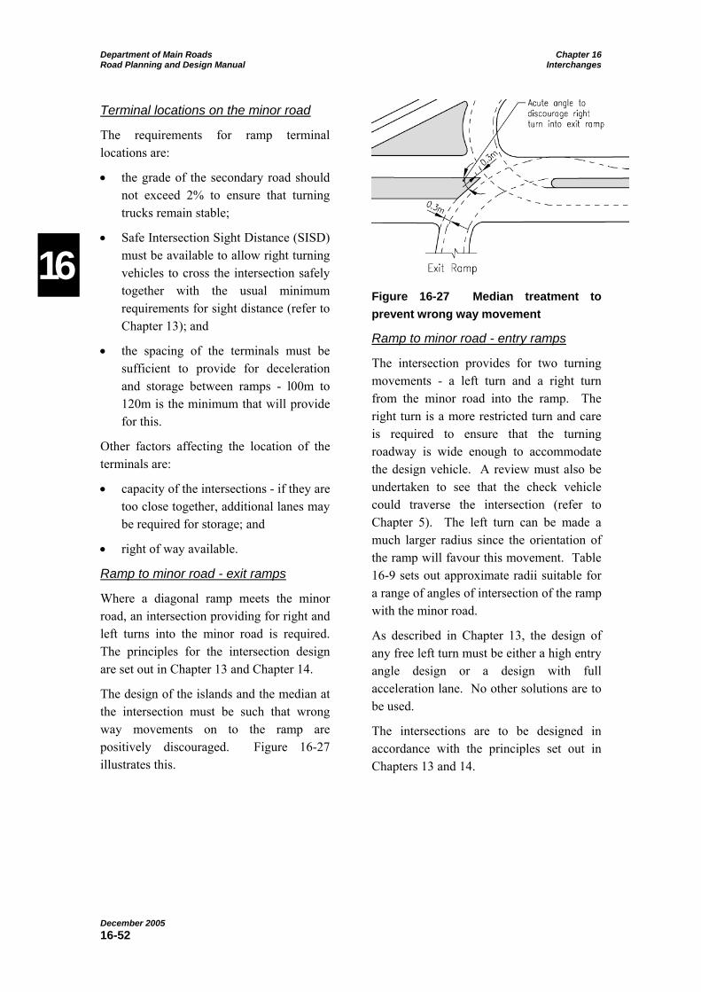
Department of Main Roads Chapter 16 Road Planning and Design Manual Interchanges
December 2005 16-52
16
Terminal locations on the minor road
The requirements for ramp terminal locations are:
• the grade of the secondary road should not exceed 2% to ensure that turning trucks remain stable;
• Safe Intersection Sight Distance (SISD) must be available to allow right turning vehicles to cross the intersection safely together with the usual minimum requirements for sight distance (refer to Chapter 13); and
• the spacing of the terminals must be sufficient to provide for deceleration and storage between ramps - l00m to 120m is the minimum that will provide for this.
Other factors affecting the location of the terminals are:
• capacity of the intersections - if they are too close together, additional lanes may be required for storage; and
• right of way available.
Ramp to minor road - exit ramps
Where a diagonal ramp meets the minor road, an intersection providing for right and left turns into the minor road is required. The principles for the intersection design are set out in Chapter 13 and Chapter 14.
The design of the islands and the median at the intersection must be such that wrong way movements on to the ramp are positively discouraged. Figure 16-27 illustrates this.
Figure 16-27 Median treatment to prevent wrong way movement
Ramp to minor road - entry ramps
The intersection provides for two turning movements - a left turn and a right turn from the minor road into the ramp. The right turn is a more restricted turn and care is required to ensure that the turning roadway is wide enough to accommodate the design vehicle. A review must also be undertaken to see that the check vehicle could traverse the intersection (refer to Chapter 5). The left turn can be made a much larger radius since the orientation of the ramp will favour this movement. Table 16-9 sets out approximate radii suitable for a range of angles of intersection of the ramp with the minor road.
As described in Chapter 13, the design of any free left turn must be either a high entry angle design or a design with full acceleration lane. No other solutions are to be used.
The intersections are to be designed in accordance with the principles set out in Chapters 13 and 14.
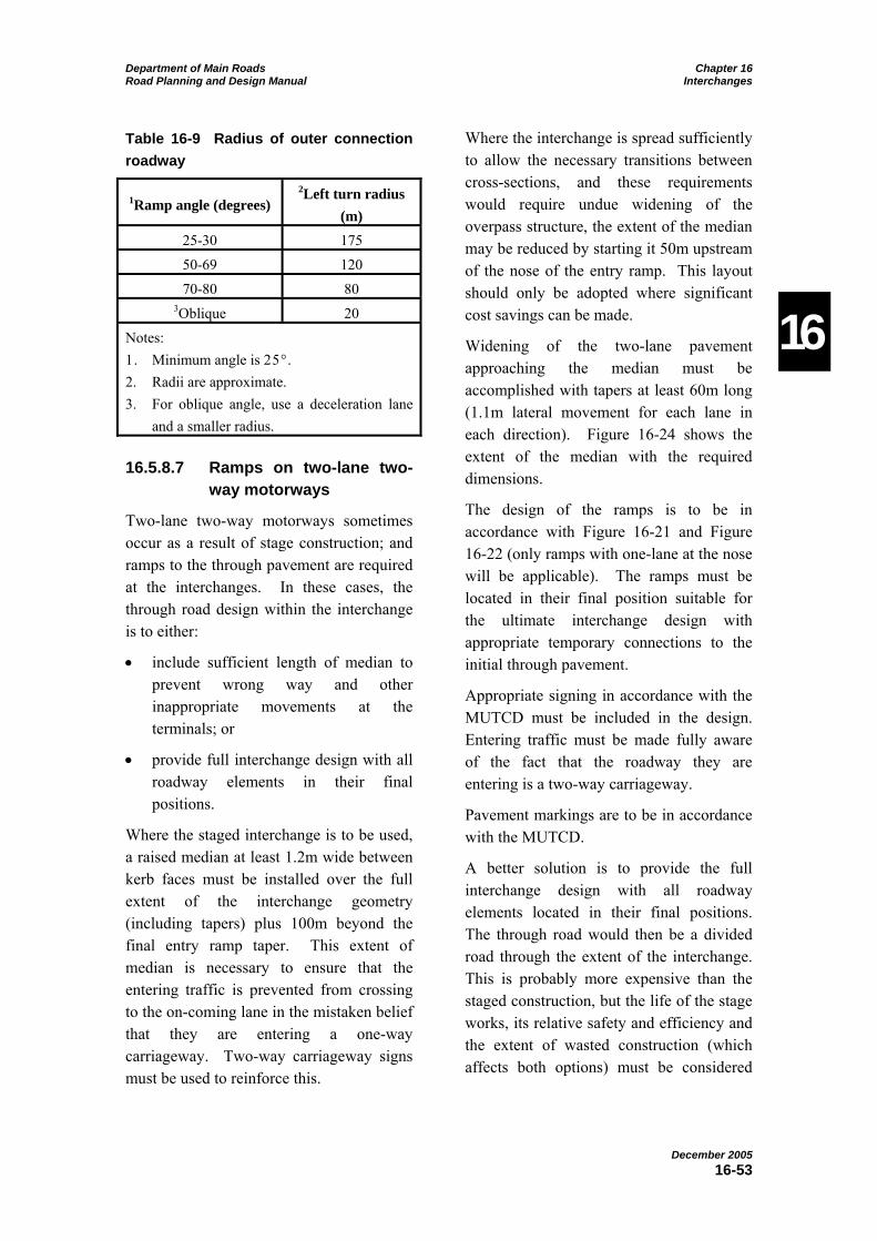
Department of Main Roads Chapter 16 Road Planning and Design Manual Interchanges
December 2005 16-53
16
Table 16-9 Radius of outer connection roadway
1Ramp angle (degrees) 2Left turn radius
(m) 25-30 175
50-69 120
70-80 80 3Oblique 20
Notes: 1. Minimum angle is 25°. 2. Radii are approximate. 3. For oblique angle, use a deceleration lane
and a smaller radius.
16.5.8.7 Ramps on two-lane two-way motorways
Two-lane two-way motorways sometimes occur as a result of stage construction; and ramps to the through pavement are required at the interchanges. In these cases, the through road design within the interchange is to either:
• include sufficient length of median to prevent wrong way and other inappropriate movements at the terminals; or
• provide full interchange design with all roadway elements in their final positions.
Where the staged interchange is to be used, a raised median at least 1.2m wide between kerb faces must be installed over the full extent of the interchange geometry (including tapers) plus 100m beyond the final entry ramp taper. This extent of median is necessary to ensure that the entering traffic is prevented from crossing to the on-coming lane in the mistaken belief that they are entering a one-way carriageway. Two-way carriageway signs must be used to reinforce this.
Where the interchange is spread sufficiently to allow the necessary transitions between cross-sections, and these requirements would require undue widening of the overpass structure, the extent of the median may be reduced by starting it 50m upstream of the nose of the entry ramp. This layout should only be adopted where significant cost savings can be made.
Widening of the two-lane pavement approaching the median must be accomplished with tapers at least 60m long (1.1m lateral movement for each lane in each direction). Figure 16-24 shows the extent of the median with the required dimensions.
The design of the ramps is to be in accordance with Figure 16-21 and Figure 16-22 (only ramps with one-lane at the nose will be applicable). The ramps must be located in their final position suitable for the ultimate interchange design with appropriate temporary connections to the initial through pavement.
Appropriate signing in accordance with the MUTCD must be included in the design. Entering traffic must be made fully aware of the fact that the roadway they are entering is a two-way carriageway.
Pavement markings are to be in accordance with the MUTCD.
A better solution is to provide the full interchange design with all roadway elements located in their final positions. The through road would then be a divided road through the extent of the interchange. This is probably more expensive than the staged construction, but the life of the stage works, its relative safety and efficiency and the extent of wasted construction (which affects both options) must be considered

Department of Main Roads Chapter 16 Road Planning and Design Manual Interchanges
December 2005 16-54
16
before adopting the two-lane two-way through pavement through the interchange.
16.5.8.8 Distance between ramp terminals
The spacing of ramp terminals is the most significant factor in determining the operating characteristics of a motorway. Each exit and entry ramp terminal creates some level of turbulence in the traffic stream on each side of the exit or entry point. The extent of this disturbance is approximately:
• 450m upstream from the exit point of the exit ramp in the two through lanes closest to the exit ramp; and
• 450m downstream of the entry point of the entry ramp in the two through lanes closest to the exit ramp.
In addition to this disturbance, drivers need a significant distance to change lanes to position themselves for the exit manoeuvre after they recognise the need to do so following the appropriate signage.
In those cases where an entry is followed by an exit, a weaving section will be created if the points of entry and exit of the ramps are sufficiently close. This introduces an additional disturbance to the traffic stream as well as increasing the hazard to drivers.
Weaving is a complex traffic flow issue and requires careful analysis where it occurs and a full discussion of weaving analysis is beyond the scope of this Manual. Designers must refer to the HCM (TRB, 2000) which sets out the methodology for analysing weaving sections of up to approximately 750m in length. Weaving segments longer than 750m are treated as isolated merge and diverge areas using the procedures for those manoeuvres.
Where practicable and affordable, the preferred location for weaving sections is on collector-distributor roads, which operate at lower speeds, rather than the through carriageways.
Table 16-10 provides the minimum spacings for the different entry/exit ramp terminal combinations. Greater spacings are always preferred, and the proposed spacing must always be checked in accordance with the procedures outlined in the HCM and increased if necessary to produce a consistent level of service for the overall road link.
Conditions in both peak and off-peak conditions are to be analysed to ensure that the level of service is consistent within each period. The actual level of service will not be the same for both situations as it is expected that the level of service will be lower in peak conditions.
It is important for off-peak operation to maintain the operating speed through the section to minimise speed differentials in the interests of safer operation.
16.5.8.9 Major forks
A major fork is the split of a directional roadway or of a terminating major road route into two directional ramps connecting to another major road; or the diverging area created by the separation of a major route into two separate major routes of about equal importance. They often occur in major road to major road interchanges such as Y and T interchanges.
Figure 16-28 illustrates two examples of major fork design together with design details.

Department of Main Roads Chapter 16 Road Planning and Design Manual Interchanges
December 2005 16-55
16
Table 16-10 Distances between points – entry and exit ramp terminals
1Configuration 1Type of carriageway 1,3Desirable
(m) 1,3Minimum
(m)
Motorway - 3007
Successive exits (i.e. exit followed by exit) or successive entrances (i.e. entry followed by entry)2
Service Road or Collector-Distributor
Road - 2407
Motorway - 1507 Exit followed by entrance
Service Road or Collector-Distributor
Road - 1207
System Interchange - 2407
Successive exits or successive entries on connecting roads (or turning roadways, i.e. distance between terminals within interchange itself).
Service Interchange - 1807
2 lanes 9004,6 -6
3 lanes 12006 -6
Entrance followed by exit6 4 lanes 15005,6 -6
Notes: 1. This table is a guide only. All configurations must be analysed in accordance with the HCM (TRB,
2000). The distance/s (i.e. “L”) must be increased where required to achieve the design level of service (analysed using the HCM) or to achieve a consistent level of service along the link. The distances given do not apply to major forks or merges. In determining the required spacing the number of lanes in the ultimate stage of the motorway must be used.
2. Not a preferred configuration for a motorway. 3. It is preferable for the distances to be greater than the minimum to provide drivers with more decision
making time. 4. Based on providing no overlapping areas of turbulence. 5. Based on signage and lane changing requirements of a four lane motorway carriageway. 6. Figure 16-21, Figure 16-22, Figure 16-23 and Figure 16-24 indicate the points between which the
distance “L” is to be measured. Dimensions less than the desirable must be justified by a complete analysis undertaken in accordance with the HCM. Notwithstanding this table or the HCM analysis, it is desirable that not less than 4s of travel, at the desired speed of the major road, be provided between the end of the last taper of the entry terminal and the start of the first taper of the following exit terminal.
7. The distance “L” is measured from like point to like point. This length is subject to signage requirements (i.e. length may need to be increased so that the motorway and ramps can be signed adequately [e.g. to provide sufficient distance between signs or between sign and exit/entry]) and a HCM analysis (as per Note 1 of this table.)
L
L
L
L
L
L

Department of Main Roads Chapter 16 Road Planning and Design Manual Interchanges
December 2005 16-56
16
Figure 16-28 Major forks

Department of Main Roads Chapter 16 Road Planning and Design Manual Interchanges
December 2005 16-57
16
Direct right hand exits are to be used when the traffic in that direction exceeds 50% of the through traffic. If the right turning traffic is less than 30% of the total, a normal exit to the left is to be used. For right turning traffic between 30% and 50%, the decision on whether the right turning traffic is to depart from the traffic stream on the left or the right has to take account of route continuity considerations. The divergence should be treated as a major fork regardless of the orientation of the two legs of the fork after the divergence.
The layouts shown in Figure 16-28 have the appropriate lane balance in which the number of lanes downstream of the split is one more than the total approaching the split. The central lane (or at least one of the central lanes) must allow the traffic in that lane to choose which direction to take. If this is not done operational difficulties will occur (AASHTO, 2001).
The operating conditions at locations of major forks are different from those at other interchanges and some stringent controls are required to ensure their safe operation, including the following:
• The approach to the nose should be straight or nearly so.
• Long sight distances should be provided both on the approach to the gore area and to all signs to allow drivers adequate time to assess the situation and take the appropriate action. It must be remembered that some drivers may have to change lanes to position themselves for the correct roadway. Sight distance to the nose is to be at least 440m measured from an eye height of 1.15m to zero object height.
• Gantry signs should be used to ensure that drivers know which lane to enter (gantry supports are not to be placed in the gore).
Downstream of the fork, the speeds on the two roadways must be consistent with the operating speed on the major road. Depending on the geometry possible, speed drops of 10km/h are acceptable provided the diverging roadways are clearly visible to the driver.
For those cases where the turning traffic is less than 30% of the total, the turning roadway can be designed as a normal ramp. The major movement would appear as a continuation of the major road proper (refer to Figure 16-28(e)).
The turning roadways in both of the above cases must have at least two lanes.
16.5.8.10 Branch connections
A branch connection is defined as the beginning of a carriageway of a major road formed by the convergence of two directional multi-lane ramps from another major road, or by the convergence of two motorway routes to form a single motorway route.
These connections often form part of system interchanges. Figure 16-29 shows two possible branch connections.

Department of Main Roads Chapter 16 Road Planning and Design Manual Interchanges
December 2005 16-58
16
Figure 16-29 Branch connections
Figure 16-30 Branch connection details (Vicroads, 1998)
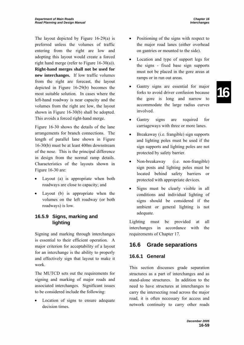
Department of Main Roads Chapter 16 Road Planning and Design Manual Interchanges
December 2005 16-59
16
The layout depicted by Figure 16-29(a) is preferred unless the volumes of traffic entering from the right are low and adopting this layout would create a forced right hand merge (refer to Figure 16-30(a)). Right-hand merges shall not be used for new interchanges. If low traffic volumes from the right are forecast, the layout depicted in Figure 16-29(b) becomes the most suitable solution. In cases where the left-hand roadway is near capacity and the volumes from the right are low, the layout shown in Figure 16-30(b) shall be adopted. This avoids a forced right-hand merge.
Figure 16-30 shows the details of the lane arrangements for branch connections. The length of parallel lane shown in Figure 16-30(b) must be at least 400m downstream of the nose. This is the principal difference in design from the normal ramp details. Characteristics of the layouts shown in Figure 16-30 are:
• Layout (a) is appropriate when both roadways are close to capacity; and
• Layout (b) is appropriate when the volumes on the left roadway (or both roadways) is low.
16.5.9 Signs, marking and lighting
Signing and marking through interchanges is essential to their efficient operation. A major criterion for acceptability of a layout for an interchange is the ability to properly and effectively sign that layout to make it work.
The MUTCD sets out the requirements for signing and marking of major roads and associated interchanges. Significant issues to be considered include the following:
• Location of signs to ensure adequate decision times.
• Positioning of the signs with respect to the major road lanes (either overhead on gantries or mounted to the side).
• Location and type of support legs for the signs - fixed base sign supports must not be placed in the gore areas at ramps or in run out areas.
• Gantry signs are essential for major forks to avoid driver confusion because the gore is long and narrow to accommodate the large radius curves involved.
• Gantry signs are required for carriageways with three or more lanes.
• Breakaway (i.e. frangible) sign supports and lighting poles must be used if the sign supports and lighting poles are not protected by safety barrier.
• Non-breakaway (i.e. non-frangible) sign posts and lighting poles must be located behind safety barriers or protected with appropriate devices.
• Signs must be clearly visible in all conditions and individual lighting of signs should be considered if the ambient or general lighting is not adequate.
Lighting must be provided at all interchanges in accordance with the requirements of Chapter 17.
16.6 Grade separations
16.6.1 General
This section discusses grade separation structures as a part of interchanges and as stand-alone structures. In addition to the need to have structures at interchanges to carry the intersecting road across the major road, it is often necessary for access and network continuity to carry other roads

Department of Main Roads Chapter 16 Road Planning and Design Manual Interchanges
December 2005 16-60
16
across the major road. The structures will carry either the major road over the intersecting road or the minor road over the major road (refer to Section 16.6.3).
This discussion is confined to the geometric features of structures although many aspects of structural design must be considered (refer to Chapter 22). These are referred to as necessary where they impact on the geometric design but road designers must refer structural matters to specialist bridge engineers.
A grade separation should conform in alignment (both horizontal and vertical) and cross section to the natural lines of the approaches. The structure is to be designed to fit the road, not the road to fit the structure. However, road designers must position roadways carefully to minimise skews and spans to reduce the cost of structures.
16.6.2 Types of structures
“The type of structure best suited to grade separation is one that gives drivers little sense of restriction. Where drivers take practically no notice of the structure over which they are crossing, their behaviour is the same or nearly the same as at other points on the highway, and sudden, erratic changes in speed and direction are unlikely” (AASHTO, 2001).
In the case of structures passing over the road (Figure 16-31), it is impossible to be unaware of their presence. These structures should be designed to fit into the environment in a pleasing way that is not distracting. The best result will be achieved through collaboration with the bridge designer and a landscape architect/urban designer to ensure that the structure meets all requirements.
Figure 16-31 Typical bridges
Department of Main Roads Chapter 16 Road Planning and Design Manual Interchanges
December 2005 16-61
16
Two general types of structure can be built – solid abutment types and open-end span types. Open-end spans are preferred and are to be used unless good reasons can be advanced for the construction of solid abutments (e.g. solid abutments are generally more economical for bridges on large skews, and the presence of more retaining walls in an arterial road interchange may dictate solid abutments).
Structures that pass over a divided road may or may not have central piers in the median. Although it is preferable to have the median free of such an obstruction, both from an aesthetic and safety point of view, economic and practical considerations may prevent this being achieved. When the median requires the installation of continuous safety barrier, there is little point in attempting to dispense with a pier in the median.
16.6.3 Over or under
Whether the major road passes over or under the minor road can be a significant question. In many cases, the topography and the relative grading of the roads will dictate the best result. One of three conditions can arise:
• the influence of the topography dominates and the design is fitted to it;
• the topography does not favour either of the roads; or
• the alignment and grade line controls of one road are sufficiently important to subordinate those of the other.
In general, the design that fits the topography will be the most pleasing and the most economical. If this situation does not prevail, the following factors are to be considered in making the decision on the relative grades of the roads:
• Economy – the alternative arrangements (including the need for earthworks balance) must be investigated to assess whether to go over or under. In general it is more economical to have the major road constructed at the existing ground level and to place the minor road over. This usually results in fewer and smaller bridges, with the additional advantage of better “ride ability” on the major route and fewer interruptions during periods of maintenance.
• Traffic warning – it may be important to alert the driver to the interchange ahead.
• Aesthetics – the through road may be given preference by making it the overpass to take advantage of a vista or to create a feeling of minimum restriction.
• Operations – at interchanges, the operations on the ramps are assisted by having the major road on the lower level. This provides for the exiting traffic to slow down on the up grade and the entering traffic to accelerate on the down grade.
• Sight Distance – in rolling topography, if there is no pronounced advantage in using either an overpass or an underpass, the type that produces the best sight distance for the major road is to be selected.
• Stage construction – an overpass solution offers the best approach to stage construction since the first stage can be built part width as a complete entity. The second stage can be built separate from this structure without any loss in use of the first stage. The length of span must allow for the future

Department of Main Roads Chapter 16 Road Planning and Design Manual Interchanges
December 2005 16-62
16
widening of the road or railway under the structure.
• Drainage – difficult drainage problems can be reduced by carrying the major road over without changing the grade line of the minor road.
• Overall strategy – the grade of the major road may be determined by an overall requirement to have the facility completely depressed or completely elevated.
• Existing traffic – if the new road is to be carried across a heavily trafficked road, an overpass will create the least disruption during construction.
• High loads – on high load routes, an overpass has no limits on vertical clearance and may be the best solution.
• Noise reduction – the road depressed below the surrounding area will have a lower noise impact. The road with the highest traffic will be better placed in this situation in general.
16.6.4 Vertical clearance
The vertical clearances defined in Chapter 7 must be applied. However, very high loads are sometimes moved on the road system and must have a means of traversing the required route. This may be provided by ensuring a suitable by-pass of the limiting structure (by means of ramps at interchanges, for example). For a more detailed discussion, refer to Section 16.3.10.

Department of Main Roads Chapter 16 Road Planning and Design Manual Interchanges
December 2005 16-63
16
References
The treatment of this subject has been necessarily short and has identified the essential requirements of interchange design. Designers are encouraged to seek more detailed explanations in the references cited. These have been the primary sources of information for this Chapter.
AASHTO (2001): A Policy for the Geometric Design of Highways and Streets.
Austroads (2000): Guide to Traffic Engineering Practice Part 14 - Bicycles.
National Association of Australian State Road Authorities (1984): Grade Separated Interchanges - A Design Guide.
Transportation Research Board (TRB) (2000): Highway Capacity Manual.
Queensland Department of Main Roads, (2003): Manual of Uniform Traffic Control Devices.
Queensland Department of Main Roads (2004): Queensland Environmental Legislation Register.
Queensland Department of Main Roads (2004): Main Roads Policy - Cycling on State Controlled Roads, Queensland Department of Main Roads, Brisbane.
Vicroads (1998): Road Design Guidelines Part 5 “Interchanges”.
Relationship to other Chapters
• Chapter 2;
• Chapter 4 deals with the general standards of roads that might require an interchange;
• Chapters 13 and 14 give details of intersection requirements (an essential requirement at interchanges);
• Chapters 5, 6, 7, 8, 9, 15, 17, 19, 20 and 22 also provide input to this Chapter.

Department of Main Roads Chapter 16 Road Planning and Design Manual Interchanges
December 2005 16-64
16
Appendix 16A: Traffic data requirements
The traffic data required for the design of the interchange includes:
• through traffic volumes (including vehicle classifications) - current and design values;
• turning volumes (including the origins and destinations of entering and exiting traffic) - current and design values;
• approach speeds;
• accident rates and types;
• pedestrian and cyclist movements and volumes to be accommodated; and
• public transport movements and volumes - current and design values.
In urban areas, the design volumes will be determined from transport planning studies taking account of land use planning, public transport use, other mode shares and distribution to the overall network of roads. The influence of various transport strategies on the generation and distribution of traffic in the future has to be taken into account in determining the design volume.
It is likely that traffic demand will approach the design levels of service in a short time after opening in urban areas. It is therefore important that the design provide a balanced level of service throughout to avoid “bottleneck” situations developing.
In rural areas, the design is based on an estimated design hourly volume assessed from the traffic patterns peculiar to that road and area. This can vary from the 30th highest hour to the 120th highest hour depending on the type of route. A guide to the most economical design hour can be gained from a plot of the hourly volume
against the number of hours with a volume greater than the ordinate. The resulting graph will usually have two portions – a steep part near the origin, and a flatter part as the number of hours increases. The design hour can then be estimated from the intersection point of the slopes of the two sections of the plot (refer to Chapter 5).
Future volumes can be estimated by simple projection or by modelling. Simple projection may be suitable where growth rates are known and stable and future development is taking a steady path. In other areas, a more comprehensive modelling approach must be adopted to obtain a better insight into the likely future position (refer to Chapter 2).
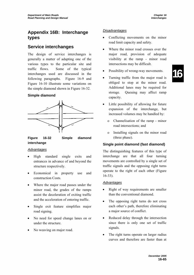
Department of Main Roads Chapter 16 Road Planning and Design Manual Interchanges
December 2005 16-65
16
Appendix 16B: Interchange types
Service interchanges The design of service interchanges is generally a matter of adapting one of the various types to the particular site and traffic flows. Some of the typical interchanges used are discussed in the following paragraphs. Figure 16-9 and Figure 16-10 illustrate some variations on the simple diamond shown in Figure 16-32.
Simple diamond
Figure 16-32 Simple diamond interchange
Advantages
• High standard single exits and entrances in advance of and beyond the structure respectively.
• Economical in property use and construction Costs.
• Where the major road passes under the minor road, the grades of the ramps assist the deceleration of exiting traffic and the acceleration of entering traffic.
• Single exit feature simplifies major road signing.
• No need for speed change lanes on or under the structure.
• No weaving on major road.
Disadvantages
• Conflicting movements on the minor road limit capacity and safety.
• Where the minor road crosses over the major road, provision of adequate visibility at the ramp - minor road intersections may be difficult.
• Possibility of wrong-way movements.
• Turning traffic from the major road is obliged to stop at the minor road. Additional lanes may be required for storage. Queuing may affect ramp capacity.
• Little possibility of allowing for future expansion of the interchange, but increased volumes may be handled by:
o Channelisation of the ramp - minor road intersections; and
o Installing signals on the minor road (three phase).
Single point diamond (fast diamond)
The distinguishing features of this type of interchange are that all four turning movements are controlled by a single set of traffic signals and the opposing right turns operate to the right of each other (Figure 16-33).
Advantages
• Right of way requirements are smaller than the conventional diamond.
• The opposing right turns do not cross each other’s path, therefore eliminating a major source of conflict.
• Reduced delay through the intersection since there is only one set of traffic signals.
• The right turns operate on larger radius curves and therefore are faster than at

Department of Main Roads Chapter 16 Road Planning and Design Manual Interchanges
December 2005 16-66
16
conventional intersections (hence the term “fast diamond”).
• The operational efficiencies result in an interchange with higher capacity than the conventional diamond.
Disadvantages
• Future expansion and staging are very difficult.
• High construction cost associated with the bridge – whether over or under, the size of the structure has to be large.
• The length and geometry of the vehicle path through the intersection can lead to
confusion if adequate guidance is not provided – positive guidance is required (painted lines, raised median, airport runway lights flush with the pavement).
• The potential relative speeds of the vehicles are increased.
• If the intersecting roadways are on a skew, the length of structures required may become excessive, clearance distances are increased and sight distance can be adversely affected.
• Requires traffic signals from the outset.
Figure 16-33 Single point urban interchange (fast diamond)
Parclo A4 (with collector-distributor roads)
A partial cloverleaf interchange with the loop ramp in advance of the overpass structure is known as a Parclo A. If the interchange has ramps in all four quadrants, it becomes a Parclo A4 (Figure 16-34).
Figure 16-34 Parclo A4

Department of Main Roads Chapter 16 Road Planning and Design Manual Interchanges
December 2005 16-67
16
It is preferable that this type of interchange has collector-distributor roads to ensure that there is only one entrance for traffic entering the major road. If collector-distributor roads are not used, the distance between the entrance terminals must be at least 300m (refer to Section 16.5.8.8).
Advantages
• Single exit feature simplifies major road signing.
• No weaving on the major road.
• Not conducive to wrong-way movements.
• Depending on right turn volumes this is a high capacity interchange.
Disadvantages
• The right turn from the ramp to the minor road will require storage on the ramp and additional lanes may be required.
• Signals required on the minor road when the through and turning movements are high.
• Future expansion of the interchange cannot easily be achieved.
• Property and construction costs higher than for a diamond interchange.
Parclo B4 (with collector-distributor roads)
A partial cloverleaf interchange with the loop ramp beyond the overpass structure is known as a Parclo B. If the interchange has ramps in all four quadrants, it is known as a Parclo B4 (Figure 16-35).
Figure 16-35 Parclo B4
This type of interchange must have collector-distributor roads to ensure that there is only one exit from the major road. Providing two exits at an interchange makes it confusing for drivers in deciding where to exit and does not provide for consistency of operation on the facility (refer to Section 16.4).
Advantages
• Single exit feature simplifies signing and promotes consistency of operation.
• No weaving on the major road.
• Not conducive to wrong way movements.
• Depending on right turn movements, this is a high capacity interchange.
Disadvantages
• Property and construction costs higher than for a diamond interchange.
• Signals required on the minor road when through and turning volumes are high (usually in urban areas).
• Right turn movement from the minor road may require storage on or under the bridge between the ramp terminals.
Three level diamond
The three level diamond provides for all turning movements to occur separate from the two intersecting roads (Figure 16-36). This type of interchange may also be considered to be a system interchange.

Department of Main Roads Chapter 16 Road Planning and Design Manual Interchanges
December 2005 16-68
16
Figure 16-36 Three level diamond
Advantages
• High capacity.
• Both intersecting roads are free of stop conditions.
• High standard single exits and entrances.
• Economical in property use compared to directional interchanges.
• Single exit feature simplifies signing on both roads.
• No weaving.
• No need for speed change lanes on or under structures.
Disadvantages
• High construction costs with three levels of structures and increased earthworks.
• Requires a complex coordinated signal installation.
Three level diamond (right turns through one intersection)
On this interchange, the turning movements occur at a single intersection (also refer to Single Point Diamond Interchange - Figure 16-37).
Figure 16-37 Three level diamond - single point intersection
Advantages
• High capacity.
• Both intersecting roads free of stop conditions.
• High standard single exits and entrances.
• Economical in property use compared to directional interchanges;
• Single exit feature simplifies signing on both roads.
• No weaving.
• No need for speed change lanes on or under structures.
• Requires only a single set of two-phase signals.
Disadvantage
• High construction costs because of the major bridges required over the intersection.
System interchanges System interchanges usually have directional ramps and are used to provide turns between intersecting motorways or major roadways. They are large, complex

Department of Main Roads Chapter 16 Road Planning and Design Manual Interchanges
December 2005 16-69
16
and expensive, especially if all possible movements are provided. In the extreme case where all turning volumes are so heavy that direct connections are required for them all, a four level interchange results.
Because of the expensive and complex nature of these interchanges, the expected turning volumes must be carefully assessed and examined. The ultimate interchange layout is to provide for the expected traffic and maintain sufficient flexibility to allow for future modification if required.
These interchanges generally have to be designed to suit the site and traffic flows as the turning volumes and site controls often make adapting a “standard” type impractical. To rationally approach the design of an interchange, the three possible movements must be analysed and appropriate ramps designed to accommodate them.
Left turns
Figure 16-38 illustrates free-flow left turns.
Figure 16-38 Free-flow left turns
With all median widths, the direct left turn outer connector ramp is usually the least expensive. If one or both medians are wide then semi-direct left turns may be used to avoid a control or to reduce weaving while maintaining directionality at the next diverge. Note that the semi-direct A requires a right hand exit and the semi-
direct B requires a right hand merge. Neither of these types is favoured since they contravene the principles of consistency of operation.
Right turns
The five possible free-flow right turn movements are illustrated in Figure 16-39.
Figure 16-39 Free-flow right turns
Right hand exits and entries, as shown in Figure 16-39, may be used for direct, semi-direct A and semi-direct B movements where wide medians permit their construction and an additional lane is provided; and provided traffic volumes and route continuity considerations as set out in Section 16.4 warrant their use. These cases are to be treated as a major fork or branch connection (refer to Sections 16.5.8.9 and 16.5.8.10).
The resulting interchange will be tailored to the conditions prevailing at the site in question and the traffic conditions expected. A wide range of solutions for these types of interchanges has been generated around the world, some of which are illustrated in outline form in Figure 16-40 and Figure 16-41. While the application of these types of interchanges has been limited in Queensland, situations requiring at least some of the elements described will arise and the solutions generated elsewhere will

Department of Main Roads Chapter 16 Road Planning and Design Manual Interchanges
December 2005 16-70
16
serve to provide ideas on what may be required.
This Manual will not discuss these in detail but more comprehensive discussion is
included in AASHTO (2001) and Vicroads (1998). These references also provide more examples of possible forms of interchanges.
Figure 16-40 Free-flow interchanges – 3 legs
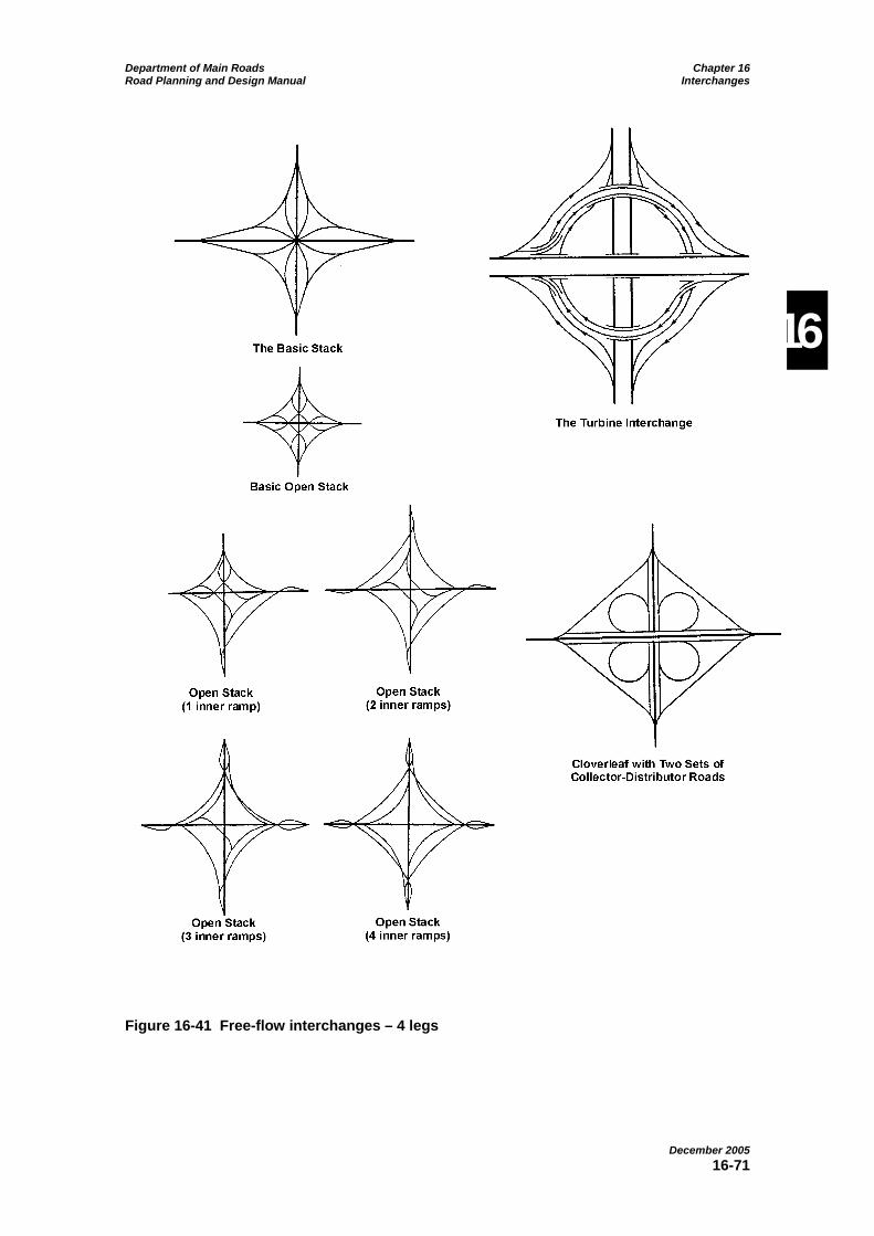
Department of Main Roads Chapter 16 Road Planning and Design Manual Interchanges
December 2005 16-71
16
Figure 16-41 Free-flow interchanges – 4 legs
Department of Main Roads Chapter 16 Road Planning and Design Manual Interchanges
December 2005 16-72
16
Appendix 16C: Example of ramp speed analysis
Example 16C
The upper diagram of Figure 16-42 shows an exit ramp of a partial clover leaf interchange. The diverge speed from the major road is 100km/h and the vehicle path radius on the R30m curve is 32m. A decrease in speed of 56km/h exists at the start of the R30m curve. This decrease in speed combined with the long length of curve (typical for a 270 degree exit ramp) results in a potentially high single vehicle accident rate at this location.
The lower diagram of Example 16C (Figure 16-42) shows the same exit ramp with an additional two reverse curves before the R30m curve. The maximum decrease in speeds between successive elements for this layout is 20km/h as recommended. Fewer single vehicle accidents would be expected on this geometry when compared with the geometry shown in the upper diagram.
The reverse curves shown need to be of minimal length as single vehicle accident rates are proportional to the lengths of the curves. The length of these curves need to be just long enough to achieve the required vehicle path radii. If the ramp consists of multiple lanes, the curves also are required to be long enough to discourage drivers from cutting across lanes.
The driver path radius on the last reverse curve is 150m. This value is significantly greater than the driver path radius on the preceding reverse curve of 70m, and this produces no decrease in vehicle speed on the last curve.
In order to produce a decrease in speed on the last reverse curve, the curve would need
to be reduced to an extremely small radius or would need to be lengthened considerably. The first option would not produce a practical result and the latter would produce unnecessarily long reverse curves that would have a negative impact on safety. Therefore, appropriate design practice in this particular application is to provide no reduction in vehicle speed on the last reverse curve.

Department of Main Roads Chapter 16 Road Planning and Design Manual Interchanges
December 2005 16-73
16
Figure 16-42 Example 16C – exit ramp of a partial clover leaf interchange