Chapter 1520 Roadway Bicycle Facilities 1520 Roadway Bicycle Facilities WSDOT Design Manual M...
32
WSDOT Design Manual M 22-01.12 Page 1520-1 November 2015 Chapter 1520 Roadway Bicycle Facilities 1520.01 General 1520.02 Roadway Bicycle Facility Types 1520.03 Bicycle Facility Selection 1520.04 Intersection Design Treatments 1520.05 Additional Bicycle Design Requirements and Considerations 1520.06 Documentation 1520.07 References 1520.01 General The Washington State Department of Transportation (WSDOT) encourages and relies on bicycle use on and interconnecting with its facilities. Bicycle facilities or improvements for bicycle transportation are included in WSDOT’s project development and highway programming processes. This chapter is a guide for designing bicycle facilities within state highway right of way or between the curb lines on city streets designated as state highways. When designing facilities outside of state highway right of way or beyond the curb on city streets designated as state highways, use the local agency’s design guidance. If the bicycle facility will have shared use with pedestrians incorporate ADA requirements in Chapter 1515. Guidance in this chapter applies to typical situations encountered on state highways, and includes options for intersection and interchange design. Unique design challenges are resolved using expertise and guidance from the regional Bicycle Coordinator or if none exists, the WSDOT headquarters Bicycle Coordinator. Additional concepts to resolve unique bicycle facility design situations can be found in guides referenced (1520.07), but may require additional approvals for signing, pavement markings or bike facility types not presented within this chapter. The region Traffic Engineer is responsible for determining which sections are inappropriate for bicycle traffic on state highways. The State Traffic Engineer, after consultation with the Bicycle Advisory Committee, prohibits bicycling on sections of state highways through the traffic regulation process. Contact the region Traffic Office for further information. 1520.02 Roadway Bicycle Facility Types WSDOT has adopted the following six types of bicycle facilities, from most protected to least protected: • Shared-Use Paths (see Chapter 1515 for guidance) • Raised and Curb-Separated • Separated Buffered Bike Lanes • Buffered Bike Lanes • Conventional Bike Lanes • Shared Lane Markings
-
Upload
truongthuy -
Category
Documents
-
view
242 -
download
0
Transcript of Chapter 1520 Roadway Bicycle Facilities 1520 Roadway Bicycle Facilities WSDOT Design Manual M...

WSDOT Design Manual M 22-01.12 Page 1520-1 November 2015
Chapter 1520 Roadway Bicycle Facilities 1520.01 General 1520.02 Roadway Bicycle Facility Types 1520.03 Bicycle Facility Selection 1520.04 Intersection Design Treatments 1520.05 Additional Bicycle Design Requirements and Considerations 1520.06 Documentation 1520.07 References
1520.01 General
The Washington State Department of Transportation (WSDOT) encourages and relies on bicycle use on and interconnecting with its facilities. Bicycle facilities or improvements for bicycle transportation are included in WSDOT’s project development and highway programming processes.
This chapter is a guide for designing bicycle facilities within state highway right of way or between the curb lines on city streets designated as state highways. When designing facilities outside of state highway right of way or beyond the curb on city streets designated as state highways, use the local agency’s design guidance. If the bicycle facility will have shared use with pedestrians incorporate ADA requirements in Chapter 1515.
Guidance in this chapter applies to typical situations encountered on state highways, and includes options for intersection and interchange design. Unique design challenges are resolved using expertise and guidance from the regional Bicycle Coordinator or if none exists, the WSDOT headquarters Bicycle Coordinator. Additional concepts to resolve unique bicycle facility design situations can be found in guides referenced (1520.07), but may require additional approvals for signing, pavement markings or bike facility types not presented within this chapter.
The region Traffic Engineer is responsible for determining which sections are inappropriate for bicycle traffic on state highways. The State Traffic Engineer, after consultation with the Bicycle Advisory Committee, prohibits bicycling on sections of state highways through the traffic regulation process. Contact the region Traffic Office for further information.
1520.02 Roadway Bicycle Facility Types
WSDOT has adopted the following six types of bicycle facilities, from most protected to least protected:
• Shared-Use Paths (see Chapter 1515 for guidance)
• Raised and Curb-Separated
• Separated Buffered Bike Lanes
• Buffered Bike Lanes
• Conventional Bike Lanes
• Shared Lane Markings
Roadway Bicycle Facilities Chapter 1520
Page 1520-2 WSDOT Design Manual M 22-01.12 November 2015
Shared-use paths (see Chapter 1515) are the most protected type of bike facility because the path is physically separated from motor vehicle traffic most commonly by a wide vegetated outer separation or other physical barrier. Roadway bicycle facilities can range from separated from motor vehicle traffic to physically sharing a lane with motor vehicle traffic. The following subsections discuss five types of roadway bicycle facilities adopted for use on state highways.
All roadway bicycle facility types will be designated by striping, signage, and pavement markings to indicate the preferential or exclusive use for bicycle users. See 1520.05(1) for more information.
1520.02(1) Raised and Curb-Separated
Exhibit 1520-1 shows a raised and curb-separated bicycle facility. These facilities are considered protected because they are vertically separated from motor vehicle traffic. When a raised and curb-separated bicycle facility is applied, it is considered part of the streetside zone (see Chapter 1230); however, it cannot be combined with other zone areas because the intent is also segregation from pedestrians. The raised and curb-separated facility is dedicated for bike users and delineated with pavement markings, signing, and in some cases pavement material.
There are advantages in utilizing streetside zones in conjunction with a raised and curb-separated bike facility. A furnishing zone can be used to help segregate pedestrian and bicycle users or for additional separation between the bike facility and motor vehicle traffic. If a furnishing zone is not used to separate the raised bike facility from the pedestrian zone, consider different pavement types, signs, pavement borders, or striping within the streetside zone to effectively separate pedestrian and bicycle users.
When the raised and curb-separated bike facility is placed adjacent to motor vehicle traffic, consider using a sloped and mountable curb (see Chapter 1230) to enable passing maneuvers between cyclists.
Within incorporated limits, raised and curb-separated bike facilities are located behind the curb and therefore fall under a local agency’s jurisdiction. (See Chapters 1230, and 1600 for additional information on jurisdictional boundaries). In these situations, follow the local agency’s design guidance for this type of bike facility.

Chapter 1520 Roadway Bicycle Facilities
WSDOT Design Manual M 22-01.12 Page 1520-3 November 2015
Exhibit 1520-1 Raised and Curb-Separated Bike Facility
1520.02(2) Separated Buffered Bike Lanes
Separated buffered bike lanes are at grade with the roadway, and they include a bike lane, a buffer area, and some type of vertical feature that reduces the likelihood of encroachment into the bike lane by motor vehicles and increases user comfort. Bike markings (see the Standard Plans) in the bike lane and signage are employed. The most common type of vertical separator used within the buffer area is a pavement mounted flexible tubular marker or delineator. Use of dual-faced curbing, raised medians, or the parking zone adjoining the buffer area can also accomplish the same task.
If parked vehicles within the parking zone are used as the vertical separator, the parking zone cannot encroach onto the buffer area. When a separated buffered bike lane is positioned between motor vehicle lanes and a parking zone, consider including an additional buffer area between the parking zone and bike lane. Use of the buffer area described in these two configurations facilitates loading and unloading of the parked vehicles, and reduces the risk of a

Roadway Bicycle Facilities Chapter 1520
Page 1520-4 WSDOT Design Manual M 22-01.12 November 2015
cyclist being struck when a parked vehicle door opens (aka “dooring”). See NACTO’s Urban Bikeway Design Guide and Urban Street Design Guide for examples.
Exhibit 1520-2 shows an example of separated buffered bike lane using a flexible tubular marker as the vertical separator. A painted buffer strip with flexible tubular marker helps accentuate the bicycle facility from the motor vehicle lane, when curbing or a raised median (also considered vertical separation) is not used for the buffer strip. Consider a 3-foot-wide buffer strip whenever possible. When utilizing a buffer, the bike lane itself may be 3 feet in width. However, 5 feet is recommended exclusively to the bike lane to enable passing maneuvers between cyclists, and account for the effective width needs of bicyclists when drainage features are present in the bike lane. In space constrained areas where inexperienced bicyclists, such as children, are expected or where there is a steep uphill grade use a 4 foot minimum for the bicycle lane. High bicyclist volume locations should consider more width to facilitate mobility performance for this mode. In constrained spaces where lower volumes of cyclists are anticipated and inexperienced bicyclists are not expected, the minimum total width of both the bike lane and buffer combined is 5 feet.
Exhibit 1520-2 Separated Buffered Bike Lane
Chapter 1520 Roadway Bicycle Facilities
WSDOT Design Manual M 22-01.12 Page 1520-5 November 2015
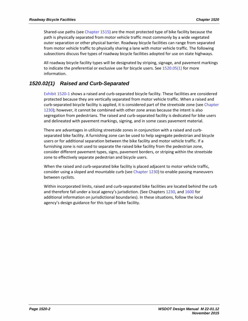
1520.02(3) Buffered Bike Lane
Exhibit 1520-3 shows a buffered bike lane. The design is effectively the same as a separated buffered bike lane (see 1520.02(2)) without the use of vertical separators. Consider a 3-foot buffer strip whenever possible. When utilizing a buffer, the bike lane itself may be 3 feet in width, but it is recommended that 5 feet be provided exclusively to the bike lane to enable passing maneuvers between cyclists. High cyclist volume locations should consider more width to facilitate mobility performance for this mode. In locations where the posted speed is 30mph or less and lower volumes of cyclists are anticipated, the minimum total width of both the bike lane and buffer combined is 5 feet. In locations where inexperienced bicyclists, such as children, are expected or when there is a steep uphill grade the minimum total width of both the bike lane and the buffer combined is 6 feet.
Exhibit 1520-3 Buffered Bike Lane

Roadway Bicycle Facilities Chapter 1520
Page 1520-6 WSDOT Design Manual M 22-01.12 November 2015
1520.02(4) Conventional Bike Lane
Conventional bike lanes are at grade and adjacent to motor vehicle traffic lane and are designated by a single solid wide stripe between the motor vehicle lane and bike lane. Additional bike markings (see the Standard Plans) in the bike lane and signage are employed. A width of 6 feet is recommended for a conventional bike lane when designing for the “Interested, but Concerned” user type. The minimum width for a conventional bike lane is 5 feet when adjacent to curb, or 4 feet when no curb is present. Additional width is considered when higher volumes of cyclists are anticipated or when adjacent to parallel on-street parking. Exhibit 1520-4 shows a conventional bike lane.
Exhibit 1520-4 Bike Lane

Chapter 1520 Roadway Bicycle Facilities
WSDOT Design Manual M 22-01.12 Page 1520-7 November 2015
1520.02(5) Shared Lane
A shared lane is a combined motor vehicle and bicycle lane, as shown in Exhibit 1520-5. Shared lanes are appropriate for lower-speed and lower-volume streets. Shared lanes employ pavement markings and signage to indicate the combined use. Shared lanes are more common in bicycle boulevards, establishing a complete network for cyclists within an urban or suburban environment. Shared lanes may be used on state highways within the ranges presented in 1520.03; however, it is more likely that shared lanes will interface with state highways through crossing situations. It is important to consider how to configure an intersection or dedicated bicycle crossing location when intersecting with a bicycle boulevard network (see 1520.04(5)).
Exhibit 1520-5 Shared Lane Markings

Roadway Bicycle Facilities Chapter 1520
Page 1520-8 WSDOT Design Manual M 22-01.12 November 2015
Shared lane markings (aka “sharrows”) are pavement markings specifically used to indicate a shared lane or intersection space. The position of the marking can encourage a desired lateral position within the lane for cyclists, as well as alerting motor vehicle users. Consider the shared lane marking placement with respect to on-street parking and the potential for dooring that will lower safety performance for the cyclist. Shared lane markings must be placed at least 4 feet from the face of curb, or in the center of the shared lane (or at least 11 feet from face of curb) when an adjacent parallel parking zone is present.
Conventionally, wide lanes have been encouraged for shared-lane applications, to allow for motor vehicles to pass cyclists, or for cyclists to pass motor vehicles in a queue. However, wider lanes may also encourage motor vehicle drivers to travel at higher speeds and a detriment for a shared lane application. Permitting in-lane passing between motor vehicles and bicyclists can lower safety performance for cyclists.
The speed of cyclists can vary significantly between users, and depends on the experience, fitness level of the user, bike technology, and roadway grade. If a shared lane is proposed on an hill, consider a conventional bike lane in the upgrade direction of travel.
1520.02(5)(a) Accommodating Bikes on Shoulders
Many rural highways are used by bicyclists for commuting between cities or for recreation. Providing and maintaining paved shoulders can significantly improve convenience and safety for both bicyclists and motorists along such routes.
Accommodating bicycle users on the shoulder is common on state highways, particularly on rural high-speed facilities. Shoulder improvements to facilitate bicycle travel include widening the shoulders to a minimum of 4 feet, improving roadside maintenance (including periodic sweeping), and removing surface obstacles such as drain grates that are not compatible with bicycle tires. If shoulder rumble strips are present, provide for at least 4 feet of usable shoulder between the rumble strip and the outside edge of shoulder. If guardrail or barrier is present, increase the dimension to 5 feet of usable shoulder.
Accommodating bicycle use on shoulders is appropriate at many locations. Note, however, that bike on shoulder accommodations are not dedicated bicycle facilities, and bicycle users do not have the same operating privileges as with designated roadway bike facilities. In rural to suburban/urban transition areas consider converting the shoulder to a protected buffered bike lane, both to encourage speed management of motor vehicle users through the transition and to establish a dedicated special-use lane for cyclists to tie into the local network.
1520.03 Bicycle Facility Selection
Bicycle facilities are desirable in order to provide viable travel alternatives, and for bicycle users to have the ability to access land use destinations along state highways.
Understand how the state highway interfaces with routes identified as local, state, or regional bike routes. If the state highway is the bike route, intersects with an existing route, or if bicycle users are an identified modal priority (See Chapter 1103), account for the bike facility needs within the design. Other projects need to consider a design that does not preclude the future vision for a planned bike route, depending on the context identification selection (See Chapter 1102) and design year selection (See Chapter 1103).

Chapter 1520 Roadway Bicycle Facilities
WSDOT Design Manual M 22-01.12 Page 1520-9 November 2015
The only instance during planning or design when performance effects on existing or planned bike facilities may not be considered is in locations being designed for the existing context, and the location is prohibits bicycle use. State highways that prohibit bike use can be found here: http://www.wsdot.wa.gov/bike/closed.htm
1520.03(1) Types of Cyclists
Recent research indicates that people have different viewpoints and thresholds that dictate their willingness to utilize bike facilities. Three general types of cyclist users exist:
• Strong and Fearless – This cyclist type are confident not only in their abilities as a cyclist but also with their ability to operate intermixed with other modal users.
• Enthused and Confident – These cyclists prefer utilizing separated facilities, but are comfortable riding intermixed within other modes in some transportation contexts.
• Interested, but Concerned – Cyclists who primarily have safety concerns and who are less skilled or less familiar with the rules of the road, but would like to ride more. These cyclists are frequently dissuaded from cycling, even if bike facilities are present, because of the degree of separation between themselves and other traffic. This category includes children and others new to bicycling.
1520.03(1)(a) Designing for the Interested, but Concerned
The Interested, but Concerned cyclist constitutes the largest segment of cyclist types within suburban, urban and small town populations. Bike facility selection on state routes is based on designing for the “Interested, but Concerned” user type as a starting point. Exhibit 1520-6a shows ranges of applications for the different types of bicycle facilities related to generally accepted safety and mobility performance for this design user.
Other performance needs may increase or decrease the viability of certain types of bike facilities, such as shared-use paths through aesthetic areas or those planned for a mixture of commute and recreational purposes. Further considerations for cyclist perception of comfort are another factor that can affect use of the facility. Designing for a higher level of separation may be more important at locations that serve community activity centers, schools or popular destinations (such as a retail oriented segment of a route) where additional accommodations are appropriate for either the functional uses or less skilled cyclists (including children). In these situations, separated facilities or wider dimensions may provide the level of comfort needed to satisfy user needs and context considerations. Additionally, some suburban, urban, and small town contexts will have more specific bicycle performance needs that will help identify either spot improvements or alteration of the type of existing facility to enhance a specific performance area. Bike facility selection in 1520.03(1)(b) are provided for these reasons.
1520.03(1)(b) Designing for the Confident
In some contexts, it is appropriate to design for the Strong and Fearless, and Enthused and Confident user types. In cases, where right of way is very constrained or where bicycles are not considered the modal priority (see Chapter 1103), it is appropriate to use Exhibit 1520-6b for determining facility selection after input from community engagement efforts. However, understand that the application of Exhibit 1520-6b may result in less mode shift or use of the capacity provided.

Roadway Bicycle Facilities Chapter 1520
WSDOT Design Manual M 22-01.12 Page 1520-10 November 2015
Exhibit 1520-6a Bicycle Facility Selection Chart – Interested, but Concerned Cyclists
Note: Adapted from Montgomery County Bicycle Planning Guidance, Montgomery County Department of Transportation, 2014.

Chapter 1520 Roadway Bicycle Facilities
WSDOT Design Manual M 22-01.12 Page 1520-11 November 2015
Exhibit 1520-6b Bicycle Facility Selection Chart – Confident Cyclists
Roadway Bicycle Facilities Chapter 1520
WSDOT Design Manual M 22-01.12 Page 1520-12 November 2015
1520.03(2) Speed Considerations
While Exhibits 1560-6a and 1560-6b provide ranges of speeds in which different types of bike facilities may be appropriate, it is critical to understand that motor vehicle speed plays a significant role in crash severity between motor vehicles and cyclists. When designing multimodal facilities, a target speed selection within the low speed design control is encouraged. Safety performance increases as motor vehicle speeds are decreased. The optimum target speed for safety performance of multimodal designs is the lowest statutory speed allowed on state routes, which is 25 mph. See Chapter 1103 for further discussion on target speed and speed management treatments.
1520.04 Intersection Design Treatments
The principle objective when designing intersections for bicycle mobility and safety performance is to provide a visible, distinct, predictable, and clearly designated path leading to and through the intersection while managing potential conflicts between all other users and cyclists. This chapter covers options for intersection design for bicyclists while chapters in the 1300 series provide guidance for intersection control type selection and design.
Intersection design to meet the bicycle safety and mobility performance of the cyclist is unique to each location. The primary emphasis is to create a visible, distinct, predictable and clear path for the cyclist to reduce conflicts between cyclists and other design users. This is most commonly achieved through clear delineation of the bike facility leading up to and through the intersection, along with segregating or prioritizing movements between design users. Several proven state-of-the-practice intersection treatments are presented within this section. However, pavement marking or aspects about the configuration may not currently be supported by the Manual on Uniform Traffic Control Devices.
At the time of publication, bike boxes (1520.04(2)) and two-stage left turn lanes (1520.04(3)) are subject to an experimentation request to FHWA. Obtain Headquarters (HQ) Traffic Office approval and assistance with submitting a request for experimentation. Consult, as appropriate, the Federal Highway Administration’s (FHWA) MUTCD website for bicycle facilities for a listing of the current status of bicycle-related pavement markings and treatments: http://www.fhwa.dot.gov/environment/bicycle_pedestrian/guidance/mutcd/index.cfm. See 1520.05(1) for additional information on bicycle pavement markings under MUTCD evaluation.
Note: Exhibits 1520-7 through 1520-9 all show colored pavement markings to increase the safety performance of intersection designs. However, colored pavement markings are not required, and may be added at a later stage if the desired safety performance is not met.
1520.04(1) Approach Through Lanes
The approach to intersections needs to balance the bicycle user’s safety needs with the mobility needs of other users. Clear delineation of user lanes and potential conflict areas is currently the treatment most commonly used to manage the approach to intersections. Use dotted lines to identify the conflict area. Colored pavement markings can be used to further enhance and delineate the conflict area. Exhibit 1520-7 shows different applications of the approach through lane most likely to be encountered.

Chapter 1520 Roadway Bicycle Facilities
WSDOT Design Manual M 22-01.12 Page 1520-13 November 2015
1520.04(2) Bike Boxes and Crossing Pavement Markings
Bike boxes are designated areas for bicyclists positioned across and in front of the bike and motor vehicle lanes as shown in Exhibit 1520-8. Bike boxes are used at signalized intersections and increase both mobility and safety performance for the bicycle mode. Applying a bike box assists mobility performance by prioritizing the bicycle movement at an intersection, and enables a cyclist to position for a left-turn movement. Bike boxes have also been found to prevent cyclist and motor vehicle encroachment into the pedestrian crossing, reducing conflicts with pedestrians at intersections. Bicycle safety performance is improved by increasing the visibility of the cyclist, and by reducing conflicts between motor vehicles making a right turn and the bicycle through movement (also known as “right-hook” conflict).
There are several different ways to delineate bike lanes through the intersection. Dotted lines are the most common, but can be combined with sharrows or green pavement markings (see 1520.05(1)) to further enhance the bike facility’s presence and position within an intersection.
1520.04(3) Two-Stage Left Turns
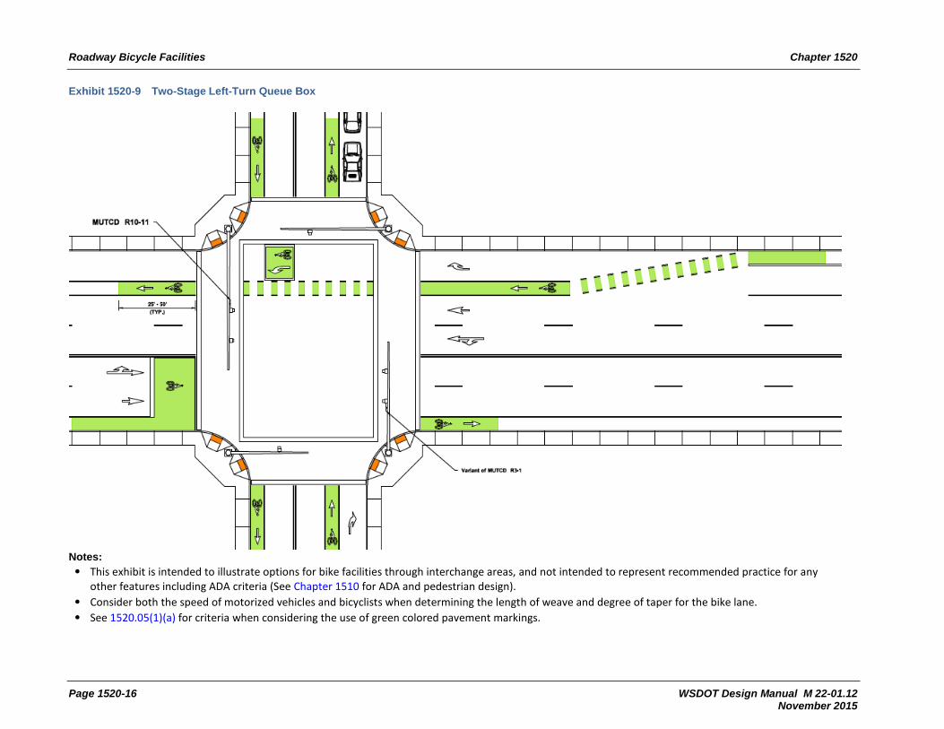
Exhibit 1520-9 shows an example of a two-stage left-turn design for bicycle users. This design utilizes a rectangular bike box to enable cyclist queueing at the crossroad signal phase. The bicyclist passes partway through the intersection to access the bike box, and then waits for the crossroad next signal phase to eliminate the bicyclist left turn movement. This treatment is has best value at intersections with significant volumes of motor vehicle traffic or large volumes of left-turn cyclists, or when separated or buffered roadway bicycle facilities are used on the segment.
This treatment can increase safety performance by reducing conflicts between cyclists and other users, segregating motor vehicle and bicycle users, and separating turning cyclists from through cyclists.
The position of the queue box is a critical aspect of this intersection design. Depending on the size and configuration of the intersection, it may present a modal performance trade-off between bicycle mobility and safety versus motor vehicle mobility performance. Use turn simulation software to verify the queue box is outside the crossroad left-turn path, or restrict left turns at the crossroad to accommodate the queue box. Similarly, right turns may need to be restricted for motor-vehicles approaching the queue box if motor vehicle right-turn lanes or right-turn pockets are not present.

Roadway Bicycle Facilities Chapter 1520
Page 1520-14 WSDOT Design Manual M 22-01.12 November 2015
Exhibit 1520-7 Approach Through Lanes
Notes:
• Not to scale and not all dimensions shown. • See 1520.05(1)(a) for criteria when considering the use of green colored pavement markings. • Consider both the speed of motorized vehicles and bicyclists when determining the length of weave and degree of taper for the bike lane.

Chapter 1520 Roadway Bicycle Facilities
WSDOT Design Manual M 22-01.12 Page 1520-15 November 2015
Exhibit 1520-8 Bike Box and Intersection Crossing Markings
Notes: • This exhibit is intended to illustrate options for bike facilities through interchange areas, and not intended to represent recommended practice for any
other features including ADA criteria (See Chapter 1510 for ADA and pedestrian design). • See 1520.05(1)(a) for criteria when considering the use of green colored pavement markings.
Roadway Bicycle Facilities Chapter 1520
Page 1520-16 WSDOT Design Manual M 22-01.12 November 2015
Exhibit 1520-9 Two-Stage Left-Turn Queue Box
Notes: • This exhibit is intended to illustrate options for bike facilities through interchange areas, and not intended to represent recommended practice for any
other features including ADA criteria (See Chapter 1510 for ADA and pedestrian design). • Consider both the speed of motorized vehicles and bicyclists when determining the length of weave and degree of taper for the bike lane. • See 1520.05(1)(a) for criteria when considering the use of green colored pavement markings.

Chapter 1520 Roadway Bicycle Facilities
WSDOT Design Manual M 22-01.12 Page 1520-17 November 2015
Exhibit 1520-10 Median Refuge Island for Cyclists

Roadway Bicycle Facilities Chapter 1520
Page 1520-18 WSDOT Design Manual M 22-01.12 November 2015
1520.04(4) Traffic Signals Considerations
Consider bicycle needs and intersection geometry when timing the traffic signal cycle and when selecting the method of detecting the presence of cyclists. Contact the regional Bicycle Coordinator and region Traffic Engineer for assistance in determining the timing criteria. At a minimum consider safety performance needs, projected bicycle volume, motor vehicle volume, traffic delay, roadway grade and the types of bicyclists using the intersection that may require more time to clear the intersection. Consider the installation of effective loop detectors or other methods of detecting a bicycle within the bike lane (in advance of the intersection) and turn lanes. Select detectors sensitive enough to detect bicycles, and use a bike detector symbol to identify detector presence.
Push button actuators may also be used to facilitate movement of bicyclists through a signalized intersection. However, requiring bicyclists to go out of their way to use push button actuators may create motor vehicle driver confusion of the bicyclists intended path through the intersection, as well as inconveniencing the bicyclist. If pushbutton actuators are used, consider their position relative to the bike facility. Pushbutton actuators are more effective when the bike facility is adjacent to the curb (curb extensions at intersections can create this environment). Consider an additional push button actuator for the exclusive use of cyclists when positioning of the actuator is in conflict with ADA design requirements (see Chapter 1510). For additional guidance on signal design, see Chapter 1330.
1520.04(4)(a) Bike Signals
Intersections with separated bike lanes, other complex multimodal intersection treatments or those with a specific baseline need to increase bicycle user safety performance may incorporate a dedicated bike signal head with detection or actuation systems. Bike signal heads further separate modal user movements at intersections, while also allowing for priority to cyclists at intersections. Contact the region Traffic Engineer for approval for application of this treatment.
At the time of this publication, bike signal faces are subject to requirements of FHWA Interim Approval for this treatment. For current status of the treatment and conditions of the Interim Approval, if still applicable, see http://www.fhwa.dot.gov/environment/bicycle_pedestrian/guidance/mutcd/index.cfm
1520.04(5) Median Refuge Islands for Cyclists
Layered networks have the benefit of separating modes onto different facilities to either enhance mobility or safety performance of active transportation modes. However, layered networks do intersect and specific median treatments exist to manage the confluence of these networks.
Median refuge islands provide a refuge for bicyclists to cross one direction of traffic at a time while restricting motor-vehicle through movements on crossroads designated as primary bicycle corridors or bike boulevards. The treatment minimizes impacts for bicyclists on the crossroad while prohibiting motor vehicle left turn movements from the cross street to eliminate conflicts.

Chapter 1520 Roadway Bicycle Facilities
WSDOT Design Manual M 22-01.12 November 2015
Consider median refuge islands when one or more of the following occurs:
• Bike facilities cross a roadway with median restricted left turns.
• Bike facilities cross a moderate to high (motor vehicle) volume roadway, with intermediate motor-vehicle speeds
• Bike facilities cross a 4 lane divided highway.
• Separated or buffered bike facilities used on the cross street.
• There is a performance need to restrict motor vehicle through traffic on a bike route.
• Safety or mobility performance need of mainline cyclists exist for left turning movements onto a bike route or shared use pathway
Exhibit 1520-10 shows an example of a median refuge designed for cyclists. Design refuge areas between 4 and 5 feet wide (longitudinally with respect to the median), additional width may be needed if high volumes of cyclists exist or are anticipated at the crossing. Consider the types of cyclists and destinations when determining the median refuge length (lateral dimension with respect to the median) to adequately store the bicycle. Consider what locations may need to accommodate the length of a bicycle and trailer. The refuge area is to be in alignment with the approach and receiving lanes of the crossroad. In other situations the median refuge island may be designed for both pedestrians and bicycle users. When this is the case, design the median refuge predominately for the pedestrian as with midblock crossings (See Chapter 1510), note that additional lateral and longitudinal dimensions will be necessary.
1520.05 Additional Bicycle Design Requirements and Considerations
1520.05(1) Signing and Pavement Markings
Use the MUTCD and the Standard Plans for signing and pavement marking criteria. (See Chapter 1020 for additional information on signing and Chapter 1030 for information on pavement markings). Pavement marking and signing options for bicycle facilities are rapidly changing. Situations may exist where unique project concerns may necessitate innovative pavement markings or signage. Consult, as appropriate, the Federal Highway Administration (FHWA) MUTCD website for bicycle facilities for a listing of the current status of bicycle-related pavement markings and treatments: http://www.fhwa.dot.gov/environment/bicycle_pedestrian/guidance/mutcd/index.cfm
HQ Traffic Office approval is necessary for traffic control devices not currently approved for use through the MUTCD.
1520.05(1)(a) Green Pavement Marking – Criteria for Consideration
Green -colored pavement markings are a traffic control device whose need must be demonstrated before use and documented with a design decision. The highest benefit of applying green colored pavement markings occurs where the potential conflicts exist between cyclists and other design users, or when other design users should yield to cyclists. Green colored pavement markings are only intended as a supplemental treatment for standard striping configurations for bicycle facilities.

Roadway Bicycle Facilities Chapter 1520
Page 1520-20 WSDOT Design Manual M 22-01.12 November 2015
The below criteria are provided when evaluating the need to apply green colored pavement markings.
1. Existing Bike Facilities – retrofitting an existing facility with green pavement may be considered when two or more of the following apply:
a. It is the engineering judgment of the Region Traffic Engineer
b. There is an existing traffic conflict area, such as bike lane crossing a motor vehicle turn lane, and there are one or more observed motor vehicle and bicyclist crashes in the last 5 years.
c. The bike mode is a modal priority (see Chapter 1103), and there is a baseline or contextual need identified associated with increasing safety performance of the mode.
d. When a bike route intersects a multilane highway, and the crossing is neither signalized nor a roundabout.
2. Changing of Bike Facility Type –consider green pavement markings when one or more of the following apply:
a. It is the engineering judgment of the Region Traffic Engineer.
b. A transition from a separated facility through a functional intersection or interchange area necessitates additional delineation to create a clear, visible, predictable and distinct travel path for bike users, and a bike signal or actuation device is not used.
c. The facility type change does not substantively alter the configuration of an existing conflict area, and there are one or more observed motor vehicle and bicyclist crashes in the last 5 years at that conflict area.
3. New Bike Facility – Generally, the immediate application of green colored pavement on a new bike facility is discouraged until the need for increased safety performance is demonstrated. This said, consider green colored pavement when two or more of the following conditions exist:
a. It is the engineering judgment of the Region Traffic Engineer
b. The bike mode is a modal priority (see Chapter 1103), and there is a baseline or contextual need in which the application of green colored pavement markings is needed to meet the stated modal safety performance target (see Chapter 1101).
c. The bike facility nodes and/or crossings are within 1 mile of activity centers, such as schools, libraries, colleges, etc.
d. The bike facility crosses a motor vehicle free right turn to or from an interchange ramp.
e. The bike facility is a bike route or bike boulevard (for definition, see NACTO’s Urban Bikeway Design Guide).
f. The state route is also a city street, and the city policy or municipal code requires green colored pavement markings as their standard.
g. The bike facility is raised and curb separated, and the city engineer requests green colored pavement markings at either crossings or conflict areas.

Chapter 1520 Roadway Bicycle Facilities
WSDOT Design Manual M 22-01.12 November 2015
1520.05(1)(b) Green Pavement Marking – Configuration
Use green pavement markings to supplement the conventional white bike lane striping as required by the MUTCD. Apply green colored pavement markings in conflict areas, consistent with what is shown in Exhibits 1520-7 through 1520-9. Preceding the conflict area, apply solid green 25-50 feet in length (see Exhibit 1520-11), use green ladder striping between the required white dotted striping through the extent of the conflict area, and apply solid green after the ladder striping for at least 25 ft but no more than 50 ft. If closely spaced conflict areas exist, it may be appropriate to carry solid green into the next conflict area as determined by the Region Traffic Engineer.
1520-11 Length of Solid Green Pavement Marking Preceding Conflict Area
Motor Vehicle Speed
Length of Solid Green Colored Pavement Marking Preceding Conflict Area
25 mph 25 ft
30 mph 30 ft
35 mph or more 35-50 ft
Interchange Ramps See 1520.05(6)
Additional configurations or styles exist for the application of green colored pavement and can be used with the approval of HQ Traffic Office. Consider specifically when bike route continuity with a local agency’s bike facilities is a concern.
1520.05(2) Drainage Grates and Manhole Covers
Locate drainage inlet grates and manhole covers to avoid bike lanes. When drainage grates or manhole covers are located in a bike lane, minimize the effect on bicyclists. Consider providing 3 feet of lateral clearance between the edge of a drainage inlet grate and the bike lane stripe, when practicable. Install and maintain grates and manhole covers level with the surface of the bike lane.
Provide drainage inlet grates on bicycle facilities that have openings narrow enough and short enough that bicycle tires will not drop into the grates. Replace existing grates that are not designed for bicycles: a WSDOT vanned grate, herringbone grate, or other grate with an opening 4 inches or less center to center and perpendicular to the direction of travel.
1520.05(3) At-Grade Railroad Crossings
Whenever a bike lane crosses railroad tracks, continue the crossing at least as wide as the bike lane. Use special construction and materials to keep the flangeway depth and width to a minimum. Wherever possible, design the crossing at right angles to the rails. Where a skew is unavoidable, widen the shoulder or bike lane, to permit bicyclists to cross at right angles. Exhibit 1520-12 shows options and details to consider for at-grade railroad crossings.

Roadway Bicycle Facilities Chapter 1520
Page 1520-22 WSDOT Design Manual M 22-01.12 November 2015
Exhibit 1520-12 At-Grade Railroad Crossings
Widened Shoulder
Shoulder
Bikeway
Direction ofbicycle travel
Widen to permit right angle crossing
Striped
Large radii desirable
RR Tracks
90o Crossing(most desirable)
Additional R/W required
Curve widening
Bikeway
Shoulder
Additional R/W required
Bikeway
Curvewidening
Railroad R
/W
45°
45o Crossing(acceptable)
Bikeway
Shoulder
14 ftmax
Bikeway
Railroad R
/W
Railroad R
/W
Hig
hway
R/W
Notes:
• Provide additional width at railroad crossings to allow bicyclists to choose their own crossing routes.
• When pedestrians are provided for, design as a shared-use path (see Chapters 1510 and 1515).

Chapter 1520 Roadway Bicycle Facilities
WSDOT Design Manual M 22-01.12 November 2015
1520.05(4) Barrier and Railing
When the edge of the bike lane is within 5 feet of a barrier or railing, provide a barrier height a of 42 inches or more to reduce the potential for bicyclists to fall over the barrier (see Exhibit 1520-13). When the bicycle facility is adjacent to barrier, consider single slope barrier to mitigate for pedal movement conflicts other barrier designs.
On structures, the bridge railing type and height are part of the structure design. Contact the HQ Bridge and Structures Office for additional information. (See Chapter 720 for further considerations.)
Exhibit 1520-13 Barrier Adjacent to Bicycle Facilities
Bike Lane
Bike lane between edge of traveled way and barrier
42" [1][2]
Edge of traveled way
Bike lane
Bike Lane With Sidewalk or Curb
Bike lane between edge of traveled way and sidewalk
Edge of traveled way
Notes:
[1] Height does not apply to bridge railing. On structures, the bridge railing type and height are part of the structure design. (Contact the HQ Bridge and Structures Office for additional information.)
[2] Applies to bike lanes. Additional height is not needed for shared-use roadways.

Roadway Bicycle Facilities Chapter 1520
Page 1520-24 WSDOT Design Manual M 22-01.12 November 2015
1520.05(5) Transit Considerations
Transit and bicycle facilities can generate unique conflicts because of their typical position within the geometric cross section of the traveled way zone. Where public transport and cycling facilities meet, an integrated design that does not inconvenience either mode is desirable to meet the performance needs of these modes. Consider the following:
• Route the bike lane behind the transit stop location using a raised bike lane or outer separation for that spot location. Ensure the resulting outer separation provided for the transit stop meets the Americans with Disabilities Act (ADA) requirements (see Chapter 1510). Ensure signing and pavement markings are used to alert cyclists and pedestrians of the conflict area created with this design.
• Provide additional delineation in the bike lane to highlight the pedestrian and cyclist conflict, when separated buffered bike lanes and in-lane transit stops are used. Bus loading and other conflict areas will need to meet ADA requirements (see Chapter 1510) and those of the transit agency.
• Where bus operating speeds are low, consider a bus-bicycle shared lane with the transit agency.
Consider providing bicycle parking facilities near public transportation stops to improve accessibility performance needs.
1520.05(6) Interchange Considerations
Crossing bicycle facilities through an interchange functional area has a greater potential for conflict because of higher travel speeds and lane configurations. Interchange crossings designed in a manner similar to intersection crossings are more compatible to bicyclists. Exhibits 1520-14a through 1520-14d illustrate design options for bike facilities design through an interchange functional area. Interchanges can be special environments to evaluate the safety and mobility needs of the bike mode. The specific challenge is often the inclusion of motor vehicle free right turns to or from interchange ramps. The preferred configuration for bicycle safety performance at an interchange will not provide the motor vehicle free right turn, and will realign ramps to intersect perpendicular with the crossroad (see off ramp terminal in Exhibit 1520-14a). However, given the modal priorities and operational performance needs of those priorities, this configuration may not always be practicable.
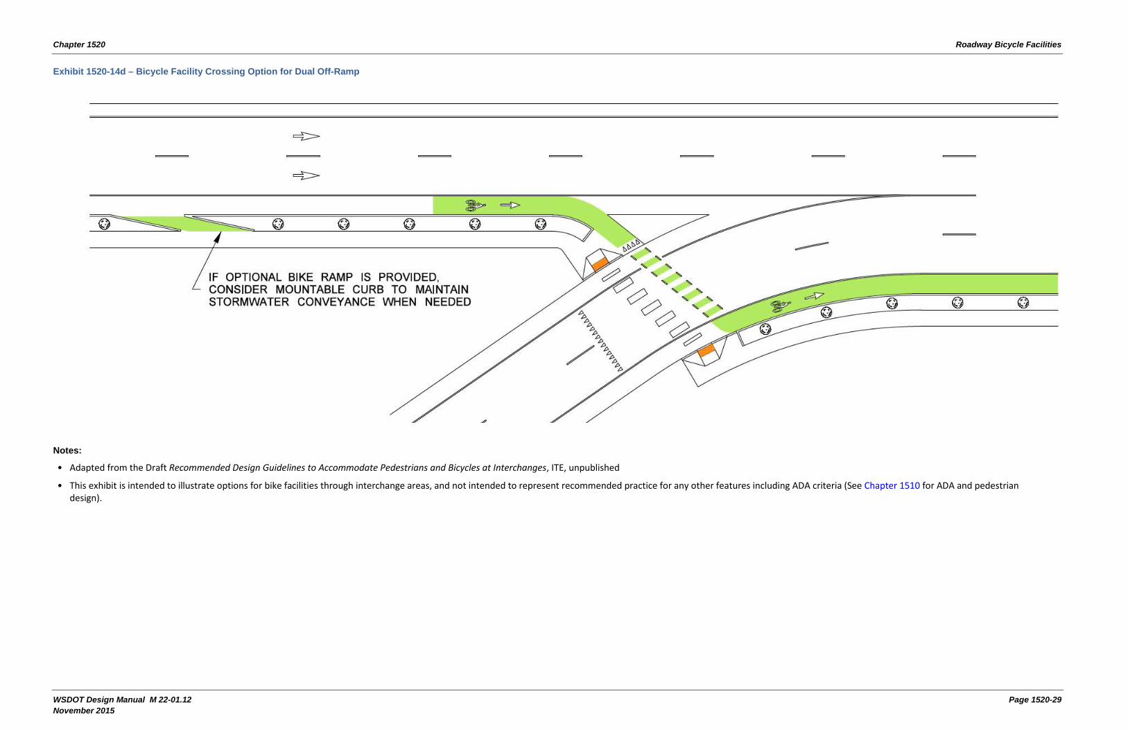
In some cases, it is possible to align the bike facility to cross an off ramp with a more direct path for the bike crossing (see Exhibit 1520-14d). Breaking up the work load for the motor vehicle driver is one advantage of this configuration, similar to pedestrian treatments common in roundabout design. Shortening the crossing distance required for the bicyclist is another advantage with this configuration. Consider the inclusion of Rectangular Rapid Flashing Beacons (RRFB) or a refuge island when there are multiple travel lanes. This configuration may also require additional speed management (see Chapter 1103), signing or striping treatments on the ramp.
Other situations may dictate additional delineation parallel to and matching the length of the auxiliary lane provided at the ramp terminal as shown in Exhibit 1520-14b. This configuration can be coupled with additional signing preceding the motor vehicle merge, and additional separation or a buffer between the ramp’s auxiliary lane and the through bike lane. The length of the motorized auxiliary lane will vary depending on speed and volume, so the length of green

Chapter 1520 Roadway Bicycle Facilities
WSDOT Design Manual M 22-01.12 November 2015
markings shown in Exhibit 1520-11 may not adequately satisfy the delineation desired at these locations. Consult with the Region Traffic Engineer for determining the length of green pavement markings at interchange locations, when they are provided according to 1520.05(1)(a).
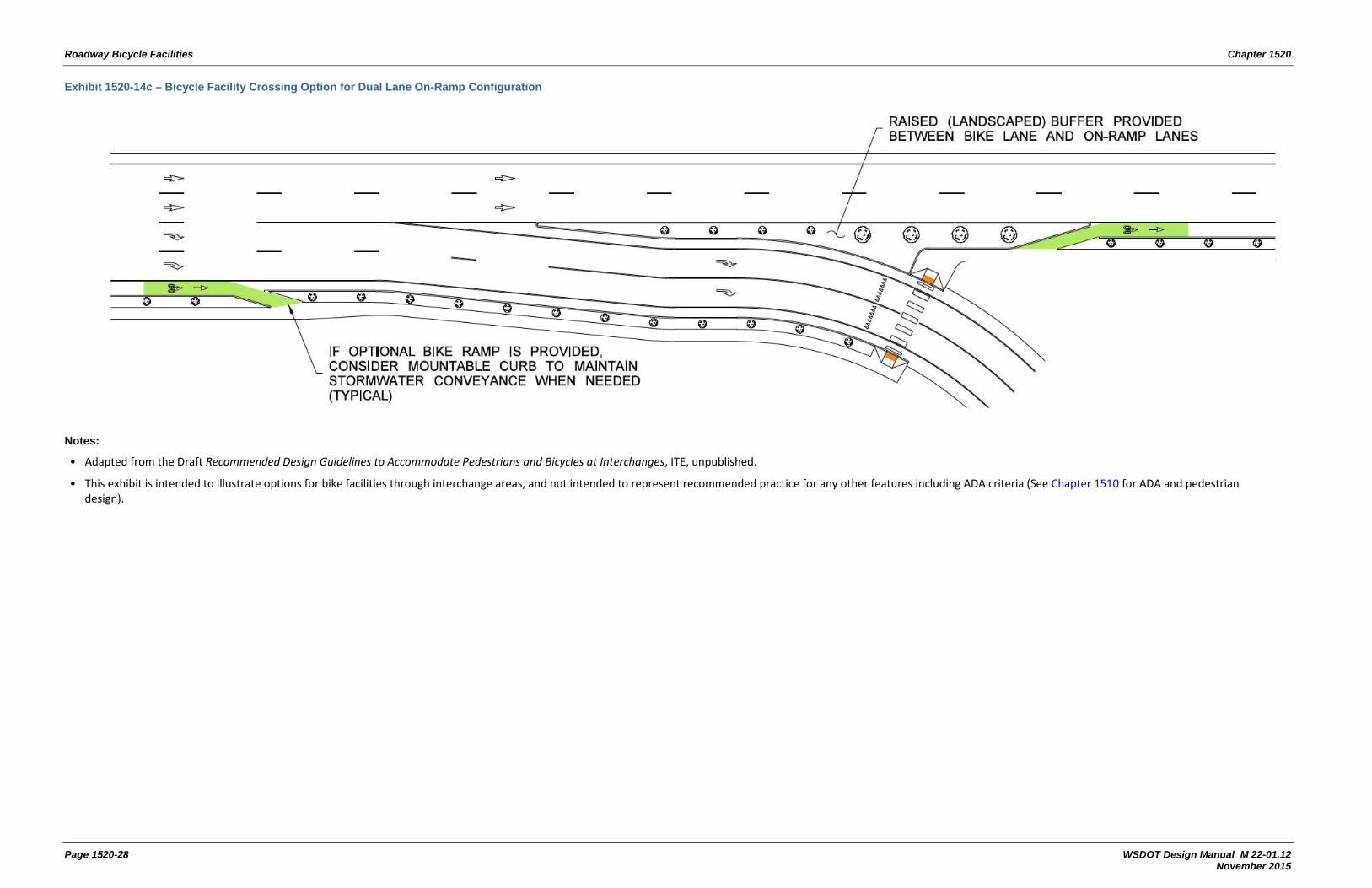
Exhibit 1520-14c provides a design option in which the bike lane merges with the sidewalk, and requires bicyclists to cross an interchange ramp at the pedestrian crossing. This configuration is ideal when bicycle mode is not identified as a modal priority, there is high motor vehicle ADT, there is a large intersection design vehicle, there is intermediate to high motor vehicle speeds, or when there are identification design users (see Chapter 1103) that suggests low experienced bicyclists will be present. Consider inclusion of an RRFB or a median refuge island when there are multiple lanes. Exhibits 1520-14b and 1520-14d also show the option of providing a bike ramp to the sidewalk. Providing options for cyclists at interchanges is encouraged, since the range of comfort among users is known to be diverse. Consult with the local agency regarding any prohibitions against bicyclists using the sidewalk that may negate the ability to implement this configuration.

Roadway Bicycle Facilities Chapter 1520
Page 1520-26 WSDOT Design Manual M 22-01.12 November 2015
Exhibit 1520-14a – Bike Facility Crossing On and Off Ramps
Notes:
• Adapted from the Draft Recommended Design Guidelines to Accommodate Pedestrians and Bicycles at Interchanges, ITE, unpublished.
• This exhibit is intended to illustrate options for bike facilities through interchange areas, and not intended to represent recommended practice for any other features including ADA criteria (See Chapter 1510 for ADA and pedestrian design).

Chapter 1520 Roadway Bicycle Facilities
WSDOT Design Manual M 22-01.12 Page 1520-27 November 2015
Exhibit 1520-14b – Bicycle Facility Crossing Single Lane On Ramp
Notes:
• Adapted from the Draft Recommended Design Guidelines to Accommodate Pedestrians and Bicycles at Interchanges, ITE, unpublished.
• This exhibit is intended to illustrate options for bike facilities through interchange areas, and not intended to represent recommended practice for any other features including ADA criteria (See Chapter 1510 for ADA and pedestrian design).
• Consider both the speed of motorized vehicles and bicyclists when determining the length of weave and degree of taper for the bike lane.
Roadway Bicycle Facilities Chapter 1520
Page 1520-28 WSDOT Design Manual M 22-01.12 November 2015
Exhibit 1520-14c – Bicycle Facility Crossing Option for Dual Lane On-Ramp Configuration
Notes:
• Adapted from the Draft Recommended Design Guidelines to Accommodate Pedestrians and Bicycles at Interchanges, ITE, unpublished.
• This exhibit is intended to illustrate options for bike facilities through interchange areas, and not intended to represent recommended practice for any other features including ADA criteria (See Chapter 1510 for ADA and pedestrian design).
Chapter 1520 Roadway Bicycle Facilities
WSDOT Design Manual M 22-01.12 Page 1520-29 November 2015
Exhibit 1520-14d – Bicycle Facility Crossing Option for Dual Off-Ramp
Notes:
• Adapted from the Draft Recommended Design Guidelines to Accommodate Pedestrians and Bicycles at Interchanges, ITE, unpublished
• This exhibit is intended to illustrate options for bike facilities through interchange areas, and not intended to represent recommended practice for any other features including ADA criteria (See Chapter 1510 for ADA and pedestrian design).
Roadway Bicycle Facilities Chapter 1520
Page 1520-30 WSDOT Design Manual M 22-01.12 November 2015
1520.05(7) Sight Triangles at Intersections and Conflict Areas
The visibility of all users is to be evaluated at intersections. Identifying sight triangles can help determine the optimal configuration of bicycle and pedestrian crossings. See Chapter 1310 for determining sight distance at an intersection, and Chapter 1340 for sight distance at road approaches near midblock crossings. Visibility is impacted by both speed and the configuration of the intersection. There are multiple benefits in multimodal intersection configurations to proactively manage motorized vehicle speeds (see Chapter 1103 for speed reducing traffic calming treatments) at intersection locations, rather than widening the intersection and/or removing elements from the roadside or streetside zone to obtain the needed sight distance. The primary objective at intersections and interchanges is to create a clear, distinct, and predictable travel path for all users through the intersection.
1520.05(8) Maintenance Considerations
Consult with all maintenance jurisdictions for partnering opportunities and clearly understand which jurisdiction will be responsible for specific elements of the bike facility maintenance. Some maintenance jurisdictions may be better equipped to maintain the bike facility than others. Certain bike facilities, like the raised and curb separated, clearly fall within the jurisdictional authority of an incorporated city (see chapters 1230 and 1600 for more information). For other facility types it may be more advantageous to discuss the capabilities of each maintenance jurisdiction, and develop a maintenance agreement (see Chapter 301).
It is important to obtain information from maintenance regarding the facility type and dimensioning, and discuss methods for maintaining the facility. The Maintenance Owner’s Manual (See Chapter 301) is suggested to contain frequency, equipment needs and material types necessary for the continual maintenance of facility features, including but not limited to:
• Sweeping
• Snow removal
• Striping and pavement markings
• Signing
1520.06 Documentation
Document the type of bike facility employed or changed in section 5 of the Basis of Design. Dimensions chosen for the facility are documented on design parameter sheets.

Chapter 1520 Roadway Bicycle Facilities
WSDOT Design Manual M 22-01.12 Page 1520-31 November 2015
1520.07 References
1520.07(1) Federal/State Laws and Codes
Americans with Disabilities Act of 1990 (ADA)
23 Code of Federal Regulations (CFR) Part 652, Pedestrian and Bicycle Accommodations and Projects
Revised Code of Washington (RCW), Chapter 35.75, Streets – Bicycles – Paths http://apps.leg.wa.gov/rcw/default.aspx?cite=35.75
RCW 46.04, Definitions http://apps.leg.wa.gov/rcw/default.aspx?cite=46.04
RCW 46.61, Rules of the road http://apps.leg.wa.gov/rcw/default.aspx?cite=46.61\
RCW 46.61.710, Mopeds, electric-assisted bicycles – General requirements and operation http://apps.leg.wa.gov/rcw/default.aspx?cite=46.61.710
RCW 47.26.300, Bicycle routes – Legislative declaration http://apps.leg.wa.gov/rcw/default.aspx?cite=47.26.300
1520.07(2) Supporting Information
Urban Bikeway Design Guide, NACTO, current edition (WSDOT endorsed) http://nacto.org/publication/urban-bikeway-design-guide/
Guide for the Development of Bicycle Facilities, AASHTO, current edition https://bookstore.transportation.org/collection_detail.aspx?ID=116
Separated Bike Lane Planning and Design Guide, FHWA, current edition http://www.fhwa.dot.gov/environment/bicycle_pedestrian/publications/separated_bikelane_pdg/page00.cfm
Bicycle Parking Guidelines, Association of Pedestrian and Bicycle Professionals, current edition http://www.apbp.org/?page=Publications
Manual on Uniform Traffic Control Devices for Streets and Highways, USDOT, FHWA; as adopted and modified by Chapter 468-95 WAC “Manual on uniform traffic control devices for streets and highways” (MUTCD) www.wsdot.wa.gov/publications/manuals/mutcd.htm
Standard Plans for Road, Bridge, and Municipal Construction (Standard Plans), M 21-01, WSDOT www.wsdot.wa.gov/publications/manuals/m21-01.htm
Understanding Flexibility in Transportation Design – Washington, WSDOT, 2005 www.wsdot.wa.gov/research/reports/600/638.1.htm
Selecting Roadway Design Treatments to Accommodate Bicycles, USDOT, Federal Highway Administration (FHWA), 1994
Roadway Bicycle Facilities Chapter 1520
Page 1520-32 WSDOT Design Manual M 22-01.12 November 2015
NCHRP Report 766: Recommended Bicycle Lane Widths for Various Roadway Characteristics, Transportation Research Board of the National Academies, 2014 http://onlinepubs.trb.org/onlinepubs/nchrp/nchrp_rpt_766.pdf
NCHRP Report 500 Volume 18: A Guide for Reducing Collisions Involving Bicycles, Transportation Research Board of the National Academies, 2006 http://onlinepubs.trb.org/onlinepubs/nchrp/nchrp_rpt_500v18.pdf
Four Types of Cyclists?, Dill, Jennifer, and Nathan McNeil, Transportation Research Record: Journal of the Transportation Research Board 2387.1 (2013): 129-138.
Recommended Design Guidelines to Accommodate Pedestrians and Bicycles at Interchanges, ITE, unpublished. http://ecommerce.ite.org/IMIS/ItemDetail?iProductCode=RP-039
Montgomery County Bicycle Planning Guidance, Montgomery County Department of Transportation, 2014. http://www.montgomeryplanning.org/transportation/bikeways/documents/FINALBicyclePlanningGuidance.pdf
Separated Bike Lane Planning and Design Guide, Massachusetts Department of Transportation (MassDOT), 2015 http://www.massdot.state.ma.us/highway/DoingBusinessWithUs/ManualsPublicationsForms/SeparatedBikeLanePlanningDesignGuide.aspx
http://www.montgomeryplanning.org/transportation/bikeways/documents/FINALBicyclePlanningGuidance.pdf