CHAPTER 1513 DEPARTMENT OF AGRICULTURE ANHYDROUS …
33
13 CHAPTER 1513 DEPARTMENT OF AGRICULTURE ANHYDROUS AMMONIA 1513 0010 INTRODUCTION 1513 0020 INCORPORATIONS BY REFERENCE 1513 0030 DEFINITIONS 1513 0040 SAFETY BASIC RULES 1513 0100 APPLICABILITY 1513 0110 EXISTING EQUIPMENT AND SYSTEMS 1513 0120 NEW CONSTRUCTION, REPAIRS, ALTERATIONS, AND ORIGINAL TEST OF CONTAINERS, OTHER THAN REFRIGERATED STORAGE TANKS 1513 0130 LOCATION OF CONTAINERS 1513 0140 MARKINGS OF NONREFRIGERATED CONTAINERS AND SYSTEMS OTHER THAN DOT CONTAINERS 1513 0150 CONTAINER APPURTENANCES 1513 0160 PIPING, TUBING, AND FITTINGS 1513 0170 HOSE SPECIFICATIONS 1513 0180 PRESSURE RELIEF DEVICES 1513 0190 FILLING DENSITIES 1513 0200 TRANSFER OF LIQUIDS 1513 0210 LIQUID LEVEL GAUGING DEVICES 1513 0220 PAINTING OF CONTAINERS 1513 0230 ELECTRICAL EQUIPMENT AND WIRING SYSTEMS USING STATIONARY, PIER-MOUNTED, OR SKID-MOUNTED ABOVEGROUND OR UNDERGROUND, NONREFRIGERATED STORAGE 1513 0300 APPLICABILITY 1513 0310 DESIGN PRESSURE AND CONSTRUCTION OF CONTAINERS 1513 0320 CONTAINER VALVES, ACCESSORIES, AND DISCHARGE CONNECTIONS 1513 0330 PRESSURE RELIEF DEVICES 1513 0340 INSTALLATION OF STORAGE CONTAINERS 1513 0350 REINSTALLAITON OF CONTAINERS 1513 0360 MARKING CONTAINERS 1513 0370 PROTECTION OF CONTAINER AND APPURTENANCES 1513 0380 IDENTIFICATION 1513 0400 REFRIGERATED STORAGE 1513 0410 DESIGN OF TANKS 1513 0420 INSTALLATION OF STORAGE TANKS ABOVEGROUND 1513 0430 MARKING REFRIGERATED CONTAINERS 1513 0440 TANK VALVES, ACCESSORIES, FILL PIPES, AND DISCHARGE PIPES 1513 0450 PRESSURE RELIEF VALVES 1513 0460 PROTECTION OF CONTAINERS AND APPURTENANCES 1513 0470 REINSTALLATION OF CONTAINERS 1513 0480 REFRIGERATION LOAD AND EQUIPMENT 1513 0490 SAFETY EQUIPMENT 1513 0500 IDENTIFICATION RAILROAD TANK CARS 1513 0600 APPLICABILITY 1513 0610 DESIGN AND CONSTRUCTION 1513 0620 PRESSURE RELIEF VALVES 1513 0630 MARKING AND PLACARDING 1513 0640 TANK CAR LOADING AND UNLOADING LOCATIONS AND OPERATIONS SYSTEMS MOUNTED ON TRUCKS, SEMI-TRAILERS, AND TRAILERS FOR TRANSPORTATION OF AMMONIA 1513 0700 APPLICABILITY 1513 0710 DESIGN PRESSURE OF CONTAINERS 1513 0720 CONTAINER MOUNTING 1513 0730 CONTAINER APPURTENANCES 1513 0740 PIPING, TUBING, FITTINGS, AND HOSE 1513 0750 PRESSURE RELIEF VALVES 1513 0760 PLACARDING AND MARKING OF CONTAINER 1513 0770 TRANSFER OF LIQUIDS 1513 0780 TRAILERS AND SEMI-TRAILERS 1513 0790 ELECTRICAL EQUIPMENT AND LIGHTING 1513 0800 PROTECTION -AGAINST COLLISION 1513 0810 BRAKES 1513 0820 PORTABLE TANKS 1513 0830 SAFETY EQUIPMENT SYSTEMS USING DOT PORTABLE TANKS AND CYLINDERS 1513 0900 APPLICABILITY 1513 0910 CONTAINERS AND CYLINDERS 1513 0920 CONTAINER AND CYLINDER VALVES AND REGULATION EQUIPMENT 1513 0930 PRESSURE RELIEF DEVICES SYSTEMS FOR TRANSPORTATION OF AMMONIA MOUNTED ON FARM WAGONS AND EQUIPMENT OR IMPLEMENTS OF HUSBANDRY 1513 1000 APPLICABILITY 1513 1010 DESIGN OF CONTAINERS 1513 1020 MOUNTING OF CONTAINERS 1513 1030 CONTAINER APPURTENANCES 1513 1040 PLACARDING AND MARKING OF CONTAINERS 1513 1050 FARM WAGONS AND EQUIPMENT 1513 1060 SAFETY EQUIPMENT '1513 1070 CHEMICAL ADDITIVE COMPATIBILITY MINIMUM REQUIRED FLOW RATE OF PRESSURE RELIEF DEVICES FOR PROTECTION , 1513 1100 MINIMUM FLOW RATES 1513.0010 INTRODUCTION. Subpart 1. Scope. This chapter is adopted under Minnesota Statutes, section 18C.121, to regulate the design, construction, repair, alteration, location, installation, and operation of agricultural anhydrous ammonia systems with product used or intended for use as a fertilizer. Subp. 2. Exceptions. This chapter does not apply to A. ammonia manufacturing plants; B. refrigeration systems where ammonia is used solely as a refrigerant; C. ammonia transportation pipelines; D. ammonia barges and tankers; and MINNESOTA RULES 1996 Copyright © 1997 Revisor of Statutes, State of Minnesota. All Rights Reserved.
Transcript of CHAPTER 1513 DEPARTMENT OF AGRICULTURE ANHYDROUS …

13
CHAPTER 1513DEPARTMENT OF AGRICULTURE
ANHYDROUS AMMONIA1513 0010 IN TRO D U C TIO N1513 0020 IN CO RPO RA TIO N S B Y RE FE R E N C E1513 0030 D EFIN ITIO N S1513 0040 SA FE TY
B A S IC R U L E S 1513 0100 A PPL IC A BILITY 1513 0110 EX ISTIN G E Q U IPM EN T A N D
SY STEM S1513 0120 N E W C O N STR U CT IO N , REPA IRS,
A LTERATIONS, A N D O R IG IN A L T E S T O F CONTAINERS, O T H E R TH A N REFRIG ERA TED ST O R A G E TA N K S
1513 0130 LO CA TIO N O F CONTAINERS 1513 0140 M A R K IN G S O F N O N REFRIG ERA TED
CO N TA IN ERS A N D SY ST EM S O TH ER T H A N D O T CONTAINERS
1513 0150 CO N TA IN ER A PPU RTE N A N C ES 1513 0160 PIPIN G , TU B IN G , A N D FITTIN G S 1513 0170 H O S E SPECIFICATIONS 1513 0180 PR E SSU R E R ELIEF D EV ICES 1513 0190 F IL L IN G D EN SIT IES 1513 0200 TR A N SFE R O F LIQ U ID S 1513 0210 L IQ U ID L E V E L G A U G IN G D EV ICES 1513 0220 PA IN TIN G O F CONTAINERS 1513 0230 E L E C T R IC A L EQ U IPM E N T A N D
W IR IN GSY ST E M S U S IN G STA TIO N A R Y , P IE R -M O U N T E D ,
O R S K ID -M O U N T E D A B O V E G R O U N D O R U N D E R G R O U N D ,
N O N R E F R IG E R A T E D S T O R A G E 1513 0300 A PPL IC A BILITY 1513 0310 D E SIG N PRESSU R E A N D
C O N STR U CT IO N O F CONTAINERS 1513 0320 CO N TA IN ER VALVES, A C C ESSO R IES,
A N D D ISC H A R G E CO N N EC TIO N S 1513 0330 PR E SSU R E R ELIEF D EV IC ES 1513 0340 IN STA LLA TIO N O F STO R A G E
CONTAINERS 1513 0350 REIN STA LLA ITO N O F CONTAINERS 1513 0360 M A R K IN G CONTAINERS 1513 0370 PR O TECTIO N O F CO N TA IN ER A N D
A PPU RTE N A N C ES 1513 0380 ID EN TIFICA TIO N 1513 0400 REFRIG ERA TED STO R A G E 1513 0410 D E SIG N O F TANKS 1513 0420 IN STA LLA TIO N O F ST O R A G E TA N K S
A B O V EG RO U N D 1513 0430 M A R K IN G REFRIG ERA TED
CONTAINERS 1513 0440 T A N K VALVES, A C C ESSO R IES, FIL L
PIPES, A N D D ISC H A R G E PIPES 1513 0450 PRESSU R E R E L IE F VALVES 1513 0460 PRO TECTIO N O F C O N TA IN ERS A N D
A PPU RTEN A N CES 1513 0470 REINSTALLA TION O F CONTAINERS 1513 0480 REFR IG ERA TIO N LO A D AN D
EQ U IPM EN T
1513 0490 SA FE TY E Q U IPM EN T 1513 0500 ID EN TIFICA TIO N
R A IL R O A D T A N K C A R S 1513 0600 A PPL IC A BILITY 1513 0610 D E SIG N A N D C O N STR U CT IO N 1513 0620 PR ESSU R E R E L IE F VALVES 1513 0630 M A R K IN G A N D PLA C A R D IN G 1513 0640 T A N K C A R LO A D IN G A N D
U N L O A D IN G LOCA TIO N S A N D OPERATION S
SY S T E M S M O U N T E D O N T R U C K S , S E M I-T R A IL E R S , A N D T R A IL E R S
F O R T R A N S PO R T A T IO N O F A M M O N IA 1513 0700 A PPL IC A BILITY 1513 0710 D E SIG N PRESSU R E O F CONTAINERS 1513 0720 CO N TA IN ER M O U N TIN G 1513 0730 CO N TA IN ER A PPU RTE N A N C ES 1513 0740 P IP IN G , TU B IN G , FITTIN G S, A N D
H O SE1513 0750 PR E SSU R E R ELIEF VALVES 1513 0760 PL A C A R D IN G A N D M A R K IN G OF
C O N TAINER 1513 0770 T R A N SFE R O F LIQ U ID S 1513 0780 TR A IL E R S A N D SE M I-T R A IL E R S 1513 0790 E L E C T R IC A L EQ U IPM E N T A N D
LIG H TIN G1513 0800 PR O TECTIO N -A GAINST CO LLISIO N1513 0810 B RA K ES1513 0820 PO RTA BLE TAN KS1513 0830 SA FE T Y E Q U IPM EN T
S Y ST E M S U S IN G D O T P O R T A B L E T A N K S A N D C Y L IN D E R S
1513 0900 A PPL IC A BILITY 1513 0910 CONTAINERS A N D C Y LIN D ER S 1513 0920 CO N TA IN ER A N D C Y L IN D E R VALVES
A N D R EG U LA TIO N E Q U IPM EN T 1513 0930 PR E SSU R E R E L IE F DEV IC ES
S Y ST E M S F O R T R A N S PO R T A T IO N O F A M M O N IA M O U N T E D
O N F A R M W A G O N S A N D E Q U IP M E N T O R IM P L E M E N T S O F H U SB A N D R Y
1513 1000 A PPL IC A BILITY 1513 1010 D E SIG N O F CONTAINERS 1513 1020 M O U N TIN G O F CONTAINERS 1513 1030 CO N TA IN ER A PPU RTE N A N C ES 1513 1040 PL A C A R D IN G A N D M A R K IN G O F
C ONTAINERS 1513 1050 FA RM W A GONS A N D E Q U IPM EN T 1513 1060 SA FE T Y E Q U IPM EN T
'1513 1070 C H E M IC A L A D D IT IV E C O M PA TIBILITY
M IN IM U M R E Q U IR E D F L O W R A T E O F P R E S S U R E R E L IE F
D E V IC E S F O R P R O T E C T IO N ,1513 1100 M IN IM U M FL O W RATES
1513.0010 INTRODUCTION.Subpart 1. Scope. This chapter is adopted under Minnesota Statutes, section 18C.121,
to regulate the design, construction, repair, alteration, location, installation, and operation of agricultural anhydrous ammonia systems with product used or intended for use as a fertilizer.
Subp. 2. Exceptions. This chapter does not apply toA. ammonia manufacturing plants;B. refrigeration systems where ammonia is used solely as a refrigerant;C. ammonia transportation pipelines;D. ammonia barges and tankers; and
MINNESOTA RULES 1996
Copyright © 1997 Revisor of Statutes, State of Minnesota. All Rights Reserved.

1513.0010 ANHYDROUS AMMONIA 1 4
E. ammonia regulated under Minnesota Statutes, chapter 326.Statutory Authority: MS s 18C.121
- History: 21 SR 277
1513.0020 INCORPORATIONS BY REFERENCE.The most current edition of the standards in items A to T are incorporated by reference.
The standards are not subject to frequent change and are available as indicated or can be purchased from the institute or organization that published them.
A. ANSI Z87.1, Practice for Occupational and Educational Eye and Face Protection; American National Standards Institute, Inc., 1430 Broadway, New York, NY 10018. It is available for reference at the Minneapolis Public Library, 300 Nicollet Mall, Minneapolis, MN 55401.
B. ANSIZ358.1, Emergency Eyewash and Shower Equipment; American National Standards Institute, Inc., 1430 Broadway, New York, NY 10018 It is available through the Minitex interlibrary loan system.
C. Code of Federal Regulations, title 29, parts 1900-1910 (Labor), chapter XVn—Occupational Safety and Health Administration, United States Department of Labor. Superintendent of Documents, United States Government Printing Office, Washington, DC 20402. It is available through the Minitex interlibrary loan system.
D. National Board Inspection Code, ANSI/NB-23 National Board of Boiler and Pressure Vessel Inspectors, 1055 Crupper Avenue, Columbus, OH 43229. It is available through the Minitex interlibrary loan system.
E. ANSI Z88.2, Practices for Respiratory Protection, American National Standards Institute, Inc., 1430Broadway, New York, NY 10018. It is available for reference at the Minneapolis Public Library, 300 Nicollet Mall, Minneapolis, MN 55401.
F. ANSI/ASME B31.3, American National Standard for Chemical Plant and Petroleum Refinery Piping, American Society of Mechanical Engineers, 345 East 47th Street, New York, NY 10017-2392. It is available for reference at the University of Minnesota, Walter Library, 117 Pleasant Street SE., Minneapolis, MN 55455.
G. ANSI/ASME B31.5, American National Standard for Refrigeration Piping, American Society of Mechanical Engineers, 345 East 47th Street, New York, NY 10017-2392. It is available for reference at the University of Minnesota, Walter Library, 117 Pleasant Street SE., Minneapolis, MN 55455.
H. ASTM Specification A53, Annual Book of ASTM Standards; ASTM, 1916 Race Street, Philadelphia, PA 19103. It is available for reference at the University of Minnesota, Walter Library, 117 Pleasant Street SE., Minneapolis, MN 55455.
I. ASME Boiler and Pressure Vessel Code, Section IX, American Society of Mechanical Engineers, 345 East 47th Street, New York, NY 10017-2392. It is available for reference at the University of Minnesota, Walter Library, 117 Pleasant Street SE., Minneapolis, MN 55455.
J. ANSI/SAE J513f, Refrigeration Tube Fittmgs, Society of Automotive Engineers, 400 Commonwealth Dr., Warrendale, PA 15096-0001. It is available for reference at the University of Minnesota, Walter Library, 117 Pleasant Street SE., Minneapolis, MN 55455.
K. ASTM Specification A47 and Specification A395, Annual Book of ASTM Standards; ASTM, 1916 Race Street, Philadelphia, PA 19103. It is available for reference at the University of Minnesota, Walter Library, 117 Pleasant Street SE., Minneapolis, MN 55455.
L. ANSI RMA IP-14, Specifications for Anhydrous Ammonia Hose; American National Standards Institute, Inc., 1430 Broadway, New York, NY 10018. It is available through the Minitex interlibrary loan system.
M. CGA P-7, Standard for Requalification of Cargo Tank Hose Used in the Transfer of Compressed Gases; Compressed Gas Association, Inc., 1235 Jefferson Davis Highway, Arlington, VA 22202. It is available through the Minitex interlibrary loan system.
MINNESOTA RULES 1996
Copyright © 1997 Revisor of Statutes, State of Minnesota. All Rights Reserved.
15 ANHYDROUS AMMONIA 1513.0030
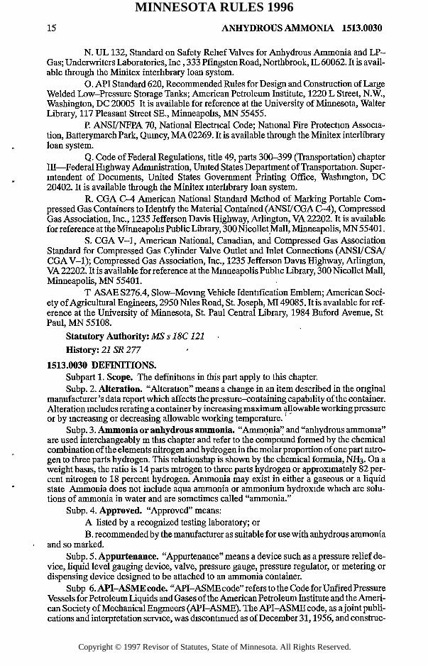
N. U L 132, Standard on Safety Relief Valves for Anhydrous Ammonia and LP- Gas; Underwriters Laboratories, In c , 333 Pfingsten Road, Northbrook, IL 60062. It is available through the Minitex mterlibrary loan system.
O. API Standard 620, Recommended Rules for Design and Construction of Large Welded Low-Pressure Storage Tanks; American Petroleum Institute, 1220 L Street, N.W., Washington, DC 20005 It is available for reference at the University of Minnesota, Walter Library, 117 Pleasant Street SE., Minneapolis, MN 55455.
P. ANSI/NFPA 70, National Electrical Code; National Fire Protection Association, Batterymarch Park, Quincy, MA 02269. It is available through the Minitex interlibrary loan system.
Q. Code of Federal Regulations, title 49, parts 300-399 (Transportation) chapter III—Federal Highway Administration, United States Department of Transportation. Superintendent of Documents, United States Government Printing Office, Washington, DC 20402. It is available through the Minitex mterlibrary loan system.
R. CGA C-4 American National Standard Method of Marking Portable Compressed Gas Containers to Identify the Material Contained (ANSI/CGA C-4), Compressed Gas Association, Inc., 1235 Jefferson Davis Highway, Arlington, VA 22202. It is available for reference at the Minneapolis Public Library, 300 Nicollet Mall, Minneapolis, MN 55401.
S. CGA V -l, American National, Canadian, and Compressed Gas Association Standard for Compressed Gas Cylinder Valve Outlet and Inlet Connections (ANSI/CSA/ CGA V -l); Compressed Gas Association, Inc., 1235 Jefferson Davis Highway, Arlington, VA 22202. It is available for reference at the Minneapolis Public Library, 300 Nicollet Mall, Minneapolis, MN 55401.
T ASAE S276.4, Slow-Movmg Vehicle Identification Emblem; American Society of Agricultural Engineers, 2950 Niles Road, St. Joseph, MI 49085. It is available for reference at the University of Minnesota, St. Paul Central Library, 1984 Buford Avenue, St Paul, MN 55108.
Statutory Authority: MS s 1 8 C 121History: 21 SR 277
1513.0030 DEFINITIONS.Subpart 1. Scope. The definitions in this part apply to this chapter.Subp. 2. Alteration. “Alteration” means a change in an item described in the onginal
manufacturer’s data report which affects the pressure-containing capability of the container. Alteration includes rerating a container by increasing maximum allowable working pressure or by increasmg or decreasing allowable working temperature.
Subp. 3. Ammonia or anhydrous ammonia. “Ammonia” and “anhydrous ammonia” are used interchangeably m this chapter and refer to the compound formed by the chemical combination of the elements nitrogen and hydrogen in the molar proportion of one part nitrogen to three parts hydrogen. This relationship is shown by the chemical formula, NH3. On a weight basis, the ratio is 14 parts mtrogen to three parts hydrogen or approximately 82 percent nitrogen to 18 percent hydrogen. Ammonia may exist in either a gaseous or a liquid state Ammonia does not include aqua ammonia or ammonium hydroxide which are solutions of ammonia in water and are sometimes called “ammonia.”
Subp. 4. Approved. “Approved” means:A listed by a recognized testing laboratory; orB. recommended by the manufacturer as suitable for use with anhydrous ammonia
and so marked.Subp. 5. Appurtenance. “Appurtenance” means a device such as a pressure relief de
vice, liquid level gauging device, valve, pressure gauge, pressure regulator, or metering or dispensing device designed to be attached to an ammonia container.
Subp 6. API-ASM E code. “API-ASME code” refers to the Code for Unfired Pressure Vessels for Petroleum Liquids and Gases of the American Petroleum Institute and the American Society of Mechanical Engmeers (API-ASME). The API-ASME code, as a joint publications and interpretation service, was discontinued as of December 31,1956, and construc
MINNESOTA RULES 1996
Copyright © 1997 Revisor of Statutes, State of Minnesota. All Rights Reserved.

1513.0030 ANHYDROUS AMMONIA 16
tion of containers to the API-ASME code has not been authorized after July 1,1961. The API-ASME code is incorporated by reference. It is not subject to frequent change and is available for reference at the University of Minnesota, Walter Library, 117 Pleasant Street SE., Minneapolis, MN 55455.
Subp. 7. ASME code. “ASME code” refers to:A. paragraphs U -68, U-69, U-200, or U-201 of Section VIII of the Boiler and
Pressure Vessel Code of the American Society of Mechanical Engineers, 1949 Edition; orB. Section VIII Division I of the Boiler and Pressure Vessel Code of the American
Society of Mechanical Engineers, 1950 Edition, through the current edition including addenda and applicable code case interpretations. The ASME code is incorporated by reference. It is not subject to frequent change and is available through the Minitex interlibrary loan system.
Subp. 8. Capacity. “Capacity” means the total volume of a container measured in standard United States gallons, unless otherwise specified.
Subp. 9 Cargo tank. “Cargo tank” means a container designed to be permanently attached to or forming a part of a highway motor vehicle, or a container not permanently attached to a highway motor vehicle, which by reason of the container’s size, construction, or attachment to a highway motor vehicle, must be loaded or unloaded without being removed from the highway motor vehicle. Cargo tank does not apply to cylinders, implements of husbandry, or containers normally used for storage.
Subp. 10. Chemical splash goggles or goggles. “Chemical splash goggles” or “goggles” mean flexible fitting protective eyewear designed to provide primary protection of the eyes and eye sockets from the splash of hazardous liquids and meeting the requirements of ANSI Z87.1, Practice for Occupational and Educational Eye and Face Protection. Chemical splash goggles or goggles does not include direct vented goggles.
Subp. 11. Commissioner. “Commissioner” means the commissioner of agriculture or an agent authorized by the commissioner.
Subp. 12. Container. “Container” means a tank, except for a cylinder and piping, used for the mobile transportation or storage of anhydrous ammonia.
Subp. 13 Cylinder. “Cylinder” means a pressure vessel of 1,000 pounds water capacity or less, constructed according to United States Department of Transportation specifications for cylinders and authorized for the transportation of ammonia. Cylinder does not include a storage tank, cargo tank, portable tank, nurse tank, or tank car.
Subp. 14. Design pressure. “Design pressure” has the meaning given to the term “maximum allowable working pressure” in the ASME code.
Subp. 15. DOT regulations. “DOT regulations” means the Hazardous Materials Regulations of the Department of Transportation (See the Code of Federal Regulations, title 49, parts 100 to 199, Transportation, including “Specifications for Shipping Containers.”) The DOT regulations are incorporated by reference. They are not subject to frequent change and are available through the Minitex interlibrary loan system.
Subp. 16. Emergency shower. “Emergency shower” means a shower unit permanently connected to a source of clean water that enables the user to have water cascading over the entire body and that otherwise meets the requirements of ANSI Z358.1, Emergency Eyewash and Shower Equipment.
Subp. 17. Eye wash u n it “Eye wash unit” means a device used to irrigate and flush the eyes with clean water. Depending upon the requirements in this chapter, the device may be a plumbed umt, permanently connected to a source of clean water, or it may be a self-contained unit, not permanently installed which must be refilled or replaced after use. An eye wash unit must meet the requirements of ANSI Z358.1, Emergency Eyewash and Shower Equipment
Subp. 18. Filling density. “Filling density” means the percent ratio of the weight of the ammonia permitted in a container to the weight of water at 60 degrees Fahrenheit that the container will hold when full. One pound of water equals 27.74 cubic inches at 60 degrees Fahrenheit. For determining the water capacity of the tank in pounds, the weight of one gallon of water at 60 degrees Fahrenheit (15.6 degrees centigrade) in air is 8.328 pounds.
MINNESOTA RULES 1996
Copyright © 1997 Revisor of Statutes, State of Minnesota. All Rights Reserved.

17 ANHYDROUS AMMONIA 1513.0030
Subp. 19. Pull face shield. “Full face shield” means a device meeting the requirements of ANSI Z87.1, Practice for Occupational and Educational Eye and Face Protection, designed to provide protection to all of the face from hazard. A full face shield may only be worn as secondary eye protection, supplementing the primary eye protection afforded by chemical splash goggles.
Subp. 20. Gas mask. “Gas mask” means an air-purifymg device with a full face piece approved by NIOSH/MSHA under Code of Federal Regulations, title 30, part II, subpart I, for use in an ammonia contaminated atmosphere in compliance with Code of Federal Regulations, title 29, part 1910 134
Subp. 21 Hydrostatic relief valve. “Hydrostatic relief valve” means a pressure relief device for liquid service designed to prevent excessive pressure due to thermal expansion when a pipe or hose is filled with liquid such as between block valves or blinds
Subp. 22. IDLH. An atmosphere is “IDLH” if it poses an immediate hazard to life or produces irreversible debilitating effects on health. The IDLH for ammonia is 300 ppm by volume.
Subp. 23. Implement of husbandry. “Implement of husbandry” means a system, including a nurse tank, with a capacity o f3,000 gallons (11.35m3) or less, or an applicator tank, used for transporting and applying anhydrous ammonia exclusively for agricultural purposes.
Subp. 24. Loading. “Loading” means the flow of ammonia from a container, such as a tank car or cargo tank, into a fixed storage tank
Subp. 25 National board inspection code. “National board inspection code” refers to the manual published by the National Board of Boiler and Pressure Vessel Inspectors which provides the rules and guidelines for inspection by a commissioned mspector of the repair, alteration, and rerating of ASME code containers after being placed into service.
Subp. 26. Permanent storage installation. “Permanent storage installation” means a system employing a stationary, fixed, container used exclusively for storage or supply
Subp. 27. Positive pressure self-contained breathing apparatus. “Positive pressure self-contained breathing apparatus” means a full face piece respirator approved by NIOSH/MSHA for respiratory protection for both entry into or escape from oxygen-deficient atmospheres or concentration of gases, or vapors which are immediately dangerous to life or health where the supply of air is carried by the wearer The air pressure inside the face piece is positive in relation to the air pressure of the outside atmosphere during exhalation and inhalation.
Subp. 28 Pressure relief valve. “Pressure relief valve” means a device designed to open to prevent an increase in internal fluid pressure in excess of a specified value due to an emergency or abnormal condition, and to close and prevent further flow after normal conditions have been restored
Subp. 29. Psig and psia. “Psig” and “psia” refer to pounds per square inch gauge and pounds per square inch absolute, respectively.
Subp 30. Repair. “Repair” means the work necessary to restore a container or system to a safe and satisfactory operating condition, provided that in all cases the container or system design must contmue to comply with this chapter or the standard in effect at the time of installation. In addition, the original design of the container or system must not be altered by the repair. Repair of a pressure container must be performed in compliance with the applicable provisions of the current edition of the National Board Inspection Code and must conform to the ASME code section and edition to which the container was constructed. Welding repair of piping must be done by a welder certified in accordance with the ASME code, Section IX, “Welding Qualifications.”
Subp. 31. Short-term exposure limit or STEL. “Short-term exposure limit” or “STEL” means a 15-minute time-weighted average exposure to an air contaminant which should not be exceeded at any time during a work day and which should not be repeated more than four times a day. Exposures at the short-term exposure limit should not occur at less than 60-minute intervals.
MINNESOTA RULES 1996
Copyright © 1997 Revisor of Statutes, State of Minnesota. All Rights Reserved.

1513.0030 ANHYDROUS AMMONIA 18
Subp. 32. System. “System” refers to an assembly of equipment consistmg of the container or containers, hoses, appurtenances, pumps, compressors, and the ammonia storage connector.
Subp 33. Transfer, fill, and charge. “Transfer,” “fill,” and “charge” may be used interchangeably and mean movement of a quantity of ammonia from one container to another contamer or cylinder, as contrasted to feeding ammonia to a use or application device.
Subp. 34. Unloading. “Unloading” means the flow of ammonia from a fixed storage tank into another contamer, such as a cargo tank or a nurse tank.
Statutory Authority: MS s 18C.121
History: 21 SR 277
1513.0040 SAFETY.Subpart 1. Training. A person required to store, handle, transfer, transport, or other
wise work with ammonia must be trained, in accordance with Code of Federal Regulations, title 29, parts 1900-1910, to understand the properties of ammonia, to become competent in safe operating practices, and to take appropriate actions in the event of a leak or an emergency.
Subp. 2. Protective gear. A person making, breaking, or testing an ammonia connection, transferring ammonia, or performing maintenance or repair on an ammoma system under pressure, must wear protective gloves and chemical splash goggles. A full face shield may be worn over the goggles. However, a face shield may not be worn as a substitute for goggles.
Subp. 3. Permanent storage installations. Permanent storage installations must have on hand, as a minimum, the equipment listed in items A to F.
A. Two full face gas masks, each with one spare ammonia canister in a readily accessible location for use in ammonia concentrations less than those that pose an IDLH.
B. One pair of protective gauntlet-style gloves of sufficient length to allow for cuffing that are impervious to ammonia.
C. One pair of protective boots impervious to ammonia.D. One protective slicker or protective pants and jacket, all impervious to ammo
nia.E. An easily accessible emergency shower and a plumbed eye wash umt or in lieu
of these, at least 150 gallons of clean water in an open top contamer.F. Chemical splash goggles or chemical splash goggles with full face shield to be
worn over the goggles.Subp. 4. Cargo tanks. A cargo tank transporting ammonia, except an implement of
husbandry, must carry the equipment listed in items A to D.A. For first aid purposes, at least five gallons (20 liters) of clean water in a contain
er designed to provide ready access to the water for flushing any area of the body contacted by ammonia.
B. One pair of protective gauntlet style gloves impervious to ammonia.C. A full face piece gas mask with an ammoma canister and at least one space can
ister.D. Chemical splash goggles, or chemical splash goggles with a full face shield to
be worn over the goggles.Subp. 5. Cylinder and DOT portable tank installations. At ammonia installations
comprising cylinders and DOT portable tanks, the employer shall provide ready access to a supply of clean, running water for emergency use, including provision for flushing of the eyes by an employee m the event of contact with ammoma, or a self-contained eye wash unit with clean water.
Statutory Authority: MS s 18C.121
History: 21 SR 277
MINNESOTA RULES 1996
Copyright © 1997 Revisor of Statutes, State of Minnesota. All Rights Reserved.

19 ANHYDROUS AMMONIA 1513.0120
1513.0100 APPLICABILITY.Parts 1513.0100 to 1513 0230 apply to this chapter unless otherwise noted.Statutory Authority: MS s 18C.121History: 21 SR 277
1513.0110 EXISTING EQUIPMENT AND SYSTEMS.Subpart 1. Containers. Part 1513.0120 does not prohibit the continued use or rein
stallation of containers constructed and maintained in accordance with, or exceeding the requirements of, the 1949,1950,1952,1956,1959,1965,1968,1971,1974,1977,1980,1983, 1986,1989,1992, and 1995 editions of the ASME code, or any revisions in effect at the time • of fabrication.
Subp. 2. Systems and components. Systems and components that were fabricated, installed, and maintained in accordance with the American National Standard K61.1, Safety Requirements for the Storage and Handling of Anhydrous Ammonia and Ammonia Solutions—Part 1 Anhydrous Ammonia, or The Agricultural Nitrogen Institute, Standard M—1, Standard for Storage and Handling of Agricultural Ammonia, in effect at the time of installation, are acceptable for continued use.
Statutory Authority: MS s 18C 121History: 21 SR 277
1513.0120 NEW CONSTRUCTION, REPAIRS, ALTERATIONS, AND ORIGINAL TEST OF CONTAINERS, OTHER THAN REFRIGERATED STORAGE TANKS.
Subpart 1. Construction and testing. Containers used with systems covered in parts1513.0300 to 1513.0380, 1513.0700 to 1513.0830, and 1513.1000 to 1513.1070 must be made of steel or other material compatible with ammonia, and tested in accordance with the current ASME code. An exception to the ASME code requirements is that construction under Table UW 12 at a basic joint efficiency of under 80 percent is not authorized.
Subp. 2. Additional requirements. Containers designed and constructed m accordance with the ASME code, other than refrigerated storage containers, shall comply with the additional requirements in items A to C.
A. The entire container must be post weld heat treated after completion of all welds in or to the shells and heads. The method employed must be as prescribed in the ASME code, except that provisions for extended time at lower temperature for post weld heat treatment are not permitted. Implements of husbandry do not require post weld heat treatment if they are fabricated with hot formed heads or with cold formed heads that have been stress relieved.
B. Welded attachments to pads may be made after post weld heat treatment.C. Steels used in fabricating pressure containing parts of a container must not ex
ceed a specified tensile strength of 70,000 psi (does not apply to parts 1513.0600 to1513.0640,1513.0700 to 1513.0830 and 1513.0900 to 1513.0930), except implements of husbandry may be fabricated from steel having a specified tensile strength of 75,000 psi.
Subp. 3. Inspectors. All containers, except refrigerated storage tanks with a design pressure of 15 psig and less, and cylinders and containers covered in parts 1513.0600 to1513.0710 must be inspected by a person who holds a valid National Board commission as a commissioned inspector or as an owner-user inspector as defined in the National Board Inspection Code.
Subp. 4. Certified welder. Welding for the repair or alteration of a pressure container must be performed in compliance with the applicable provisions of the current edition of the National Board Inspection Code. All repair or alteration must conform to the ASME code section and edition to which the container was constructed.
Statutory Authority: MS s 18C.121
BASIC RULES
History: 21 SR 277
MINNESOTA RULES 1996
Copyright © 1997 Revisor of Statutes, State of Minnesota. All Rights Reserved.

1513.0130 ANHYDROUS AMMONIA 2 0
1513.0130 LOCATION OF CONTAINERS.Subpart 1. Site selection considerations. The location for a storage container must be
selected considering the potential physiological and environmental effects of ammonia on the surroundings adjacent to the proposed site. Containers must be located outside of buildings except in buildings or sections of buildings especially approved for the purpose.
Subp. 2. Distance from potable water source. Storage containers installed after September 3,1996, must be located at least 50 feet from a dug well or other source of potable water, unless the container is a part of a water treatment installation.
Subp. 3. Distance from other property and dwellings. Containers installed after September 3,1996, must be located in accordance with the following:
A. Containers with a nominal capacity of 100,000 gallons or less may not be located less than 50 feet from the line of adjoining property or from the near side of a public roadway or mainline of railroad; and 400 feet from the nearest occupied dwelling or dwelling intended to be occupied, place of public assembly, or confined resident institution.
B. Containers with a nominal capacity of greater than 100,000 gallons may not be located less than 50 feet from the lme of adjoining property, from the near side of a public roadway or mainline of railroad; and 1,000 feet from the nearest occupied dwelling or dwelling intended to be occupied, place of public assembly, or confined resident institution.
Subp. 4. Emergency accessibility. Container storage areas must be accessible to emergency vehicles and personnel
Subp. 5. Clear areas. Areas within ten feet of a storage container must be maintained clear of dry grass and weeds and other combustible materials and matenals not required for the operation of the system.
Statutory Authority: MS s 18C.121History: 21 SR 277
1513.0140 MARKINGS OF NONREFRIGERATED CONTAINERS AND SYSTEMS OTHER THAN DOT CONTAINERS.
Subpart 1. Nameplates. Each system nameplate must be made of a noncorroding metal permanently attached to the system by continuous welding around its perimeter and located so as to be readily accessible for inspection. Nameplates must be maintained in legible condition and include markings as prescribed in subpart 2.
Subp. 2. Information required. Each container or system covered in parts 1513 0300 to 1513.0380 and 1513.0700 to 1513.0930, except “ton containers” and “cylinders,” and parts 1513.1000 to 1513.1070 must be marked as specified by paragraphs UG-116 and UG-118(b) of the ASME code or as follows:
A. with an identification number issued by the commissioner;B. with the certification date;C. with the maximum allowable working pressure;D. with the wall thickness of the container shell and heads in inches or millimeters,
andE. with the water capacity of the contamer in pounds or kilograms, or United States
standard gallons or cubic meters (m3) at 60 degrees Fahrenheit (15 6 degrees centigrade). Items A to E must be determined and documented, on forms provided by the commissioner, by a company that holds a valid R-stamp, in compliance with the current edition of the National Board Inspection Code. Storage containers installed prior to September 3,1996, are not required to be renameplated. If needed, nurse tanks and applicator tanks must be rename- plated by September 3,1998.
Subp. 3 Liquid level gauge. Each container or system covered m parts 1513.0300 to1513.0380 and 1513.0700 to 1513 0930, except cylinders, and parts 1513.1000 to 1513.1070 must be fitted with a liquid level gauge indicating the maximum level to which the container may be filled with liquid anhydrous ammonia at temperatures between 20 degrees Fahrenheit and 100 degrees Fahrenheit, except on containers provided with fixed maximum level indicators, such as fixed length dip tubes or containers that are filled by weight. Marks must be m increments of not more than 20 degrees Fahrenheit. Part 1513.0190, subpart 3, contams requirements for thermometer wells and thermometers.
MINNESOTA RULES 1996
Copyright © 1997 Revisor of Statutes, State of Minnesota. All Rights Reserved.

2 1 ANHYDROUS AMMONIA 1513.0150
Subp. 4. Container openings. All nonrefrigerated system openings and appurtenances except for pressure relief valves, pressure indicating devices, thermometer wells, or liquid level indicators must be marked, stenciled, tagged, or decaled to indicate whether the opening is in contact with the liquid or vapor phase when the container is filled to the maximum allowable filling density. If paint is used to identify the phases, liquid must be orange and vapor yellow. The valves and lines must be painted to within three feet, except for hose, of the system openings.
Statutory Authority: MS s 1 8 C 121History: 21 SR 277
1513.0150 CONTAINER APPURTENANCES.Subpart 1. Approval. All appurtenances of each system must be approved in accord
ance with part 1513.0030, subpart 4. ' ,Subp. 2. Materials and design. All appurtenances must be designed for not less than
the maximum working pressure of that portion of the system on which they are installed. All appurtenances must be fabricated from materials proved suitable for anhydrous ammoma service. , •
Subp. 3. Shut-off valves. All connections to containers except those for pressure relief devices, thermometer wells, liquid level gauging devices, or those fitted with a No. 54 (0.055 inch) drill size orifice, or those plugged, must have shut-off .valves located as close to the container as practical, with the valve installed so that the. product m the tank is under the disc holder when the valve is closed.The shut-off valves at the risers must also be installed so that the product in the piping is under the disc holder when the valve is closed. Any other shut-off valves in the piping may be installed either direction, unless the manufacturer specifies otherwise.
Subp 4. Excess flow valves. Excess flow valves must close automatically at the rated flows of vapor or liquid as specified by the manufacturer. The connections and line, including valves and fittings being protected by an excess flow valve, must have a greater capacity than the rated flow of the excess flow valve.
Subp. 5 Exceptions.A Liquid level gauging devices that require bleedmg of the product to the atmo
sphere, and which are so constructed that outward flow will not exceed that passed by a No. 54 (0.055 inch) drill size opening, need not be equipped with excess flow valves.
B. An opening in a container to which a pressure gauge connection is made need not be equipped with an excess flow valve, if such an opening is not larger than No. 54 (0.055 inch) drill size.
Subp. 6. Installation. If an excess flow or back pressure check valve is required by this part, it must be installed directly in the container opening or at a point outside as close as practicable to where the line enters the container In the latter case the installation must be made in such a manner that any undue strain beyond the excess flow or back pressure check valve will not cause breakage between the container and the valve. >
Subp. 7. By-pass. An excess flow valve must be designed with a by-pass, not to exceed a No. 60 (0.040 inch) drill size opening, to allow equalization of pressures.,
Subp. 8. Integral excess flow valve. A shut-off valve with an integral excess flow valve must be designed for proper installation in a container opening so that the excess flow valve will close in the event that the valve body, extending above the coupling, is sheared or broken off. - ,
Subp. 9. Markings. An excess flow valve must be plainly and permanently marked with the name or trademark of the manufacturer, the catalog number, and the rated capacity.
Subp. 10. Positive shut-off valve. Each liquid filling connection on nonrefrigerated containers must have a positive shut-off valve in conjunction with either a back-pressure check valve or an excess flow valve. Vapor connections on nonrefrigerated containers must have a positive shut-off valve together with an excess flow valve. The back-pressure check valves or excess flow valves must be installed in the facility prior to the positive shut-off valves.
MINNESOTA RULES 1996
Copyright © 1997 Revisor of Statutes, State of Minnesota. All Rights Reserved.

Subp. 11. Quick opening valves. Quick opening (1/4 turn) valves must not be used on transfer lines
Statutory Authority: MS s 18C.121History: 21 SR 277
1513.0160 PIPING, TUBING, AND FITTINGS.Subpart 1. Material and design. Piping, tubing, and fittings must be made of steel or
other material suitable for anhydrous ammonia service and must be designed for a pressure not less than the maximum pressure to which they may be subjected in service.
Subp 2. Standards. Piping must be supported in accordance with good piping practices and provisions must be made as necessary for expansion, contraction, impact, vibration, and settling. Piping must conform to ANSI/ASME B31.3, American National Standard for Chemical Plant and Petroleum Refinery Piping, except ANSI/ASME B31.5, American National Standard for Refrigeration Piping, may be used for refrigeration piping systems within its scope.
Subp. 3. Pipe connections. Piping used on nonrefrigerated systems must be at least ASTM A-53 Grade B seamless or Electric Resistance Welded Pipe.-Pipe jomts must be threaded, welded, or flanged. Pipe must be at least Schedule 40 when joints are welded, or welded and flanged. Pipe must be at least schedule 80 when joints are threaded. Brass, copper, or galvanized steel pipe or tubing may not be used. Threaded nipples must be seamless. Welding must be done by a welder certified in accordance with the ASME code, Section IX, “Welding Qualifications.” Tubing joints must be flareless or compression type fittings complying with ANSI/SAE J513f,' ANSI/ASME B31.3, or ANSI/ASME 31.5.
Subp. 4. Minimum working pressure. All metal flexible connections for permanent nonrefrigerated installations shall have a minimum working pressure o f250 psig (safety factor of four).
Subp. 5. Materials for fittings and valves. Cast iron fittings may not be used Those parts of valves which are subjected to gas pressure must be made of steel, ductile (nodular) iron, or malleable iron. Valves in this case include shut-off valves, excess flow valves, back check valves, emergency shut-off valves, and remotely controlled valves. Ductile iron must meet the requirements of ANSI/ASTM A395 and malleable iron the requirements of ANSI/ASTM A47.
Subp. 6. Protection from damage. Adequate provisions must be made to protect all exposed piping from physical damage that might result from impact by moving machinery, automobiles, trncks, or any other equipment at the facility.
Subp. 7. Joint compounds. Joint compounds must be resistant to ammonia at the maximum pressure and temperature to which they may be subjected in service.
Subp. 8. Testing. After assembly, all piping, hose, and tubing must be tested and proved to be free from leaks at a pressure not less than the normal operating pressure of the system.
Statutory Authority: MS s 18C.121History: 21 SR 277
1513.0170 HOSE SPECIFICATIONS.Subpart 1. Standards. Hose used in ammonia service and subject to container pressure
must conform to the American National Standard RMA IP-14, Specifications for Anhydrous Ammonia Hose.
Subp. 2. Pressures. Hose subject to container pressure must be designed for a minimum working pressure o f350 psig and a minimum burst pressure of 1,750 psig. Hose assemblies, when made up, must be capable of withstanding a test pressure of 500 psig.
Subp. 3. Design o f hoses and connections. Hose and hose connections located on the low pressure side of flow control, or pressure reducing valves on devices discharging to atmospheric pressure, must be designed for the maximum low side working pressure. All connections must be designed, constructed, and installed so that there will be no leakage when connected. Shut-off valves on the end of liquid and vapor transfer hoses must be equipped with bleed valves to enable the operator to bleed off pressure before disconnecting the hoses.
Subp. 4. Transfer hose. If a transfer hose is not drained of ammonia upon completion of transfer operations, the hose must be equipped with an approved shut-off valve at the dis
1513.0150 ANHYDROUS AMMONIA 22
MINNESOTA RULES 1996
Copyright © 1997 Revisor of Statutes, State of Minnesota. All Rights Reserved.

23 ANHYDROUS AMMONIA 1513.0180
charge end. Provision must be made to prevent excessive hydrostatic pressure in the hose under part 1513.0180, subpart 11.
Subp. 5. Information on hose. All hose that is one-half inch outside diameter or larger and that is used in ammonia service and subject to container pressure, must have etched, cast, or impressed at five foot intervals on the outer hose cover the following information:
A. anhydrous ammonia;B. XXX psig (maximum working pressure);C. manufacturer’s name or trademark; andD. year of manufacture or expiration.
Statutory Authority: MS s 18C.121History: 21 SR 277
1513.0180 PRESSURE RELIEF DEVICES.Subpart 1. Standards. Every container used in systems covered by parts 1513.0300 to
1513.0380 and 1513.1000 to 1513.1070 must be provided with one or more pressure relief valves of the spring-loaded type conforming with the applicable requirements of U L 132, Standard on Safety Relief Valves for Anhydrous Ammonia and LP-Gas.
Subp. 2. Direct contact with vapor space. Pressure relief valves with a rating not greater than the designed working pressure of the container or appurtenances must be in direct contact with the vapor space of the container.
Subp. 3. Discharge. The discharge from pressure relief valves must be vented away from the contamer, upward and unobstructed to the atmosphere. Pressure relief valves shall not be painted or contain other foreign substances. All pressure relief valve discharge openings shall have rain caps that will allow free discharge of the vapor and prevent the entrance of water. Provision must be made for draining condensate which may accumulate. The rate of the discharge must be in accordance with part 1513.1100.
Subp. 4. S tart to discharge. Container pressure relief valves with relation to the design pressure of the contamer must be set to start to discharge as follows:
Containers Minimum MaximumPercent Percent
ASME U-68,U-69 110 125
ASME U-200,U-201 95 100
ASME 1952,1956,1959,1962,1965,1968,1971,1974,1977,1980,1983,1986,and 1989 95 100
API-ASME 95 100
U.S. Coast Guard (As required by USCG regulations)
DOT (As required by DOT regulations)
Subp. 5. Discharge rates. Pressure relief valves used on containers covered by parts1513.0300 to 1513.0380 and 1513.1000 to 1513.1070 shallbe constructed to discharge at not less than the rates required in subpart 3 before the pressure is in excess of 120 percent (not includmg the ten percent tolerance referred to in subpart 4) of the maximum permitted start to discharge pressure setting of the device.
Subp 6. Tampering. Pressure relief valves must be so arranged that the possibility of tampering will be minimized. If the pressure setting adjustment is external, the relief valves must be provided with means for sealing the adjustment.
Subp. 7. Shut-off valve locations. Shut-off valves must not be installed between the pressure relief valves and the containers or systems covered by parts 1513.0300 to
MINNESOTA RULES 1996
Copyright © 1997 Revisor of Statutes, State of Minnesota. All Rights Reserved.

1513.0180 ANHYDROUS AMMONIA 2 4
1513.0380 and 1513.1000 to 1513.1070 except that a shut-off valve may be used where the > arrangement of the shut-off valve is such as always to afford the full capacity flow specified in subpart 3 through a nonisolated pressure relief valve which must remain operative.
Subp. 8. Marking. Each pressure relief valve used with systems covered by parts1513.0300 to 1513 0380 and 1513.1000 to 1513.1070 must be plainly and permanently marked as follows:
A with the letters “AA” or the symbol “NH3”;B. the pressure in pounds per square inch gauge at which the valve is set to start to
discharge;C. the rate of discharge of the valve in cubic feet per minute of air at 60 degrees
Fahrenheit and atmospheric pressure; andD. the manufacturer’s name and catalog number.
Subp. 9. Restriction of flow capacity. The flow capacity of the pressure relief valve must not be restricted by any connection to it on either the upstream or downstream side.
Subp. 10. Data; testing. The manufacturer or supplier of a pressure relief valve manifold must publish complete data showing the flow rating through the combined assembly of the manifold with pressure relief valves installed. The manifold flow rating must be determined by testing the manifold with all but one valve discharging. If one or more openings have restnctions not present in the remaining openings, the restricted opening or openings, or those having the lowest flow, must be used to establish the flow rate marked on the manifold nameplate. The marking must be in accordance with subpart 8 for individual valves.
Subp. 11. Hydrostatic relief valve. A hydrostatic relief valve or equivalent, with a rating of 350-400 psig, must be installed in each section of piping, including hose, in which liquid ammonia can be isolated between shut-off valves to relieve the pressure which could develop from the trapped liquid. In no case may the hydrostatic relief valve or equivalent setting exceed system design pressure. ■ '
Subp. 12. Discharge opening. The discharge openmg from any pressure relief valve may not terminate inside any building or below the highest roof line of a building.
Subp. 13. Periodic inspection. A pressure relief device must be subject to a periodic visual external inspection by the facility operator to determine that it:
A. is free of evidence of tampering, damage, corrosion, or foreign matter that might prevent proper operation;
B. is free of leakage when subject to pressures below the minimnm allowable start to discharge setting;
C. has a properly secured rain cap or other device to avoid entry of moisture or other matter into the relief valve outlet; and
D. has an open weep hole to permit moisture to escapeSubp. 14. Replacement. No nonrefrigerated container pressure relief valve may be
used over five years after the date of installation of the pressure relief device. Records must be maintained which identify each container and indicate the date of installation for each contamer pressure relief device.
Statutory Authority: MS s 18C.121History: 21 SR 277
1513.0190 FILLING DENSITIES.Subpart 1. Nonrefrigerated containers. The maximum filling densities for nonrefrig-
erated containers are- 1 „Aboveground Underground
(1) Uninsulated - 56%* 58%
(2) Insulated 57%
(3) DOT containers and cylinders shall be filled in accordance with DOT regulations.
MINNESOTA RULES 1996
Copyright © 1997 Revisor of Statutes, State of Minnesota. All Rights Reserved.
25 ANHYDROUS AMMONIA 1513.0200
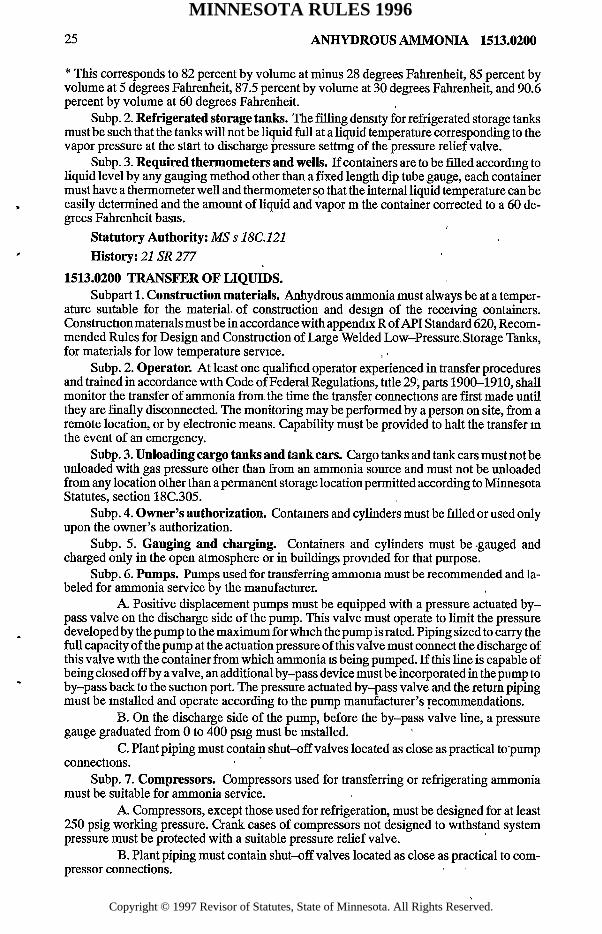
* This corresponds to 82 percent by volume at minus 28 degrees Fahrenheit, 85 percent by volume at 5 degrees Fahrenheit, 87.5 percent by volume at 30 degrees Fahrenheit, and 90.6 percent by volume at 60 degrees Fahrenheit.
Subp. 2. Refrigerated storage tanks. The filling density for refrigerated storage tanks must be such that the tanks will not be liquid full at a liquid temperature corresponding to the vapor pressure at the start to discharge pressure settmg of the pressure relief valve.
Subp. 3. Required thermometers and wells. If containers are to be filled according to liquid level by any gauging method other than a fixed length dip tube gauge, each container must have a thermometer well and thermometer so that the internal liquid temperature can be easily determined and the amount of liquid and vapor m the container corrected to a 60 degrees Fahrenheit basis.
Statutory Authority: MS s 18C.121History: 21 SR 277
1513.0200 TRANSFER OF LIQUIDS.Subpart 1. Construction materials. Anhydrous ammonia must always be at a temper
ature suitable for the material, of construction and design of the receiving containers. Construction matenals must be in accordance with appendix R of API Standard 620, Recommended Rules for Design and Construction of Large Welded Low-Pressure, Storage Tanks, for materials for low temperature service.
Subp. 2. Operator. At least one qualified operator experienced in transfer procedures and trained in accordance with Code of Federal Regulations, title 29; parts 1900-1910, shall monitor the transfer of ammonia from the time the transfer connections are first made until they are finally disconnected. The monitoring may be performed by a person on site, from a remote location, or by electronic means. Capability must be provided to halt the transfer in the event of an emergency.
Subp. 3. Unloading cargo tanks and tank cars. Cargo tanks and tank cars must not be unloaded with gas pressure other than from an ammonia source and must not be unloaded from any location other than a permanent storage location permitted according to Minnesota Statutes, section 18C.305.
Subp. 4. Owner’s authorization. Containers and cylinders must be filled or used only upon the owner’s authorization.
Subp. 5. Gauging and charging. Containers and cylinders must be -gauged and charged only in the open atmosphere or in buildings provided for that purpose.
Subp. 6. Pumps. Pumps used for transferring ammonia must be recommended and labeled for ammonia service by the manufacturer.
A. Positive displacement pumps must be equipped with a pressure actuated bypass valve on the discharge side of the pump. This valve must operate to limit the pressure developed by the pump to the maximum for which the pump is rated. Piping sized to carry the full capacity of the pump at the actuation pressure of this valve must connect the discharge of this valve with the container from which ammonia is being pumped. If this line is capable of being closed off by a valve, an additional by-pass device must be incorporated in the pump to by-pass back to the suction port. The pressure actuated by-pass valve and the return piping must be installed and operate according to the pump manufacturer’s recommendations.
B. On the discharge side of the pump, before the by-pass valve line, a pressure gauge graduated from 0 to 400 psig must be installed.
C. Plant piping must contain shut-off valves located as close as practical to pump connections.
Subp. 7. Compressors. Compressors used for transferring or refrigerating ammonia must be suitable for ammonia service.
A. Compressors, except those used for refrigeration, must be designed for at least 250 psig working pressure. Crank cases of compressors not designed to withstand system pressure must be protected with a suitable pressure relief valve.
B. Plant piping must contain shut-off valves located as close as practical to compressor connections.
MINNESOTA RULES 1996
Copyright © 1997 Revisor of Statutes, State of Minnesota. All Rights Reserved.

C A pressure relief valve large enough to discharge the full capacity of the compressor mustbe connected to both sides before any shut-off valve.
D. Compressors must have pressure gauges at both the suction and discharge sides graduated from 0-400 psig.
E. Adequate means, such as a drainable liquid trap, must be provided on the compressor suction to minimize the entry of liquid into the compressor.
F. Where necessary to prevent contamination, an oil separator must be provided on the discharge side of the compressor.
Subp. 8. Protection of lines. Loading lines on nonrefrigerated containers must be protected by a backflow check valve or other suitable protection for liquid and an excess flow valve or other suitable protection for vapor. Unloading lines on nonrefrigerated containers must be protected by excess flow valves or other suitable protection. Piping must be sized so as not to restrict flow rates to the extent that protective devices will not function. The backflow check valves, excess flow valves, or equivalent protection mustbe installed in the facility piping so that any break will occur on the side of the hose or swivel connection
Stationary storage installations must have approved automatically operated emergency shut-off valves, weakness or shear fittings, or other suitable protection installed in the fixed piping of the transfer system prior to where the hose or swivel piping is attached to the fixed piping. This requirement does not apply to the liquid barge, truck, and tank car loading or
- unloading lines, or a line feeding a fixed process system. Emergency shut-off valves must remain closed when the facility is not m use. The emergency shut-off valves, weakness or shear fittings, or equivalent protection must be installed in the facility piping so that any break will occur on the side of the hose or swivel connection. This must be completed by September 3,1998.
Subp. 9. Meters. Meters used for the measurement of liquid anhydrous ammonia for retail sale must be recommended and labeled for ammonia service by the manufacturer.
A. Liquid meters must be designed for minimum working pressure of 250 psig.B. The metering system must incorporate devices that will prevent the inadvertent
measurement of vapor.Statutory Authority: MS s 18C.121History: 21 SR 277
1513.0210 LIQUID LEVEL GAUGING DEVICES.Subpart 1. Required. A container must be equipped with a liquid level gauging device
designed for use with ammonia.Subp. 2. Arrangement. A gauging device must be arranged so that the maximum liq
uid level to which the container is filled is readily determined and be installed according to part 1513.0140, subpart 3.
Subp. 3. Gauging devices requiring bleeding. Except as provided in parts 1513 1000 to 1513.1070, gauging devices that require bleeding of the product to the atmosphere such as rotary tube, fixed tube, and slip tube devices, must be designed so that the maximum opening of the bleed valve is not larger than No. 54 (0.055 mch) drill size unless provided with an excess flow valve.
Subp. 4. Design pressure. Gauging devices must have a design pressure equal to or greater than the design pressure of the container on which they are installed.
Subp. 5. Fixed maximum liquid level gauges. Fixed maximum liquid level gauges must be designed and installed to indicate a volumetnc level not to exceed 85 percent of the container’s water capacity. This does not apply to refrigerated storage.
Subp. 6. Columnar gauge glasses. Gauge glasses ofthe columnar type are restncted to stationary nonrefrigerated storage installations. They must be equipped with shut-off valves having metallic hand wheels, with excess flow valves, and with extra heavy glass adequately protected with a metal housing applied by the gauge manufacturer. They must be shielded against the direct rays of the sun.
Statutory Authority: MS s 18C.121
1513.0200 ANHYDROUS AMMONIA 26
History: 21 SR 277
MINNESOTA RULES 1996
Copyright © 1997 Revisor of Statutes, State of Minnesota. All Rights Reserved.

2 7 ANHYDROUS AMMONIA 1513.0330
1513.0220 PAINTING OF CONTAINERS.Aboveground uninsulated containers must have a reflective surface maintained in good
condition. White is recommended for painted surfaces, but other colors having similar reflecting characteristics are acceptable. * ' ’ ‘
Statutory'Authority: M S s 18C.121 ' ' \. History: 22 SR277 ■ ;■ *
1513:0230 ELECTRICAL EQUIPMENT AND WIRING. “■'' Subpart 1. Ammonia installations. Electrical equipment and wiring for use in ammo
nia installations must be general purpose or weather resistant as appropriate.Subp. 2. High concentrations of ammonia. Where concentrations of ammonia in air
in excess of 16 percent by volume are likely to be encountered, electrical equipment and wiring must be installed to comply with the requirements for use in hazardous locations, Class I, Group D, of NFPA 70, National Electrical Code, Articles 500 and 501. .
Statutory Authority: MS s 18C.121 , \H istory:21 S R 277 ■ ‘
SYSTEMS USING STATIONARY, PIER-MOUNTED, OR SKID-MQUNTED ABOVEGROUND OR UNDERGROUND, NONREFRIGERATED STORAGE
1513.0300 APPLICABILITY.Parts,1513.0300 to 1513.0380 apply to,stationary, pier-mounted, skid-mounted; abo-,
veground or, underground, nonrefrigerated storage installations using containers oilier than , those constructed in accordance with United States Department of Transportation specifications. All basic rules of parts 1513.0100 to 1513.0230 apply to parts 1513.0300 to 1513.0380 unless otherwise noted.
Statutoiy Authority: MS s 18C.121History: 21 S R 277 !" x’ - ‘ * ' “ ( , '
1513.0310 DESIGN PRESSURE AND CONSTRUCTION O ? CONTAINERS.The minimum design pressure for nonrefrigerated containers is 250 psig or in accordT
ance.with part 1513.0110, subpart 2. , ; •, " 1 ,, , u • ->•*• Statutory Authority: MS s 18C.121 * ‘ ' ' '
History: 21 SR 277, ' ^1513.0320 CONTAINER VALVES, ACCESSORIES, AND DISCHARGE CONNECTIONS.
Subpart 1. Excess flow valves. All vapor and liquid connections, except for pressure relief valves and those specifically exempted in part 1513.0150, subparts"5 and 6, must be equipped with approved excess" flow valves. Back-pressure check valves are1 acceptable in container filling connections. Alternatively, vapor and liquid connections covered by this- subpart may be fitted with quick-closing internal valves which, except during operating periods, shall remain closed. If internal valves are not practical, external quick-closing valves may be used according to part 1513.0150, subpart 6, and with appropriate protection as required in part 1513.0370. '
Subp. 2. Pressure gauge. Each- storage contamer must be provided with a pressure gauge graduated from 0 to 400 psig. Gauges must be designated for use in ammonia service.
Subp. 3. Vapor equalizing connection. All containers must be equipped with a vapor equalizing connection. ' - - '
Statutory Authority: MS s 18C.121 1History: 21 SR 277- . , . r ,
1513.0330 PRESSURE RELIEF DEVICES. J :Subpart 1. Required valves. A container must be provided with one or more pressure
relief valves of spring-loaded or equivalent type which comply with items A to C.
MINNESOTA RULES 1996
Copyright © 1997 Revisor of Statutes, State of Minnesota. All Rights Reserved.

1513.0330 ANHYDROUS AMMONIA 28
A. Relief valves must be installed in a manifold so that they can be replaced while the container remains pressurized. , , , .
. > B. The discharge from pressure, relief valves must be vented away from the container, upward and unobstructed to the open air to an area such that persons, property, and the environment will not be harmed. Vent pipes must not be restrictive or smaller in size than the pressure relief valve outlet connection. All pressure relief valves must have rain caps that will allow free discharge of the vapor and prevent the entrance of water. Provision must be made for draining condensate which may accumulate. * , , ,
C. Noncorrosive vent pipes from two or more pressure relief devices located on the same unit, or similar lines from one or more different units, may be run into a common header, provided the cross-sectional area of the header is at least equal to the sum of the cross-sectional areas of the individual vent pipes.
Subp. 2. Rate o f discharge. The rate of discharge of spring-loaded pressure relief valves installed on underground containers may be reduced by not more than 30 percent o f , the rate of discharge specified in part 1513.1100. Containers so protected must not be uncovered after installation until the liquid ammonia has been removed. Containers which may contain liquid ammonia before being installed underground, and before being completely covered with earth, are to be considered aboveground containers when determining the rate of discharge requirements of the pressure relief valves.
Subp. 3. Discharge from underground installations. On underground installations where there is a probability of the manhole or housing becoming flooded, the discharge from vent lines must be located above the high water level. Manholes or housings must-be provided with ventilated louvers'or their equivalent, the area of such openings equaling or exceeding the combined discharge areas of the pressure relief valves and vent line's which discharge their content into the manhole housing. :
StatutoryAuthority: MS s 18C.121History: 21 SR 277 _ ,
1513.0340 INSTALLATION OF STORAGE CONTAINERS. ,Subpart 1. Footings, foundations, and subparts. Containers installed aboveground
must be provided with reinforced concrete footings and foundations or structural steel supports mounted on reinforced concrete foundations. In either case, the reinforced concrete foundations or footing must extend below the established frost line and be of sufficient width and thickness to support the total weight of the containers and contents adequately. The foundation must maintain the lowest point of the tank not less than. 18 inches above the ground. Floating type foundations must also be acceptable if the foundations are designed to adequately support the tank, contents, and piping according to part ,1513.0160. , ’
Subp. 2. Horizontal aboveground containers. Horizontal aboveground.contairiers mustbe mounted on foundations so as to permit expansion and contractions. A container must be,supported to prevent the concentration of excessive loads. The bearing afforded by the saddles must extend over at least one-third of the circumference of the shell. Suitable means for preventing corrosion must be provided on that portion of the contamer in contact with the foundations or saddles.
Subp. 3. Buried containers. Containers buried underground must be placed so that the top of the container is at least one foot below the surface. It is not necessary to cover the portion of the container to which a manhole and other connections are affixed. If necessary to prevent floating, containers must be securely anchored or weighted.
, Subp. 4. Corrosion resistance. As a minimum, an underground container must be set on firm earth or another firm foundation, and must be surrounded by at least six inches of noncorrosive, inert materials, such as soft earth, sand, or gravel well compacted into place. As a further means of resisting corrosion, the container and its piping, prior,to placement in the ground, must be provided with the following: '
A. a suitable protective coating applied after proper surface preparation according to the coating manufacturer’s recommendations; ,■ , .> ' , \ "
i B. cathodic protection; and ;C. electrical isolation of the container from ancillary equipment.
MINNESOTA RULES 1996
Copyright © 1997 Revisor of Statutes, State of Minnesota. All Rights Reserved.
2 9 ANHYDROUS AMMONIA 1513.0380
Corrosion-resistant materials of construction may be used as an option. A coated container must be lowered into place in a manner to prevent abrasion or damage to the coating.
Subp. 5. Separation. The horizontal distance between aboveground and underground containers of over 1,200 gallons capacity must be at least five feet.
Subp. 6. Protection against flotation. Secure anchorage or adequate pier height must be provided agamst container flotation wherever sufficiently high flood water might occur.
Statutory Authority: M S s 18C.121 History: 21 SR 277
1513.0350 REINSTALLATION OF CONTAINERS.Subpart 1. Testing. Containers, once installed underground shall not later be reinstalled
aboveground or underground, unless they successfully withstand hydrostatic pressure retests at the pressure specified for the original hydrostatic test as required by the ASME code under which the tank was constructed, and show no evidence of serious corrosion.
Subp. 2. Coating; valves. If a container is reinstalled underground, the corrosion resistant coating, if used, must be put in good condition, according to part 1513 0340, subpart 4. If a container is reinstalled aboveground, pressure relief devices or gauging devices must comply with parts 1513.0180,1513.0210, and 1513.0330 as applicable to aboveground containers.
Statutory Authority: MS s 18C.121 History \2 1 S R 2 7 7
1513.0360 MARKING CONTAINERS.Each container or group of containers must be marked on at least two sides that are vis
ible with the words, “ANHYDROUS AMMONIA,” and “INHALATION HAZARD,” in sharply contrasting colors with letters not less than four inches high, or in compliance with DOT regulations. Each container or group of containers must also be marked with the UN identification number for ammonia, 1005, on each side
Each container must be labeled in a conspicuous manner with the appropriate grade or guaranteed analysis of the contents of the storage container
Each container or group of containers which is installed underground must have a sign bearing marks and labeling as required in this part located adjacent to the'cover described in part 1513.0370.
Statutory Authority: MS s 18C.121 History: 21 SR 277 ;
1513.0370 PROTECTION OF CONTAINER AND APPURTENANCES.Containers and appurtenances must be located or protected by suitable barriers so as to
avoid damage by trucks or other vehicles. Main container shut-off valves and riser hose end valves must be kept closed and locked when the installation is unattended. If the facility is protected against tampering by fencing, valve locks are not required.
All connections to underground containers must be located within a dome, housing, or manhole fitted with a substantial removable cover.
Storage containers need not be electrically grounded.Statutory Authority: MS s 18C.121 History: 21 SR 277
1513.0380 IDENTIFICATION.A legible sign must be displayed on the premises at which a storage system is located, so
as to be readily visible to emergency response personnel, stating the name, address, and telephone number of the nearest representative, agent, or owner of the storage system.
Statutory Authority: MS s 18C.121History: 21 SR 277
MINNESOTA RULES 1996
Copyright © 1997 Revisor of Statutes, State of Minnesota. All Rights Reserved.
1513.0400 ANHYDROUS AMMONIA 30
1513.0400 REFRIGERATED STORAGE.Parts 1513.0400 to 1513.0500 apply specifically to systems using tanks for the storage
of anhydrous ammonia under refrigerated conditions. Parts 1513.0100 to 1513.0230 apply unless otherwise stated.
Statutory Authority: MS s 18C.121History: 21SR 277
1513.0410 DESIGN OF TANKS.Subpart 1. Economical design. Tanks may be designed for any storage pressure de
sired as determined by economical design of the refrigerated system.Subp. 2. Design tem perature. The design temperature must be the mimmum tempera
ture to which the container will be refrigerated and must be so designated.Subp. 3. Design pressure over 15 psig. Containers with a design pressure exceeding 15
psig must be constructed according to part 1513.0120 and the material must be selected from those listed in API Standard 620, Recommended Rules for Design and Construction of Large, Welded, Low-Pressure Storage Tanks, Tables 2.02, R.2.2, R.2.3, or R.2.4.
Subp. 4. Design pressure of 15 psig or less. Tanks with a design pressure of 15 psig and less must be constructed according to the general requirements of API Standard 620, including Appendix R.
Subp. 5. Certain metals. When austenitic stainless steels or nonferrous metals are used, the ASME code must be used in selection of materials for use at the design temperature.
Statutory Authority: MS s 18C.121History: 21 SR 277
1513.0420 INSTALLATION OF STORAGE TANKS ABOVEGROUND.Subpart 1. Foundations. Tanks must be supported on noncombustible foundations de
signed to accommodate the type of tank being used.Subp. 2. W ater protection. Adequate protection against flotation or other water dam
age must be provided wherever high flood water might occur.Subp. 3. Freezing protection. Tanks storing product at less than 32 degrees Fahrenheit
must be supported in such a way, or heat must be supplied, to prevent the effects of freezing and subsequent frost heaving of the soil.
Subp. 4 Liquid containment system. The area surrounding a refrigerated tank or group of tanks must be provided with drainage or must be diked or provided with other secondary containment systems to prevent accidental discharge of liquid from spreading to uncontrolled areas.
Subp 5. Drainage. If drainage is employed, a slope of not less than one percent mustbe provided The drainage system must terminate in an impounding basin havmg a capacity as large as the largest tank served.
Subp. 6. Rain water. Provision must be made for the drainage of rain water from the dike or impounding area. Drainage must be provided with a positive means to stop the flow
Subp. 7. Dike capacity. If a dike is employed, the capacity of the diked enclosure must be 110 percent of the capacity of the largest tank served. When computing the volume of the dike, allowance must be made for the volume displaced by all other containers in the diked area.
Subp. 8. Walls. The walls of a diked enclosure or the wall of an impounding basin used m a drainage system must be of earth, steel, concrete, or other suitable material designed to be liquid tight and to withstand the hydrostatic pressure and temperature. Earth walls must have a flat top at least two feet wide. The slope must be stable and consistent with the angle of repose of the earth used.
Subp. 9. Grading. The ground in an impounding basin or withm a diked enclosure, should be graded so that small spills or the early part of a large spill will accumulate at one side or comer, thereby contacting only a relatively small area of ground and exposing a relatively small area of ground and exposmg a relatively small surface area for heat gain. Shal
MINNESOTA RULES 1996
Copyright © 1997 Revisor of Statutes, State of Minnesota. All Rights Reserved.

31 ANHYDROUS AMMONIA 1513.0450
low channels in the ground surface or low curbs of earth can help guide the liquid to these low areas without contacting a large ground area.
Statutory Authority: MS s 18C.121History: 21 SR 277
1513.0430 MARKING REFRIGERATED CONTAINERS.Each refrigerated container must be marked with a nameplate on the outer covering in
an accessible place as specified in the following.A. the name and address of the builder and the date of fabrication;B. the maximum volume or weight of the product whichever is most meaningful to
the user;C. the design pressure;D. the minimum temperature in degrees Fahrenheit (°F) or degrees Celsius (°C)
for which the container was designed;E. the maximum allowable water level to which the container may be filled for the
test purposes;F the density of the product in pounds per cubic foot or kilograms per cubic meter
(kg/m3) for which the container was designed; andG. the maximum level to which the container may be filled with liquid anhydrous
ammonia.Each refrigerated container must also be marked on two directly opposite sides at near
eye level with the words, “ANHYDROUS AMMONIA,” and “INHALATION HAZARD” in sharply contrastmg colors with letters not less than four inches high, and the UN identification number for ammonia, 1005, or in compliance with DOT regulations.
Statutory Authority: MS s 18C 121History: 21 SR 277
1513.0440 TANK VALVES, ACCESSORIES, FILL PIPES, AND DISCHARGE PIPES.
Subpart 1. Shut-off valves. Shut-off valves must be:A. provided for all connections except those with a No 54 (0.055 inch) drill size
restriction, plugs, pressure relief valves, and thermometer wells; andB. located as close to the tank as practical.
Subp. 2. Check valve. A check valve must be installed on the fill connection, if located below the maximum liquid level, and a remotely operated shut-off valve on other connections located below the maximum liquid level according to part 1513.0200, subpart 8.
Subp. 3. Refrigerated containers. A refrigerated container must be equipped with an approved liquid level gauging device and high liquid level alarm.
Statutory Authority: MS s 18C 121 History: 21 SR 277
1513.0450 PRESSURE RELIEF VALVES.Subpart 1. S tart to discharge pressure; relieving capacity. The tank must be provided
with a system of one or more pressure relief valves which can limit the tank pressure below 115 percent (110 percent if only one pressure relief valve is used) of the design pressure during operational emergency conditions other than fire and below 121 percent of the design pressure during operational emergency conditions that include fire. One of the pressure relief valves must be set to start to discharge at a pressure not in excess of the design pressure of the tank and all other pressure relief valves needed to limit the tank pressure below 115 percent (110 percent if only one pressure relief valve is used) of the design pressure during operational emergency conditions other than fire must be set to discharge at a pressure not in excess of 105 percent of the design pressure. All additional pressure relief valves needed to limit the tank pressure below 121 percent of the design pressure during operational emergency conditions including fire must be set to start to discharge at a pressure not in excess of 110 percent of the design pressure.
MINNESOTA RULES 1996
Copyright © 1997 Revisor of Statutes, State of Minnesota. All Rights Reserved.

1513.0450 ANHYDROUS AMMONIA 32
Subp 2. Total relieving capacity. The pressure relief valves set to discharge below 105 percent of the design pressure of the tank must have a total relieving capacity in excess of the relieving capacity required to handle operating emergency conditions listed in item A. The total relieving capacity of all the pressure relief valves in the system must be the larger requirement of item A or B
A. Possible refrigeration system upset:(1) cooling water failure;(2) power failure;(3) instrument air or instrument failure;(4) mechanical failure of any equipment;(5) excessive pumping rates; and(6) changing atmospheric conditions
B. Either one of the following formulas for fire exposure:(1) for valve manufacturers who classify valves on the basis of the weight of
the vapors to be relieved-34,500 F A 0 82
W =
L
(2) For valve manufacturers who classify valves on the basis of air flow
0.82 v ----------------------633,000 F A \ / ZT
Q a = ______________________\ / MLC
Where:W = weight of vapors to be relieved in pounds/hour at relieving conditions Qa = air flow in cubic feet per minute at standard conditions (60 degrees Fahrenheit and
14.7 psi)F = fireproofing credit. Use F = 1.0 except when an approved fireproofmg material of
recommended thickness is used, in which case use F = 0.2A = total surface area in square feet up to 25 feet above grade or to the equator of a
sphere, whichever is greaterZ = compressibility factor of ammonia at relieving condition (if not known, use Z = 1.0) T = temperature in degrees R (460 + temperature in degrees Fahrenheit of gas at reliev
ing conditions)M = molecular weight - 17 for ammoniaL = latent heat of ammonia at relieving conditions in Btu per pound C = constant based on relation of specific heats (C may be obtained from the following table)(If K is not known, use C = 315)
K C K C K C1.00 315 1.26 343 1.52 3661.02 318 1.28 345 1.54 3681.04 320 1.30 347 1.56 3691.06 322 1.32 349 1.58 3711.08 324 1.34 351 1.60 3721 1 0 327 1.36 352 1.62 3741.12 329 138 354 1.64 3761.14 331 140 356 1.66 377
MINNESOTA RULES 1996
Copyright © 1997 Revisor of Statutes, State of Minnesota. All Rights Reserved.

33 ANHYDROUS AMMONIA 1513.0470
1 16 333 1.42 358 - 1.68 ' 379 , '1.18 335 . 1.44 ■ 359 1.70- ■ 380 ■ -
1.20 337 1.46 361 2.00 4001.22 , 339 , 1.48 363 2 .2 0 . 412 , '
1.24 341 ■ 1.50j
364 ' , _ V
' ‘ C p
> • f <
Where K = ____ at atmosphenc conditions,, 1 Cv '•) v.1
and Cp = Specific heat of vapor at constant pressure >
Cy = Specific heat of vapor at constant volumeI l ' ? 3 1 ‘ ' ' ' ' ' V
Subp. 3. Shut-off valves. Shut-off valves of adequate flow capacity may be provided and used to facilitate inspection and repair of pressure relief valves. Ifa shut-off valve is provided, it must be arranged so that it can be locked or sealed open and it may not be closed except by an authonzed person who must remain there while the valve remains closed and who must again lock or seal the valve open when levying the station.
Subp. 4. 'Noncorrosive stacks; discharge lines. Pressure’ relief valves must’comply with items A and B. ..! • >. ,• u ■
A. If noncorrosive stacks are used, they must be suitably designed'to prevent obstruction by-rain, snow, ice, or condensate. The outlet size may not be smaller than the nominal size of the pressure relief valve outlet connection.
B. Discharge lines may be used if'desired. Multiple pressure relief valves on the same storage unit may be run into a common discharge header. The discharge line and header must be designed to accommodate the maximum flow and back pressure not exceeding ten percent of the design pressure of the storage container. ‘This back pressure'must be included in the 120 percent total maximum pressure given in subpart 1. No other container or system may exhaust mto this discharge line or header. The vent lines must be installed to prevent accumulation of liquid m the lines.
Subp. 5. Atmospheric storage. Atmospheric storage must be provided with vacuum breakers of adequate capacity to respond to anticipated rates of liquid withdrawal and to rapid atmospheric changes so as to avoid damage to the container. Ammonia gas may be used to provide a pad. , ■ ■ . '
Subp. 6. Discharge to open air. Pressure relief valves used to protect other systems at refrigerated storage installations must discharge to the open air.
Statutory Authority: MS s 18C.121
History: 21 SR 277 . •
1513.0460 PROTECTION OF CONTAINERS AND APPURTENANCES.Refrigerated storage containers and appurtenances must comply with part 1513.0370.StatutoryAuthority: MS s 18C.121 " *
History: 21 SR 277 / ‘‘V , .
1513.0470 REINSTALLATION OF CONTAINERS.Containers of a size to require a field fabrication must, when moved and reinstalled, be
reconstructed and feinspected in complete accordance with the original requirements under which they were constructed. The' containers must be subjected to a pressure retest,’ and if rerating is necessary, it must be done in accordance with the applicable pressure of the original requirements. :
Statutory Authority: MS s !8C.121 ,
History: 21 SR 277 •’ " . '
MINNESOTA RULES 1996
Copyright © 1997 Revisor of Statutes, State of Minnesota. All Rights Reserved.

1513.0480 ANHYDROUS AMMONIA 34
1513.0480 REFRIGERATION LOAD AND EQUIPMENT.Subpart 1. Computation. The total refrigeration load must be computed as the sum of
the following:A. load imposed by heat flow into a container caused by the temperature differen
tial between the ambient temperature and the storage temperature;B. load imposed by heat flow into the tank caused by maximum sun radiation; andC. maximum load imposed by filling the tank with ammonia warmer than the de
sign storage temperature. 'Subp. 2. Multiple storage tanks. More than one storage tank may be handled by the
same refrigeration system.Subp. 3. Compressors. Compressors must meet requirements of part 1513.0200,“ sub
part 7.A. A minimum of two compressors must be provided, either of which is of suffi
cient size to handle the loads listed in subpart 1, items A and B, except as provided in item C. If more than two compressors are provided, minimum standby equipment equal to the largest normally operating equipment must be installed. Compressors required for subpart 1, item C, may be used as standby equipment for compressors required in subpart 1, items A and B.
‘. B. Compressors must be sized to operate with a suction pressure at least ten percent below the minimum settmg of the pressure relief valves on the storage tank-and must withstand a suction pressure at least equal to 121 percent of the design pressure of the tank. Discharge pressure is governed by condensing conditions.
C. If facilities are provided to safely dispose of vented vapor to an automatic flare or, to a process unit, a single compressor of sufficient size to handle the load listed in subpart1, items A and B, must be allowed.
Subp. 4. Compressor drives. Each compressor must have its own drive unit. Any standard drive consistent with good design may be used. An emergency source of power of sufficient capacity to handle the loads listed in subpart 1, items A and B must be provided, unless facilities are provided to safely dispose of vented vapors while the refrigeration system is not operating. -
Subp. 5. Automatic control equipment. Automatic control equipment is governed by items A to D. .
1 A. The refrigeration system must be arranged with controls to govern the compressor operation in accordance with the load as evidenced by the pressure in,the containers.
' B. An emergency alarm system must be installed to function in the event the pressure in the containers rises to the maximum or falls to the minimum allowable operating pres- sure. , ' , _,
C. An emergency alarm and shut-off must be located in the condenser system to respond to excess discharge pressure caused by failure,of the cooling medium.
D. Automatic controls must be installed in a manner to preclude operation of alternate compressors unless the controls will function with the alternate compressors.
Subp. 6. Separators. An entrainment separator of suitable size and design pressure must be installed in the compressor suction line. The separator must be equipped with a drain and gauging device. A maximum liquid level control with alarm must be installed.
An oil separator of suitable size must be installed in the compressor discharge line. It must be designed for at least 250 psig and equipped with a gauging device and drain valve. A maximum oil level control with alarm must be installed.
A separator must be equipped with a pressure relief,valve if the separator can be isolated with shut-off valves. . - ,
Subp. 7. Condensers. A condenser system may be cooled by air or, water or both. The condenser must be designed for at least 250 psig. Provision.must be made for purging non- condensibles either manually or automatically. The condenser must be equipped with a pressure relief valve if the condenser can be isolated with shut-off valves.
Subp. 8. Receiver and liquid drain. A condenser effluent receiver must be provided which is equipped with automatic level controls and valving designed to discharge the liquid ammonia to storage or with a high pressure liquid drain trap of suitable capacity. The receiver
MINNESOTA RULES 1996
Copyright © 1997 Revisor of Statutes, State of Minnesota. All Rights Reserved.

35 ANHYDROUS AMMONIA 1513.0630
must be designed for at least 250 psig operating pressure and equipped with the necessary connections, pressure relief valves, and gauging device.
Subp. 9. Insulation. Refrigerated containers and pipelines that are insulated must be covered with a material of suitable quality and thickness for the temperatures encountered. Insulation must be supported and protected against the weather. Weatherproofing and insulation must be of a type that will not support flame propagation and will not cause corrosion when wet. , ,
Statutory Authority: MS s 18C.121 History: 21 SR 277 '
1513.0490 SAFETY EQUIPMENT.Each refrigerated storage installation must have on hand the minimum safety equip
ment required in part 1513.0040, subpart 3; at least two independently supplied, positive- pressure, self-contained breathing apparatus; and at least two approved encapsulating corrosive chemical suits that are impervious to ammonia and designed to accommodate a self- contained breathing-apparatus.
Statutory Authority: MS s 18C.121 '- History: 21 SR 277 ’
1513.0500 IDENTIFICATION.A legible sign must be displayed on the premises at which a refrigerated storage system
is located so as to be readily visible to emergency response personnel stating the name, address, and telephone number of the nearest representative, agent, or owner of the storage system. .
Statutory Authority: MS s 18C.121History: 21 SR 277 , ;
RAILROAD TANK CARS
1513.0600 APPLICABILITY.Parts 1513.0600 to!513.0640 apply specifically to systems using DOT single unit pres
sure tank car tanks mounted on railcar structures and used for the rail transportation of ammonia. All containers referred to in this part must be in accordance with DOT regulations.
Statutory Authority: MS s 18C.121 1History: 21 SR 277
1513.0610 DESIGN AND CONSTRUCTION. ,,Tank car tanks and tank cars must receive approval from the Association of American
Railroads Committee on Tank Cars, before being placed into service.Statutory Authority: M S s 18C. 121 ‘ 'History: 21 SR 277
1513.0620 PRESSURE RELIEF VALVES.Tank cars must be provided with a pressure relief valve.Statutory Authority: MS s 18C.121History :2 1 S R 2 7 7 ’ „
1513.0630 MARKING AND PLACARDING.Subpart 1. General requirement. Each tank car, whether empty or loaded, must be
marked with the proper shipping name, “ANHYDROUS AMMONIA,” and “INHALATION HAZARD” in letters at least four inches in height with at least a 5/8-inch stroke. Separation between, each letter must be at least 3/4-inch. The markings must be displayed on a background of sharply contrasting color on both sides of the tank car and near the stenciled DOT specification markings. Each tank car must also be marked with the UN identification number, 1005, on,each side and each end in a maimer prescribed by DOT regulations. Tank cars must be marked in compliance with DOT regulations.
MINNESOTA RULES 1996
Copyright © 1997 Revisor of Statutes, State of Minnesota. All Rights Reserved.
1513.0630 ANHYDROUS AMMONIA 36
Subp. 2. Transportation of ammonia or residue.Each tank car transporting ammonia must be provided with placarding in accordance with DOT requirements on each side and each end in accordance with DOT regulations. A tank car transporting a residue of ammonia must be provided with “RESIDUE” placards on each side and each end in accordance with DOT regulations. > : _ • ■ .. >.
Statutory Authority: MS s 18C.121 ' ' ’ ' 1History: 21 SR 277 '
1513.0640 TANK CAR LOADING AND UNLOADING LOCATIONS AND OPERATIONS.
Subpart 1. Governing law. Anhydrous ammonia tank cars must be loaded and un- loadedonly at locations that are permitted.under Minnesota Statutes, section 18C.305, and meet the requirements of parts 1513.0040, subpart 3, and 1513.0200, subparts 1 to 9, itemB.
Subp. 2. Level rail track. Rail track at tank car loading and unloading positions must be essentially level. . . - . - ,
Subp. 3. Brakes; blocks. Brakes must be set and the wheels blocked in both directions on all tank cars being loaded or unloaded. / , ' , , ,
Subp. 4. Caution signs. Caution signs must be so placed on the track or car to give warning to persons approaching the car from the open end or ends of the siding. The signs must be of metal at least 12 inches high by 15 inches wide in size, and bear the words, “STOP — TANK CAR CONNECTED;” OR “STOP— MEN AT WORK,” the word-, “STOP” being in letters at least four inches high. Other words must be in letters at least two inches high. The letters must be white on blue background. A car so protected must not be coupled or moved. The signs must remain in place until the tank car valves have been closed and the transfer lines have been disconnected. . ,
Subp. 5. Derail. A standard derail must be properly set and secured in the derailing position between the car being loaded or unloaded and other cars being moved on the same track. ' ; " ,
Subp. 6. Purging of tank car. A tank car used to transport a commodity other than ammonia must be purged completely of the previous commodity before being loaded with ammonia. Markings and placarding must be changed correspondingly. V > ■ ..
. < ' Subp. 7: Visual inspection. Before connecting loading lines to a tank car. and before releasing a tank car to the carrier, a visual inspection, by personnel trained in accordance with part 1513.0040, subpart 1, for obvious defects must be made to determine:
A. whether the tank car undercarriage, safety appliances (handrails, grab irons, etc.), walk surfaces, ladders, steps, air and hand brake systems, trucks, head shields, and couplers appear to be in a safe condition; j ‘ 1 i . • B. if the tank car tank and pressure relief valve periodic retest dates are current;
C. if the tank car tank, or j acket if the tank is insulated, shows evidence of abrasion, dents, gouges, severe corrosion, or other damage; and , .
D. whether manway bolts and gaskets, external valves, pressure relief valves, gauges, and fittings appear to be in serviceable condition and free of leakage.
Subp. 8. Leakage. If leakage occurs at any manway, valve, gauge, gasket, or fitting during loading, the loading must stop and the cause of the leak corrected before loading can be resumed. If necessary to effect leak repairs, the tank car must be emptied and repairs made at the loading terminal or qualified repair facility.
Subp. 9. Repairs. A damaged or defective tank car must be forwarded to a carrier repair track or to a qualified repair shop before it is returned to service. Structural repairs to a tank car, including welding repairs on the tank car tank must be performed only at a repair facility authorized by the Association-of American Railroads and by a qualified welder following authorized procedures. " „ .
Subp. 10. Pnvate track. An ammonia tank car must be consigned for delivery and unloaded on a private track. If a private track is unavailable, an ammonia tank car equipped with excess flow valves may be consigned for delivery and uiiloaded on a carrier track; provided it is unloaded into permanent storage of sufficient capacity to receive the entire contents of the car. , - - '■ '* ■ ’ r -
MINNESOTA RULES 1996
Copyright © 1997 Revisor of Statutes, State of Minnesota. All Rights Reserved.

3 7 ANHYDROUS AMMONIA 1513.0720
Subp. 11. Securing tank car. After loading or unloading a tank car, all valves must be closed and transfer lines disconnected. Caps or plugs on tank car sample valves, liquid valves, vapor valves, and gauging device valves must be replaced and made wrench tight. Slip tube gauging devices must be secured and gauge housings screwed in place. Protective housmg covers must be secured, pinned, and proper seals put in place when required. Leaks from any source on a tank car must be stopped before a car may be released to the carrier.
Subp. 12. Emergency and rescue equipment. Each tank car loading and unloading location must have on hand as a mimmum, for emergency and rescue purposes, all of the equipment specified in part 1513.0040, subpart 3.
Statutory Authority: MS s l8 C 121History: 21 SR 277
SYSTEMS MOUNTED ON TRUCKS, SEMI-TRAILERS, AND TRAILERS FOR TRANSPORTATION OF AMMONIA
1513.0700 APPLICABILITY.Parts 1513.0700 to 1513.0830 apply specifically to systems mounted on trucks, semi
trailers, and trailers (other than those covered under parts 1513.1000 to 1513.1070) used for the transportation of ammonia. Parts 1513.0100 to 1513.0230 apply to trucks, semi-trailers, and trailers unless otherwise noted
Statutory Authority: MS s 18C.121History -.21SR 277
1513.0710 DESIGN PRESSURE OF CONTAINERS.Subpart 1. Design and construction. Containers used in mterstate commerce must be
designed and constructed according to the ASME code, have a minimum design pressure of 265 psig, and meet other applicable requirements of DOT regulations. Containers designed and constructed in accordance with earlier ASME Code editions having a minimum design pressure of 250 psig and meeting conditions prescribed by DOT regulations are authorized for use in intrastate commerce.
Subp. 2. Shell or head thickness. The shell or head thickness of any container shall not be less than 3/16 inch.
Subp. 3. Labels. All container openings, except pressure relief valves, liquid level gauging devices, and pressure gauges, shall be labeled to designate whether they communicate with liquid or vapor space when the container is filled to the maximum permitted filling density. Labels must be on or adjacent to the valves closing the openings readily visible.
Subp. 4. Baffles. Baffles are not required for cargo tanks.'Statutory Authority: MS s 1 8 C 121History: 21 SR 277
1513.0720 CONTAINER MOUNTING.Subpart 1 Attachment. The means of attachment of a container to the cradle, frame, or
chassis of a vehicle must be designed on a basis of two “g” loading in either direction, using a safety factor of not less than four, based on the ultimate strength of the material used. For the purpose of this requirement, tw o“g” of load support is equivalent to three times the static weight of the articles supported, and two “g” of loading and bendmg, acceleration, and torsion is equivalent to twice the static weight support applied horizontally at the road surface.
Subp. 2. Hold-down devices. Hold-down devices, when used, must anchor the container to the cradle, frame, or chassis in a safe manner that will not introduce undue concentration of stresses. These devices must incorporate positive means for drawing the container down tight, and stops or anchors must be provided to prevent relative movement between container and framing due to stopping, starting, or changes in direction.
Subp. 3. External cradles. Vehicles designed and constructed so that the cargo tanks constitute in whole or in part the stress member used in lieu of the frame, must be supported by external cradles subtending at least 120 degrees of the shell circumference. The design
MINNESOTA RULES 1996
Copyright © 1997 Revisor of Statutes, State of Minnesota. All Rights Reserved.

1513.0720 ANHYDROUS AMMONIA 38
calculation must include beam stress, shear stress, torsion stress, bending moment, and acceleration stress, in addition to those covered by the code under which the cargo tank was designed.
Subp. 4. Liquid withdrawal line. If a liquid withdrawal line is installed m the bottom of a contamer, the connections to it, including the hose, must not be lower than the lowest horizontal edge of the motor vehicle axle
Subp. 5. Hose ends. Both ends of a hose must be secured while in transit.Subp. 6. Friction. If the cradle and the contamer are not welded together, material must
be used between them to eliminate metal-to-metal frictionStatutory Authority: MS s 18C.121History: 21 SR 277
1513.0730 CONTAINER APPURTENANCES.Subpart 1. Physical damage protection. Nonrecessed contamer fittings and appurte
nances must be protected against physical damage by eitherA. a protected location,B. the vehicle frame or bumper; orC. a protective housing
The protection housing, if used, must comply with the requirements under which the containers are fabricated with respect to design and construction, and must be designed to withstand static loadings in any direction equal to twice the weight of the container and attachments when filled with the lading, using a safety factor of not less than four, based on the ultimate strength of the material to be used. The protective housing, if used, must be protected with a weather cover to ensure proper operation of valves and pressure relief devices.
Subp. 2 Container openings. With the exception of pressure relief valves, liquid level gauges, pressure gauges, and thermometer wells, every opening in a container must be:
A. closed with a plug, cap, bolted flange, or plate;B. provided with an excess flow valve and manual shut-off valve;C. provided with a back flow check valve and manual shut-off valve; orD. provided with a remotely controlled internal shut-off valve as described in sub
part 3.Subp. 3. Discharge openings. Every liquid or vapor discharge opening in a container
must be provided with a remotely controlled internal shut-off valve. For every opening of less than 1-1/4 inches NPT, an excess flow valve with manual shut-off valve may be used instead. The internal shut-off valve may be operated by mechanical means, by hydraulic means, or by air or gas pressure.
A. On a container of 3,500 gallons water capacity or less, each internal shut-off must be provided with at least one remote control station and the actuating means may be mechanical. This station must be at one end of the tank, away from the discharge connection area.
B. On a container over 3,500 gallons water capacity, each internal shut-off valve must be provided with remote means of closure, both mechanical and thermal, that are installed at the ends of the tank in at least two, diagonally opposite locations. If the discharge connection at the tank is not in the general vicinity of one of the two locations specified above, one additional fusible element must be installed so that heat from a fire in that area will activate the emergency control system. Fusible elements may not have a melting point exceeding 250 degrees Fahrenheit.
Subp. 4. Exception. The requirements of subpart 3 do not apply to a 1-1/4 inch NPT liquid or vapor discharge openmg equipped with an excess flow valve and manually operated shut-off valve installed before October 1,1984
Subp. 5. Vapor equalizing valve. A container must be equipped with an approved vapor equalizing valve of adequate capacity
Subp. 6. Liquid level gauge. A container must be equipped with a fixed maximum liquid level gauge.
MINNESOTA RULES 1996
Copyright © 1997 Revisor of Statutes, State of Minnesota. All Rights Reserved.

39 ANHYDROUS AMMONIA 1513.0780
Subp. 7. Pressure gauge. A container must be equipped with a pressure gauge having a dial graduated from 0-400 psig.
Statutory Authority: MS s 18C.121History: 21 SR 277
1513.0740 PIPING, TUBING, FITTINGS, AND HOSE.Subpart 1. Mounting; protection. AH piping, tubing, and fittings shall be securely
mounted and protected against physical damage.Subp. 2. Truck unloading line. The truck unloading line must be provided with an ex
cess flow valve at the hose connection unless an approved quick closing internal valve is provided in the container unloading connection according to part 1513.0730, subpart 2.
Subp. 3. Liquid propane hose. Liquid propane hose must not be used for ammonia service according to part 1513.0170
Statutory Authority: MS s 18C.121History: 21 SR 277
1513.0750 PRESSURE RELIEF VALVES.The discharge from contamer pressure relief valves must be vented away from the con
tainer upward and unobstructed to the open air in a manner to prevent any impingement of escaping gas upon the container. Loose fitting rain caps must be used to prevent moisture or foreign material from entering the relief valve outlet. The size of discharge lines from pressure relief valves may not be smaller than the nominal size of the pressure relief valve outlet connection. Provision must be made for draining condensate which may accumulate in the discharge pipe.
Pressure relief device equipment used on DOT containers must be mspected, repaired, or replaced according to applicable DOT regulations.
Statutory Authority: MS s 18C.121 , History: 21 SR 277
1513.0760 PLACARDING AND MARKING OF CONTAINER.A container, whether loaded or empty, must be provided with placarding on each side
and on each end according to DOT regulations and conspicuously and legibly marked on each side and each end, on a background of sharply contrasting color with the words, “ANHYDROUS AMMONIA” AND “INHALATION HAZARD” m letters at least two inches high. Each container must also be marked with the UN identification number for ammonia, 1005, on each side and each end in a manner prescribed by DOT regulations. Containers must be marked in compliance with DOT regulations.
Statutory Authority: MS s 18C.121History: 21 SR 277
1513.0770 TRANSFER OF LIQUIDS.Subpart 1. Weighing or gauging contents. The content of a cargo tank contamer must
be determined by weighing or by liquid level gauging device. If the volume content of a container is to be determined by liquid level measurement, the container must have a thermometer-well and thermometer so that the internal liquid temperature can be easily determined.
Subp. 2. Pumps; compressors. Pumps or compressors must be designed and installed according to part 1513.0200, and protected against physical damage when mounted upon ammonia tank trucks and trailers.
Subp. 3. Permanent storage locations. A cargo tank container of greater than 3,500 gallons water capacity must be unloaded only at permanent storage locations permitted according to Minnesota Statutes, section 18C.305, and meeting the requirements of parts 1513.0040, subpart 3, and 1513.0200, subpart 8.
Statutory Authority: MS s 18C 121History: 21 SR 277
1513.0780 TRAILERS AND SEMI-TRAILERS.Subpart 1. Multiple vehicles. If two or more vehicles are operated in combination, the
vehicles must be designed and constructed, and the coupling devices connecting the vehicles
MINNESOTA RULES 1996
Copyright © 1997 Revisor of Statutes, State of Minnesota. All Rights Reserved.

1513.0780 ANHYDROUS AMMONIA 40
must be designed, constructed, and installed, so that when the combination is operated in a straight line on a smooth, level, paved surface, the path of the towed vehicle does not vary more than three mches (80 mm) from the path of the towing vehicle.
Subp. 2. Emergency braking. A trailer or semi-trailer must be equipped with an emergency braking system to be activated m the event of separation from the towing vehicle.
Subp. 3. Tow-bar; safety chain or cable. A trailer must be equipped with a tow-bar and means of attaching the tow-bar to the towed and towing vehicles. The tow-bar and means of attachment must be structurally adequate, properly and securely mounted, provide for adequate articulation, and be provided with a locking device to prevent accidental separation of the towed and towing vehicles.^
One or more safety devices such as safety chains or safety cables must also be properly installed to prevent the towed vehicle from breaking loose in the event of tow-bar failure or disconnection.
Subp. 4. Fifth-wheel assembly. If a fifth-wheel assembly is employed for towing a semi-trailer, the lower half of the assembly must be properly and securely attached to the frame of the towmg vehicle. The upper half of the assembly must be fastened to the towed vehicle in a manner providing at least the same security required for installation of the lower half. A fifth-wheel assembly must have a positive locking mechanism which applies automatically on coupling and which prevents separation of the upper and lower halves except by activation of a manual release.
Statutory Authority: MS s 18C.121History: 21 SR 277
1513.0790 ELECTRICAL EQUIPMENT AND LIGHTING.Subpart 1. Lighting; wiring. Tank trucks, tank trailers, and tank semi-trailers may not
be equipped with any artificial light other than electric light. Electric lightmg circuits must have overcurrent protection (fuses or automatic circuit breakers). The wiring shall have sufficient carrying capacity and mechanical strength, and shall be suitably secured, insulated, and protected against physical damage.
Subp. 2. Federal regulations. Tank trucks, tank trailers, and tank semi-trailers must be provided with lighting devices and reflectors according to Code of Federal Regulations, title 49, part 393, subpart B.
Statutory Authority: MS s 18C.121History: 21 SR 277
1513.0800 PROTECTION AGAINST COLLISION.A tank motor vehicle must be provided with properly attached bumpers or chassis ex
tensions arranged to protect the tank, piping, valves, and fittings from physical damage m case of collision.
Statutory Authority: M S s 18C.121History :2 1 S R 2 7 7
1513.0810 BRAKES.No ammonia may be loaded into or unloaded from any tank truck, tank semi-trailer, or
tank trailer unless the handbrake or other braker mechanism and wheel chocks on both sides of at least one drive wheel are securely set to prevent motion of the vehicle during the loading or unloading process.
Statutory Authority: MS s 18C 121History: 21 SR 277
1513.0820 PORTABLE TANKS.If portable tanks are used in lieu of cargo tanks and are permanently mounted on high
way motor vehicles for the transportation of ammonia, they must comply with parts1513.0700 to 1513 0830. If portable tanks are used as shipping contamers in interstate commerce they must comply with parts 1513.0900 to 1513.0930.
Statutory Authority: MS s 18C.121History: 21 SR 277'
MINNESOTA RULES 1996
Copyright © 1997 Revisor of Statutes, State of Minnesota. All Rights Reserved.

41 ANHYDROUS AMMONIA 1513.0920
1513.0830 SAFETY EQUIPMENT.Tank trucks, trailers, semi-trailers, and attached power units must be furnished with the
equipment specified in part 1513.0040, subpart 4, for emergency purposes.Statutory Authority: MS s 18C.121History: 21 SR 277
SYSTEMS USING DOT PORTABLE TANKS AND CYLINDERS
1513.0900 APPLICABILITY.Parts 1513.0900 to 1513.0930 apply specifically to systems using cylmders according
to part 1513.0030, subpart 13, portable tanks (DOT-51), or ton containers (DOT-IO6A) constructed according to United States Department of Transportation specifications. Parts 1513.0100 to 1513.0230 also apply to those systems, unless otherwise noted.
Statutory Authority: MS s 18C.121History \21SR277
1513.0910 CONTAINERS AND CYLINDERS.Subpart 1. Applicable standards. Containers and cylinders must comply with current
DOT specifications and mustbe maintained, filled, packaged, marked, labeled, and shipped to comply with current DOT regulations, OSHA regulations, and CGA C-4, American National Standard Method of Marking Portable Compressed Gas Containers to Identify the Material Contained (ANSI/CGA C-4).
Subp 2. Storage. Containers and cylinders must be stored in an area free from ignitable debris and in a manner that prevents external corrosion. Storage may be indoors or outdoors. Cylinders stored outdoors must be protected against accumulation of ice and snow.
Subp. 3. Burial. Containers and cylinders must not be buried below groundSubp. 4 Surfaces; connections. Containers and cylinders must be set upon firm, level
surfaces or otherwise firmly secured. The possible effects settling or frost have on the outlet piping must be guarded against by appropriate use of a flexible connection or special fitting.
Subp. 5. Heat sources. Containers and cylinders must be protected from heat sources such as radiant flame and steam pipes. Heat must not be applied directly to containers or cylinders to raise the pressure. A cylinder filled according to DOT regulations will become liquid full at 145 degrees Fahrenheit and will rupture upon further temperature rise.
Subp. 6. External damage. Containers and cylinders must be stored in a manner to protect them from moving vehicles or external damage.
Subp. 7. Valve protection. A container or cylinder designed to have a valve protection cap or device must have the cap or device securely in place when the container or cylinder is not in service. This requirement does not apply at a facility specifically designated for filling containers or cylinders.
Subp. 8. Trap; back pressure check valve. Any process system connected to a container or cylinder must be equipped with a trap or back pressure check valve to prevent the entry of foreign matter into the container or cylinder.
Statutory Authority: MS s 18C.121History: 21 SR 277 ' ’
1513.0920 CONTAINER AND CYLINDER VALVES AND REGULATION EQUIPMENT.
Subpart 1. Tampering protection. Container and cylinder valves and pressure regulation equipment must be protected against tampering when installed for use.
Subp. 2. Protection during transit and storage. Container and cylinder valves shall be protected while in transit, in storage, and while bemg moved prior to connection to the process line, as follows-
A. by setting them into a recess of the container; orB. by ventilated metal cap or collar, fastened to the container, capable of with
standing a blow from any direction equivalent to that of a 30 pound weight dropped four feet.
MINNESOTA RULES 1996
Copyright © 1997 Revisor of Statutes, State of Minnesota. All Rights Reserved.

1513.0920 ANHYDROUS AMMONIA 42
Construction must be such that a blow will not be transmitted to the valves or other connections.A valve on a cylinder which is enclosed in a box or crate of sufficient strength to protect the valve from damage during transit or storage need not be provided with a protective cap or collar.
Subp. 3. Not in service. If contamers or cylinders are not connected for service, the outlet valves must be kept tightly closed and protected even though containers are considered empty. This requirement does not apply at a facility specifically designed for filling containers or cylinders.
Subp. 4. Cylinder valve connection standards. Cylinder valves must be in accordance with the connection standard for ammonia as contained m CGA V -l, American National, Canadian, and Compressed Gas Association Standard for Compressed Gas Cylinder Valve Outlet and Inlet Connections (ANSI/CSA/CGA V -l).
Statutory Authority: MS s 18C.121History \2 1 S R 2 7 7
1513.0930 PRESSURE RELIEF DEVICES.A cylmder containing less than 165 pounds (75 kg) of ammonia is not required to have a
pressure relief device.Pressure relief device equipment used on DOT containers must be inspected, repaired,
or replaced according to applicable DOT regulations.Statutory Authority: MS s 18C.121 History: 21 SR 277
i
SYSTEMS FOR TRANSPORTATION OF AMMONIA MOUNTED ON FARM WAGONS AND EQUIPMENT OR IMPLEMENTS OF HUSBANDRY
1513.1000 APPLICABILITY.Parts 1513.1000 to 1513.1070 apply to containers of 3,000 gallons water capacity or
less and systems mounted on farm wagons, implements of husbandry, and equipment which is used for the transportation of ammonia. Parts 1513.0100 to 1513.0230 apply to those contamers and systems unless otherwise noted.
Statutory Authority: MS s 18C.121History: 21 SR 277
1513.1010 DESIGN OF CONTAINERS.The minimum design for containers must be in accordance with part 1513.0120. Statutory Authority: MS s 18C.121 History: 21 SR 277
1513.1020 MOUNTING OF CONTAINERS.Subpart 1. Secure mounting. All containers must be securely mounted. A “stop” or
“stops” must be mounted on the farm wagon or on the container m such a way that the contamer cannot be dislodged from its mounting due to the farm wagon coming to a sudden stop. Back slippage must also be prevented.
Subp. 2. Hold-down device. A hold-down device must be provided which will anchor the container to the farm wagon at one or more places on each side of the contamer.
Subp. 3. Weight distribution. If containers are mounted on four-wheel farm wagons, the weight must be distributed evenly over both axles.
Subp. 4. Friction. If the cradle and the container are not welded together, suitable material must be used between them to eliminate metal-to-metal friction. See part 1513.0120, subparts 2 and 4, with regard to welding on a container.
Statutory Authority: MS s 18C 121 History: 21 SR 277
MINNESOTA RULES 1996
Copyright © 1997 Revisor of Statutes, State of Minnesota. All Rights Reserved.

43 ANHYDROUS AMMONIA 1513.1040
1513.1030 CONTAINER APPURTENANCES.Subpart 1. Maximum liquid level gauge. A container must be equipped with a fixed
maximum liquid level gauge that is designed to indicate when the container has been filled to 85 percent of its water capacity The dip tube of this gauge must be installed in such a manner that it cannot be readily removed.
Subp. 2. Pressure gauge. A container must be equipped with a pressure gauge having a dial graduated from 0-400 psig.
Subp. 3 Filling connection. The filling connection of each container must comply with the requirements of part 1513 0150, subpart 10.
Subp. 4. Vapor equalization valve. A container must be equipped with a vapor equalizing valve unless equipped for spray loading.
Subp. 5. Excess flow valves. All vapor and liquid connections, except pressure relief valves and those specifically exempt in part 1513.0150, subpart 5, must be equipped with excess flow valves or may be fitted with quick-closing internal valves, which remain closed except durmg operatmg periods. An excess-flow valve is not required if the controlling orifice is not in excess of 7/16 inch in diameter and the valve is a hand-operated, attached hand wheel or equivalent, shut-off valve. To assist in filling applicator tanks, it is permissible to bleed vapors to the open air, if other requirements in this part are met
Subp. 6. Rigid guard. Appurtenances on farm wagons must be protected from physical damage by a rigid guard designed to withstand static loading in any direction equal to twice the weight of the container and lading using a safety factor of four based upon the ultimate strength of the material used. If the guard encloses the pressure relief valve, the valve must be properly vented through the guard.
Subp. 7. Coupling device. If the applicator or nurse tank is trailed and the metering device is remotely mounted, such as on the tool bar, an automatic break-away, self-closing couplmg device must be used The coupling device must be made from or coated with a corrosion resistant material. The coupling device must be mounted in a manner that will permit the device to swivel freely m all directions. A couplmg device must be mamtained in accordance with the manufacturer’s recommendations. An angle valve may not be used as a hose end valve connecting to the coupling device.
Subp. 8. Control valve. Any control valve installed between the regulator and the break-away coupling device must indicate whether the valve is open or closed.
Subp. 9. Liquid withdrawal line. If a liquid withdrawal line is installed m the bottom of the container, the connections to it, including hose, must not be lower than the lowest horizontal edge of the farm wagon axle. The hose must be drained and depressurized before the container is moved or towed on a public road.
Subp. 10. Hose ends. Provision shall be made to secure both ends of the hose in transit.Subp. 11. Containers. Containers in this part must comply with all requirements as
prescribed in Code of Federal Regulations, title 49, section 173.317(m).Statutory Authority: MS s 18C.121History: 21 SR 277
1513.1040 PLACARDING AND MARKING OF CONTAINERS.Subpart 1. General. There must appear on each side and on each end of the contamer in
letters at least two inches high, the words, “ANHYDROUS AMMONIA” and the words “INHALATION HAZARD” on two sides. Each container must also be marked with the UN identification number, 1005, on each side and each end according to DOT requirements. Containers must be marked m compliance with DOT requirements.
Subp 2. Slow-moving vehicle. Slow moving (25 mph or less) farm wagons and equipment operating on public roads must be provided with an emblem consisting of a fluorescent orange triangle with a red reflective border. For information regarding construction, location, and mounting of the emblem, refer to ASAE S276.4, Slow-Moving Vehicle Identification Emblem See also Code of Federal Regulations, title 29, part 1910.145(d)(10).
Statutory Authority: MS s 18C 121History: 21 SR 277
MINNESOTA RULES 1996
Copyright © 1997 Revisor of Statutes, State of Minnesota. All Rights Reserved.

1513.1050 ANHYDROUS AMMONIA 44
1513.1050 FARM WAGONS AND EQUIPMENT.All farm wagons and equipment must be securely attached to the vehicle drawing them
by means of drawbars supplemented by hitch pins with a retainer and safety chains.Farm wagons and equipment must be constructed and maintained so they will follow
substantially in the path of the towing vehicle and will prevent the towed farm wagon from whipping or swerving dangerously from side to side
Farm wagons and equipment may not be towed in public places such as school yards, malls, or hospital grounds.
Statutory Authority: MS s 18C.121 History: 21 SR 277
1513.1060 SAFETY EQUIPMENT.An ammonia tank must be equipped with at least five gallons of clean water in a contain
er designed to provide ready access to the water for flushing any area of the body contacted by ammonia.
A. Applicators must have a legible decal depicting the instructions for step-by- step ammonia transfer.
B Toolbars must have information for connecting and disconnecting the coupling device, displayed in a manner that is readily visible near the break-away coupling device.
Statutory Authority: MS s 18C.121 History: 21 SR 277
1513.1070 CHEMICAL ADDITIVE COMPATIBILITY.Prior to the addition of a chemical additive, its compatibility with system components
must be verified by the manufacturer of the additiveStatutory Authority: MS s 18C.121History \2 1 S R 2 7 7
MINIMUM REQUIRED FLOW RATE OF PRESSURE RELIEF DEVICES FOR PROTECTION
1513.1100 MINIMUM FLOW RATES.Pressure relief valves for excessive heat or fire protection used on containers covered by
parts 1513.0300 to 1513.0380 and 1513.1000 to 1513.1070 must be constructed to discharge at not less than the rates required in this part before the pressure is in excess of 121 percent of the maximum allowable working pressure of the container. Relief protection for any other reason, except refrigerated storage, must use ASME UG-125 through UG-136.
Surface Flow Rate, Surface Flow Rate, Surface Flow Rate,Area, CFM Area, CFM Area, CFMSq.Ft. Air Sq.Ft. Air Sq.Ft. Air
20 258 185 1,600 900 5,85025 310 190 1,640 950 6,12030 360 195 1,670 1,000 6,38035' 408 200 1,710 1,050 6,64040 455 210 1,780 1,100 6,90045 501 220 1,850 1,150 7,16050 547 230 1,920 1,200 7,41055 591 240 1,980 1,250 7,66060 635 250 2,050 1,300 7,91065 678 260 2,120 1,350 8,16070 720 270 2,180 1,400 8,41075 762 280 2,250 1,450 8,65080 804 290 2,320 1,500 8,900
MINNESOTA RULES 1996
Copyright © 1997 Revisor of Statutes, State of Minnesota. All Rights Reserved.

45 ANHYDROUS AMMONIA 1513.1100
85 845 300 . 2,380 -1* *'" 1,550 9,14090 . 885 310 2,450 , 1,600, 9,38095 925 ' ■ 1 320 2,510 1 ' i;650 1 ■’1 9,620100 965 330 2,570 , , - -1,700, , 9,860105 1,010 ' 340 ' 1 2,640 1,750 '1- 10,090110 " 1,050 350 2,700 1,800 10,330115’ " ‘ 1,090 ’ 360 2,760 1,850 ' 10,560120 ’ 1,120 ’ ■ 370 2,830 1,900 ■ . 10,800125 ’ 1,160., „ ’ ' 380 2,890 1,950 11,030130 1,200 390 2,950 2,000 11,260135 1,240 400 3,010 2,050 11,490140 1,280 450 3,320 2,100 * 11,720145 1,310 500 » 3,620 •2,150 11,950.150 - 1,350 550 , -3,910 , 2,200 12,180.155 1,390 600 4,200, ’ , , 2,250 12,400160 ^ ,, 1,420 . , 650 , 4,480 , 2,300, 12,630,.165 1,460 • , 700. ‘ ,4,.760,, 2,350 12,850170 1,500 750 , 5,040' 2,400 13,080175 1,530 - ' J 800, , 5,300 2,450 - 13,300
,180 ' 1,570, ' J „' 850' 5,590 2,500 , , 13,520. . ’ ' ' u ■> • 1 • 1
Surface Area = Total Outside Surface Area of Container in Square Feet. If the surface area is not stamped on the nameplate or when the marking is not legible, the, area can be calculated by using one of the following formulas: V . ̂ ,
(1) Cylindrical,container with hemispherical heads ,Area = overall,length in feet times, outside diameter 1in feet times 3.1416., . ><-!,' >- •
(2) Cylindrical container with other than ,, hemispherical heads , ,Area = (overall'length in feet plus 0.3 outside diameter ‘ ‘in feet) times outside diameter in feettimes 3.1416. ‘ t ,
(3) Spherical contamerArea = outside diameter in feet squared times 3.1416.
■ ,\-
Flow Rate—CFM Air = cubic feet per minute of air required at standard conditions, 60 degrees Fahrenheit and atmospheric pressure (14.7 psia).
The rate of discharge may be interpolated for intermediate values of surface area. For containers with total outside surface area greater'than 2,500 square feet, the required flow rate can be calculated using the formula, Flow Rate CFM Air = 22.11 A0 82 where A = outside surface of the container in square feet. 1 , 1 CONVERSION FACTORS: ; - V / ‘
"ft2 x 0.092903 = m2 y , • ' , - r "' \ , ,• ‘‘CFM x 0.028317, = m3/min - v ■ ■
■ ft x 0.3048 = m - , . , , Vl.- -
Statutory Authority: MS s 18C.121History: 21 SR 277
MINNESOTA RULES 1996
Copyright © 1997 Revisor of Statutes, State of Minnesota. All Rights Reserved.