CHAPTER 15 – WIRING
16
SIGNALS AND LIGHTING FIELD GUIDE Wiring 15-1 CHAPTER 15 – WIRING WIRING The installation of all wiring, including electrical cables and conductors, must conform to the National Electrical Code (NEC). The Code represents the minimum required standard. MnDOT’s requirements may exceed those of the Code. 15.1 Wiring Requirements 15.1.1 GENERAL REQUIREMENTS Materials All the material used in traffic control signal and lighting system construction, including electrical wires, must be inspected and approved before it is installed. It is the contractor’s responsibility to provide the appropriate wire for the project. Electrical cables and conductors must be as specified in the contract documents. The contract documents will specify all requirements (including cable markings, cable construction, color code, etc.) for electrical cables and conductors used for MnDOT traffic control signals and lighting systems. All electrical cable (except as otherwise indicated in the contract documents) must be listed by a National Recognized Testing Laboratory (NRTL) as defined by the U.S. Department of Labor. The testing laboratory must be listed by OSHA in its scope of recognition for the applicable tests being conducted as required by the contract documents. Single conductor wire must be stranded copper conforming to the American National Standards Institute (ANSI) and the NEC and shall be rated at 600 volts. Figure 15-1: Cabinet Wiring Example Figure 15-3: Single Conductor Wire Figure 15-2: Cable Markings
Transcript of CHAPTER 15 – WIRING
SIGNALS AND LIGHTING FIELD GUIDE
Wiring 15-1
CHAPTER 15 – WIRING WIRING
The installation of all wiring, including electrical cables and conductors, must conform to the National Electrical Code (NEC). The Code represents the minimum required standard. MnDOT’s requirements may exceed those of the Code.
15.1 Wiring Requirements
15.1.1 GENERAL REQUIREMENTS Materials All the material used in traffic control signal and lighting system construction, including electrical wires, must be inspected and approved before it is installed. It is the contractor’s responsibility to provide the appropriate wire for the project.
Electrical cables and conductors must be as specified in the contract documents. The contract documents will specify all requirements (including cable markings, cable construction, color code, etc.) for electrical cables and conductors used for MnDOT traffic control signals and lighting systems.
All electrical cable (except as otherwise indicated in the contract documents) must be listed by a National Recognized Testing Laboratory (NRTL) as defined by the U.S. Department of Labor. The testing laboratory must be listed by OSHA in its scope of recognition for the applicable tests being conducted as required by the contract documents.
Single conductor wire must be stranded copper conforming to the American National Standards Institute (ANSI) and the NEC and shall be rated at 600 volts.
Figure 15-1: Cabinet Wiring Example
Figure 15-3: Single Conductor Wire
Figure 15-2: Cable Markings
SIGNALS AND LIGHTING FIELD GUIDE
Wiring 15-2
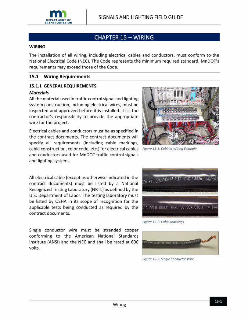
Inspection Traffic control signal and lighting system cables are usually inspected at the distributor by MnDOT. Documentation (cut sheet) showing project number, reel number(s), and MnDOT test number(s) will be included with each project shipment. If this documentation is not with the shipment, a sample of the cable must be sent to the MnDOT lab for testing along with material certification from the manufacturer. Testing at the MnDOT Materials Lab must be completed before cable is installed on the project.
After MnDOT approves cable at the distributor and a shipment is made to the project, a form is completed by the MnDOT lab inspector and sent to the MnDOT project engineer. The project engineer or MnDOT field Inspector should compare this document to the cut sheet provided by the contractor with the shipment of cable to ensure that the cable arriving on the job site has, in fact, been inspected and approved by MnDOT.
It is the inspector’s responsibility to check the wire and record the information on the Materials Inspection Form as the wire is furnished to the job site. A copy of the form is in the Appendix of this Field Guide.
Cables must be inspected and approved before installation and the contractor must be reminded of this at the pre-construction meeting. Any cables, not having the inspection documentation when furnished for installation, must be sampled and submitted to the MnDOT Materials Lab for testing. Once the wire is approved by the MnDOT Materials Lab, the contractor can install it.
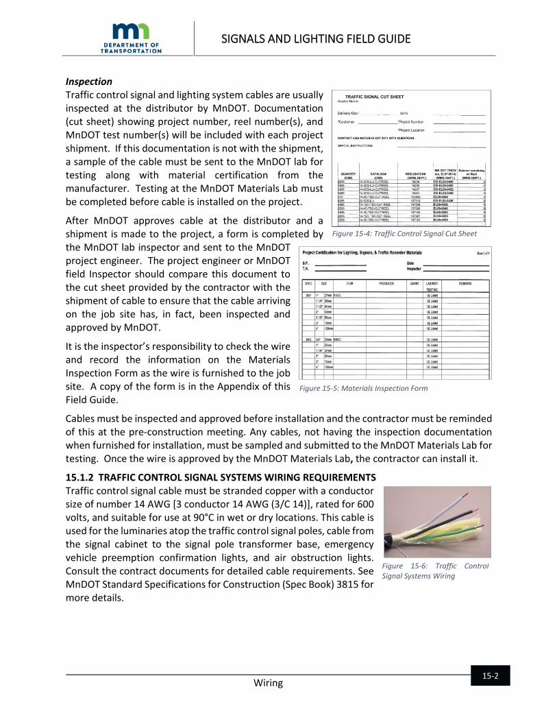
15.1.2 TRAFFIC CONTROL SIGNAL SYSTEMS WIRING REQUIREMENTS Traffic control signal cable must be stranded copper with a conductor size of number 14 AWG [3 conductor 14 AWG (3/C 14)], rated for 600 volts, and suitable for use at 90°C in wet or dry locations. This cable is used for the luminaries atop the traffic control signal poles, cable from the signal cabinet to the signal pole transformer base, emergency vehicle preemption confirmation lights, and air obstruction lights. Consult the contract documents for detailed cable requirements. See MnDOT Standard Specifications for Construction (Spec Book) 3815 for more details.
Figure 15-4: Traffic Control Signal Cut Sheet
Figure 15-5: Materials Inspection Form
Figure 15-6: Traffic Control Signal Systems Wiring

SIGNALS AND LIGHTING FIELD GUIDE
Wiring 15-3
15.1.3 LIGHTING SYSTEMS WIRING REQUIREMENTS Type 12-2 UF (with ground) cable must run from the light pole base to the luminaire on lighting system projects only.
Most MnDOT lighting projects require direct buried 4 conductor No. 4 AWG cable. Direct buried lighting cable must be in accordance with contract documents.
Within 15 days after the contract approval notice mailing date, the contractor must furnish evidence to the engineer, in writing, that orders have been placed for all direct buried lighting cable required for the project.
15.1.4 FIBER OPTIC COMMUNICATION CABLE Many projects are now calling for fiber optic cable to be used for traffic control signal interconnect. The benefits of using this type of back bone for communications are large bandwidth or the ability to pass large amounts of data up and down the corridor. This type of interconnect allows easy interconnection of field devices to a central office.
The two main types of fiber optic cable are multi-mode optical fiber and single mode fiber.
Multi-mode optical fiber, which is used for short haul (short distances) typically used in a building or on a campus. Patch cords will usually have an orange jacket.
Single mode fiber which is used for long haul distances like MnDOT traffic control signal interconnect and the Regional Transportation Management Center (RTMC) metro wide communications network (back bone). Patch cords will usually have a yellow jacket.
15.2 Wiring Installation
15.2.1 GENERAL REQUIREMENTS All electrical cables and conductors (except loop detector conductors) must be continuous (without splices) from the terminal appliances in the traffic control signal or lighting cabinet to the terminal appliances in the mast arm pole bases, pedestal bases and junction boxes.
Installing splices that are not authorized by the contract are not allowed. If it becomes necessary to splice a cable, the engineer must approve it in writing. Unless otherwise specified, splices must
Figure 15-7: Type 12-2 UF with Ground Cable
Figure 15-8: Lighting Cable
Figure 15-9: Multi-Mode Optical Fiber
Figure 15-10: Single-Mode Fiber
SIGNALS AND LIGHTING FIELD GUIDE
Wiring 15-4
be confined to handholes, control cabinets, junction boxes and the bases of poles. If underground cable splices are specified, they must be made using an approved epoxy splice kit listed on MnDOT’s Approved/Qualified Products List (APL) for traffic control signals or lighting. Additional details about splices are listed in contract documents. See Spec Book 2545.3G.4.b and 2565.3J for more details.
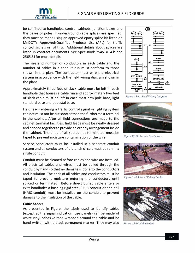
The size and number of conductors in each cable and the number of cables in a conduit run must conform to those shown in the plan. The contractor must wire the electrical system in accordance with the field wiring diagram shown in the plans.
Approximately three feet of slack cable must be left in each handhole that houses a cable run and approximately two feet of slack cable must be left in each mast arm pole base, light standard base and pedestal base.
Field leads entering a traffic control signal or lighting system cabinet must not be cut shorter than the furthermost terminal in the cabinet. After all field connections are made to the cabinet terminal facilities, field leads must be neatly dressed and banded together to provide an orderly arrangement inside the cabinet. The ends of all spares not terminated must be taped to prevent moisture contamination of the wire.
Service conductors must be installed in a separate conduit system and all conductors of a branch circuit must be run in a single conduit.
Conduit must be cleaned before cables and wire are installed. All electrical cables and wires must be pulled through the conduit by hand so that no damage is done to the conductors and insulation. The ends of all cables and conductors must be taped to prevent moisture entering the conductors until spliced or terminated. Before direct buried cable enters or exits handholes a bushing rigid steel (RSC) conduit or end bell (NMC conduit) must be installed on the conduit to prevent damage to the insulation of the cable.
Cable Labels As presented in Figure, the labels used to identify cables (except at the signal indication fuse panels) can be made of white vinyl adhesive tape wrapped around the cable and be hand written with a black permanent marker. They may also
Figure 15-11: Field Wiring Diagram
Figure 15-12: Service Conductors
Figure 15-13: Hand Pulling Cables
Figure 15-14: Cable Labels

SIGNALS AND LIGHTING FIELD GUIDE
Wiring 15-5
be machine printed labels suitable for use in wet locations with a minimum 1/10 inch overlap when installed on the cable assembly.
Cables must be identified as shown in the field wiring diagram in all handholes, junction boxes, traffic control signal pedestal bases, mast arm pole bases and the cabinet.
Above Ground Wiring All electrical cables and conductors installed above ground, except on overhead span wires, must be installed in conduit attached to wood poles, in metal poles, in cabinets or in other structures.
If electrical cables and conductors are to be installed overhead unsupported and spanned between wood poles or supports, sufficient slack must be furnished (generally five percent of the span length). Cables and conductors installed overhead in conjunction with a messenger wire (span wire) must be attached to the messenger wire using approved straps with a maximum spacing as required by the contract documents. Straps must be approved by the engineer prior to installation.
15.2.2 TRAFFIC CONTROL SIGNAL SYSTEMS WIRING INSTALLATION Loop lead-in cable (2/C 14) must be continuous from the splice in the handhole to traffic control signal cabinet.
Labels to identify the individual conductors terminated at the signal indication fuse panels must use either machine printed labels embossed plastic labels, vinyl adhesive preprinted labels, or sleeve type labels placed around each conductor.
As seen in Figure, in addition to labeling each cable within the cabinet, the contractor must label, in a similar manner, each conductor of each cable terminated on the fuse panel or terminal block (RED 2-1, YEL 2-1, GRN 2-1 and so on) indicating the signal indication and the signal head number. The label must be applied within three inches of the terminal point.
If a battery back system is required then the contractor must terminate wires on the inverter.
Figure 15-15: Above Ground Wiring
Figure 15-16: Sufficient Slack
Figure 15-17: Cable Labeling on the Fuse Panel
Figure 15-18: Wire Termination Battery Backup Inverter
SIGNALS AND LIGHTING FIELD GUIDE
Wiring 15-6
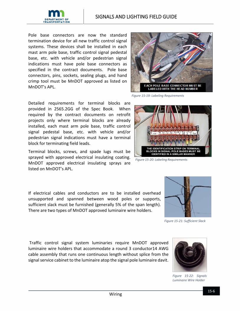
Pole base connectors are now the standard termination device for all new traffic control signal systems. These devices shall be installed in each mast arm pole base, traffic control signal pedestal base, etc. with vehicle and/or pedestrian signal indications must have pole base connectors as specified in the contract documents. Pole base connectors, pins, sockets, sealing plugs, and hand crimp tool must be MnDOT approved as listed on MnDOT’s APL.
Detailed requirements for terminal blocks are provided in 2565.2GG of the Spec Book. When required by the contract documents on retrofit projects only where terminal blocks are already installed, each mast arm pole base, traffic control signal pedestal base, etc. with vehicle and/or pedestrian signal indications must have a terminal block for terminating field leads.
Terminal blocks, screws, and spade lugs must be sprayed with approved electrical insulating coating. MnDOT approved electrical insulating sprays are listed on MnDOT’s APL.
If electrical cables and conductors are to be installed overhead unsupported and spanned between wood poles or supports, sufficient slack must be furnished (generally 5% of the span length). There are two types of MnDOT approved luminaire wire holders.
Traffic control signal system luminaries require MnDOT approved luminaire wire holders that accommodate a round 3 conductor14 AWG cable assembly that runs one continuous length without splice from the signal service cabinet to the luminaire atop the signal pole luminaire davit.
Figure 15-19: Labeling Requirements
Figure 15-22: Signals Luminaire Wire Holder
Figure 15-21: Sufficient Slack
Figure 15-20: Labeling Requirements
SIGNALS AND LIGHTING FIELD GUIDE
Wiring 15-7
15.2.3 LIGHTING SYSTEMS WIRING INSTALLATION Underground Wiring Direct Buried Lighting Cable Underground direct buried lighting cable must be installed in accordance with MnDOT 2545.3 G.
The lighting cable must be installed at the same distance behind the bituminous shoulder or back of curb as the light foundations.
When an obstruction has been encountered in the path of the direct buried lighting cable, re-route the direct buried lighting cable around the obstruction away from the roadway. All changes to cable location must be shown in the as-builts.
Direct buried lighting cable must be installed in rigid PVC or HDPE conduit under paved surfaces per 2545.3G.2.
Use a vibratory plow with a plow blade chute to reduce stresses on the cable during installation.
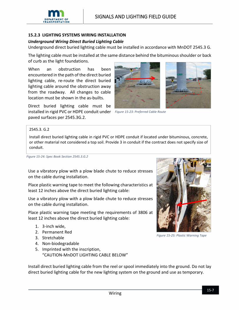
Place plastic warning tape to meet the following characteristics at least 12 inches above the direct buried lighting cable:
Use a vibratory plow with a plow blade chute to reduce stresses on the cable during installation.
Place plastic warning tape meeting the requirements of 3806 at least 12 inches above the direct buried lighting cable:
1. 3-inch wide, 2. Permanent Red 3. Stretchable 4. Non-biodegradable 5. Imprinted with the inscription,
“CAUTION-MnDOT LIGHTING CABLE BELOW” Install direct buried lighting cable from the reel or spool immediately into the ground. Do not lay direct buried lighting cable for the new lighting system on the ground and use as temporary.
Figure 15-23: Preferred Cable Route
2545.3. G.2
Install direct buried lighting cable in rigid PVC or HDPE conduit if located under bituminous, concrete, or other material not considered a top soil. Provide 3 in conduit if the contract does not specify size of conduit.
Figure 15-24: Spec Book Section 2545.3.G.2
Figure 15-25: Plastic Warning Tape
SIGNALS AND LIGHTING FIELD GUIDE
Wiring 15-8
Provide two feet of slack cable in an “S” pattern (within the width of the foundation) before cable enters the light foundation.
On a project where guardrail is also being installed, locate and/or install the guardrail before placing the lighting cable in order to help reduce or eliminate cable hits.
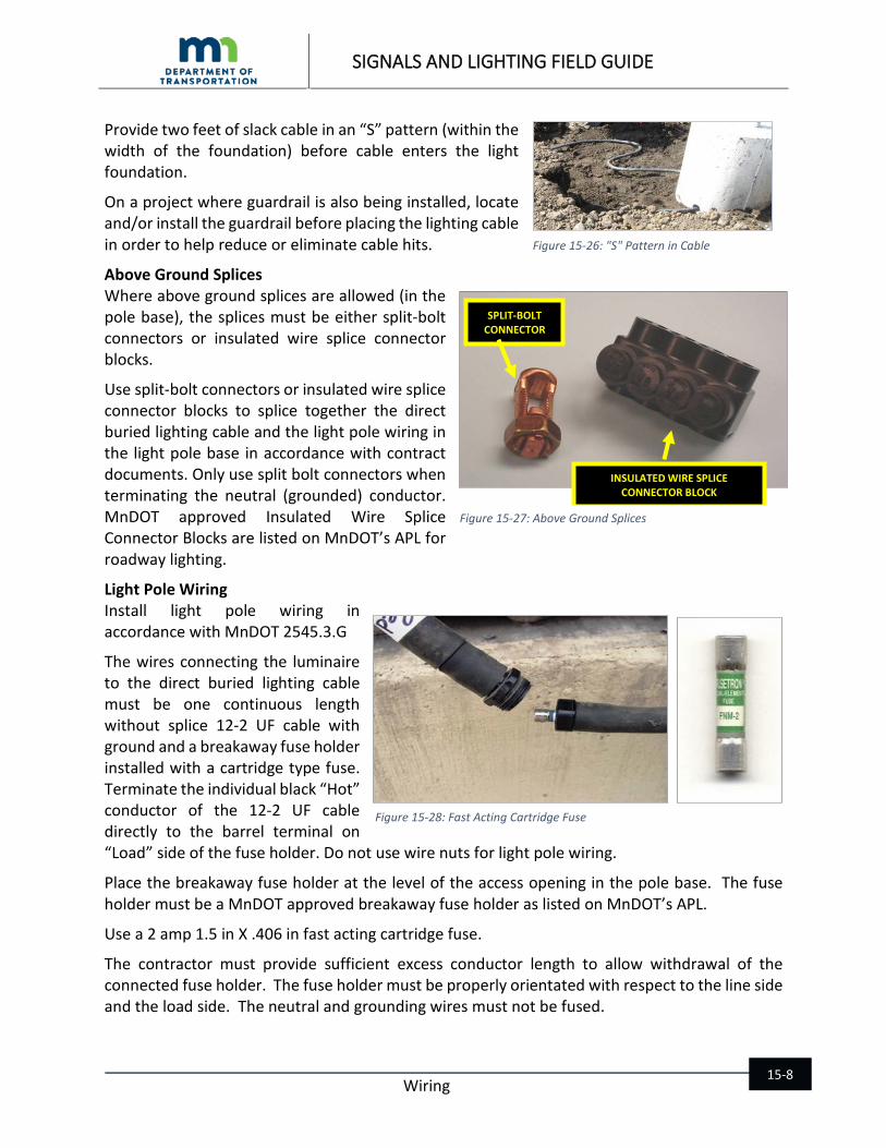
Above Ground Splices Where above ground splices are allowed (in the pole base), the splices must be either split-bolt connectors or insulated wire splice connector blocks.
Use split-bolt connectors or insulated wire splice connector blocks to splice together the direct buried lighting cable and the light pole wiring in the light pole base in accordance with contract documents. Only use split bolt connectors when terminating the neutral (grounded) conductor. MnDOT approved Insulated Wire Splice Connector Blocks are listed on MnDOT’s APL for roadway lighting.
Light Pole Wiring Install light pole wiring in accordance with MnDOT 2545.3.G
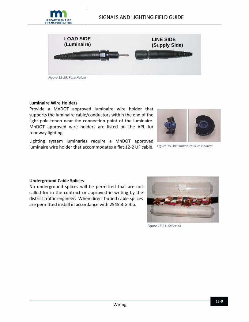
The wires connecting the luminaire to the direct buried lighting cable must be one continuous length without splice 12-2 UF cable with ground and a breakaway fuse holder installed with a cartridge type fuse. Terminate the individual black “Hot” conductor of the 12-2 UF cable directly to the barrel terminal on “Load” side of the fuse holder. Do not use wire nuts for light pole wiring.
Place the breakaway fuse holder at the level of the access opening in the pole base. The fuse holder must be a MnDOT approved breakaway fuse holder as listed on MnDOT’s APL.
Use a 2 amp 1.5 in X .406 in fast acting cartridge fuse.
The contractor must provide sufficient excess conductor length to allow withdrawal of the connected fuse holder. The fuse holder must be properly orientated with respect to the line side and the load side. The neutral and grounding wires must not be fused.
Figure 15-26: "S" Pattern in Cable
SPLIT-BOLT CONNECTOR
INSULATED WIRE SPLICE CONNECTOR BLOCK
Figure 15-27: Above Ground Splices
Figure 15-28: Fast Acting Cartridge Fuse
SIGNALS AND LIGHTING FIELD GUIDE
Wiring 15-9
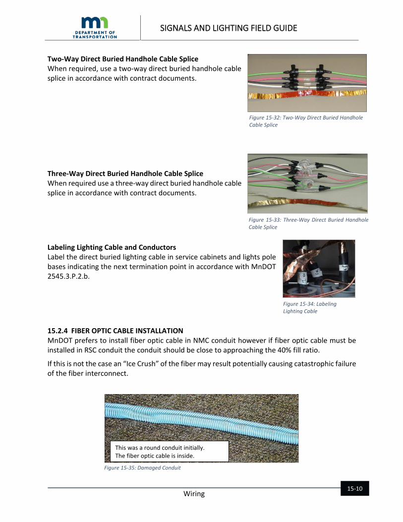
Luminaire Wire Holders Provide a MnDOT approved luminaire wire holder that supports the luminaire cable/conductors within the end of the light pole tenon near the connection point of the luminaire. MnDOT approved wire holders are listed on the APL for roadway lighting.
Lighting system luminaries require a MnDOT approved luminaire wire holder that accommodates a flat 12-2 UF cable.
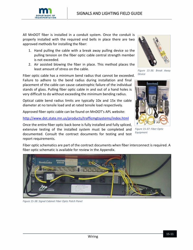
Underground Cable Splices No underground splices will be permitted that are not called for in the contract or approved in writing by the district traffic engineer. When direct buried cable splices are permitted install in accordance with 2545.3.G.4.b.
LOAD SIDE (Luminaire)
LINE SIDE (Supply Side)
Figure 15-29: Fuse Holder
Figure 15-30: Luminaire Wire Holders
Figure 15-31: Splice Kit
SIGNALS AND LIGHTING FIELD GUIDE
Wiring 15-10
Two-Way Direct Buried Handhole Cable Splice When required, use a two-way direct buried handhole cable splice in accordance with contract documents.
Three-Way Direct Buried Handhole Cable Splice When required use a three-way direct buried handhole cable splice in accordance with contract documents.
Labeling Lighting Cable and Conductors Label the direct buried lighting cable in service cabinets and lights pole bases indicating the next termination point in accordance with MnDOT 2545.3.P.2.b.
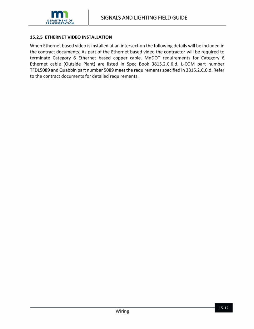
15.2.4 FIBER OPTIC CABLE INSTALLATION MnDOT prefers to install fiber optic cable in NMC conduit however if fiber optic cable must be installed in RSC conduit the conduit should be close to approaching the 40% fill ratio.
If this is not the case an “Ice Crush” of the fiber may result potentially causing catastrophic failure of the fiber interconnect.
This was a round conduit initially. The fiber optic cable is inside.
Figure 15-35: Damaged Conduit
Figure 15-34: Labeling Lighting Cable
Figure 15-33: Three-Way Direct Buried Handhole Cable Splice
Figure 15-32: Two-Way Direct Buried Handhole Cable Splice
SIGNALS AND LIGHTING FIELD GUIDE
Wiring 15-11
All MnDOT fiber is installed in a conduit system. Once the conduit is properly installed with the required end bells in place there are two approved methods for installing the fiber:
1. Hand pulling the cable with a break away pulling device so the pulling tension on the fiber optic cable central strength member is not exceeded.
2. Air assisted blowing the fiber in place. This method places the least amount of stress on the cable.
Fiber optic cable has a minimum bend radius that cannot be exceeded. Failure to adhere to the bend radius during installation and final placement of the cable can cause catastrophic failure of the individual stands of glass. Pulling fiber optic cable in and out of a hand holes is very difficult to do without exceeding the minimum bending radius.
Optical cable bend radius limits are typically 10x and 15x the cable diameter at no tensile load and at rated tensile load respectively.
Approved fiber optic cable can be found on MnDOT’s APL website:
http://www.dot.state.mn.us/products/trafficmgtsystems/index.html
Once the entire fiber optic back bone is fully installed and fully spliced, extensive testing of the installed system must be completed and documented. Consult the contract documents for testing and test report requirements.
Fiber optic schematics are part of the contract documents when fiber interconnect is required. A fiber optic schematic is available for review in the Appendix.
Figure 15-38: Signal Cabinet Fiber Optic Patch Panel
Figure 14-36: Break Away Device
Figure 15-36: Break Away Device
Figure 15-37: Fiber Optic Equipment
SIGNALS AND LIGHTING FIELD GUIDE
Wiring 15-12
15.2.5 ETHERNET VIDEO INSTALLATION
When Ethernet based video is installed at an intersection the following details will be included in the contract documents. As part of the Ethernet based video the contractor will be required to terminate Category 6 Ethernet based copper cable. MnDOT requirements for Category 6 Ethernet cable (Outside Plant) are listed in Spec Book 3815.2.C.6.d. L-COM part number TFDL5089 and Quabbin part number 5089 meet the requirements specified in 3815.2.C.6.d. Refer to the contract documents for detailed requirements.

SIGNALS AND LIGHTING FIELD GUIDE
Wiring 15-13
Figure 15-39: Camera Detail Page 1

SIGNALS AND LIGHTING FIELD GUIDE
Wiring 15-14
Figure 15-40: IP Camera Wiring Detail Page 2
SIGNALS AND LIGHTING FIELD GUIDE
Wiring 15-15
15.3 Chapter 15 Resources • MnDOT Approved Products List (APL) • National Electrical Code (NEC). • MnDOT Standard Specifications for Construction 3815, 2565.3.J, 2565.2.GG, 3815.2.C.6.d,
2545.3.G, 2545.3.P.2.b.

SIGNALS AND LIGHTING FIELD GUIDE
Wiring 15-16
This Page Intentionally Left Blank