Chapter 15 Unilateral and Bilateral Rehabilitation of the...
42
Chapter 15 Unilateral and Bilateral Rehabilitation of the Upper Limb Following Stroke via an Exoskeleton Jacob Rosen, Dejan Milutinovi´ c, Levi M. Miller, Matt Simkins, Hyunchul Kim, and Zhi Li Abstract Recent studies reported positive effects of bilateral arm training on stroke rehabilitations. The development of novel robotic-based therapeutic interventions aims at recovery of the motor control system of the upper limb, in addition to the increase of the understanding of neurological mechanisms underlying the recovery of function post stroke. A dual-arm upper limb exoskeleton EXO-UL7 that is kinematically compatible with the human arm is developed to assist unilateral and bilateral training after stroke. Control algorithms are designed and implemented to improve the synergy of the human arm and the upper limb exoskeleton. Clinical studies on the robot-assisted bilateral rehabilitations show that both the unilateral and bilateral training have a positive effect on the recovery of the paretic arm. Bilateral training outperforms unilateral training by a significant improvement of motion range and movement velocities. Keywords Unilateral/bilateral stroke rehabilitation • Upper limb exoskeleton • Human arm • Kinematics • Dynamics J. Rosen () • D. Milutinovi´ c • M. Simkins • Z. Li Department of Computer Engineering, University of California, Santa Cruz, CA 95064, USA e-mail: [email protected]; [email protected]; [email protected]; [email protected] L.M. Miller Carbon Design Group, Seattle, WA, USA e-mail: [email protected] H. Kim Apple Inc., Cupertino, CA, USA e-mail: [email protected] P. Artemiadis (ed.), Neuro-Robotics: From Brain Machine Interfaces to Rehabilitation Robotics, Trends in Augmentation of Human Performance 2, DOI 10.1007/978-94-017-8932-5__15, © Springer Science+BusinessMedia Dordrecht 2014 405
Transcript of Chapter 15 Unilateral and Bilateral Rehabilitation of the...
Chapter 15Unilateral and Bilateral Rehabilitationof the Upper Limb Following Strokevia an Exoskeleton
Jacob Rosen, Dejan Milutinovic, Levi M. Miller, Matt Simkins,Hyunchul Kim, and Zhi Li
Abstract Recent studies reported positive effects of bilateral arm training on strokerehabilitations. The development of novel robotic-based therapeutic interventionsaims at recovery of the motor control system of the upper limb, in addition to theincrease of the understanding of neurological mechanisms underlying the recoveryof function post stroke. A dual-arm upper limb exoskeleton EXO-UL7 that iskinematically compatible with the human arm is developed to assist unilateral andbilateral training after stroke. Control algorithms are designed and implemented toimprove the synergy of the human arm and the upper limb exoskeleton. Clinicalstudies on the robot-assisted bilateral rehabilitations show that both the unilateraland bilateral training have a positive effect on the recovery of the paretic arm.Bilateral training outperforms unilateral training by a significant improvement ofmotion range and movement velocities.
Keywords Unilateral/bilateral stroke rehabilitation • Upper limb exoskeleton •Human arm • Kinematics • Dynamics
J. Rosen (�) • D. Milutinovic • M. Simkins • Z. LiDepartment of Computer Engineering, University of California, Santa Cruz, CA 95064, USAe-mail: [email protected]; [email protected]; [email protected]; [email protected]
L.M. MillerCarbon Design Group, Seattle, WA, USAe-mail: [email protected]
H. KimApple Inc., Cupertino, CA, USAe-mail: [email protected]
P. Artemiadis (ed.), Neuro-Robotics: From Brain Machine Interfacesto Rehabilitation Robotics, Trends in Augmentation of Human Performance 2,DOI 10.1007/978-94-017-8932-5__15, © Springer Science+Business Media Dordrecht 2014
405

406 J. Rosen et al.
15.1 Introduction
Stroke is a leading cause of long-term neurological disability and the top reason forseeking rehabilitative services in the U.S. Challenges in rehabilitation after stroke,especially in the chronic phase are two-fold: the first is the development of systemsfor intense delivery of targeted rehabilitative interventions based on neural plasticitythat will facilitate recovery and the second is to understand neural reorganizationthat facilitates the recovery of function. Whereas in the acute phase post stroke,medical management focuses on containing and minimizing the extent of the injury,in the chronic phase post stroke, neural plasticity induced by learning/trainingis the fundamental mechanism for recovery. The development of novel roboticbased therapeutic interventions aims at facilitating neural plasticity and inducingsustainable recovery of the motor control system of the upper limb. In addition,studies on the synergy of the human are and wearable robotic system (e.g., an upperlimb exoskeleton) improve the understanding of neurological mechanisms whichaim to maximize the recovery of function post stroke.
15.1.1 Bilateral Robotic System and Treatment
Research studies suggest that manual bilateral movements in which both armsand hands move simultaneously in a mirror image fashion or work simultaneouslywhile performing a bilateral task have profound effects on the reorganization of theneural system due to inherent brain plasticity. Using such a therapeutic approach forstroke patients is based on the understanding that both brain hemispheres (damagedand undamaged) are going through a natural recovery process, as well as neuralreorganization following a learning-based therapy. In spite of significant scientificevidence, translating a mirror image bilateral therapeutic approach into an intense(high dosage) physical rehabilitation treatment regime has been difficult. A therapistadministering this regime is challenged to simultaneously control the 16 degrees offreedom (DOF) of both arms (14 DOF) and hands (2 DOF limited to 3-point chucktype grasping).
When considering bilateral symmetric movement training as an option fortherapy, there are two aspects to its efficacy. The first aspect relates to neuroscience.Based on experiments relating to bilateral symmetric manual coordination usingtrans-cranial magnetic stimulation and kinematic modeling, symmetric movementmight reduce inhibitions between the left and right hemispheres [1, 2]. In otherwords, bilateral symmetric movements have been found to increase cross-talk in thecorpus callosum. In that vein, multiple studies have demonstrated the effectivenessof mirror therapy. Using mirror therapy, stroke survivors were able to improvefunction based on the optical illusions of their paretic arm moving normally [3, 4].Based on such research, it has been proposed that symmetric movement trainingmight exploit such coupling thereby allowing for an increased use of undamaged
15 Unilateral and Bilateral Rehabilitation of the Upper Limb Following. . . 407
ipsilateral projections [5]. In this way, symmetric movement training might improvethe recovery process after a CVA. With respect to clinical outcomes, the results aresomewhat mixed. It is admittedly difficult to detect improvement. For individualswho have chronic motor impairment, improvement after therapy is often subtle.Standard care, unilateral and bilateral movement training have all been shown toresult in some improvement. However, distinguishing between training modalitiesis difficult and the differences are small. To that end, there is virtually no data(such as brain imaging) relating to neurological activity and bilateral therapy. Forthese reasons, it remains uncertain if bilateral symmetric therapy is truly betterthan unilateral therapy in the sense that there is more or less cross-talk betweenthe hemispheres. More to the point, there is no conclusive evidence that bilateralsymmetric movement training has a neurological basis.
Beyond neurological considerations, there are factors that distinguish the efficacyof bilateral and unilateral movement training. Bilateral movement training wasshown to have better results than unilateral movement training in terms of therange of motion (ROM). One explanation for this difference is that the pareticarm was provided robotic assistance, while in the unilateral case, no assistance wasprovided. Subjects also reported that they preferred assistance [6]. While it is truethat a robot can provide assistance for unilateral movement training, the controlalgorithms and game designs become much more constrained. During movementtraining, providing assistance that moves the arm through large angles might makethe therapy feel unpredictable and might raise safety concerns. However, when theparetic arm is made to move symmetrically with the less affected arm, the subject isin control, and the game play is more predictable and the assistance is more natural.Therefore, bilateral training provides a flexible control paradigm for unstructuredassistance.
There are two approaches for bilateral training. One involves full assistance [7]and the other requires partial assistance [6]. For full assistance, the paretic arm isforced into symmetric motion. Using this approach, the subjects may focus entirelyon their less affected limb in order to play therapy games or to complete tasks.The subjects might use a minimum of effort to move their paretic arm, and whatmovements they do make will have little to no effect on the game play or taskcompletion. Bilateral symmetric movement training with partial assistance allowsthe robot to provide some help for the paretic arm. However, the subjects cannotquite play the game or complete the task with their paretic arm unless they providesome voluntary effort. Subjects also perceived better outcomes for full assistancethan partial assistance [6].
Bilateral symmetric movement training does have the potential to aggravatespasticity [6]. The cause for this relates to the speed of motion. It is known thatrapid flexion and extension of spastic joints can intensify existing spasticity. Thisin turn can result in pain, weakness, and reduced coordination. When subjectsperform symmetric movements, their less affected arm might move too rapidly.In turn, as the robot attempts to maintain symmetry, the paretic arm might movetoo quickly thus aggravating spasticity. The largest effects were evident in the hand.Therefore, bilateral symmetric movement is recommended for individuals who have

408 J. Rosen et al.
mild spasticity. If robotic training is used with assistance, be it bilateral or unilateral,care is needed not to move the paretic arm too fast.
15.1.2 Robot-Assisted Stroke Rehabilitation
Recently research results have demonstrated that robotic devices can deliver effec-tive rehabilitation therapies to patients suffering from the chronic neuromusculardisorders [8–10]. MIT-MANUS is one of the successful rehabilitation robotswhich adopted back-drivable hardware and impedance control as a robot controlsystem [11]. ARMin is a 7-DOF upper limb exoskeleton developed in ETH Zurichand the University of Zurich. This robot provides visual, acoustic and hapticinterfaces together with cooperative control strategies to facilitate the patient’s activeparticipation in the game. The lengths of the upper arm, lower arm, hand and theheight of the device are adjustable to accommodate patients of different sizes. Therehabilitation site and robotic system are wheelchair accessible. Pneu-WREX isa 6-DOF exoskeleton robot developed in UC Irvine. This robotic system adoptedpneumatic actuators [12]. Although the pneumatic actuator is harder to controldue to its non-linear characteristics, it produces relatively large forces with a lowon-board weigh [13]. The robot interacts with the virtual-reality game T-WREXbased on a Java Therapy 2.0 software system. Arizona State University researchersdeveloped a robotic arm, RUPERT (Robotic Upper Extremity Repetitive Therapy)targeting cost-effective and light-weight stroke patient rehabilitation [14, 15]. Thedevice provides the patient with assistive force to facilitate fluid and naturalarm movements essential for the activities of daily living. The controller for thepneumatic muscles can be programmed for each user to improve their arm andhand flexibility, as well as strength by providing a repetitive exercise pattern.In our previous work [16], the seven-DOF exoskeleton robot UL-EXO7 [8, 17, 18]was exploited as a core mechanical system for the long-term clinical trial ofthe bilateral and unilateral rehabilitation program. The controllers equipped inUL-EXO7 provided the assistive force to help patients make the natural armposture based on the work in [19,20]. For the objective and fine-scale rehabilitationassessment, a new assessment metric, an efficiency index, was introduced to tell thetherapist how close the patient’s arm movements are to the normal subject’s armmovements.
15.1.3 Objective and Paper Structure
This chapter describes the EXO-UL7 – an upper limb exoskeleton system andits clinical applications to bilateral stroke rehabilitation. Section 15.2 reviews thekinematic design of the EXO-UL7 with considerations in its compatibility withthe kinematics of the human arm. Based on the kinematic modeling of the human
15 Unilateral and Bilateral Rehabilitation of the Upper Limb Following. . . 409
arm, the forward and inverse kinematics are derived. The control architectures areaddressed, including the control algorithms for admittance control, gravity com-pensation, inter-arm teleoperation and redundancy resolution. Clinical studies onrobot-assisted bilateral rehabilitations are presented in Sect. 15.3, with a comparisonof the outcomes of unilateral and bilateral training.
15.2 An Upper Limb Exoskeleton: EXO-UL7
15.2.1 System Overview
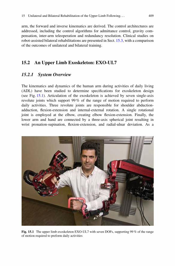
The kinematics and dynamics of the human arm during activities of daily living(ADL) have been studied to determine specifications for exoskeleton design(see Fig. 15.1). Articulation of the exoskeleton is achieved by seven single-axisrevolute joints which support 99 % of the range of motion required to performdaily activities. Three revolute joints are responsible for shoulder abduction-adduction, flexion-extension and internal-external rotation. A single rotationaljoint is employed at the elbow, creating elbow flexion-extension. Finally, thelower arm and hand are connected by a three-axis spherical joint resulting inwrist pronation-supination, flexion-extension, and radial-ulnar deviation. As a
Fig. 15.1 The upper limb exoskeleton EXO-UL7 with seven DOFs, supporting 99 % of the rangeof motion required to preform daily activities
410 J. Rosen et al.
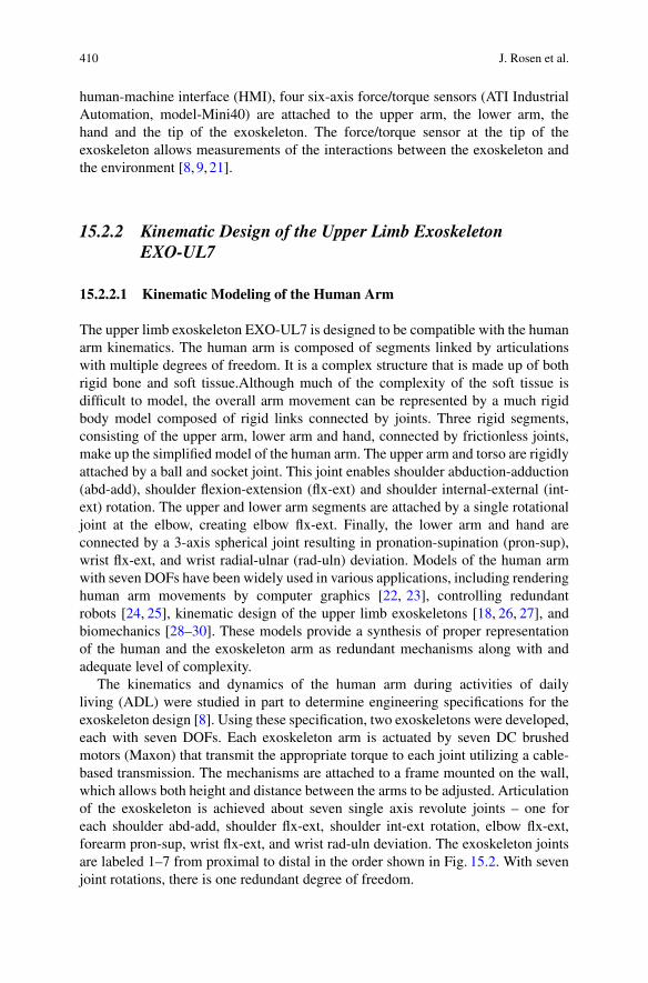
human-machine interface (HMI), four six-axis force/torque sensors (ATI IndustrialAutomation, model-Mini40) are attached to the upper arm, the lower arm, thehand and the tip of the exoskeleton. The force/torque sensor at the tip of theexoskeleton allows measurements of the interactions between the exoskeleton andthe environment [8, 9, 21].
15.2.2 Kinematic Design of the Upper Limb ExoskeletonEXO-UL7
15.2.2.1 Kinematic Modeling of the Human Arm
The upper limb exoskeleton EXO-UL7 is designed to be compatible with the humanarm kinematics. The human arm is composed of segments linked by articulationswith multiple degrees of freedom. It is a complex structure that is made up of bothrigid bone and soft tissue.Although much of the complexity of the soft tissue isdifficult to model, the overall arm movement can be represented by a much rigidbody model composed of rigid links connected by joints. Three rigid segments,consisting of the upper arm, lower arm and hand, connected by frictionless joints,make up the simplified model of the human arm. The upper arm and torso are rigidlyattached by a ball and socket joint. This joint enables shoulder abduction-adduction(abd-add), shoulder flexion-extension (flx-ext) and shoulder internal-external (int-ext) rotation. The upper and lower arm segments are attached by a single rotationaljoint at the elbow, creating elbow flx-ext. Finally, the lower arm and hand areconnected by a 3-axis spherical joint resulting in pronation-supination (pron-sup),wrist flx-ext, and wrist radial-ulnar (rad-uln) deviation. Models of the human armwith seven DOFs have been widely used in various applications, including renderinghuman arm movements by computer graphics [22, 23], controlling redundantrobots [24, 25], kinematic design of the upper limb exoskeletons [18, 26, 27], andbiomechanics [28–30]. These models provide a synthesis of proper representationof the human and the exoskeleton arm as redundant mechanisms along with andadequate level of complexity.
The kinematics and dynamics of the human arm during activities of dailyliving (ADL) were studied in part to determine engineering specifications for theexoskeleton design [8]. Using these specification, two exoskeletons were developed,each with seven DOFs. Each exoskeleton arm is actuated by seven DC brushedmotors (Maxon) that transmit the appropriate torque to each joint utilizing a cable-based transmission. The mechanisms are attached to a frame mounted on the wall,which allows both height and distance between the arms to be adjusted. Articulationof the exoskeleton is achieved about seven single axis revolute joints – one foreach shoulder abd-add, shoulder flx-ext, shoulder int-ext rotation, elbow flx-ext,forearm pron-sup, wrist flx-ext, and wrist rad-uln deviation. The exoskeleton jointsare labeled 1–7 from proximal to distal in the order shown in Fig. 15.2. With sevenjoint rotations, there is one redundant degree of freedom.

15 Unilateral and Bilateral Rehabilitation of the Upper Limb Following. . . 411
Fig. 15.2 Exoskeleton axes assignment relative to the human arm. Positive rotations about eachjoint produce the following motions: (1) combined flx/adb, (2) combined flx/add, (3) int rotation,(4) elbow flx, (5) forearm pron, (6) wrist ext, and (7) wrist rad dev
The fundamental principle in designing the exoskeleton joints is to align therotational axis of the exoskeleton with the anatomical rotations axes. If more thanone axis is at a particular anatomical joint (e.g. shoulder and wrist), the exoskeletonjoints emulate the anatomical joint interaction at the center of the anatomical joint.Consistent with other work, the glenohumeral (G-H) joint is modeled as a sphericaljoint composed of three intersection axes [31]. The elbow is modeled by a single axisorthogonal to the third shoulder axis, with a joint stop to prevent hyperextension.Exoskeleton pron-sup takes place between the elbow and the wrist as it does. Finally,two intersecting orthogonal axes represent the wrist. The ranges of motion of theexoskeleton joints support 99 % of the ranges of motion required to perform dailyactivities [8].
Representing the ball and socket joint of the shoulder as three intersecting joinsintroduces of singularities that are not present in the human arm model. A significantconsideration in the exoskeleton design is the placement of singularities [24]. Thesingularity is a device configuration in which a DOF is lost or compromised as aresult of the alignment of two rotational axes. In the development of a three DOF

412 J. Rosen et al.
Fig. 15.3 Two singularities exist in the exoskeleton device, one when joints 1 and 3 align and theother when joints 3 and 5 align. (a) The orientation of joint 1 places the singularity at the shoulderin an anthropomorphically difficult place to reach. (b) Joints 1 and 3 align with simultaneousextension and abduction of the upper arm by 47:5ı and 53:6 ı. (c) Similarly, the same singularitycan be reached through flexion and adduction by 132:5ı and 53:6ı. (d) Alignment of joints 3 and5 naturally occurs only in full elbow extension
spherical joint, the existence or nonexistence of singularities will depend entirelyon the desired reachable workspace. Spherical workspace equal to or larger thana hemisphere will always contain singular positions. The challenge is to placethe singularity in an unreachable, or near-unreachable location, such as the edgeof the workspace. For the exoskeleton arm, singularities occur when joints 1 and3 or joints 3 and 5 align. To minimize the frequency of this occurrence, theaxis of joint 1 is positioned such that singularities with joint 3 take place onlyat locations that are anthropometrically hard to reach. For the placement shownin Fig. 15.3a, the singularity can be reached through simultaneous extension andabduction of the upper arm by 47:5ı and 53:6ı, respectively (see Fig. 15.3b).Similarly, the same singularity can be reached through flexion and adduction by132:5ı and 53:6ı, respectively (see Fig. 15.3c). The singularity between joints 3
15 Unilateral and Bilateral Rehabilitation of the Upper Limb Following. . . 413
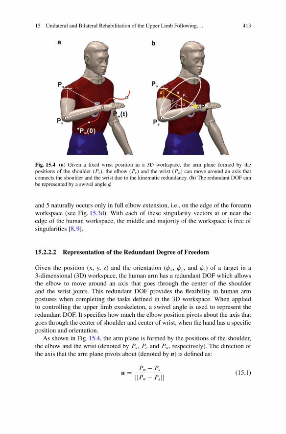
Fig. 15.4 (a) Given a fixed wrist position in a 3D workspace, the arm plane formed by thepositions of the shoulder (Ps), the elbow (Pe) and the wrist (Pw) can move around an axis thatconnects the shoulder and the wrist due to the kinematic redundancy. (b) The redundant DOF canbe represented by a swivel angle �
and 5 naturally occurs only in full elbow extension, i.e., on the edge of the forearmworkspace (see Fig. 15.3d). With each of these singularity vectors at or near theedge of the human workspace, the middle and majority of the workspace is free ofsingularities [8, 9].
15.2.2.2 Representation of the Redundant Degree of Freedom
Given the position (x, y, z) and the orientation (�x , �y , and �z) of a target in a3-dimensional (3D) workspace, the human arm has a redundant DOF which allowsthe elbow to move around an axis that goes through the center of the shoulderand the wrist joints. This redundant DOF provides the flexibility in human armpostures when completing the tasks defined in the 3D workspace. When appliedto controlling the upper limb exoskeleton, a swivel angle is used to represent theredundant DOF. It specifies how much the elbow position pivots about the axis thatgoes through the center of shoulder and center of wrist, when the hand has a specificposition and orientation.
As shown in Fig. 15.4, the arm plane is formed by the positions of the shoulder,the elbow and the wrist (denoted by Ps , Pe and Pw, respectively). The direction ofthe axis that the arm plane pivots about (denoted by n) is defined as:
n D Pw � Ps
jjPw � Psjj (15.1)
414 J. Rosen et al.
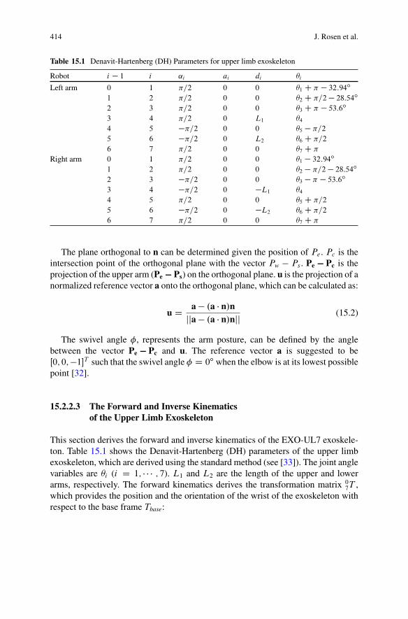
Table 15.1 Denavit-Hartenberg (DH) Parameters for upper limb exoskeleton
Robot i � 1 i ˛i ai di �i
Left arm 0 1 �=2 0 0 �1 C � � 32:94ı
1 2 �=2 0 0 �2 C �=2 � 28:54ı
2 3 �=2 0 0 �3 C � � 53:6ı
3 4 �=2 0 L1 �4
4 5 ��=2 0 0 �5 � �=2
5 6 ��=2 0 L2 �6 C �=2
6 7 �=2 0 0 �7 C �
Right arm 0 1 �=2 0 0 �1 � 32:94ı
1 2 �=2 0 0 �2 � �=2 � 28:54ı
2 3 ��=2 0 0 �3 � � � 53:6ı
3 4 ��=2 0 �L1 �4
4 5 �=2 0 0 �5 C �=2
5 6 ��=2 0 �L2 �6 C �=2
6 7 �=2 0 0 �7 C �
The plane orthogonal to n can be determined given the position of Pe . Pc is theintersection point of the orthogonal plane with the vector Pw � Ps . Pe � Pc is theprojection of the upper arm (Pe � Ps) on the orthogonal plane. u is the projection of anormalized reference vector a onto the orthogonal plane, which can be calculated as:
u D a � .a � n/njja � .a � n/njj (15.2)
The swivel angle �, represents the arm posture, can be defined by the anglebetween the vector Pe � Pc and u. The reference vector a is suggested to beŒ0; 0; �1�T such that the swivel angle � D 0ı when the elbow is at its lowest possiblepoint [32].
15.2.2.3 The Forward and Inverse Kinematicsof the Upper Limb Exoskeleton
This section derives the forward and inverse kinematics of the EXO-UL7 exoskele-ton. Table 15.1 shows the Denavit-Hartenberg (DH) parameters of the upper limbexoskeleton, which are derived using the standard method (see [33]). The joint anglevariables are �i (i D 1; � � � ; 7). L1 and L2 are the length of the upper and lowerarms, respectively. The forward kinematics derives the transformation matrix 0
7T ,which provides the position and the orientation of the wrist of the exoskeleton withrespect to the base frame Tbase:

15 Unilateral and Bilateral Rehabilitation of the Upper Limb Following. . . 415
Table 15.2 Base rotation ofthe upper limb exoskeleton
�X (ı) �Y (ı) �Z (ı)
Left arm 132.5 45 90Right arm 132.5 �45 90
base7 T D Tbase � 0
1T � 12T � 2
3T � 34T � 4
5T � 56T � 6
7T
D
2664
r11 r12 r13 Pwx
r21 r22 r23 Pwy
r31 r32 r33 Pwz
0 0 0 1
3775 (15.3)
In order to move the singularity out of the range of the daily movements of thehuman arm, the bases of the two robotic arms of the upper limb exoskeleton arerotated according to Table 15.2. Note that �X , �Y and �Z represent the rotation aboutthe X, Y and Z-axis, respectively. The transformation matrix for the base rotation isdescribed in Eq. (15.4).
Tbase D Rotx.�X /Rotz.�Y /Rotz.�Z/ (15.4)
With the specification of the transformation matrix 07T , the inverse kinematics
of the exoskeleton can be derived for the left and the right arm, respectively. Theredundant DOF of the human arm can be constrained by specifying the elbowposition (Pe D ŒP ex; P ey; P ez�
T ).Based on the shoulder position Ps , elbow position Pe , and wrist position Pw, �4
can be derived as:
W D jjPw � Psjj (15.5)
c4 D L21 C L2
2 � W 2
2L1L2
(15.6)
s4 Dq
1 � c24 (15.7)
�4 D � � Atan2.s4; c4/ (15.8)
The transformation matrix 34T and its inverse 3
4T �1 can be found based on �4.The transformation matrix without the base rotation, denoted base
7 T , can befound by:
07T D T �1
0 �base7 T D
2664
r 011 r 0
12 r 013
07Pwx
r 021 r 0
22 r 023
07Pwy
r 031 r 0
32 r 033
07Pwz
0 0 0 1
3775 (15.9)
Thus, the wrist position with respect to the rotated base is 07Pw D Œ07Pwx , 0
7Pwy ,07Pwz�
T .

416 J. Rosen et al.
Similarly, the elbow position with respect to the rotated base, denoted by 07Pe D
Œ07Pex , 07Pey , 0
7Pez�T , is:
2664
07Pex07Pey07Pez
1
3775 D T �1
0 �
2664
base7 Pexbase7 Peybase7 Pez
1
3775 (15.10)
Note that 07Pe D 0
4Pe and
04T D 0
1T �12 T �23 T �34 T D
2664
04Pex
04R 0
4Pey04Pez
0 0 0 1
3775 D
2664
L1c1s204R L1c2
L1s1s2
0 0 0 1
3775 (15.11)
For the both arms,
c2 D04Pey
L1
(15.12)
For the left arm,
s2 Dp
.1 � c22/ (15.13)
For the right arm,
s2 D �p
.1 � c22/ (15.14)
Thus, �2 can be resolved as:
�2 D Atan2.s2; c2/ � .�=2 � 28:54ı/ (15.15)
To resolve �1, for the both arms,
c1 D04Pex
L1s2
(15.16)
s1 D04Pez
L1s2
(15.17)
Thus, for the left arm,
�1 D Atan2.s1; c1/ � .� � 32:94ı/ (15.18)

15 Unilateral and Bilateral Rehabilitation of the Upper Limb Following. . . 417
For the right arm,
�1 D Atan2.s1; c1/ C 32:94ı (15.19)
The transformation matrices 01T and 1
2T and their inverses 01T �1 and 1
2T �1 can befound accordingly.
Thus, the wrist position with respect to Frame 2, denoted 27Pw D Œ27Pwx , 2
7Pwy ,27Pwz�
T , can be found:
27T D 1
2T�1 �01 T �1 �07 T D
2664
27Pwx
27R 2
7Pwy27Pwz
0 0 0 1
3775 (15.20)
For the left arm,
27P w D
24
�L2c3s4
�L1 � L2c4
�L2s3s4
35 (15.21)
For the right arm,
27P w D
24
�L2c3s4
�L1 � L2c4
L2s3s4
35 (15.22)
To resolve �3, for the both arms,
c3 D27Pwx
�L2s4
(15.23)
For the left arm,
s3 D27Pwz
L2s4
(15.24)
�3 D Atan2.s3; c3/ � .� � 53:6ı/ � 2� (15.25)
For the right arm,
s3 D27Pwz
�L2s4
(15.26)
�3 D Atan2.s3; c3/ C .� C 53:6ı/ (15.27)
The transformation matrix 23T and its inverse 2
3T �1 can be found accordingly.

418 J. Rosen et al.
�5, �6 and �7 can be derived from the transformation matrices from Frame 4 toFrame 7 4
7T .
47T D 3
4T�1 �23 T �1 �12 T �1 �01 T �1 �07 T D
2664
47r11
47r12
47r13
47Pwx
47r21
47r22
47r23
47Pwy
47r31
47r32
47r33
47Pwz
0 0 0 1
3775 (15.28)
For the left arm,
47T D 3
4T�1 �23 T �1 �12 T �1 �01 T �1 �07 T
D
2664
c5c6c7 � s5s7 �c7s5 � c5c6s7 c5s6 0
�c7s6 s6s7 c6 L2
�c5s7 � c6c7s5 c5c7 � c6s5s7 �s5s6 0
0 0 0 1
3775 (15.29)
For the right arm,
47T D 3
4T�1 �23 T �1 �12 T �1 �01 T �1 �07 T
D
2664
c5c6c7 � s5s7 �c7s5 � c5c6s7 c5s6 0
c7s6 �s6s7 �c6 L2
c5s7 C c6c7s5 c5c7 � c6s5s7 s5s6 0
0 0 0 1
3775 (15.30)
Thus, for the left arm,
c6 D 47r23 (15.31)
s6 Dq
1 � c26 (15.32)
c5 D47r13
s6
(15.33)
s5 D �47r33
s6
(15.34)
c7 D �47r21
s6
(15.35)
s7 D47r22
s6
(15.36)
15 Unilateral and Bilateral Rehabilitation of the Upper Limb Following. . . 419
For the right arm,
c6 D �47r23 (15.37)
s6 Dq
1 � c26 (15.38)
c5 D �47r13
s6
(15.39)
s5 D �47r33
s6
(15.40)
c7 D �47r21
s6
(15.41)
s7 D �47r22
s6
(15.42)
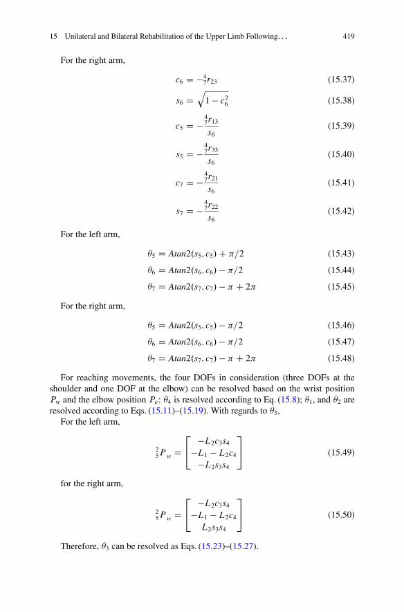
For the left arm,
�5 D Atan2.s5; c5/ C �=2 (15.43)
�6 D Atan2.s6; c6/ � �=2 (15.44)
�7 D Atan2.s7; c7/ � � C 2� (15.45)
For the right arm,
�5 D Atan2.s5; c5/ � �=2 (15.46)
�6 D Atan2.s6; c6/ � �=2 (15.47)
�7 D Atan2.s7; c7/ � � C 2� (15.48)
For reaching movements, the four DOFs in consideration (three DOFs at theshoulder and one DOF at the elbow) can be resolved based on the wrist positionPw and the elbow position Pe: �4 is resolved according to Eq. (15.8); �1, and �2 areresolved according to Eqs. (15.11)–(15.19). With regards to �3,
For the left arm,
25P w D
24
�L2c3s4
�L1 � L2c4
�L2s3s4
35 (15.49)
for the right arm,
25P w D
24
�L2c3s4
�L1 � L2c4
L2s3s4
35 (15.50)
Therefore, �3 can be resolved as Eqs. (15.23)–(15.27).
420 J. Rosen et al.
ForceFields
FrictionCompensation
GravityCompenstataion
RedundancyResolution
ForwardKinematics
DC Motors&
Exoskeleton
HumanArm
Contact ForceSensor
DC MotorsDC Motors
Human Body
Unaffected Arm
Exo Master Exo Slave
Affected Arm
Contact Forces
Gaming Environment
a
b
Trajectories / Targets
Exoskeleton System Human Body
Exoskeleton System
InverseKinematics
PID
X
ddt
PIDPID
PID
KF = 0
S+ ++
+
++
-+
-
-
+t = JTF
S
Sq q
q
q
fd
S
S
ddt
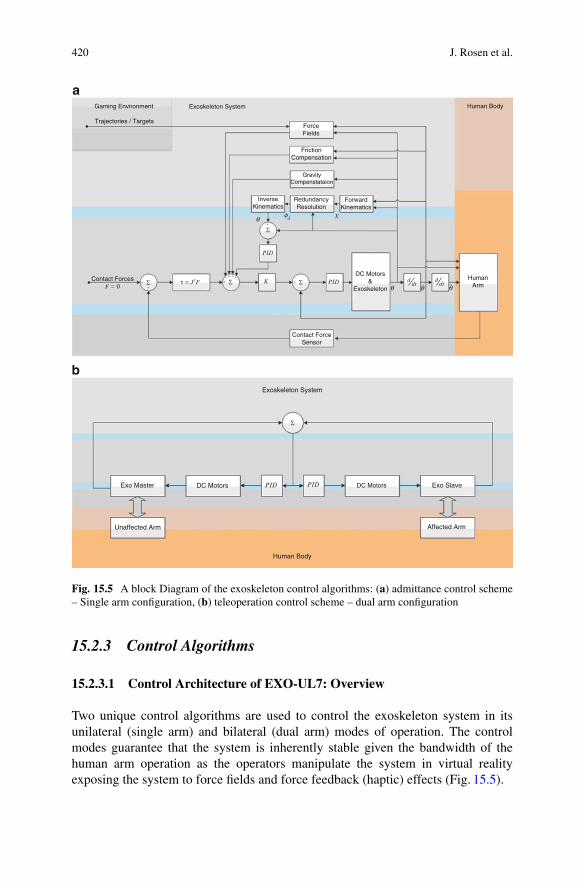
Fig. 15.5 A block Diagram of the exoskeleton control algorithms: (a) admittance control scheme– Single arm configuration, (b) teleoperation control scheme – dual arm configuration
15.2.3 Control Algorithms
15.2.3.1 Control Architecture of EXO-UL7: Overview
Two unique control algorithms are used to control the exoskeleton system in itsunilateral (single arm) and bilateral (dual arm) modes of operation. The controlmodes guarantee that the system is inherently stable given the bandwidth of thehuman arm operation as the operators manipulate the system in virtual realityexposing the system to force fields and force feedback (haptic) effects (Fig. 15.5).
15 Unilateral and Bilateral Rehabilitation of the Upper Limb Following. . . 421
15.2.3.2 Admittance Control: Single Arm Exoskeleton
By definition, An admittance is the dynamic mapping from force to velocity. Anadmittance control scheme utilizes three multi-axis force/torque (F/T) sensors as theprimary inputs. These F/T sensors are attached to all the physical interfaces betweenthe operator’s arm and the exoskeleton at the upper arm, forearm, and palm. A forceapplied on the exoskeleton system by the operator commands the exoskeleton arm tomove with a velocity that is proportional to the force and along the same direction.As the force increases, the system responds by moving faster. This approach is alsoknown as the “get out of the way” control scheme. As the system moves, the controlscheme tries to set the interaction force to zero [34, 35].
15.2.3.3 Teleoperation Control: Dual Arm Exoskeleton
In a teleoperation control scheme, the two arm exoskeleton system is configured as amaster and a slave. The exoskeleton arm attached to the human unaffected (healthy)arm is defined as the master and the other exoskeleton arm attached to the affected(disabled) arm is defined as the slave. A local teleoperation scheme is used in whichthe master arm provides a position commands to the slave arm such that they bothmove in a mirror image fashion. Any joint angle generated by the unaffected armis copied to the affected arm. In this mode of operation the unaffected arm controlsthe movements of the affected arm. The coupling between the arms will be varied.A tight coupling will be induced initially and it will be gradually reduced by 10 %in each treatment such that in the very last treatment, each arm will be completelyindependent (uncoupled).
15.2.3.4 Assistive Modes and Compensation Elements
The assistive modes are designed to further reduce the energy exchange between thehuman arm and the exoskeleton and to improve the transparency of human-robotinteractions. Several force fields are applied on the patients as part on the trainingand their application and magnitude will be a function of the specific task.
Gravity Compensation Joint torques are generated in part due to the gravitationalloads of the exoskeleton arm and the patient’s arm. The gravity compensationalgorithm estimates the joint torques for each arm configuration and provides afeed forward command to the actuators which in turn produce joint torques thatcounter the toque generated by gravity. This compensation will make the weightof the exoskeleton itself transparent to the operator. As such, the operator will feelas if the exoskeleton arm is completely weightless. This compensation mode willbe active at all times. Furthermore, an identical algorithm will compensate for thegravitational loads of the patient’s own arm such that the operator will not feel theweight of his/her arm. This compensation may vary between full compensation and

422 J. Rosen et al.
no compensation. The compensation of the patient’s own arm will change duringthe treatment starting from full compensation during first treatment followed by areduction of 10 % with each treatment that gradually exposes the patient to the fullweight of the arm by the last day of the treatment.
Friction Compensation Friction is a force or a moment that resists the relativemotion of the joints. The static/kinetic (coulomb) friction, as well as viscous frictionis compensated through the feed forward element of the control algorithm such thatthe operator does not feel any resistance associated with friction.
Redundancy Resolution The human arm with its seven DOF (excluding scapularmotion) is a redundant mechanism meaning that there are infinite arm configurationsthat can be adopted for the same position and orientation of the hand for grasping anobject. Passing a virtual axis through the center of the shoulder joint and the centerof the wrist joint allows us to define the position of the elbow joint by an angledefined with respect to this axis. This angle is defined as a swivel angle, which inturn defines in a parametric fashion the redundancy of the arm. Given the anatomicallimitations of the shoulder and the wrist joint, the swivel angle has a specific rangeof angles from which any value to be selected will not change to the position orthe orientation of the hand. The motor control system selects a specific swivel anglewithin the available range, and in that way resolves the arm redundancy. Since thehuman arm and the exoskeleton system are mechanically coupled, the redundancyresolution imposed by the exoskeleton system has to match the same solution thatwould have been adopted by an neuromuscular system. The algorithm implementedinto the exoskeleton is based on an extensive preliminary study of this problemwith both healthy and stroke patients. This algorithm synthesizes three classes ofcriteria: (1) kinematic criteria, (2) dynamic criteria, and (3) comfort criteria. Theweight factors of each one of the three criteria change dynamically and will predictthe swivel angle for the next time interval. One should note that the redundancyresolution is only required in the unilateral mode of operation. During the bilateralmode of operation, the swivel angle of the unaffected arm is transmitted to theaffected arm, thus the exoskeleton system adopts the motor control redundancyresolution.
15.2.4 Redundancy Resolution
The redundancy resolution is critical in the control of the exoskeleton, in order toachieve the transparency of the interaction between the exoskeleton and its operator.Ideally, the redundancy resolution controls the exoskeleton in the same way that thehuman motor system controls arm movements. Therefore, the exoskeleton can beused for power augmentation for the healthy human arm movements, as well as forthe correction of the abnormal arm movements in stroke rehabilitation.

15 Unilateral and Bilateral Rehabilitation of the Upper Limb Following. . . 423
The problem of controlling redundant degrees of freedom, i.e., redundancy res-olution, has been previously considered in the control of robot manipulators. Whensolving an inverse kinematics or dynamics problem for manipulation tasks, redun-dant degrees of freedom can be used to achieve secondary goals such as to satisfycertain task constraints or to improve task performances. Task-based redundancyresolutions control the extra DOF by integrating the task-dependent constraints intoan augmented Jacobian matrix [36, 37]. Performance-based redundancy resolutionsmay optimize the manipulability [19, 38–40], energy consumption [41, 42], thesmoothness of movement [43–46], task accuracy [47] and control complexity [48].
The EXO-UL7 exoskeleton is designed to assist the operator’s arm movementsin unexpected tasks and in uncertain environments. It requires a real-time controlrather than a pre-planned motion control, and the redundancy resolutions haveto be based on local (instead of global) performance optimization. Under theabove constraints, we investigate the study of the motor control of the human armmovements and select several control criteria, which are applicable for the controlof the exoskeleton. The selected criteria optimize different performances in motioncontrol, including motion efficiency, motion smoothness, energy consumptionand etc.
15.2.4.1 Maximizing the Motion Efficiency
H. Kim et al. proposed a redundancy resolution that determines the swivel angle bymaximizing the motion efficiency [19]. As shown in Fig. 15.6, when the elbow fallson the plane formed by the positions of the shoulder Ps , the wrist Pw and the virtualtarget Pm, the projection of the longest principle eigen-vector of the manipulabilityellipsoid on the direction from the hand to the virtual target Pm is maximized, andso is the motion efficiency towards the virtual target Pm, which is hypothesized tobe on the head. Given the role of the head as a cluster of sensing organs and theimportance of arm manipulation to deliver food to the mouth, it is hypothesized thatthe swivel angle is determined by the human motor control system to efficientlyretract the hand to the head region.
A good candidate for the position of virtual target is the position of the mouth.This hypothesis is supported by intracortical stimulation experiments that evokedcoordinated forelimb movements in conscious primates [49,50]. It has been reportedthat each stimulation site produced a stereotyped posture in which the arm movedto the same final position regardless of its posture in the initial stimulation. In themost complex example, a monkey formed a frozen pose with its hand in a graspingposition in front of its open mouth. This implies that during the arm movementtoward an actual target, the virtual target point at the head can be set for the potentialretraction of the palm to the virtual target.

424 J. Rosen et al.
Fig. 15.6 The proposedredundancy resolution intendsto maximize the motionefficiency by maximizing theprojection of the longestprinciple eigen-vector of themanipulability ellipsoid onthe direction from the hand tothe virtual target Pm. Thecorresponding elbow positionfalls on the plane formed byPs , Pw and Pm
15.2.4.2 Minimizing Work in the Joint Space
Minimizing work in the joint space is proposed by T. Kang as a real-timedynamic control criterion, which resolves the inverse kinematics by minimizingthe magnitude of total work done by joint torques for each time step [42]. Withthe dynamic arm model, the joint torques (T ) can be extracted given the states ofthe arm. The calculation of work in the joint space for each time step depends on(1) the joint torques and (2) the difference in joint angles. Therefore, the work in thejoint space during the movement interval Œtk; tkC1� can be computed for two differentconditions. The dynamic constraint adopted in this chapter is from the original workdone by the aerospace medical research laboratory [51]. Here, we briefly include theessential parts of the algorithm for the integrity of the chapter:
if Ti;tk � Ti;tkC1> 0,
Wi D .Ti;tk C Ti;tkC1/ � �qi
2(15.51)
where Ti;tk and Ti;tkC1are the joint torques of the i-th joint at the time tk and tkC1.
�qi D .qi;tkC1�qi;tk / is the difference of the i-th joint angle during the time interval
Œtk; tkC1�.

15 Unilateral and Bilateral Rehabilitation of the Upper Limb Following. . . 425
When Ti;tk � Ti;tkC1< 0,
Wi D .j�qi j � hi / � Ti;tkC1
2� hi � Ti;k
2(15.52)
where hi D .jTi;tk j � j�qi j/=jTi;tkC1� Ti;tk j and denotes the difference of the i-th
joint angle from qi;tk to the value corresponding to the zero crossing of joint torque.To minimize the work done in the joint space at each time step (e.g. jW jtk ;tkC1
forthe time interval Œtk; tkC1�), the swivel angle of the arm for a specified wrist positionis optimized by:
�.k C 1/ D arg min�0.kC1/
jWi jtk ;tkC1
D arg min�0.kC1/
4XiD1
jWi jtk ;tkC1(15.53)
where jWi jtk ;tkC1denotes the work done by the i-th joint.
15.2.4.3 Minimizing Joint Angle Change
Minimizing joint angle change is a real-time kinematic criterion that impose smoothmotion in the joint space. Given the expected positions of the wrist Pw.k C 1/ andthe shoulder Ps.k C 1/, this criterion explores the possible the swivel angles for thenext time step �0.kC1/ and selects the one which minimizes the norm of the changein the joint angle vector. For daily activities, the change in swivel angle within 0:01 sis supposed to be no larger that 0:5ı. Given the current swivel angle �.k/, we searchwithin the range of Œ�.k/ � 0:5; �.k/ C 0:5�ı by the step of ı� D 0:1ı. The swivelangle for the next time step �.k C 1/ is determined by:
�.k C 1/ D arg min�0.kC1/
j�.k/ � � 0.k C 1/j
D arg min�0.kC1/
vuut 4XiD1
.�i .k/ � � 0i .k C 1//2 (15.54)
In Eq. (15.54), �.k/ D Œ�1.k/; �2.k/; �3.k/; �4.k/�T is the joint angle vector forcurrent time step. � 0.k C 1/ is the joint angle vector for the next time step computedfrom a possible �0.k C 1/ value.
At the kinematic level, alternative control criteria can optimize motion smooth-ness by minimizing jerk (the square of the first derivative of acceleration) in thejoint space and/or task space, to account for the straight paths and bell-shaped speedprofiles observed in reaching movements [43, 44, 52]. At the dynamic level, the

426 J. Rosen et al.
optimization of smoothness can be achieved by minimizing the change in jointtorque [45, 46], which explains the mild curvature in the roughly straight hand-reaching trajectories in the task space. By observing various implementations, wehave noticed that minimizing the norm of the change in the joint angle performsbetter than minimizing the norm of the change in higher order derivatives of thejoint angle (e.g., velocity and acceleration). These control strategies are for globalmotion planning and the computation of the trajectories in the task space and/or thejoint space before execution. Since the exoskeleton is designed to move with theoperator in unexpected task and uncertain environment, the smoothness of motionis expected to be addressed more locally than globally.
15.2.4.4 Minimizing the Change in Kinetic Energy
Minimizing the change in kinetic energy is based on the following hypothesis: sincehuman movements are well adapted to gravity, unless the dynamics of the humanbody is significantly affected by additional load, the motor control system may planthe movements at daily-activity speed without compensating much for gravity. Withthe dynamic model, the kinetic energy (Ke) can be computed given the state of thearm. Similar to Criterion 3, we explore the possible swivel angles for the next timestep and find the one that minimizes the change in the kinematic energy.
�.k C 1/ D arg min�0.kC1/
jKe.k/ � Ke0.k C 1/j (15.55)
For global energy optimization, J.F. Soechting et l. minimize the peak valueof kinetic energy, which requires the knowledge of the final arm posture [41]. Inaddition, A. Biess et al. integrate the consideration of kinetic energy in the controlstrategy by looking for a geodesic path in the Riemannian configuration space,which consumes less muscular effort since the sum of all configuration-speed-dependent torques vanishes along the path [53]. For the real-time control of theexoskeleton, we prefer minimizing the change in kinetic energy locally.
15.2.5 Performance Comparison of Different RedundancyResolutions
To study the performance of different redundancy resolutions, we collect data of thepoint-to-point reaching movements in a 3D workspace from healthy subjects (seeFigs. 15.7 and 15.8). The arm postures predicted by different redundancy resolutionsare compared and evaluated with reference to the measured arm postures.
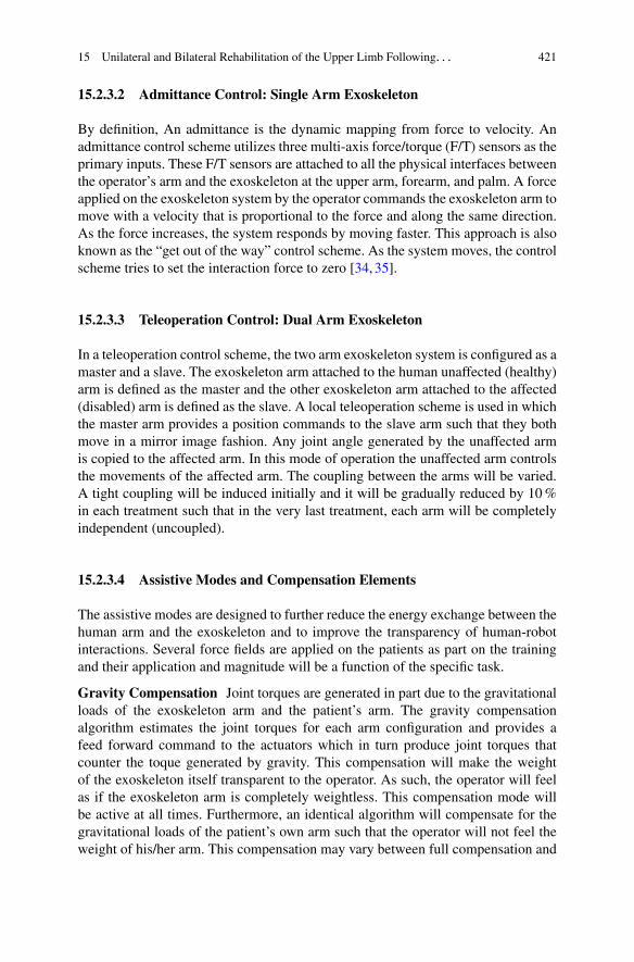
A comparison of the arm posture prediction performance has been conductedbetween the redundancy resolutions by maximizing motion efficiency (RedundancyResolution I) and by minimizing work in the joint space (Redundancy Resolu-tion II). The mean (�) and standard deviation (� ) of the prediction errors are

15 Unilateral and Bilateral Rehabilitation of the Upper Limb Following. . . 427
Fig. 15.7 The spherical workspace for the reaching movement experiments: (a) the top view and(b) the front view. The height of the workspace center is adjustable and is always aligned with theright shoulder of the subject
Fig. 15.8 (a) Eight targets are selected among all the available targets (denotes as blue dots) inthe spherical workspace. Considering the motion range of the right arm, Target 1, 2, 3, 5, 7 (ingreen circles) are within the comfortable arm motion range, while Target 4, 6, and 8 (in magentacircles) are close to the motion range boundary. (b) A subject is performing the instructed reachingmovement. The subject is seated in a chair with a straight back support. The right arm is freefor reaching movements, while the body of the subject is bounded back to the chair to minimizeshoulder displacement. During the experiment, the subject uses index finger to point from oneinstructed target to another, with his/her wrist kept straight. A motion capture system catches thepositions of the passive-reflective markers attached to the torso and the right arm, recording themovements at 100 Hz

428 J. Rosen et al.
computed for each individual valid trail (2,674 out of 2,800 in total), and theirdistributions are presented in Fig. 15.9. It is shown that the Redundancy ResolutionII has higher performance on both the mean and standard deviation of the predictionerrors, which results from the fact that Redundancy Resolution II has to startits prediction from the arm posture measured at the beginning of the movement,while Redundancy Resolution I does not need to initialize its prediction with anymeasured data. One way to improve the performance of Redundancy ResolutionI is to estimate the position of the virtual target dynamically based on the recenthistory of the swivel angle measurements. As shown in Fig. 15.9e,f, the improvedperformance is slightly higher than that of Redundancy Resolution II [54].
15.3 Clinical Study: Application of EXO-UL7on Stroke Rehabilitation
15.3.1 Experiment Protocols
15.3.1.1 Apparatus
The system used for this research consisted of the upper limb exoskeletonEXO-UL7, a control computer, and a game computer. The control computerused PID control to provide gravity compensation, as well as bilateral symmetricassistance or unilateral assistance, as needed. In all cases where assistance wasprovided, the robot only provided partial assistance, helping subjects by giving ahelpful push in the desired direction [6, 7, 55].
The games were created using Microsoft Robotic Developer Studio [56]. Thegame computer was connected to a 5000 flat screen monitor. In addition to generatingreal time virtual reality [57] game images, the game computer also collected positionand force data at 100 Hz.
The games are depicted in Fig. 15.10. The games were played for 10–15 mineach. Over the course of the study, each subject played every game multiple times.Therefore, the rehabilitative efficacy of any given game is confounded with the othergames [58]. The BSRMT group played each game using both arms and the URMTgroup played each game using only the paretic arm. For BSRMT, the subject’sless-affected arm was the master, and the paretic arm was the slave. As subjectsmoved their less-affected arm the robot moved the paretic arm in a mirror-imagefashion. Aside from gravity compensation, for URMT, the robot only providedpartial assistance in the Flower game (see Fig. 15.1a). A more detailed evaluation ofthese games is provided in [6].
15 Unilateral and Bilateral Rehabilitation of the Upper Limb Following. . . 429
0 10 20 300
0.05
0.1
0.15
0.2
0.25
0.3a b
c d
e f
μ (deg)
prob
Mean of errors.
0 10 20 300
0.05
0.1
0.15
0.2
0.25
0.3
σ (deg)
prob
Standard deviation of errors.
0 10 20 300
0.05
0.1
0.15
0.2
0.25
0.3
μ (deg)
prob
Mean of errors.
0 10 20 300
0.05
0.1
0.15
0.2
0.25
0.3
σ (deg)
prob
Standard deviation of errors.
0 10 20 300
0.1
0.2
μ (deg)
prob
Mean of errors.
0 10 20 300
0.1
0.2
σ (deg)
prob
Standard deviation of errors.
Fig. 15.9 Swivel angle prediction performance of the redundancy resolutions by maximizing themotion efficiency (the Redundancy Resolution I, see (a) and (b)) and by minimizing the workin joint space (the Redundancy Resolution II, see (c) and (d)). The performance of RedundancyResolution I can be improved by dynamic estimation of the position of the virtual target (see (e)and (f))

430 J. Rosen et al.
Fig. 15.10 Screen shots from the various games. The avatar arms move in response to themovement of the subject. In the Pinball and Circle games, avatar arms are not visible so that theview of the Pingpong table will not be blocked. (a) Flower game. (b) Paint game. (c) Reach game.(d) Pong game. (e) Pinball game. (f) Circle game. (g) Handball game
15.3.1.2 Pilot Study
Ten male and female subjects between 27 and 70 years of age, for more than6 months post stroke, with a Fugl-Meyer score between 16 and 39 and a score of19 or greater on the VA Mini Mental Status Exam were recruited for the study.All were screened and consented prior to a random assignment. The subjects weresub-categorized by severity and then randomly assigned to either the unilateralrobotic training or to the bilateral robotic training. All subjects were scheduled for12 training sessions. The visits were scheduled twice a week for 6 weeks. This studywas approved by the Committee on Human Research at the University of California-San Francisco (UCSF) and each session was preformed at UCSF under the guidanceof a trained therapist.
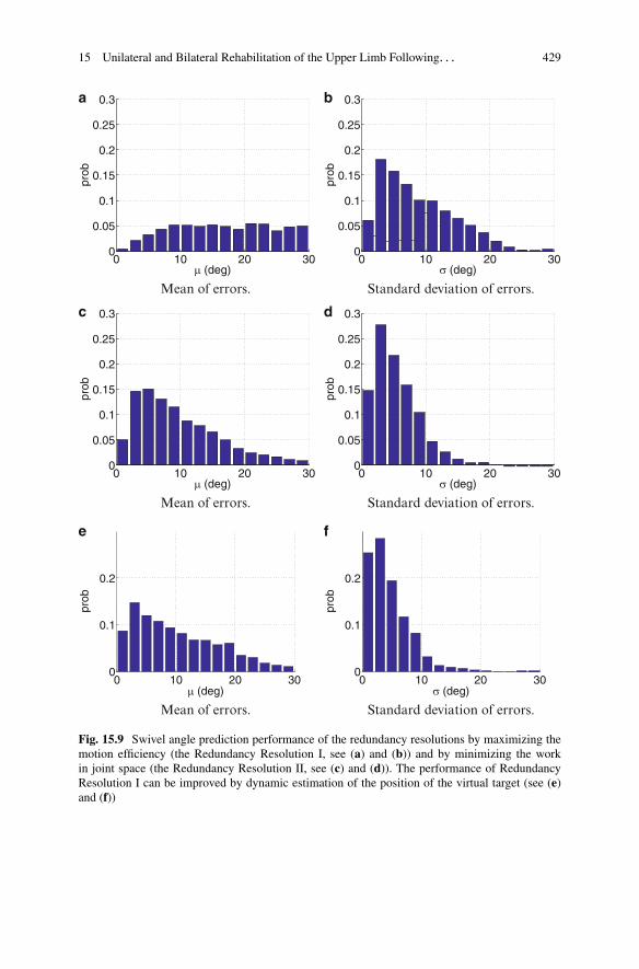
In the pilot study, subjects sit in front of a screen with a virtual reality game toplay. In this game, small target balls are located spherically around the robot. Whenthe target balls with the tip of the virtual arm is touched, the ball color changes (seeFig. 15.11). The ratio of the touched balls to the total number of target balls can beused to assess the mobility improvement of the subjects.
15.3.1.3 Unilateral and Bilateral Robotic Training via the EXO-UL7
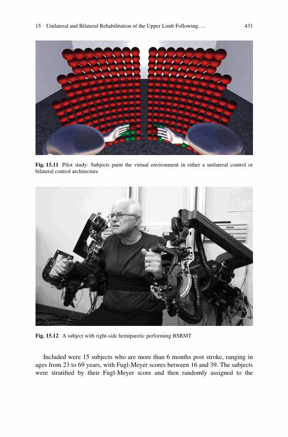
The research on the unilateral and bilateral robotic training was approved by theUniversity of California, San Francisco, Committee on Human Research. Inter-ventions consisted of 12, 90-min sessions of robotic assisted training or standardcare. An elastic restraint around the torso and thighs helped subjects maintain aneutral sitting position during robotic training. The experimental setup is depictedin Fig. 15.12.
15 Unilateral and Bilateral Rehabilitation of the Upper Limb Following. . . 431
Fig. 15.11 Pilot study: Subjects paint the virtual environment in either a unilateral control orbilateral control architecture
Fig. 15.12 A subject with right-side hemiparetic performing BSRMT
Included were 15 subjects who are more than 6 months post stroke, ranging inages from 23 to 69 years, with Fugl-Meyer scores between 16 and 39. The subjectswere stratified by their Fugl-Meyer score and then randomly assigned to the
432 J. Rosen et al.
BSRMT, URMT or usual care with a physical therapist. With an upper limb Fugl-Meyer score between 16 and 39, each subject had the necessary control of theirparetic arm to be able to play the games, while still having the potential forimprovement.
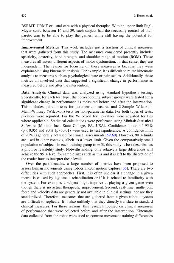
Improvement Metrics This work includes just a fraction of clinical measuresthat were gathered from this study. The measures considered presently include:spasticity, dexterity, hand strength, and shoulder range of motion (ROM). Thesemeasures all assess different aspects of motor dysfunction. In that sense, they areindependent. The reason for focusing on these measures is because they wereexplainable using kinematic analysis. For example, it is difficult to relate kinematicanalysis to measures such as psychological state or pain scales. Additionally, thesemetrics all involved data that suggested a significant change in performance asmeasured before and after the intervention.
Data Analysis Clinical data was analyzed using standard hypothesis testing.Specifically, for each test type, the corresponding subject groups were tested for asignificant change in performance as measured before and after the intervention.This includes paired t-tests for parametric measures and 2-Sample Wilcoxon-Mann-Whitney (Wilcoxon) tests for non-parametric data. For both types of tests,p-values were reported. For the Wilcoxon test, p-values were adjusted for tieswhere applicable. Statistical calculations were performed using Minitab StatisticalSoftware (Minitab Inc., State College, PA, USA). Confidence limits of 95 %(p < 0.05) and 90 % (p < 0.01) were used to test significance. A confidence limitof 90 % is generally not used for clinical assessments [59,60]. However, 90 % limitsare used in other contexts, albeit as a lower limit. Given the comparatively smallpopulation of subjects in each training group (n D 5), this study is best described asa pilot, or feasibility study. Notwithstanding, only relatively large differences willachieve the 95 % level for sample sizes such as this and it is left to the discretion ofthe reader how to interpret these levels.
Over the past decades, a large number of metrics have been proposed toassess human movements using robots and/or motion capture [55]. There are twodifficulties with such approaches. First, it is often unclear if a change in a givenmetric is caused by legitimate rehabilitation or if it is related to familiarity withthe system. For example, a subject might improve at playing a given game eventhough there is no actual therapeutic improvement. Second, real-time, multi-jointforce and velocity data are generally not available in clinical settings, nor are theystandardized. Therefore, measures that are gathered from a given robotic systemare difficult to replicate. It is also unlikely that they directly translate to standardclinical measures. For these reasons, this research focused on clinical measuresof performance that were collected before and after the intervention. Kinematicdata collected from the robot were used to contrast movement training differences

15 Unilateral and Bilateral Rehabilitation of the Upper Limb Following. . . 433
between BSRMT and URMT modes, but not as a measure of improvement. For adetailed analysis of subject performance using kinematic data collected from therobot, see [16].
The Data Analysis Section references joints by number. The directions of positivejoint rotation are depicted in Fig. 15.2. In words, the axes are defined as follows:Joint 1 is a combination of shoulder flexion and abduction; Joint 2 is a combinationof shoulder flexion and adduction; Joint 3 shoulder inner rotation, Joint 4, elbowflexion; Joint 5 is the elbow/wrist supination; Joint 6 is the wrist flexion; and joint 7is the wrist ulnar deviation.
In an effort to tie the clinical outcomes to training, a metric is needed to quantifyoverall movement training. A long-standing tenet in the rehabilitation community isthat repetition of movement is required for recovery. To quantify overall movementtraining for a given game during a given trial, seven numbers are calculated, onefor each joint. Each of the seven numbers relate to the proportional contribution ofmovement for a given joint. An eighth number is calculated to capture the overallintensity of movement. With respect to the proportions of movement for each of theseven joints, a row vector is defined as Eq. (15.56):
ˇp1 p2 p3 p4 p5 p6 p7
ˇ(15.56)
where p1 is the proportion of rotation for joint 1, p2 is the proportion of rotationof joint 2, and so on. Accordingly,
ˇP7iD1 pi D 1
ˇ(15.57)
Thus, the sum of the proportions account for 100 % of the total joint rotation forthe 7 DOF of the arm. The 8th number being calculated is the “intensity” of thetraining and is given by I. Thus, the intensity of training for joint j is given by pj
PI .Equations (15.56) to (15.57) require some measure of movement training
intensity. One approach is to calculate the total angular position, velocity, andacceleration for a given joint. As a start, consider the angular position. A changein the angular position is given as �. Summing � for successive samples inthe data set is infeasible because rotations in one direction will be canceled withrotations in the other direction. Therefore, a more suitable calculation for the angularposition of the j-th joint is to take the RMS as follows:
RMSj Dvuut 1
n
nXi�1
�i;j (15.58)
were n is the number of joint measurements, and i is the ith measurement.Angular velocity, ! is given by �=�t . Therefore, the RMS for ! is given by
434 J. Rosen et al.
RMS!;j Dvuut 1
n
nXi�1
.�i;j
Ts
/2 (15.59)
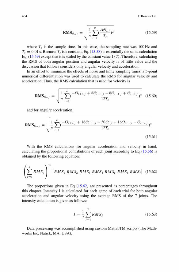
where Ts is the sample time. In this case, the sampling rate was 100 Hz andTs D 0:01 s. Because Ts is a constant, Eq. (15.58) is essentially the same calculationEq. (15.59) except that it is scaled by the constant value 1=Ts . Therefore, calculatingthe RMS of both angular position and angular velocity is of little value and thediscussion that follows considers only angular velocity and acceleration.
In an effort to minimize the effects of noise and finite sampling times, a 5-pointnumerical differentiation was used to calculate the RMS for angular velocity andacceleration. Thus, the RMS calculation that is used for velocity is
RMS!;j Dvuut 1
n
nXi�1
.�iC2;j C 8iC1;j � 8i�1;j C i�2;j
12Ts
/2 (15.60)
and for angular acceleration,
RMS!;j Dvuut 1
n
nXi�1
.�iC2;j C 16iC1;j � 30i;j C 16i�1;j � i�2;j
12Ts
/2
(15.61)
With the RMS calculations for angular acceleration and velocity in hand,calculating the proportional contributions of each joint according to Eq. (15.56) isobtained by the following equation:
0@
nXj D1
RMSj
1A
�1
ˇRMS1 RMS2 RMS3 RMS4 RMS5 RMS6 RMS7
ˇ(15.62)
The proportions given in Eq. (15.62) are presented as percentages throughoutthis chapter. Intensity I is calculated for each game of each trial for both angularacceleration and angular velocity using the average RMS of the 7 joints. Theintensity calculation is given as follows:
I D 1
7
7Xj D1
RMSj (15.63)
Data processing was accomplished using custom MatlabTM scripts (The Math-works Inc, Natick, MA, USA).

15 Unilateral and Bilateral Rehabilitation of the Upper Limb Following. . . 435
15.3.2 Results
15.3.2.1 Pilot Study
During the clinical trial for the paint game, the travel distance and time-to-finishwere recorded. Averaged travel distances show that the bilateral training grouptraveled 2.2 m/session and unilateral group did 1 m/session. The bilateral groupspent 22 s/session and unilateral group spent 12 s/session. The percent improvementdefined between the first and last session 12 weeks later showed that the bilateral andunilateral training group had 97 and 2 % improvement, respectively for the traveldistance, while both groups showed similar improvement for time-to-finish [16].
15.3.2.2 Clinical Outcomes of the Unilateral and BilateralRobotic Training
Clinical Measures Non-parametric data are summarizes in Figs. 15.13–15.16 andparametric data are summarized in Figs. 15.17–15.19. For each group the averagepercent change is calculated for parametric data. For non-parametric data themedian change is calculated. Also, a p-value for the corresponding hypothesistest (Wilcoxon or paired-t test) is given below each plot. The bold type indicatessignificant differences. The strongest changes, ˛ � 0:05, are distinguished with adark shade of box plot gray for parametric data. For 0:05 < ˛ � 0:10, the box plotsare distinguished with a lighter shade of gray.
There was a statistically significant reduction in finger flexion (see Fig. 15.13b),and elbow flexion/extension spasticity for URMT, see Fig. 15.13c, d, as well as asignificant improvement on the Box and Block Test (see Fig. 15.17b). However,there was a significant reduction in grip strength for URMT, as measured with aJamar hand dynamometer (Lafayette Instrument Company, Lafayette, IN).
There were significant differences for ROM [61] in the shoulder for all threegroups, see Fig. 15.18e–g. All ROM measurements were performed with a goniome-ter. There was a relatively large improvement in shoulder abduction for the BSRMT,see Fig. 15.18e, and the standard care groups. The subjects in the BSRMT group alsohad significant improvements for shoulder external rotation ROM, see Fig. 15.18g.The URMT group had the least improvement in shoulder ROM. In addition, theBSMRT group had a significant reduction in internal rotation ROM at the shoulder,see Fig. 15.18f.
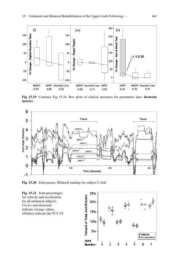
Movement Training Measures At times subjects would pause their movementtraining. Causes for such halting could result from a variety of reasons. Examplesinclude: stops for technical corrections for the robot or game, readjustments ofstraps or restraints, dialog with the subjects, respites, and bathroom breaks. As aspecific example, a training interval of approximately 300 s is depicted in Fig. 15.20.

436 J. Rosen et al.
Fig. 15.13 Individual value plots of clinical measures for non-parametric data: spasticity metrics.Individual values represent percent improvements as measured before and after the intervention.Also depicted are significant (p � 0:05), or marginally significant (p � 0:10) changes asdetermined by a Wilcoxon test. Connecting lines attach median values. Note, for cases where adecrease in a metric is regarded as an improvement the individual values are given positive, andvice-a-versa

15 Unilateral and Bilateral Rehabilitation of the Upper Limb Following. . . 437
Fig. 15.14 Continue Fig. 15.13. Individual value plots of clinical measures for non-parametricdata: phvchological metrics
Fig. 15.15 Continue Fig. 15.14. Individual value plots of clinical measures for non-parametricdata: general metrics
Notice that there are two apparent pauses wherein most of the joints stop moving(flat lines). Pauses such as this will deflate the measures given by Eq. (15.60) andEq. (15.61). Perhaps the most accurate measure of training intensity Eq. (15.63) andpercent contributions Eq. (15.62) would consider only data with the pauses removed.However, such segregation of data is open to interpretation and is fought withuncertainty. For this reason, the following analysis will consider data sets only forthe top 50-th percentile of training as measured by intensity. Cases where training is

438 J. Rosen et al.
Fig. 15.16 Continue Fig. 15.15. Individual value plots of clinical measures for non-parametricdata: strength metrics
halted will result in lower intensities. Therefore, by excluding the lower half of thedata, it is more assured that data analysis only includes training that was continuousand without interruption.
Figure 15.23 depicts URMT percentage contributions by joint for veloc-ity Eq. (15.60) and acceleration Eq. (15.61). Each element in Eq. (15.62) issummarized statistically as a CI for velocity and acceleration. Notice that angular

15 Unilateral and Bilateral Rehabilitation of the Upper Limb Following. . . 439
Fig. 15.17 Box plots of clinical measures for parametric data: hand strength metrics. Individualvalues represent percent improvements as measured before and after the intervention. Alsodepicted are significant (p � 0:05), or marginally significant (p � 0:10) changes as determinedby a paired t-test. Connecting lines attach mean values
velocity and acceleration track are fairly close for each joint. In general, based onthe percent contributions of each joint, and the training intensities, velocity andacceleration tended to co-vary. Putting it in another way, comparison of BSRMTand URMT by velocity was roughly equivalent to using acceleration. Therefore,considering the differences between BSRMT and URMT in terms of velocity andacceleration are of little value. Thus, with the proviso that acceleration would havebeen an equally valid measure, the remainder of this chapter will consider onlyvelocity RMS values.
Depicted in Fig. 15.21 is a comparison of the affected arm to the control armfor BSRMT. Perhaps not surprisingly, the control arm had similar joint contributionpercentages as the affected hemiparetic arm. However, in terms of intensity, theaffected was significantly lower than the control arm, p D 0:017, see “All joints”in Fig. 15.22.
Bilateral Symmetric Versus Unilateral Training Because the improvement ofthe affected side is most important, the following comparison between BSRMTand URMT considers only the paretic arms. This comparison is summarizedin Fig. 15.23. The most important difference was in terms of intensity. The rightmost set of CI’s in Fig. 15.9 depicts the overall intensity of bilateral versus unilateraltraining as calculated by Eq. (15.63). A 2-sample t-test indicated that there wasa statistically significant difference in intensity between the two training groups(p � value < 0:001) with BSRMT having a mean intensity that was 25 %higher than URMT. Additionally, Fig. 15.23 shows that the BSRMT resulted in ahigher proportion of movement for Joint 4 (elbow). Thus, the EXO-UL7 imposedsignificantly higher velocities on the wrist and elbow as it attempted to maintainsymmetry between the paretic arm and the faster moving unaffected arm.

440 J. Rosen et al.
Fig. 15.18 Continue Fig. 15.17. Box plots of clinical measures for parametric data: range ofmotion metrics
15 Unilateral and Bilateral Rehabilitation of the Upper Limb Following. . . 441
Fig. 15.19 Continue Fig. 15.18. Box plots of clinical measures for parametric data: dexteritymetrics
Fig. 15.20 Joint pauses. Bilateral training for subject 5, trial
Fig. 15.21 Joint percentagesfor velocity and accelerationfor all unilateral subjects.Circles and diamondsindicate average values,whiskers indicate the 95 % CI

442 J. Rosen et al.
Fig. 15.22 Bilateral percentcontributions by joint of thecontrol arm (unimpairedarm), versus the slave(affected) arm given as 95 %CIs with mean values
Fig. 15.23 BSRMT versusURMT given as 95 % CIswith mean values
15.4 Discussion
15.4.1 Pilot Study
Patients played the therapy game longer in the bilateral mode with admittancecontrol compared to the unilateral mode and the bilateral group showed moreactivity for a given therapy session. We can infer that the bilateral with admittancecontrol helped patients spend more time on the therapy compared to the unilateraltraining group. In physical therapy, it is important to expose the patients to thetherapy for as long as possible to maximize the efficiency of the therapy. Thereis great promise in using assistive methods such as the bilateral with admittancecontrol to improve the therapy results even if it is just by allowing patients to toleratelonger session.
15.4.2 Unilateral vs Bilateral Robotic Training
In this stroke study, there were significant differences in clinical gains followingBSRMT versus URMT. The URMT group experienced a greater decrease in tone

15 Unilateral and Bilateral Rehabilitation of the Upper Limb Following. . . 443
and the BSRMT group demonstrated greater gains in ROM. Using the approachdescribed in the Data Analysis section, position, velocity, and acceleration wereapproximately equivalent measures. This approach also allowed for a more detailedcomparative analysis of training. With respect to differences between the lessaffected control arm and the affected arm for BSRMT, the paretic arm did not alwaysmove as far, or as fast as the less affected arm. This difference is explainable by thefact that the robot only provided partial assistance. Recall that the EXO-UL7 onlyprovides a helpful push for the paretic arm. Therefore, for USRMT involving partialassistance, the less affected arm will move more vigorously than the affected arm.
For the Box and Block test, there was a significant improvement for URMTsubjects. Given that this test involves grasping blocks and transporting them overa barrier [62], improved performance on the Box and Block test was likely relatedto grasping improvements: reductions in spasticity in the hand and elbow, as wellas improved ROM in the shoulder. The changes in grasping strength for URMTare somewhat puzzling. The EXO-UL7 provides no means to explicitly exercisethe hand. Instead, subjects simply grasp a handle while performing training. TheEXO-UL7 does not measure gripping force in the hand. Therefore, an explanationfor reduced grip strength is somewhat speculative. Notwithstanding, a reduction inhand strength has been associated with reduced spasticity [63]. Thus, like the Boxand Block test, reductions in hand strength might relate to reduced spasticity.
The analysis of kinematic data showed that BSRMT was associated with highervelocities of movements in the hand and elbow than URMT. Rapid extension ofspastic muscles is generally regarded as undesirable. Thus, if reduction in spasticityof the elbow and/or hand is a therapeutic goal, BSRMT should be avoided. IfBSRMT is used, precautions are needed to ameliorate the deleterious effects ofrapid symmetric movements on the wrist and elbow. One solution could be to adjustthe symmetric control algorithm. This adjustment might limit the joint speeds inthe paretic elbow and wrist. However, this would lead to asymmetrical rather thansymmetrical movements. An alternative approach could involve a control schemein which speed is limited for the unaffected arm. For example, providing a viscoussensation in the unaffected wrist and elbow would reduce the velocities in both armsand preserve symmetry. Unilateral robotic training has shown promising results inother stroke studies [11,64,65]. With such precautions in place, BSRMT might havehad comparably good results with URMT in terms of reduced spasticity in the elbowand wrist.
Given that all three training groups had some improvement in terms of ROM inthe shoulder, these results could be interpreted as an indication that ROM in theshoulder was generally more amenable to an intervention. The range of motion wasmost improved in the shoulder for the BSRMT. It was significantly improved in thestandard care groups but results were mixed for the URMT group. It is not clearhow improved shoulder ROM for BSRMT is explainable by a greater cross-talkbetween the hemispheres of the brain. Indeed, BSRMT is unique from other typesof robotic assistance in that the movements are self-guided by the patient. In thisrespect, the movements imposed on the paretic arm are literally a reflection of how,and when a subject chose to move their arm. Self-generated BSRMT did result inmore intense training of the paretic arm. Thus, improvement in ROM may have

444 J. Rosen et al.
resulted simply from greater intensity, and potentially more natural movements ofthe paretic shoulder. Lacking more direct measures of neurological activities, wefind it exceedingly difficult to make conclusions about the effects of robotic trainingon hemispheric changes in connectivity with kinematic measures alone.
References
1. Kagerer F, Summers J, Semjen A (2003) Instabilities during antiphase bimanual movements:are ipsilateral pathways involved?. Exp Brain Res 151:489–500
2. Cattaert D, Semjen A, Summers J (1999) Simulating a neural cross-talk model for between-hand interference during bimanual circle drawing. Biol Cybern 81:343–358
3. Yavuzer G, Selles R, Sezer N, Sutbeyaz S, Bussmann J, Koseoglu F, Atay M, Stam H (2008)Mirror therapy improves hand function in subacute stroke: a randomized controlled trial. BiolCybern 89:393–398
4. Sutbeyaz S, Yavuzer G, Sezer N, Koseoglu B (2007) Mirror therapy enhances lower-extremitymotor recovery and motor functioning after stroke: a randomized controlled trial. Arch PhysMed Rehabil 88(5):555–559
5. Cauraugh J, Kim S, Duley A (2005) Coupled bilateral movements and active neuromuscularstimulation: intralimb transfer evidence during bimanual aiming. Neurosci Lett 382(1–2):39–44
6. Simkins M, Fedulow I, Kim H, Abrams G, Byl N, Rosen J (2012) Robotic rehabilitation gamedesign for chronic stroke. Games Health J 1(6):422–430
7. Lum P, Burgar C, Shor P, Majmundar M, Loos MVD (2002) Robot-assisted movement trainingcompared with conventional therapy techniques for the rehabilitation of upper-limb motorfunction after stroke. Am Congr Rehabil Med Am Acad Phys Med Rehabil 83:952–959
8. Perry JC, Rosen J, Burns S (2007) Upper-limb powered exoskeleton design. Mechatronics12(4):408–417
9. Perry JC, Rosen J (2006) Design of a 7 degree-of-freedom upper-limb powered exoskeleton.In: IEEE/RAS-EMBS international conference on biomedical robotics and biomechatronics,Pisa
10. Krebs HI, Ferraro M, Buerger SP, Newbery MJ, Makiyama A, Sandmann M, Lynch D, VolpeBT, Hogan N (2004) Rehabilitation robotics: pilot trial of a spatial extension for mit-manus.J NeuroEng Rehabil 1:5
11. Krebs HI, Hogan N, Aisen ML, Volpe BT (2007) Robot-aided neurorehabilitation: a robot forwrist rehabilitation. IEEE Trans Neural Syst Rehabil Eng 15(3):327–335
12. Reinkensmeyer D, Wolbrecht E, Bobrow J (2007) A computational model of human-robot loadsharing during robot-assisted arm movement training after stroke. In: Conf Proc IEEE Eng MedBiol Soc 2007:4019–4023
13. Majumdar S (1995) Pneumatic system: principles and maintenance. Tata McGraw-Hill, NewDelhi
14. He J, Koeneman EJ, Schultz RS, Huang H, Wanberg J, Herring DE, Sugar T, Herman R,Koeneman JB (2005) Design of a robotic upper extremity repetitive therapy device. In: ICORR2005, Chicago
15. He J, Koeneman EJ, Schultz RS, Herring DE, Wanberg J, Huang H, Sugar T, Herman R,Koeneman JB (2005) Rupert: a device for robotic upper extremity repetitive therapy. In: EMBS2005, Shanghai
16. Kim H, Miller L, Fedulow I, Simkins M, Abrams G, Byl N, Rosen J (2013) Kinematic dataanalysis for post-stroke patients following bilateral versus unilateral rehabilitation with anupper limb wearable robotic system. IEEE Trans Neural Syst Rehabil Eng 21(2):153–164
17. Perry J, Powell J, Rosen J (2009) Isotropy of an upper limb exoskeleton and the kinematicsand dynamics of the human arm. J Appl Bionics Biomech 6(2):175–191
15 Unilateral and Bilateral Rehabilitation of the Upper Limb Following. . . 445
18. Rosen J, Perry J (2007) Upper limb powered exoskeleton. J Humanoid Robot 4(3):1–2019. Kim H, Miller L, Rosen J (2011) Redundancy resolution of a human arm for controlling a
seven dof wearable robotic system. In: EMBC 2011, Boston20. Kim H, Li Z, Milutinovic D, Rosen J (2012) Resolving the redundancy of a seven dof wearable
robotic system based on kinematic and dynamic constraint. In: ICRA 2012, St. Paul21. Miller LM, Rosen J (2010) Comparison of multi-sensor admittance control in joint space and
task space for a seven degree of freedom upper limb exoskeleton. In: Proceedings of the 3rdIEEE RAS & EMBS international conference on biomedical robotics and biomechatronics,Tokyo, pp 26–29
22. Kallmann M (2008) Analytical inverse kinematics with body posture control. Comput AnimatVirtual Worlds (CAVW) 19(2):79–91
23. Lee P, Wei S, Zhao J, Badler NI (1990) Strength guided motion. Comput Graph 24:253–26224. Iossifidis I, Steinhage A (2002) Controlling a redundant robot arm by means of a haptic sensor.
In: ROBOTIK 2002, pp 269–27425. Korein JU (1985) A geometric investigation of reach. MIT, Cambridge26. Perry J, Rosen J (2006) Design of a 7 degree-of-freedom upper-limb powered exoskeleton. In:
Proceedings of the 3rd IEEE RAS & EMBS international conference on biomedical roboticsand biomechatronics, Pisa, pp 805–810
27. Tsagarakis N, Caldwell DG (2003) Development and control of a ‘Soft-Actuated’ exoskeletonfor use in physiotherapy and training. Auton Robot 15(1):21–33
28. Wang X (1999) A behavior-based inverse kinematics algorithm to predict arm prehensionposture for computer-aided ergonomic evaluation. J Biomech 32(5):453–460
29. Zhang X, Chaffin DB (1999) The effects of speed variation on joint kinematics duringmultisegment reaching movements. Hum Mov Sci 18:741–757
30. Yang F, Yuan X (2003) An inverse kinematical algorithm for human arm movement withcomfort level taken into account. In: Proceedings of 2003 IEEE conference on controlapplications, Istanbul, Turkey, pp 1296–1300
31. Garner B, Pandy M (1999) Final posture of the upper limb depends on the initial position of thehand during prehension movements. Comput Methods Biomech Biomed Eng 2(2):107–124
32. Badler NI, Tolani D (1996) Real-time inverse kinematics of the human arm. Presence5(4):393–401
33. Craig J (2003) Introduction to robotics: mechanics and control, 3rd edn. Prentice Hall, Harlow,ch 1
34. Yu W, Rosen J, Li X (2011) Admittance control for an upper limb exoskeleton, 2011american control conference. In: 2011 American control conference – ACC, San Francisco,pp 1124–1129
35. Kim H, Miller LM, Rosen J (2012) Admittance control of seven-dof upper limb exoskeleton toreduce energy exchange. In: ICRA 2012, Saint Paul, pp 1–4
36. Sciavicco L (1987) A dynamic solution to the inverse kinematic problem for redundantmanipulators. In: ICRA 1987, vol 4. Raleigh, NC, USA, pp. 1081–1087
37. Sciavicco L (1988) A solution algorithm to the inverse kinematic problem for redundantmanipulators. IEEE Trans Robot Automat 4(4):403–410
38. Asada H, Granito J (1985) Kinematic and static characterization of wrist joints and theiroptimal design. In: ICRA 1985, St. Louis, pp 244–250
39. Yoshikawa T (1985) Dynamic manipulability of robot manipulators. In: ICRA 1985, St. Louis,pp 1033–1038
40. Yoshikawa T (1990) Foundations of robotics: analysis and control. MIT, Cambridge41. Soechting J, Buneo C, Herrmann U, Flanders M (1995) Moving effortlessly in three dimen-
sions: does donders’ law apply to arm movement? J Neurosci 15(9):6271–628042. Kang T, He J, Tillery SIH (2005) Determining natural arm configuration along a reaching
trajectory. Exp Brain Res 167:352–36143. Hogan N (1984) An organizing principle for a class of voluntary movements. J Neurosci
4(2):2745–2754
446 J. Rosen et al.
44. Flash T, Hogan N (1985) The coordination of arm movements: an experimentally confirmedmathematical model. J Neurophysiol 5:1688–1703
45. Uno Y, Kawato M, Suzuki R (1989) Formation and control of optimal trajectory in humanmultijoint arm movement – minimum torque-change model. Biol Cybern 61:89–101
46. Nakano E, Imamizu H, Osu R, Uno Y, Gomi H, Yoshioka T, Kawato M (1999) Quantitativeexaminations of internal representations for arm trajectory planning: minimum commandedtorque change model. J Neurophysiol 81(5):2140–2155
47. Harris CM, Wolpert DM (1998) Signal-dependent noise determines motor planning. Nature194:780–784
48. Todorov E, Jordan MI (2002) Optimal feedback control as a theory of motor coordination.Nat Neurosci 5:1226–1235
49. Duma RP, Strick PL (2002) Motor areas in the frontal lobe of the primate. Physiol Behav77:677–682
50. Graziano MS, Taylor CS, Moore T (2002) Complex movements evoked by micro stimulationof precentral cortex. Neuron 34:841–851
51. Aerospace medical research laboratory (1975) Investigation of inertial properties of humanbody, Tech rep, Mar 1975
52. Wada Y, Kaneko Y, Nakano E, Osu R, Kawato M (2001) Quantitative examinations for multijoint arm trajectory planningusing a robust calculation algorithm of the minimum commandedtorque change trajectory. J Neural Netw 14:381–393
53. Biess A, Liebermann D, Flash T (2007) A computational model for redundant human three-dimensional pointing movements: integration of independent spatial and temporal motor planssimplifies movement dynamics. J Neurosci 27:13 045–064
54. Li Z, Roldan J, Milutinovic D, Rosen J (2013) The rotational axis approach for resolving thekinematic redundancy of the human arm in reaching movements. In: EMBC 2013, Osaka,pp 1–4
55. Secoli R, Milot MH, Rosati G, Reinkensmeyer D (2011) Effect of visual distraction andauditory feedback on patient effort during robot-assisted movement training after stroke.J Neuroeng Rehabil 8:21
56. Microsoft. Microsoft robotic developer studio 2008. (Online). Available: http://www.microsoft.com
57. Krakauer JW (2006) Motor learning: its relevance to stroke recovery and neurorehbilitation.Curr Opin Neurol 19(1):84–90
58. Kato PM (2012) Games for health journal: evaluating efficacy and validating games for health.Curr Opin Neurol 1(1):74–76
59. B U S of Public Health. Random error. (Online). Available: sph.bu.edu/otit/MPH-Modules/EP/EP713-RandomError-print.html
60. Taub E, Uswatte G, Pidikiti R (1999) Constraint-induced movement therapy: a new family oftechniques with broad application to physical rehabilitation–a clinical review. J Rehabil ResDev 36(3):237–251
61. Andrews A, Bohannon R (1989) Decreased shoulder range of motion on paretic side afterstroke. Phys Ther 69(9):768–772
62. Mathiowetz V, Volland G, Kashman N, Wever K (1985) Adult norms for the box and block testof manual dexterity. Am J Occup Ther 39(6):386–391
63. O’Dwyer N, Ada L, Neilson P (1996) Spasticity and muscle contracture following stroke. Brain119(Pt5):1737–1749
64. Prange G, Jannink M, Groothuis-Oudshoorn C, Hermens H, Ijzerman M (2006) Systematicreview of the effect of robot-aided therapy on recovery of the hemiparetic arm after stroke.J Rehabil Res Dev 43(2):171–184
65. Norouzi-Gheidari N, Archambault P, Fung J (2012) Effects of robot-assisted therapy on strokerehabilitation in upper limbs: systematic review and meta-analysis of the literature. J RehabilRes Dev 49:479–496