CHAPTER 13 MAGNETICALLYCOUPLEDCIRCUITS · The principles of electromagnetics (EM) are applied in...
56
527 CHAPTER MAGNETICALLY COUPLED CIRCUITS 13 People want success but keep running away from problems, and yet it is only in tackling problems that success is achieved. — Josiah J. Bonire Enhancing Your Career Career in Electromagnetics Electromagnetics is the branch of electrical engineering (or physics) that deals with the analysis and application of electric and magnetic fields. In electromagnetics, electric circuit analysis is applied at low frequencies. The principles of electromagnetics (EM) are applied in various allied disciplines, such as electric machines, electromechanical energy conversion, radar meteorology, remote sensing, satellite communications, bioelectromag- netics, electromagnetic interference and compatibility, plas- mas, and fiber optics. EM devices include electric motors and generators, transformers, electromagnets, magnetic lev- itation, antennas, radars, microwave ovens, microwave dishes, superconductors, and electrocardiograms. The de- sign of these devices requires a thorough knowledge of the laws and principles of EM. EM is regarded as one of the more difficult disci- plines in electrical engineering. One reason is that EM phenomena are rather abstract. But if one enjoys working with mathematics and can visualize the invisible, one should consider being a specialist in EM, since few electrical engineers specialize in this area. Electrical engineers who specialize in EM are needed in microwave industries, radio/TV broadcasting stations, electromagnetic research laboratories, and several communications industries. Telemetry receiving station for space satellites. Source: T. J. Mal- oney, Modern Industrial Electronics, 3rd ed. Englewood Cliffs, NJ: Prentice Hall, 1996, p. 718.
Transcript of CHAPTER 13 MAGNETICALLYCOUPLEDCIRCUITS · The principles of electromagnetics (EM) are applied in...
527
C H A P T E R
MAGNETICALLY COUPLED CIRCUITS
1 3
People want success but keep running away from problems, and yet it isonly in tackling problems that success is achieved.
— Josiah J. Bonire
Enhancing Your CareerCareer in Electromagnetics Electromagnetics is thebranch of electrical engineering (or physics) that deals withthe analysis and application of electric and magnetic fields.In electromagnetics, electric circuit analysis is applied at lowfrequencies.
The principles of electromagnetics (EM) are appliedin various allied disciplines, such as electric machines,electromechanical energy conversion, radar meteorology,remote sensing, satellite communications, bioelectromag-netics, electromagnetic interference and compatibility, plas-mas, and fiber optics. EM devices include electric motorsand generators, transformers, electromagnets, magnetic lev-itation, antennas, radars, microwave ovens, microwavedishes, superconductors, and electrocardiograms. The de-sign of these devices requires a thorough knowledge of thelaws and principles of EM.
EM is regarded as one of the more difficult disci-plines in electrical engineering. One reason is that EMphenomena are rather abstract. But if one enjoys workingwith mathematics and can visualize the invisible, one shouldconsider being a specialist in EM, since few electricalengineers specialize in this area. Electrical engineers whospecialize in EM are needed in microwave industries,radio/TV broadcasting stations, electromagnetic researchlaboratories, and several communications industries.
Telemetry receiving station for space satellites. Source: T. J. Mal-oney, Modern Industrial Electronics, 3rd ed. Englewood Cliffs, NJ:Prentice Hall, 1996, p. 718.

528 PART 2 AC Circuits
13.1 INTRODUCTIONThe circuits we have considered so far may be regarded asconductivelycoupled, because one loop affects the neighboring loop through currentconduction. When two loops with or without contacts between themaffect each other through the magnetic field generated by one of them,they are said to bemagnetically coupled.
The transformer is an electrical device designed on the basis ofthe concept of magnetic coupling. It uses magnetically coupled coils totransfer energy from one circuit to another. Transformers are key circuitelements. They are used in power systems for stepping up or steppingdown ac voltages or currents. They are used in electronic circuits such asradio and television receivers for such purposes as impedance matching,isolating one part of a circuit from another, and again for stepping up ordown ac voltages and currents.
We will begin with the concept of mutual inductance and introducethe dot convention used for determining the voltage polarities of induc-tively coupled components. Based on the notion of mutual inductance,we then introduce the circuit element known as thetransformer. We willconsider the linear transformer, the ideal transformer, the ideal autotrans-former, and the three-phase transformer. Finally, among their importantapplications, we look at transformers as isolating and matching devicesand their use in power distribution.
13.2 MUTUAL INDUCTANCEWhen two inductors (or coils) are in a close proximity to each other,the magnetic flux caused by current in one coil links with the other coil,thereby inducing voltage in the latter. This phenomenon is known asmutual inductance.
i(t) v
+
−
f
Figure 13.1 Magnetic flux producedby a single coil with N turns.
Let us first consider a single inductor, a coil with N turns. Whencurrent i flows through the coil, a magnetic flux φ is produced around it(Fig. 13.1). According to Faraday’s law, the voltage v induced in the coilis proportional to the number of turns N and the time rate of change ofthe magnetic flux φ; that is,
v = Ndφ
dt(13.1)
But the flux φ is produced by current i so that any change in φ is causedby a change in the current. Hence, Eq. (13.1) can be written as
v = Ndφ
di
di
dt(13.2)
or
v = Ldi
dt(13.3)
which is the voltage-current relationship for the inductor. From Eqs.(13.2) and (13.3), the inductance L of the inductor is thus given by
L = Ndφ
di(13.4)

CHAPTER 13 Magnetically Coupled Circuits 529
This inductance is commonly called self-inductance, because it relatesthe voltage induced in a coil by a time-varying current in the same coil.
Now consider two coils with self-inductances L1 and L2 that are inclose proximity with each other (Fig. 13.2). Coil 1 has N1 turns, whilecoil 2 has N2 turns. For the sake of simplicity, assume that the secondinductor carries no current. The magnetic flux φ1 emanating from coil 1has two components: one component φ11 links only coil 1, and anothercomponent φ12 links both coils. Hence,
φ1 = φ11 + φ12 (13.5)
Although the two coils are physically separated, they are said to be mag-netically coupled. Since the entire fluxφ1 links coil 1, the voltage inducedin coil 1 is
v1 = N1dφ1
dt(13.6)
Only flux φ12 links coil 2, so the voltage induced in coil 2 is
v2 = N2dφ12
dt(13.7)
Again, as the fluxes are caused by the current i1 flowing in coil 1, Eq.(13.6) can be written as
v1 = N1dφ1
di1
di1
dt= L1
di1
dt(13.8)
where L1 = N1 dφ1/di1 is the self-inductance of coil 1. Similarly, Eq.(13.7) can be written as
v2 = N2dφ12
di1
di1
dt= M21
di1
dt(13.9)
where
M21 = N2dφ12
di1(13.10)
M21 is known as the mutual inductance of coil 2 with respect to coil 1.Subscript 21 indicates that the inductanceM21 relates the voltage inducedin coil 2 to the current in coil 1. Thus, the open-circuit mutual voltage(or induced voltage) across coil 2 is
v2 = M21di1
dt(13.11)
i1(t) v1
+
−
v2
+
−
f11f12
L1 L2
N1 turns N2 turns
Figure 13.2 Mutual inductance M21 ofcoil 2 with respect to coil 1.
v1
+
−
v2
+
−
i2(t)
f22f21
L1 L2
N1 turns N2 turns
Figure 13.3 Mutual inductance M12 ofcoil 1 with respect to coil 2.
Suppose we now let current i2 flow in coil 2, while coil 1 carries nocurrent (Fig. 13.3). The magnetic fluxφ2 emanating from coil 2 comprisesflux φ22 that links only coil 2 and flux φ21 that links both coils. Hence,
φ2 = φ21 + φ22 (13.12)
The entire flux φ2 links coil 2, so the voltage induced in coil 2 is
v2 = N2dφ2
dt= N2
dφ2
di2
di2
dt= L2
di2
dt(13.13)

530 PART 2 AC Circuits
where L2 = N2 dφ2/di2 is the self-inductance of coil 2. Since only fluxφ21 links coil 1, the voltage induced in coil 1 is
v1 = N1dφ21
dt= N1
dφ21
di2
di2
dt= M12
di2
dt(13.14)
where
M12 = N1dφ21
di2(13.15)
which is the mutual inductance of coil 1 with respect to coil 2. Thus, theopen-circuit mutual voltage across coil 1 is
v1 = M12di2
dt(13.16)
We will see in the next section that M12 and M21 are equal, that is,
M12 = M21 = M (13.17)
and we refer to M as the mutual inductance between the two coils. Likeself-inductanceL, mutual inductanceM is measured in henrys (H). Keepin mind that mutual coupling only exists when the inductors or coils arein close proximity, and the circuits are driven by time-varying sources.We recall that inductors act like short circuits to dc.
From the two cases in Figs. 13.2 and 13.3, we conclude that mutualinductance results if a voltage is induced by a time-varying current inanother circuit. It is the property of an inductor to produce a voltage inreaction to a time-varying current in another inductor near it. Thus,
Mutual inductance is the ability of one inductor to induce a voltageacross a neighboring inductor, measured in henrys (H).
Although mutual inductance M is always a positive quantity, themutual voltage M di/dt may be negative or positive, just like the self-induced voltage Ldi/dt . However, unlike the self-induced Ldi/dt,whose polarity is determined by the reference direction of the current andthe reference polarity of the voltage (according to the passive sign con-vention), the polarity of mutual voltageM di/dt is not easy to determine,because four terminals are involved. The choice of the correct polarity forM di/dt is made by examining the orientation or particular way in whichboth coils are physically wound and applying Lenz’s law in conjunctionwith the right-hand rule. Since it is inconvenient to show the constructiondetails of coils on a circuit schematic, we apply the dot convention in cir-cuit analysis. By this convention, a dot is placed in the circuit at one endof each of the two magnetically coupled coils to indicate the direction ofthe magnetic flux if current enters that dotted terminal of the coil. This isillustrated in Fig. 13.4. Given a circuit, the dots are already placed besidethe coils so that we need not bother about how to place them. The dotsare used along with the dot convention to determine the polarity of themutual voltage. The dot convention is stated as follows:

CHAPTER 13 Magnetically Coupled Circuits 531
i1f21
f11 f22
f12
v1
+
−
i2
Coil 1 Coil 2
v2
+
−
Figure 13.4 Illustration of the dot convention.
If a current enters the dotted terminal of one coil, the referencepolarity of the mutual voltage in the second coil is positive
at the dotted terminal of the second coil.
Alternatively,
If a current leaves the dotted terminal of one coil, the referencepolarity of the mutual voltage in the second coil is negative
at the dotted terminal of the second coil.
+
−
Mi1
v2 = Mdi1dt
(a)
+
−
Mi1
v2 = –Mdi1dt
v1 = –Mdi2dt
(b)
+
−
M
(c)
(d)
i2
v1 = Mdi2dt
+
−
Mi2
Figure 13.5 Examplesillustrating how to apply thedot convention.
Thus, the reference polarity of the mutual voltage depends on the refer-ence direction of the inducing current and the dots on the coupled coils.Application of the dot convention is illustrated in the four pairs of mu-tually coupled coils in Fig. 13.5. For the coupled coils in Fig. 13.5(a),the sign of the mutual voltage v2 is determined by the reference polarityfor v2 and the direction of i1. Since i1 enters the dotted terminal of coil1 and v2 is positive at the dotted terminal of coil 2, the mutual voltage is+M di1/dt . For the coils in Fig. 13.5(b), the current i1 enters the dot-ted terminal of coil 1 and v2 is negative at the dotted terminal of coil 2.Hence, the mutual voltage is −M di1/dt . The same reasoning applies tothe coils in Fig. 13.5(c) and 13.5(d). Figure 13.6 shows the dot conven-tion for coupled coils in series. For the coils in Fig. 13.6(a), the totalinductance is
L = L1 + L2 + 2M (Series-aiding connection) (13.18)
For the coil in Fig. 13.6(b),
L = L1 + L2 − 2M (Series-opposing connection) (13.19)
Now that we know how to determine the polarity of the mutualvoltage, we are prepared to analyze circuits involving mutual inductance.
532 PART 2 AC Circuits
i i
L1 L2
M
(+)
(a)
i i
L1 L2
M
(−)
(b)
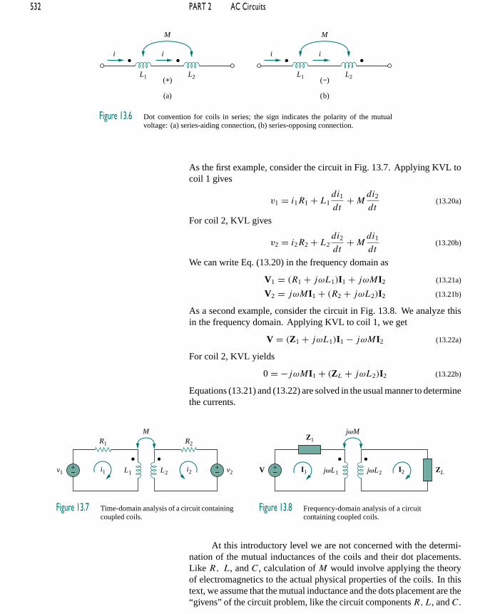
Figure 13.6 Dot convention for coils in series; the sign indicates the polarity of the mutualvoltage: (a) series-aiding connection, (b) series-opposing connection.
As the first example, consider the circuit in Fig. 13.7. Applying KVL tocoil 1 gives
v1 = i1R1 + L1di1
dt+M
di2
dt(13.20a)
For coil 2, KVL gives
v2 = i2R2 + L2di2
dt+M
di1
dt(13.20b)
We can write Eq. (13.20) in the frequency domain as
V1 = (R1 + jωL1)I1 + jωMI2 (13.21a)
V2 = jωMI1 + (R2 + jωL2)I2 (13.21b)
As a second example, consider the circuit in Fig. 13.8. We analyze thisin the frequency domain. Applying KVL to coil 1, we get
V = (Z1 + jωL1)I1 − jωMI2 (13.22a)
For coil 2, KVL yields
0 = −jωMI1 + (ZL + jωL2)I2 (13.22b)
Equations (13.21) and (13.22) are solved in the usual manner to determinethe currents.
v1 v2
R1 R2
+− L1 L2i1 i2
M
+−
Figure 13.7 Time-domain analysis of a circuit containingcoupled coils.
V ZL
Z1
+− jvL1 jvL2I1 I2
jvM
Figure 13.8 Frequency-domain analysis of a circuitcontaining coupled coils.
At this introductory level we are not concerned with the determi-nation of the mutual inductances of the coils and their dot placements.Like R, L, and C, calculation of M would involve applying the theoryof electromagnetics to the actual physical properties of the coils. In thistext, we assume that the mutual inductance and the dots placement are the“givens” of the circuit problem, like the circuit components R,L, and C.

CHAPTER 13 Magnetically Coupled Circuits 533
E X A M P L E 1 3 . 1
Calculate the phasor currents I1 and I2 in the circuit of Fig. 13.9.
V 12 Ω
−j4 Ω
+− j5 Ω j6 ΩI1 I2
j3 Ω
12 0°
Figure 13.9 For Example 13.1.
Solution:
For coil 1, KVL gives
−12 + (−j4 + j5)I1 − j3I2 = 0
or
jI1 − j3I2 = 12 (13.1.1)
For coil 2, KVL gives
−j3I1 + (12 + j6)I2 = 0
or
I1 = (12 + j6)I2
j3= (2 − j4)I2 (13.1.2)
Substituting this in Eq. (13.1.1), we get
(j2 + 4 − j3)I2 = (4 − j)I2 = 12
or
I2 = 12
4 − j= 2.91 14.04 A (13.1.3)
From Eqs. (13.1.2) and (13.1.3),
I1 = (2 − j4)I2 = (4.472 − 63.43)(2.91 14.04)
= 13.01 − 49.39 A
P R A C T I C E P R O B L E M 1 3 . 1
Determine the voltage Vo in the circuit of Fig. 13.10.
V 10 Ω
4 Ω
+− j8 Ω j5 ΩI1 I2
j1 Ω
Vo
+
−6 90°
Figure 13.10 For Practice Prob. 13.1.
Answer: 0.6 − 90 V.

534 PART 2 AC Circuits
E X A M P L E 1 3 . 2
Calculate the mesh currents in the circuit of Fig. 13.11.
V 5 Ω
4 Ω j8 Ω
+− j6 Ω
j2 Ω
I1I2
−j3 Ω
100 0°
Figure 13.11 For Example 13.2.
Solution:
The key to analyzing a magnetically coupled circuit is knowing the po-larity of the mutual voltage. We need to apply the dot rule. In Fig. 13.11,suppose coil 1 is the one whose reactance is 6 , and coil 2 is the onewhose reactance is 8 . To figure out the polarity of the mutual voltagein coil 1 due to current I2, we observe that I2 leaves the dotted terminal ofcoil 2. Since we are applying KVL in the clockwise direction, it impliesthat the mutual voltage is negative, that is, −j2I2.
+
−
j2I2
V1
(a) V1 = –2jI2
I1 j6 Ω j8 Ω
Coil 1 Coil 2
−
+
j2 ΩI1
V2
(b) V2 = –2jI1
I2j6 Ω j8 Ω
Coil 1 Coil 2
Figure 13.12 For Example 13.2;redrawing the relevant portion of thecircuit in Fig. 13.11 to find mutualvoltages by the dot convention.
Alternatively, it might be best to figure out the mutual voltage byredrawing the relevant portion of the circuit, as shown in Fig. 13.12(a),where it becomes clear that the mutual voltage is V1 = −2jI2.
Thus, for mesh 1 in Fig. 13.11, KVL gives
−100 + I1(4 − j3 + j6)− j6I2 − j2I2 = 0
or
100 = (4 + j3)I1 − j8I2 (13.2.1)
Similarly, to figure out the mutual voltage in coil 2 due to current I1,consider the relevant portion of the circuit, as shown in Fig. 13.12(b).Applying the dot convention gives the mutual voltage as V2 = −2jI1.Also, current I2 sees the two coupled coils in series in Fig. 13.11; since itleaves the dotted terminals in both coils, Eq. (13.18) applies. Therefore,for mesh 2, KVL gives
0 = −2jI1 − j6I1 + (j6 + j8 + j2 × 2 + 5)I2
or
0 = −j8I1 + (5 + j18)I2 (13.2.2)
Putting Eqs. (13.2.1) and (13.2.2) in matrix form, we get[100
0
]=
[4 + j3−j8
−j85 + j18
] [I1
I2
]

CHAPTER 13 Magnetically Coupled Circuits 535
The determinants are
=∣∣∣∣4 + j3 −j8
−j8 5 + j18
∣∣∣∣ = 30 + j87
1 =∣∣∣∣100 −j8
0 5 + j18
∣∣∣∣ = 100(5 + j18)
2 =∣∣∣∣4 + j3 100
−j8 0
∣∣∣∣ = j800
Thus, we obtain the mesh currents as
I1 = 1
= 100(5 + j18)
30 + j87= 1868.2 74.5
92.03 71= 20.3 3.5 A
I2 = 2
= j800
30 + j87= 800 90
92.03 71= 8.693 19 A
P R A C T I C E P R O B L E M 1 3 . 2
Determine the phasor currents I1 and I2 in the circuit of Fig. 13.13.
V
5 Ω j2 Ω
+− j6 Ω
j3 ΩI1 I2 −j4 Ω12 60°
Figure 13.13 For Practice Prob. 13.2.
Answer: 2.15 86.56, 3.23 86.56 A.
13.3 ENERGY IN A COUPLED CIRCUITIn Chapter 6, we saw that the energy stored in an inductor is given by
w = 1
2Li2 (13.23)
We now want to determine the energy stored in magnetically coupledcoils.
+
−
Mi1
v1
+
−
v2
i2
L1 L2
Figure 13.14 The circuitfor deriving energy stored ina coupled circuit.
Consider the circuit in Fig. 13.14. We assume that currents i1 andi2 are zero initially, so that the energy stored in the coils is zero. If we leti1 increase from zero to I1 while maintaining i2 = 0, the power in coil 1is
p1(t) = v1i1 = i1L1di1
dt(13.24)
and the energy stored in the circuit is
w1 =∫p1 dt = L1
∫ I1
0i1 di1 = 1
2L1I
21 (13.25)

536 PART 2 AC Circuits
If we now maintain i1 = I1 and increase i2 from zero to I2, the mutualvoltage induced in coil 1 isM12 di2/dt , while the mutual voltage inducedin coil 2 is zero, since i1 does not change. The power in the coils is now
p2(t) = i1M12di2
dt+ i2v2 = I1M12
di2
dt+ i2L2
di2
dt(13.26)
and the energy stored in the circuit is
w2 =∫p2 dt = M12I1
∫ I2
0di2 + L2
∫ I2
0i2 di2
= M12I1I2 + 1
2L2I
22
(13.27)
The total energy stored in the coils when both i1 and i2 have reachedconstant values is
w = w1 + w2 = 1
2L1I
21 + 1
2L2I
22 +M12I1I2 (13.28)
If we reverse the order by which the currents reach their final values, thatis, if we first increase i2 from zero to I2 and later increase i1 from zero toI1, the total energy stored in the coils is
w = 1
2L1I
21 + 1
2L2I
22 +M21I1I2 (13.29)
Since the total energy stored should be the same regardless of how wereach the final conditions, comparing Eqs. (13.28) and (13.29) leads usto conclude that
M12 = M21 = M (13.30a)
and
w = 1
2L1I
21 + 1
2L2I
22 +MI1I2 (13.30b)
This equation was derived based on the assumption that the coil currentsboth entered the dotted terminals. If one current enters one dotted terminalwhile the other current leaves the other dotted terminal, the mutual voltageis negative, so that the mutual energyMI1I2 is also negative. In that case,
w = 1
2L1I
21 + 1
2L2I
22 −MI1I2 (13.31)
Also, since I1 and I2 are arbitrary values, they may be replaced by i1 andi2, which gives the instantaneous energy stored in the circuit the generalexpression
w = 1
2L1i
21 + 1
2L2i
22 ±Mi1i2 (13.32)
The positive sign is selected for the mutual term if both currents enteror leave the dotted terminals of the coils; the negative sign is selectedotherwise.
We will now establish an upper limit for the mutual inductanceM .The energy stored in the circuit cannot be negative because the circuit is

CHAPTER 13 Magnetically Coupled Circuits 537
passive. This means that the quantity 1/2L1i21 + 1/2L2i
22 −Mi1i2 must
be greater than or equal to zero,
1
2L1i
21 + 1
2L2i
22 −Mi1i2 ≥ 0 (13.33)
To complete the square, we both add and subtract the term i1i2√L1L2 on
the right-hand side of Eq. (13.33) and obtain
1
2(i1
√L1 − i2
√L2)
2 + i1i2(√L1L2 −M) ≥ 0 (13.34)
The squared term is never negative; at its least it is zero. Therefore, thesecond term on the right-hand side of Eq. (13.34) must be greater thanzero; that is, √
L1L2 −M ≥ 0
or
M ≤√L1L2 (13.35)
Thus, the mutual inductance cannot be greater than the geometric meanof the self-inductances of the coils. The extent to which the mutualinductance M approaches the upper limit is specified by the coefficientof coupling k, given by
k = M√L1L2
(13.36)
or
M = k√L1L2 (13.37)
where 0 ≤ k ≤ 1 or equivalently 0 ≤ M ≤ √L1L2. The coupling
coefficient is the fraction of the total flux emanating from one coil thatlinks the other coil. For example, in Fig. 13.2,
k = φ12
φ1= φ12
φ11 + φ12(13.38)
and in Fig. 13.3,
k = φ21
φ2= φ21
φ21 + φ22(13.39)
If the entire flux produced by one coil links another coil, then k = 1and we have 100 percent coupling, or the coils are said to be perfectlycoupled. Thus,
The coupling coefficient k is a measure of the magneticcoupling between two coils; 0 ≤ k ≤ 1.
For k < 0.5, coils are said to be loosely coupled; and for k > 0.5, theyare said to be tightly coupled.
(a) (b)
Air or ferrite core
Figure 13.15 Windings: (a) loosely coupled,(b) tightly coupled; cutaway view demonstratesboth windings.
We expect k to depend on the closeness of the two coils, their core,their orientation, and their windings. Figure 13.15 shows loosely coupled

538 PART 2 AC Circuits
windings and tightly coupled windings. The air-core transformers usedin radio frequency circuits are loosely coupled, whereas iron-core trans-formers used in power systems are tightly coupled. The linear transform-ers discussed in Section 3.4 are mostly air-core; the ideal transformersdiscussed in Sections 13.5 and 13.6 are principally iron-core.
E X A M P L E 1 3 . 3
Consider the circuit in Fig. 13.16. Determine the coupling coefficient.Calculate the energy stored in the coupled inductors at time t = 1 s ifv = 60 cos(4t + 30) V.
v
10 Ω
+− 5 H 4 H
2.5 H
F116
Figure 13.16 For Example 13.3.
Solution:
The coupling coefficient is
k = M√L1L2
= 2.5√20
= 0.56
indicating that the inductors are tightly coupled. To find the energy stored,we need to obtain the frequency-domain equivalent of the circuit.
60 cos(4t + 30) ⇒ 60 30, ω = 4 rad/s
5 H ⇒ jωL1 = j20
2.5 H ⇒ jωM = j10
4 H ⇒ jωL2 = j16
1
16F ⇒ 1
jωC= −j4
The frequency-domain equivalent is shown in Fig. 13.17. We now applymesh analysis. For mesh 1,
(10 + j20)I1 + j10I2 = 60 30 (13.3.1)
For mesh 2,
j10I1 + (j16 − j4)I2 = 0
or
I1 = −1.2I2 (13.3.2)
Substituting this into Eq. (13.3.1) yields
I2(−12 − j14) = 60 30 ⇒ I2 = 3.254 − 160.6 A
and
I1 = −1.2I2 = 3.905 − 19.4 A
In the time-domain,
i1 = 3.905 cos(4t − 19.4), i2 = 3.254 cos(4t − 199.4)
At time t = 1 s, 4t = 4 rad = 229.2, and
i1 = 3.905 cos(229.2 − 19.4) = −3.389 A
i2 = 3.254 cos(229.2 + 160.6) = 2.824 A
CHAPTER 13 Magnetically Coupled Circuits 539
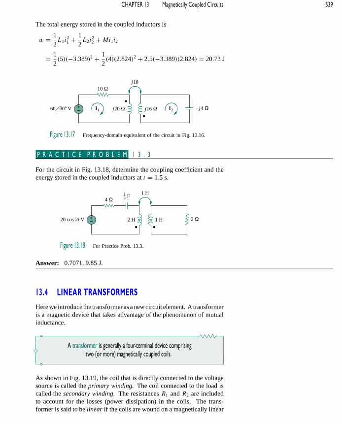
The total energy stored in the coupled inductors is
w = 1
2L1i
21 + 1
2L2i
22 +Mi1i2
= 1
2(5)(−3.389)2 + 1
2(4)(2.824)2 + 2.5(−3.389)(2.824) = 20.73 J
V
10 Ω
+− j20 Ω j16 ΩI1 I2
j10
−j4 Ω60 30°
Figure 13.17 Frequency-domain equivalent of the circuit in Fig. 13.16.
P R A C T I C E P R O B L E M 1 3 . 3
For the circuit in Fig. 13.18, determine the coupling coefficient and theenergy stored in the coupled inductors at t = 1.5 s.
20 cos 2t V
4 Ω
+− 2 H 1 H
1 H
2 Ω
F18
Figure 13.18 For Practice Prob. 13.3.
Answer: 0.7071, 9.85 J.
13.4 LINEAR TRANSFORMERSHere we introduce the transformer as a new circuit element. A transformeris a magnetic device that takes advantage of the phenomenon of mutualinductance.
A transformer is generally a four-terminal device comprisingtwo (or more) magnetically coupled coils.
As shown in Fig. 13.19, the coil that is directly connected to the voltagesource is called the primary winding. The coil connected to the load iscalled the secondary winding. The resistances R1 and R2 are includedto account for the losses (power dissipation) in the coils. The trans-former is said to be linear if the coils are wound on a magnetically linear

540 PART 2 AC Circuits
material—a material for which the magnetic permeability is constant.Such materials include air, plastic, Bakelite, and wood. In fact, most ma-terials are magnetically linear. Linear transformers are sometimes calledair-core transformers, although not all of them are necessarily air-core.They are used in radio and TV sets. Figure 13.20 portrays different typesof transformers.
A linear transformer may also be regarded as onewhose flux is proportional to the currents in itswindings.
V ZL+− L1 L2I1 I2
MR1 R2
Primary coil Secondary coil
Figure 13.19 A linear transformer.
(b)(a)
Figure 13.20 Different types of transformers: (a) copper wound dry power transformer, (b) audio transformers.(Courtesy of: (a) Electric Service Co., (b) Jensen Transformers.)
We would like to obtain the input impedance Zin as seen from thesource, because Zin governs the behavior of the primary circuit. ApplyingKVL to the two meshes in Fig. 13.19 gives
V = (R1 + jωL1)I1 − jωMI2 (13.40a)
0 = −jωMI1 + (R2 + jωL2 + ZL)I2 (13.40b)

CHAPTER 13 Magnetically Coupled Circuits 541
In Eq. (13.40b), we express I2 in terms of I1 and substitute it into Eq.(13.40a). We get the input impedance as
Zin = VI1
= R1 + jωL1 + ω2M2
R2 + jωL2 + ZL
(13.41)
Notice that the input impedance comprises two terms. The first term,(R1 + jωL1), is the primary impedance. The second term is due to thecoupling between the primary and secondary windings. It is as though thisimpedance is reflected to the primary. Thus, it is known as the reflectedimpedance ZR , and
ZR = ω2M2
R2 + jωL2 + ZL
(13.42)
It should be noted that the result in Eq. (13.41) or (13.42) is not affectedby the location of the dots on the transformer, because the same result isproduced when M is replaced by −M .
Some authors call this the coupled impedance.
The little bit of experience gained in Sections 13.2 and 13.3 inanalyzing magnetically coupled circuits is enough to convince anyone thatanalyzing these circuits is not as easy as circuits in previous chapters. Forthis reason, it is sometimes convenient to replace a magnetically coupledcircuit by an equivalent circuit with no magnetic coupling. We want toreplace the linear transformer in Fig. 13.19 by an equivalent T or circuit,a circuit that would have no mutual inductance. Ignore the resistances ofthe coils and assume that the coils have a common ground as shown inFig. 13.21. The assumption of a common ground for the two coils is amajor restriction of the equivalent circuits. A common ground is imposedon the linear transformer in Fig. 13.21 in view of the necessity of havinga common ground in the equivalent T or circuit; see Figs. 13.22 and13.23.
+
−
MI1
V1
+
−
V2
I2
L1 L2
Figure 13.21 Determiningthe equivalent circuit of alinear transformer.
+
−
I1
V1
+
−V2
I2
Lc
La Lb
Figure 13.22 An equivalent T circuit.
+
−
I1
V1
+
−V2
I2
LBLA
LC
Figure 13.23 An equivalent circuit.
The voltage-current relationships for the primary and secondarycoils give the matrix equation[
V1
V2
]=
[jωL1 jωM
jωM jωL2
] [I1
I2
](13.43)
By matrix inversion, this can be written as
[I1
I2
]=
L2
jω(L1L2 −M2)
−Mjω(L1L2 −M2)
−Mjω(L1L2 −M2)
L1
jω(L1L2 −M2)
[V1
V2
](13.44)
Our goal is to match Eqs. (13.43) and (13.44) with the correspondingequations for the T and networks.
For the T (or Y) network of Fig. 13.22, mesh analysis provides theterminal equations as[
V1
V2
]=
[jω(La + Lc) jωLc
jωLc jω(Lb + Lc)
] [I1
I2
](13.45)
If the circuits in Figs. 13.21 and 13.22 are equivalents, Eqs. (13.43) and(13.45) must be identical. Equating terms in the impedance matrices of

542 PART 2 AC Circuits
Eqs. (13.43) and (13.45) leads to
La = L1 −M, Lb = L2 −M, Lc = M (13.46)
For the (or ) network in Fig. 13.23, nodal analysis gives theterminal equations as
[I1
I2
]=
1
jωLA+ 1
jωLC− 1
jωLC
− 1
jωLC
1
jωLB+ 1
jωLC
[V1
V2
](13.47)
Equating terms in admittance matrices of Eqs. (13.44) and (13.47), weobtain
LA = L1L2 −M2
L2 −M, LB = L1L2 −M2
L1 −M
LC = L1L2 −M2
M
(13.48)
Note that in Figs. 13.23 and 13.24, the inductors are not magneticallycoupled. Also note that changing the locations of the dots in Fig. 13.21can cause M to become −M . As Example 13.6 illustrates, a negativevalue of M is physically unrealizable but the equivalent model is stillmathematically valid.
ZL+− j20 Ω j40 ΩI1 I2
j5 ΩZ1 Z2
V50 60°
Figure 13.24 For Example 13.4.
E X A M P L E 1 3 . 4
In the circuit of Fig. 13.24, calculate the input impedance and current I1.Take Z1 = 60 − j100 , Z2 = 30 + j40 , and ZL = 80 + j60 .
Solution:
From Eq. (13.41),
Zin = Z1 + j20 + (5)2
j40 + Z2 + ZL
= 60 − j100 + j20 + 25
110 + j140
= 60 − j80 + 0.14 − 51.84
= 60.09 − j80.11 = 100.14 − 53.1

CHAPTER 13 Magnetically Coupled Circuits 543
Thus,
I1 = VZin
= 50 60
100.14 − 53.1= 0.5 113.1 A
P R A C T I C E P R O B L E M 1 3 . 4
Find the input impedance of the circuit of Fig. 13.25 and the current fromthe voltage source.
4 Ω
+− j8 Ω j10 Ω
j3 Ω
j4 Ω
6 Ω
−j6 Ω
V10 0°
Figure 13.25 For Practice Prob. 13.4.
Answer: 8.58 58.05 , 1.165 − 58.05 A.
E X A M P L E 1 3 . 5
Determine the T-equivalent circuit of the linear transformer in Fig. 13.26(a).
2 H
(a)
10 H 4 H
a
b
c
d
(b)
a
b
c
d
2 H
8 H 2 H
Figure 13.26 For Example 13.5: (a) a linear transformer,(b) its T-equivalent circuit.
Solution:
Given that L1 = 10, L2 = 4, and M = 2, the T equivalent network hasthe following parameters:
La = L1 −M = 10 − 2 = 8 H
Lb = L2 −M = 4 − 2 = 2 H, Lc = M = 2 H
The T-equivalent circuit is shown in Fig. 13.26(b). We have assumed thatreference directions for currents and voltage polarities in the primary andsecondary windings conform to those in Fig. 13.21. Otherwise, we mayneed to replace M with −M , as Example 13.6 illustrates.

544 PART 2 AC Circuits
P R A C T I C E P R O B L E M 1 3 . 5
For the linear transformer in Fig. 13.26 (a), find the equivalent network.
Answer: LA = 18 H, LB = 4.5 H, LC = 18 H.
E X A M P L E 1 3 . 6
Solve for I1, I2, and Vo in Fig. 13.27 (the same circuit as for Practice Prob.13.1) using the T-equivalent circuit for the linear transformer.
+− j8 Ω j5 ΩI1 I2
j1 Ω4 Ω
V60 90° 10 Ω+
−Vo
Figure 13.27 For Example 13.6.
Solution:
Notice that the circuit in Fig. 13.27 is the same as that in Fig. 13.10 exceptthat the reference direction for current I2 has been reversed, just to makethe reference directions for the currents for the magnetically coupled coilsconform with those in Fig. 13.21.
+
−
j1 Ω
(a)
(b)
V1
+
−
V2j8 Ω j5 Ω
j9 Ω j6 Ω
−j1 Ω
I1 I2
Figure 13.28 For Example 13.6:(a) circuit for coupled coils of Fig.13.27, (b) T-equivalent circuit.
We need to replace the magnetically coupled coils with the T-equivalent circuit. The relevant portion of the circuit in Fig. 13.27 isshown in Fig. 13.28(a). Comparing Fig. 13.28(a) with Fig. 13.21 showsthat there are two differences. First, due to the current reference direc-tions and voltage polarities, we need to replace M by −M to make Fig.13.28(a) conform with Fig. 13.21. Second, the circuit in Fig. 13.21 is inthe time-domain, whereas the circuit in Fig. 13.28(a) is in the frequency-domain. The difference is the factor jω; that is, L in Fig. 13.21 has beenreplaced with jωL and M with jωM . Since ω is not specified, we canassume ω = 1 or any other value; it really does not matter. With thesetwo differences in mind,
La = L1 − (−M) = 8 + 1 = 9 H
Lb = L2 − (−M) = 5 + 1 = 6 H, Lc = −M = −1 H
Thus, the T-equivalent circuit for the coupled coils is as shown in Fig.13.28(b).
Inserting the T-equivalent circuit in Fig. 13.28(b) to replace the twocoils in Fig. 13.27 gives the equivalent circuit in Fig. 13.29, which can besolved using nodal or mesh analysis. Applying mesh analysis, we obtain
j6 = I1(4 + j9 − j1)+ I2(−j1) (13.6.1)
and0 = I1(−j1)+ I2(10 + j6 − j1) (13.6.2)
From Eq. (13.6.2),
I1 = (10 + j5)
jI2 = (5 − j10)I2 (13.6.3)

CHAPTER 13 Magnetically Coupled Circuits 545
Substituting Eq. (13.6.3) into Eq. (13.6.1) gives
j6 = (4 + j8)(5 − j10)I2 − jI2 = (100 − j)I2 100I2
Since 100 is very large compared to 1, the imaginary part of (100 − j)
can be ignored so that 100 − j 100. Hence,
I2 = j6
100= j0.06 = 0.06 90 A
From Eq. (13.6.3),
I1 = (5 − j10)j0.06 = 0.6 + j0.3 A
and
Vo = −10I2 = −j0.6 = 0.6 − 90 V
This agrees with the answer to Practice Prob. 13.1. Of course, the direc-tion of I2 in Fig. 13.10 is opposite to that in Fig. 13.27. This will notaffect Vo, but the value of I2 in this example is the negative of that of I2
in Practice Prob. 13.1. The advantage of using the T-equivalent modelfor the magnetically coupled coils is that in Fig. 13.29 we do not need tobother with the dot on the coupled coils.
j6 V
4 Ω j9 Ω
+− −j1 ΩI1 I2
j6 Ω
10 Ω
I1 I2
+
−Vo
Figure 13.29 For Example 13.6.
P R A C T I C E P R O B L E M 1 3 . 6
Solve the problem in Example 13.1 (see Fig. 13.9) using the T-equivalentmodel for the magnetically coupled coils.
Answer: 13 − 49.4 A, 2.91 14.04 A.
13.5 IDEAL TRANSFORMERSAn ideal transformer is one with perfect coupling (k = 1). It consists oftwo (or more) coils with a large number of turns wound on a commoncore of high permeability. Because of this high permeability of the core,the flux links all the turns of both coils, thereby resulting in a perfectcoupling.
To see how an ideal transformer is the limiting case of two cou-pled inductors where the inductances approach infinity and the couplingis perfect, let us reexamine the circuit in Fig. 13.14. In the frequencydomain,
V1 = jωL1I1 + jωMI2 (13.49a)
V2 = jωMI1 + jωL2I2 (13.49b)
546 PART 2 AC Circuits
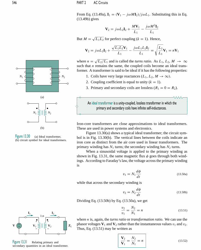
From Eq. (13.49a), I1 = (V1 − jωMI2)/jωL1. Substituting this in Eq.(13.49b) gives
V2 = jωL2I2 + MV1
L1− jωM2I2
L1
But M = √L1L2 for perfect coupling (k = 1). Hence,
V2 = jωL2I2 +√L1L2V1
L1− jωL1L2I2
L1=
√L2
L1V1 = nV1
where n = √L2/L1 and is called the turns ratio. As L1, L2, M → ∞
such that n remains the same, the coupled coils become an ideal trans-former. A transformer is said to be ideal if it has the following properties:
1. Coils have very large reactances (L1, L2, M → ∞).
2. Coupling coefficient is equal to unity (k = 1).
3. Primary and secondary coils are lossless (R1 = 0 = R2).
An ideal transformer is a unity-coupled, lossless transformer in which theprimary and secondary coils have infinite self-inductances.
Iron-core transformers are close approximations to ideal transformers.These are used in power systems and electronics.
Figure 13.30(a) shows a typical ideal transformer; the circuit sym-bol is in Fig. 13.30(b). The vertical lines between the coils indicate aniron core as distinct from the air core used in linear transformers. Theprimary winding has N1 turns; the secondary winding has N2 turns.
N1 N2
(a)
(b)
N1 N2
Figure 13.30 (a) Ideal transformer,(b) circuit symbol for ideal transformers.
ZL+− V1 V2
1:n
V+
−
+
−
I1 I2
Figure 13.31 Relating primary andsecondary quantities in an ideal transformer.
When a sinusoidal voltage is applied to the primary winding asshown in Fig. 13.31, the same magnetic flux φ goes through both wind-ings. According to Faraday’s law, the voltage across the primary windingis
v1 = N1dφ
dt(13.50a)
while that across the secondary winding is
v2 = N2dφ
dt(13.50b)
Dividing Eq. (13.50b) by Eq. (13.50a), we get
v2
v1= N2
N1= n (13.51)
where n is, again, the turns ratio or transformation ratio. We can use thephasor voltages V1 and V2 rather than the instantaneous values v1 and v2.Thus, Eq. (13.51) may be written as
V2
V1= N2
N1= n (13.52)

CHAPTER 13 Magnetically Coupled Circuits 547
For the reason of power conservation, the energy supplied to the primarymust equal the energy absorbed by the secondary, since there are no lossesin an ideal transformer. This implies that
v1i1 = v2i2 (13.53)
In phasor form, Eq. (13.53) in conjunction with Eq. (13.52) becomesI1
I2= V2
V1= n (13.54)
showing that the primary and secondary currents are related to the turnsratio in the inverse manner as the voltages. Thus,
I2
I1= N1
N2= 1
n(13.55)
When n = 1, we generally call the transformer an isolation transformer.The reason will become obvious in Section 13.9.1. If n > 1, we havea step-up transformer, as the voltage is increased from primary to sec-ondary (V2 > V1). On the other hand, if n < 1, the transformer is astep-down transformer, since the voltage is decreased from primary tosecondary (V2 < V1).
A step-down transformer is one whose secondary voltageis less than its primary voltage.
A step-up transformer is one whose secondary voltageis greater than its primary voltage.
The ratings of transformers are usually specified asV1/V2. A transformerwith rating 2400/120 V should have 2400 V on the primary and 120 in thesecondary (i.e., a step-down transformer). Keep in mind that the voltageratings are in rms.
Power companies often generate at some convenient voltage anduse a step-up transformer to increase the voltage so that the power can betransmitted at very high voltage and low current over transmission lines,resulting in significant cost savings. Near residential consumer premises,step-down transformers are used to bring the voltage down to 120 V.Section 13.9.3 will elaborate on this.
It is important that we know how to get the proper polarity of thevoltages and the direction of the currents for the transformer in Fig. 13.31.If the polarity of V1 or V2 or the direction of I1 or I2 is changed, n in Eqs.(13.51) to (13.55) may need to be replaced by −n. The two simple rulesto follow are:
1. If V1 and V2 are both positive or both negative at the dottedterminals, use +n in Eq. (13.52). Otherwise, use −n.
2. If I1 and I2 both enter into or both leave the dotted terminals,use −n in Eq. (13.55). Otherwise, use +n.
The rules are demonstrated with the four circuits in Fig. 13.32.
V1 V2
N1:N2
+
−
+
−
I1 I2
V2
V1
N2
N1=
I2
I1
N1
N2=
(a)
V1 V2
N1:N2
+
−
+
−
I1 I2
V2
V1
N2
N1=
I2
I1
N1
N2= −
(b)
V1 V2
N1:N2
+
−
+
−
I1
I2
V2
V1
N2
N1= −
V2
V1
N2
N1= −
I2
I1
N1
N2=
(c)
V1 V2
N1:N2
+
−
+
−
I1
I2
I2
I1
N1
N2= −
(d)
Figure 13.32 Typicalcircuits illustrating propervoltage polarities andcurrent directions in anideal transformer.

548 PART 2 AC Circuits
Using Eqs. (13.52) and (13.55), we can always express V1 in termsof V2 and I1 in terms of I2, or vice versa:
V1 = V2
nor V2 = nV1 (13.56)
I1 = nI2 or I2 = I1
n(13.57)
The complex power in the primary winding is
S1 = V1I∗1 = V2
n(nI2)
∗ = V2I∗2 = S2 (13.58)
showing that the complex power supplied to the primary is delivered to thesecondary without loss. The transformer absorbs no power. Of course,we should expect this, since the ideal transformer is lossless. The inputimpedance as seen by the source in Fig. 13.31 is found from Eqs. (13.56)and (13.57) as
Zin = V1
I1= 1
n2
V2
I2(13.59)
It is evident from Fig. 13.31 that V2/I2 = ZL, so that
Zin = ZL
n2(13.60)
The input impedance is also called the reflected impedance, since it ap-pears as if the load impedance is reflected to the primary side. This abilityof the transformer to transform a given impedance into another impedanceprovides us a means of impedance matching to ensure maximum powertransfer. The idea of impedance matching is very useful in practice andwill be discussed more in Section 13.9.2.
Notice that an ideal transformer reflects an im-pedance as the square of the turns ratio.
In analyzing a circuit containing an ideal transformer, it is commonpractice to eliminate the transformer by reflecting impedances and sourcesfrom one side of the transformer to the other. In the circuit of Fig. 13.33,suppose we want to reflect the secondary side of the circuit to the primaryside. We find the Thevenin equivalent of the circuit to the right of theterminals a-b. We obtain VTh as the open-circuit voltage at terminals a-b,as shown in Fig. 13.34(a). Since terminals a-b are open, I1 = 0 = I2 sothat V2 = Vs2. Hence, from Eq. (13.56),
VTh = V1 = V2
n= Vs2
n(13.61)
+−
Z1 Z2
Vs1+− Vs2
I1 I2a
b
c
d
V1 V2
+
−
+
−
1:n
Figure 13.33 Ideal transformer circuit whose equivalent circuits areto be found.

CHAPTER 13 Magnetically Coupled Circuits 549
Z2
+− Vs2
I1 I2a
b
a
b
V1VTh V2
+
−
+
−
1:n
(a)
+−
I1 I2
V1 V2
+
−
+
−
1:n
(b)
+
−
Z2V1 0°
Figure 13.34 (a) Obtaining VTh for the circuit in Fig. 13.33, (b) obtaining ZTh for the circuit in Fig. 13.33.
To get ZTh, we remove the voltage source in the secondary winding andinsert a unit source at terminals a-b, as in Fig. 13.34(b). From Eqs. (13.56)and (13.57), I1 = nI2 and V1 = V2/n, so that
ZTh = V1
I1= V2/n
nI2= Z2
n2, V2 = Z2I2 (13.62)
which is what we should have expected from Eq. (13.60). Once we haveVTh and ZTh, we add the Thevenin equivalent to the part of the circuit inFig. 13.33 to the left of terminals a-b. Figure 13.35 shows the result.
+−
Z1
Vs1+−
Vs2n
a
b
V1
+
−
n2
Z2
Figure 13.35 Equivalent circuit for Fig. 13.33obtained by reflecting the secondary circuit tothe primary side.
The general rule for eliminating the transformer and reflecting the secondary circuitto the primary side is: divide the secondary impedance by n2, divide the secondary
voltage by n, and multiply the secondary current by n.
We can also reflect the primary side of the circuit in Fig. 13.33 tothe secondary side. Figure 13.36 shows the equivalent circuit.
The rule for eliminating the transformer and reflecting the primary circuit to thesecondary side is: multiply the primary impedance by n2, multiply the primary
voltage by n, and divide the primary current by n.
According to Eq. (13.58), the power remains the same, whether calculatedon the primary or the secondary side. But realize that this reflectionapproach only applies if there are no external connections between theprimary and secondary windings. When we have external connectionsbetween the primary and secondary windings, we simply use regularmesh and nodal analysis. Examples of circuits where there are externalconnections between the primary and secondary windings are in Figs.13.39 and 13.40. Also note that if the locations of the dots in Fig. 13.33are changed, we might have to replace n by −n in order to obey the dotrule, illustrated in Fig. 13.32.
+−
n2Z1 Z2
nVs1 Vs2+−
c
d
V2
+
−
Figure 13.36 Equivalent circuit for Fig. 13.33obtained by reflecting the primary circuit to thesecondary side.
E X A M P L E 1 3 . 7
An ideal transformer is rated at 2400/120 V, 9.6 kVA, and has 50 turnson the secondary side. Calculate: (a) the turns ratio, (b) the number of

550 PART 2 AC Circuits
turns on the primary side, and (c) the current ratings for the primary andsecondary windings.
Solution:
(a) This is a step-down transformer, since V1 = 2400 V > V2 = 120 V.
n = V2
V1= 120
2400= 0.05
(b)
n = N2
N1⇒ 0.05 = 50
N1or
N1 = 50
0.05= 1000 turns
(c) S = V1I1 = V2I2 = 9.6 kVA. Hence,
I1 = 9600
V1= 9600
2400= 4 A
I2 = 9600
V2= 9600
120= 80 A or I2 = I1
n= 4
0.05= 80 A
P R A C T I C E P R O B L E M 1 3 . 7
The primary current to an ideal transformer rated at 3300/110 V is 3 A.Calculate: (a) the turns ratio, (b) the kVA rating, (c) the secondary current.
Answer: (a) 1/30, (b) 9.9 kVA, (c) 90 A.
E X A M P L E 1 3 . 8
For the ideal transformer circuit of Fig. 13.37, find: (a) the source currentI1, (b) the output voltage Vo, and (c) the complex power supplied by thesource.
4 Ω
+− 20 Ω
−j6 Ω
V1 V2 Vo
1:2
+
−
+
−
I1 I2
V rms120 0°+
−
Figure 13.37 For Example 13.8.
Solution:
(a) The 20- impedance can be reflected to the primary side and we get
ZR = 20
n2= 20
4= 5
Thus,Zin = 4 − j6 + ZR = 9 − j6 = 10.82 − 33.69
I1 = 120 0
Zin= 120 0
10.82 − 33.69= 11.09 33.69 A

CHAPTER 13 Magnetically Coupled Circuits 551
(b) Since both I1 and I2 leave the dotted terminals,
I2 = −1
nI1 = −5.545 33.69 A
Vo = 20I2 = 110.9 213.69 V
(c) The complex power supplied is
S = VsI∗1 = (120 0)(11.09 − 33.69) = 1330.8 − 33.69 VA
P R A C T I C E P R O B L E M 1 3 . 8
In the ideal transformer circuit of Fig. 13.38, find Vo and the complexpower supplied by the source.
2 Ω
+−
16 Ω
V1 V2 Vo
1:4
+
−
+
−
I1 I2
V rms100 0°+
−−j24 Ω
Figure 13.38 For Practice Prob. 13.8.
Answer: 178.9 116.56 V, 2981.5 − 26.56 VA.
E X A M P L E 1 3 . 9
Calculate the power supplied to the 10- resistor in the ideal transformercircuit of Fig. 13.39.
20 Ω
10 Ω
V1 V2
2:1
+
−
+
−V rms120 0°
30 Ω
+− I1 I2
Figure 13.39 For Example 13.9.
Solution:
Reflection to the secondary or primary side cannot be done with thiscircuit: there is direct connection between the primary and secondarysides due to the 30- resistor. We apply mesh analysis. For mesh 1,
−120 + (20 + 30)I1 − 30I2 + V1 = 0
or
50I1 − 30I2 + V1 = 120 (13.9.1)

552 PART 2 AC Circuits
For mesh 2,
−V2 + (10 + 30)I2 − 30I1 = 0
or
−30I1 + 40I2 − V2 = 0 (13.9.2)
At the transformer terminals,
V2 = −1
2V1 (13.9.3)
I2 = −2I1 (13.9.4)
(Note that n = 1/2.) We now have four equations and four unknowns,but our goal is to get I2. So we substitute for V1 and I1 in terms of V2
and I2 in Eqs. (13.9.1) and (13.9.2). Equation (13.9.1) becomes
−55I2 − 2V2 = 120 (13.9.5)
and Eq. (13.9.2) becomes
15I2 + 40I2 − V2 = 0 ⇒ V2 = 55I2 (13.9.6)
Substituting Eq. (13.9.6) in Eq. (13.9.5),
−165I2 = 120 ⇒ I2 = −120
165= −0.7272 A
The power absorbed by the 10- resistor is
P = (−0.7272)2(10) = 5.3 W
P R A C T I C E P R O B L E M 1 3 . 9
Find Vo in the circuit in Fig. 13.40.
4 Ω
8 Ω
1:2
V60 0° +−
2 Ω
8 Ω
+ −Vo
Figure 13.40 For Practice Prob. 13.9.
Answer: 24 V.
13.6 IDEAL AUTOTRANSFORMERSUnlike the conventional two-winding transformer we have considered sofar, an autotransformer has a single continuous winding with a connectionpoint called a tap between the primary and secondary sides. The tap is

CHAPTER 13 Magnetically Coupled Circuits 553
often adjustable so as to provide the desired turns ratio for stepping upor stepping down the voltage. This way, a variable voltage is provided tothe load connected to the autotransformer.
An autotransformer is a transformer in which both the primaryand the secondary are in a single winding.
Figure 13.41 A typical autotransformer.(Courtesy of Todd Systems, Inc.)
Figure 13.41 shows a typical autotransformer. As shown in Fig.13.42, the autotransformer can operate in the step-down or step-up mode.The autotransformer is a type of power transformer. Its major advantageover the two-winding transformer is its ability to transfer larger apparentpower. Example 13.10 will demonstrate this. Another advantage is thatan autotransformer is smaller and lighter than an equivalent two-windingtransformer. However, since both the primary and secondary windingsare one winding, electrical isolation (no direct electrical connection) islost. (We will see how the property of electrical isolation in the conven-tional transformer is practically employed in Section 13.9.1.) The lackof electrical isolation between the primary and secondary windings is amajor disadvantage of the autotransformer.
Some of the formulas we derived for ideal transformers apply toideal autotransformers as well. For the step-down autotransformer circuitof Fig. 13.42(a), Eq. (13.52) gives
V1
V2= N1 +N2
N2= 1 + N1
N2(13.63)
As an ideal autotransformer, there are no losses, so the complex powerremains the same in the primary and secondary windings:
S1 = V1I∗1 = S2 = V2I∗
2 (13.64)
Equation (13.64) can also be expressed with rms values as
V1I1 = V2I2
or
V2
V1= I1
I2(13.65)
Thus, the current relationship is
I1
I2= N2
N1 +N2(13.66)
+−
I1
I2
V1N1
N2
+
−
V2
+
−
(a)
V
+−
I1
I2
V1
N1
N2+
−
V2
+
−
(b)
ZL
ZL
V
Figure 13.42 (a) Step-down autotransformer,(b) step-up autotransformer.
For the step-up autotransformer circuit of Fig. 13.42(b),
V1
N1= V2
N1 +N2
or
V1
V2= N1
N1 +N2(13.67)

554 PART 2 AC Circuits
The complex power given by Eq. (13.64) also applies to the step-up auto-transformer so that Eq. (13.65) again applies. Hence, the current relation-ship is
I1
I2= N1 +N2
N1= 1 + N2
N1(13.68)
A major difference between conventional transformers and auto-transformers is that the primary and secondary sides of the autotrans-former are not only coupled magnetically but also coupled conductively.The autotransformer can be used in place of a conventional transformerwhen electrical isolation is not required.
E X A M P L E 1 3 . 1 0
Compare the power ratings of the two-winding transformer in Fig.13.43(a) and the autotransformer in Fig. 13.43(b).
+
−
(a) (b)
240 V
+
−
12 VVsVp
0.2 A 4 A
4 A
+
−
Vs = 12 V+
−
Vp = 240 V+
−
+
−
+
−
240 V
+
−
252 V
4 A
0.2 A
Figure 13.43 For Example 13.10.
Solution:
Although the primary and secondary windings of the autotransformerare together as a continuous winding, they are separated in Fig. 13.43(b)for clarity. We note that the current and voltage of each winding of theautotransformer in Fig. 13.43(b) are the same as those for the two-windingtransformer in Fig. 13.43(a). This is the basis of comparing their powerratings.
For the two-winding transformer, the power rating is
S1 = 0.2(240) = 48 VA or S2 = 4(12) = 48 VA
For the autotransformer, the power rating is
S1 = 4.2(240) = 1008 VA or S2 = 4(252) = 1008 VA
which is 21 times the power rating of the two-winding transformer.
P R A C T I C E P R O B L E M 1 3 . 1 0
Refer to Fig. 13.43. If the two-winding transformer is a 60-VA,120 V/10 V transformer, what is the power rating of the autotransformer?
Answer: 780 VA.

CHAPTER 13 Magnetically Coupled Circuits 555
E X A M P L E 1 3 . 1 1
Refer to the autotransformer circuit in Fig. 13.44. Calculate: (a) I1, I2,and Io if ZL = 8+ j6, and (b) the complex power supplied to the load.
+−
I1
I2
V1
120 turns
80 turns
+
−
V2
+
−
ZL
Io
120 30° V rms
Figure 13.44 For Example 13.11.
Solution:
(a) This is a step-up autotransformer with N1 = 80, N2 = 120, V1 =120 30, so Eq. (13.67) can be used to find V2 by
V1
V2= N1
N1 +N2= 80
200
or
V2 = 200
80V1 = 200
80(120 30) = 300 30 V
I2 = V2
ZL
= 300 30
8 + j6= 300 30
10 36.87= 30 − 6.87 A
But
I1
I2= N1 +N2
N1= 200
80
or
I1 = 200
80I2 = 200
80(30 − 6.87) = 75 − 6.87 A
At the tap, KCL gives
I1 + Io = I2
or
Io = I2 − I1 = 30 − 6.87 − 75 − 6.87 = 45 173.13 A
(b) The complex power supplied to the load is
S2 = V2I∗2 = |I2|2ZL = (30)2(10 36.87) = 9 36.87 kVA

556 PART 2 AC Circuits
P R A C T I C E P R O B L E M 1 3 . 1 1
In the autotransformer circuit in Fig. 13.45, find currents I1, I2, and Io.Take V1 = 1250 V, V2 = 800 V.
I1
I2
V2
+
−
V1
+
− Io
16 kVA load
Figure 13.45 For Practice Prob. 13.11.
Answer: 12.8 A, 20 A, 7.2 A.
†13.7 THREE-PHASE TRANSFORMERSTo meet the demand for three-phase power transmission, transformerconnections compatible with three-phase operations are needed. We canachieve the transformer connections in two ways: by connecting threesingle-phase transformers, thereby forming a so-called transformer bank,or by using a special three-phase transformer. For the same kVA rat-ing, a three-phase transformer is always smaller and cheaper than threesingle-phase transformers. When single-phase transformers are used, onemust ensure that they have the same turns ratio n to achieve a balancedthree-phase system. There are four standard ways of connecting threesingle-phase transformers or a three-phase transformer for three-phaseoperations: Y-Y, -, Y-, and -Y.
For any of the four connections, the total apparent power ST , realpower PT , and reactive power QT are obtained as
ST =√
3VLIL (13.69a)
PT = ST cos θ =√
3VLIL cos θ (13.69b)
QT = ST sin θ =√
3VLIL sin θ (13.69c)
where VL and IL are, respectively, equal to the line voltage VLp and theline current ILp for the primary side, or the line voltage VLs and the linecurrent ILs for the secondary side. Notice from Eq. (13.69) that for each ofthe four connections, VLsILs = VLpILp, since power must be conservedin an ideal transformer.
For the Y-Y connection (Fig. 13.46), the line voltage VLp at theprimary side, the line voltage VLs on the secondary side, the line currentILp on the primary side, and the line current ILs on the secondary sideare related to the transformer per phase turns ratio n according to Eqs.(13.52) and (13.55) as
VLs = nVLp (13.70a)
ILs = ILp
n(13.70b)

CHAPTER 13 Magnetically Coupled Circuits 557
For the - connection (Fig. 13.47), Eq. (13.70) also applies forthe line voltages and line currents. This connection is unique in the sensethat if one of the transformers is removed for repair or maintenance, theother two form an open delta, which can provide three-phase voltages ata reduced level of the original three-phase transformer.
+
−
VLp
+
−
VLs = nVLp
ILpILs =
ILp
n1:n
Figure 13.46 Y-Y three-phase transformer connection.
+
−VLp
+
−VLs = nVLp
ILpILs =
ILp
n1:n
Figure 13.47 - three-phase transformer connection.
For the Y- connection (Fig. 13.48), there is a factor of√
3 arisingfrom the line-phase values in addition to the transformer per phase turnsratio n. Thus,
VLs = nVLp√3
(13.71a)
ILs =√
3ILpn
(13.71b)
Similarly, for the -Y connection (Fig. 13.49),
VLs = n√
3VLp (13.72a)
ILs = ILp
n√
3(13.72b)
+
−
VLp
+
−
ILp
1:n
ILs = 3 ILp
n
VLs = nVLp
3
Figure 13.48 Y- three-phase transformer connection.
+
−
VLs = n VLp
ILp 1:n
ILs = ILp
3n
3
+
−
VLp
Figure 13.49 -Y three-phase transformer connection.

558 PART 2 AC Circuits
E X A M P L E 1 3 . 1 2
The 42-kVA balanced load depicted in Fig. 13.50 is supplied by a three-phase transformer. (a) Determine the type of transformer connections.(b) Find the line voltage and current on the primary side. (c) Determinethe kVA rating of each transformer used in the transformer bank. Assumethat the transformers are ideal.
a
b
c
A
B
C
42 kVAThree-phaseload
240 V
1:5
Figure 13.50 For Example 13.12.
Solution:
(a) A careful observation of Fig. 13.50 shows that the primary side isY-connected, while the secondary side is -connected. Thus, the three-phase transformer is Y-, similar to the one shown in Fig. 13.48.(b) Given a load with total apparent power ST = 42 kVA, the turns ra-tio n = 5, and the secondary line voltage VLs = 240 V, we can find thesecondary line current using Eq. (13.69a), by
ILs = ST√3VLs
= 42,000√3(240)
= 101 A
From Eq. (13.71),
ILp = n√3ILs = 5 × 101√
3= 292 A
VLp =√
3
nVLs =
√3 × 240
5= 83.14 V
(c) Because the load is balanced, each transformer equally shares thetotal load and since there are no losses (assuming ideal transformers), thekVA rating of each transformer is S = ST /3 = 14 kVA. Alternatively,the transformer rating can be determined by the product of the phasecurrent and phase voltage of the primary or secondary side. For theprimary side, for example, we have a delta connection, so that the phasevoltage is the same as the line voltage of 240 V, while the phase currentis ILp/
√3 = 58.34 A. Hence, S = 240 × 58.34 = 14 kVA.
P R A C T I C E P R O B L E M 1 3 . 1 2
A three-phase - transformer is used to step down a line voltage of625 kV, to supply a plant operating at a line voltage of 12.5 kV. The plant
CHAPTER 13 Magnetically Coupled Circuits 559
draws 40 MW with a lagging power factor of 85 percent. Find: (a) thecurrent drawn by the plant, (b) the turns ratio, (c) the current on the primaryside of the transformer, and (d) the load carried by each transformer.
Answer: (a) 2.1736 kA, (b) 0.02, (c) 43.47 A, (d) 15.69 MVA.
13.8 PSPICE ANALYSIS OF MAGNETICALLY COUPLEDCIRCUITS
PSpice analyzes magnetically coupled circuits just like inductor circuitsexcept that the dot convention must be followed. In PSpice Schematic, thedot (not shown) is always next to pin 1, which is the left-hand terminal ofthe inductor when the inductor with part name L is placed (horizontally)without rotation on a schematic. Thus, the dot or pin 1 will be at thebottom after one 90 counterclockwise rotation, since rotation is alwaysabout pin 1. Once the magnetically coupled inductors are arranged withthe dot convention in mind and their value attributes are set in henries, weuse the coupling symbol K−LINEAR to define the coupling. For eachpair of coupled inductors, take the following steps:
1. Select Draw/Get New Part and type K−LINEAR.
2. Hit 〈enter〉 or click OK and place the K−LINEAR symbol onthe schematic, as shown in Fig. 13.51. (Notice thatK−LINEAR is not a component and therefore has no pins.)
3. DCLICKL on COUPLING and set the value of the couplingcoefficient k.
4. DCLICKL on the boxed K (the coupling symbol) and enterthe reference designator names for the coupled inductors asvalues of Li, i = 1, 2, . . . , 6. For example, if inductors L20and L23 are coupled, we set L1 = L20 and L2 = L23. L1 andat least one other Li must be assigned values; other Li’s may beleft blank.
In step 4, up to six coupled inductors with equal coupling can be specified.For the air-core transformer, the partname is XFRM−LINEAR. It
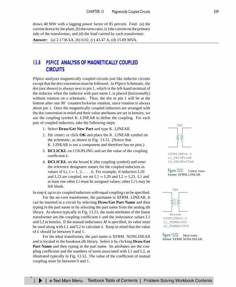
can be inserted in a circuit by selecting Draw/Get Part Name and thentyping in the part name or by selecting the part name from the analog.slblibrary. As shown typically in Fig. 13.51, the main attributes of the lineartransformer are the coupling coefficient k and the inductance values L1and L2 in henries. If the mutual inductanceM is specified, its value mustbe used along with L1 and L2 to calculate k. Keep in mind that the valueof k should lie between 0 and 1.
TX2
COUPLING=0.5L1_VALUE=1mHL2_VALUE=25mH
Figure 13.51 Linear trans-former XFRM LINEAR.
TX4
COUPLING=0.5L1_TURNS=500L2_TURNS=1000
kbreak
Figure 13.52 Ideal trans-former XFRM NONLINEAR.
For the ideal transformer, the part name is XFRM−NONLINEARand is located in the breakout.slb library. Select it by clicking Draw/GetPart Name and then typing in the part name. Its attributes are the cou-pling coefficient and the numbers of turns associated with L1 and L2, asillustrated typically in Fig. 13.52. The value of the coefficient of mutualcoupling must lie between 0 and 1.

560 PART 2 AC Circuits
PSpice has some additional transformer configurations that we willnot discuss here.
E X A M P L E 1 3 . 1 3
Use PSpice to find i1, i2, and i3 in the circuit displayed in Fig. 13.53.
40 cos 12pt V60 cos (12pt – 10°) V 4 H
2 H1.5 H
270 mF
3 H3 H
1 H
2 H
+−
+−
70 Ω
100 Ω
i2
i1 i3
Figure 13.53 For Example 13.13.
Solution:
The coupling coefficients of the three coupled inductors are determinedas follows.
k12 = M12√L1L2
= 1√3 × 3
= 0.3333
k13 = M13√L1L3
= 1.5√3 × 4
= 0.433
k23 = M23√L2L3
= 2√3 × 4
= 0.5774
The operating frequency f is obtained from Fig. 13.53 as ω = 12π =2πf → f = 6 Hz.
The right-hand values are the reference designa-tors of the inductors on the schematic.
The schematic of the circuit is portrayed in Fig. 13.54. Notice howthe dot convention is adhered to. For L2, the dot (not shown) is on pin1 (the left-hand terminal) and is therefore placed without rotation. ForL1, in order for the dot to be on the right-hand side of the inductor, theinductor must be rotated through 180. For L3, the inductor must berotated through 90 so that the dot will be at the bottom. Note that the2-H inductor (L4) is not coupled. To handle the three coupled inductors,we use three K−LINEAR parts provided in the analog library and set thefollowing attributes (by double-clicking on the symbol K in the box):
K1 - K_LINEARL1 = L1L2 = L2COUPLING = 0.3333
K2 - K_LINEARL1 = L2L2 = L3COUPLING = 0.433
CHAPTER 13 Magnetically Coupled Circuits 561
K3 - K_LINEARL1 = L1L2 = L3COUPLING = 0.5774
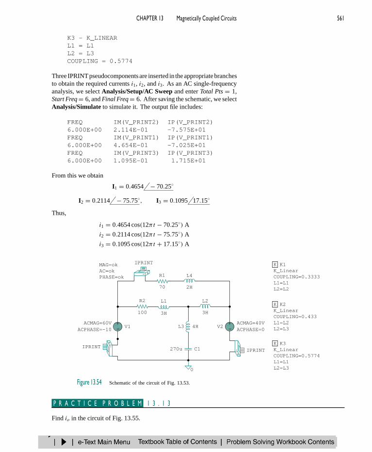
Three IPRINT pseudocomponents are inserted in the appropriate branchesto obtain the required currents i1, i2, and i3. As an AC single-frequencyanalysis, we select Analysis/Setup/AC Sweep and enter Total Pts = 1,Start Freq = 6, and Final Freq = 6. After saving the schematic, we selectAnalysis/Simulate to simulate it. The output file includes:
FREQ IM(V_PRINT2) IP(V_PRINT2)6.000E+00 2.114E-01 -7.575E+01FREQ IM(V_PRINT1) IP(V_PRINT1)6.000E+00 4.654E-01 -7.025E+01FREQ IM(V_PRINT3) IP(V_PRINT3)6.000E+00 1.095E-01 1.715E+01
From this we obtain
I1 = 0.4654 − 70.25
I2 = 0.2114 − 75.75, I3 = 0.1095 17.15
Thus,
i1 = 0.4654 cos(12πt − 70.25) A
i2 = 0.2114 cos(12πt − 75.75) A
i3 = 0.1095 cos(12πt + 17.15) A
V24HL3
270u
0
L2
3H3H
L1
L4R1
2H70
R2
100
−+ ACMAG=40V
ACPHASE=0V1−
+ACMAG=60VACPHASE=-10
MAG=okAC=okPHASE=ok
K K1K_LinearCOUPLING=0.3333L1=L1L2=L2
K K2K_LinearCOUPLING=0.433L1=L2L2=L3
K K3K_LinearCOUPLING=0.5774L1=L1L2=L3
IPRINT
IPRINTIPRINTC1
Figure 13.54 Schematic of the circuit of Fig. 13.53.
P R A C T I C E P R O B L E M 1 3 . 1 3
Find io in the circuit of Fig. 13.55.

562 PART 2 AC Circuits
20 Ω
6 H5 H 4 H8 cos (4t + 50°) V +−
10 Ω
8 Ω
12 Ωk = 0.4
25 mF
io
Figure 13.55 For Practice Prob. 13.13.
Answer: 0.1006 cos(4t + 68.52) A.
E X A M P L E 1 3 . 1 4
Find V1 and V2 in the ideal transformer circuit of Fig. 13.56 using PSpice.
80 Ω
6 ΩV1 V2
4:1
+
−
+
−V
20 Ω
+−120 30°
−j40 Ω
j10 Ω
Figure 13.56 For Example 13.14.
Solution:
As usual, we assume ω = 1 and find the corresponding values of capac-itance and inductance of the elements:
j10 = jωL ⇒ L = 10 H
−j40 = 1
jωC⇒ C = 25 mF
Figure 13.57 shows the schematic. For the ideal transformer, we setthe coupling factor to 0.999 and the numbers of turns to 400,000 and100,000. The two VPRINT2 pseudocomponents are connected acrossthe transformer terminals to obtain V1 and V2. As a single-frequencyanalysis, we select Analysis/Setup/AC Sweep and enter Total Pts =1, Start Freq = 0.1592, and Final Freq = 0.1592. After saving theschematic, we select Analysis/Simulate to simulate it. The output fileincludes:
Reminder: For an ideal transformer, the induc-tances of both the primary and secondary wind-ings are infinitely large.
FREQ VM(C,A) VP(C,A)1.592E-01 1.212E+02 -1.435E+02

CHAPTER 13 Magnetically Coupled Circuits 563
FREQ VM(B,C) VP(B,C)1.592E-01 2.775E+02 2.789E+01
From this we obtain
V1 = −V(C,A) = 121.1 36.5 V
V2 = V(B,C) = 27.75 27.89 V
R1
V1
80
6R3
10HL1
TX1
ACMAG=120VACPHASE=30
AC=okMAG=okPHASE=ok
AC=okMAG=okPHASE=ok
L1_TURNS=400000L2_TURNS=100000COUPLING=0.999
20R2
C1A B
C
25m
−+
0
kbreak
Figure 13.57 The schematic for the circuit in Fig. 13.56.
P R A C T I C E P R O B L E M 1 3 . 1 4
Obtain V1 and V2 in the circuit of Fig. 13.58 using PSpice.
10 Ω2:3
30 Ω
20 Ω
V1 V2
+
−
+
−V +
−100 20° −j16 Ω
j15 Ω
Figure 13.58 For Practice Prob. 13.14.
Answer: 63.1 28.65 V, 94.64 − 151.4 V.
†13.9 APPLICATIONSTransformers are the largest, the heaviest, and often the costliest of circuitcomponents. Nevertheless, they are indispensable passive devices in
564 PART 2 AC Circuits
electric circuits. They are among the most efficient machines, 95 percentefficiency being common and 99 percent being achievable. They havenumerous applications. For example, transformers are used:
• To step up or step down voltage and current, making themuseful for power transmission and distribution.
• To isolate one portion of a circuit from another (i.e., to transferpower without any electrical connection).
• As an impedance-matching device for maximum power transfer.
• In frequency-selective circuits whose operation depends on theresponse of inductances.
Because of these diverse uses, there are many special designs fortransformers (only some of which are discussed in this chapter): voltagetransformers, current transformers, power transformers, distribution trans-formers, impedance-matching transformers, audio transformers, single-phase transformers, three-phase transformers, rectifier transformers,inverter transformers, and more. In this section, we consider three im-portant applications: transformer as an isolation device, transformer as amatching device, and power distribution system.
Formore information on themany kinds of trans-formers, a good text is W. M. Flanagan, Hand-book of Transformer Design and Applications, 2nded. (New York: McGraw-Hill, 1993).
1 3 . 9 . 1 Tr an s fo rmer a s an I so l a t i on Dev i c eElectrical isolation is said to exist between two devices when there is nophysical connection between them. In a transformer, energy is transferredby magnetic coupling, without electrical connection between the primarycircuit and secondary circuit. We now consider three simple practicalexamples of how we take advantage of this property.
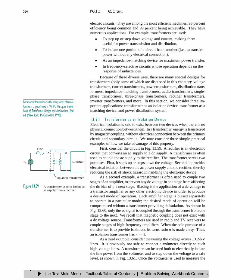
First, consider the circuit in Fig. 13.59. A rectifier is an electroniccircuit that converts an ac supply to a dc supply. A transformer is oftenused to couple the ac supply to the rectifier. The transformer serves twopurposes. First, it steps up or steps down the voltage. Second, it provideselectrical isolation between the ac power supply and the rectifier, therebyreducing the risk of shock hazard in handling the electronic device.
va+−
1:nFuse
Rectifier
Isolation transformer
Figure 13.59 A transformer used to isolate anac supply from a rectifier.
As a second example, a transformer is often used to couple twostages of an amplifier, to prevent any dc voltage in one stage from affectingthe dc bias of the next stage. Biasing is the application of a dc voltage toa transistor amplifier or any other electronic device in order to producea desired mode of operation. Each amplifier stage is biased separatelyto operate in a particular mode; the desired mode of operation will becompromised without a transformer providing dc isolation. As shown inFig. 13.60, only the ac signal is coupled through the transformer from onestage to the next. We recall that magnetic coupling does not exist witha dc voltage source. Transformers are used in radio and TV receivers tocouple stages of high-frequency amplifiers. When the sole purpose of atransformer is to provide isolation, its turns ratio n is made unity. Thus,an isolation transformer has n = 1.
As a third example, consider measuring the voltage across 13.2-kVlines. It is obviously not safe to connect a voltmeter directly to suchhigh-voltage lines. A transformer can be used both to electrically isolatethe line power from the voltmeter and to step down the voltage to a safelevel, as shown in Fig. 13.61. Once the voltmeter is used to measure the

CHAPTER 13 Magnetically Coupled Circuits 565
secondary voltage, the turns ratio is used to determine the line voltage onthe primary side.
1:1
Amplifierstage 2
Amplifierstage 1
Isolation transformer
ac onlyac + dc
Figure 13.60 A transformer providing dc isolation betweentwo amplifier stages.
1:n
V120 V
–
+
13,200 V–
+Power lines
Voltmeter
Figure 13.61 A transformer providing isolation betweenthe power lines and the voltmeter.
E X A M P L E 1 3 . 1 5
Determine the voltage across the load in Fig. 13.62.
Solution:
We can apply the superposition principle to find the load voltage. LetvL = vL1 + vL2, where vL1 is due to the dc source and vL2 is due to theac source. We consider the dc and ac sources separately, as shown inFig. 13.63. The load voltage due to the dc source is zero, because a time-varying voltage is necessary in the primary circuit to induce a voltage inthe secondary circuit. Thus, vL1 = 0. For the ac source,
V2
V1= V2
120= 1
3or V2 = 120
3= 40 V
Hence, VL2 = 40 V ac or vL2 = 40 cosωt ; that is, only the ac voltageis passed to the load by the transformer. This example shows how thetransformer provides dc isolation.
3:1
+−
120 Vac
12 Vdc
RL = 5 kΩ
Figure 13.62 For Example 13.15.
3:1
6 Vdc RLV2 = 0
3:1
+−
120 Vac RL
+
−
+
−V2V1
+
−
(a) (b)
Figure 13.63 For Example 13.15: (a) dc source, (b) ac source.
P R A C T I C E P R O B L E M 1 3 . 1 5
Refer to Fig. 13.61. Calculate the turns ratio required to step down the13.2-kV line voltage to a safe level of 120 V.
Answer: 1/110.

566 PART 2 AC Circuits
13 . 9 . 2 Tr an s fo rmer a s a Ma t ch i n g Dev i c eWe recall that for maximum power transfer, the load resistanceRL must bematched with the source resistanceRs . In most cases, the two resistancesare not matched; both are fixed and cannot be altered. However, an iron-core transformer can be used to match the load resistance to the sourceresistance. This is called impedance matching. For example, to connect aloudspeaker to an audio power amplifier requires a transformer, becausethe speaker’s resistance is only a few ohms while the internal resistanceof the amplifier is several thousand ohms.
Consider the circuit shown in Fig. 13.64. We recall from Eq. (13.60)that the ideal transformer reflects its load back to the primary with ascaling factor of n2. To match this reflected load RL/n2 with the sourceresistance Rs , we set them equal,
Rs = RL
n2(13.73)
Equation (13.73) can be satisfied by proper selection of the turns ration. From Eq. (13.73), we notice that a step-down transformer (n < 1) isneeded as the matching device when Rs > RL, and a step-up (n > 1) isrequired when Rs < RL.
vs+−
1:n
Matching transformerLoadSource
Rs
RL
Figure 13.64 Transformer used as a matchingdevice.
E X A M P L E 1 3 . 1 6
The ideal transformer in Fig. 13.65 is used to match the amplifier circuitto the loudspeaker to achieve maximum power transfer. The Thevenin (oroutput) impedance of the amplifier is 192 , and the internal impedanceof the speaker is 12 . Determine the required turns ratio.
Amplifiercircuit
1:n
Speaker
Figure 13.65 Using an ideal transformer tomatch the speaker to the amplifier; forExample 13.16.
Solution:
We replace the amplifier circuit with the Thevenin equivalent and reflectthe impedance ZL = 12 of the speaker to the primary side of theideal transformer. Figure 13.66 shows the result. For maximum powertransfer,
ZTh = ZL
n2or n2 = ZL
ZTh= 12
192= 1
16
Thus, the turns ratio is n = 1/4 = 0.25.
VThZL
n2
ZTh
+−
Figure 13.66 Equivalent circuitof the circuit in Fig. 13.65, forExample 13.16.
Using P = I 2R, we can show that indeed the power delivered tothe speaker is much larger than without the ideal transformer. Withoutthe ideal transformer, the amplifier is directly connected to the speaker.The power delivered to the speaker is
PL =(
VTh
ZTh + ZL
)2
ZL = 288 V2Th µW
With the transformer in place, the primary and secondary currents are
Ip = VTh
ZTh + ZL/n2, Is = Ip
n

CHAPTER 13 Magnetically Coupled Circuits 567
Hence,
PL = I 2s ZL =
(VTh/n
ZTh + ZL/n2
)2
ZL
=(
nVTh
n2ZTh + ZL
)2
ZL = 1302V2Th µW
confirming what was said earlier.
P R A C T I C E P R O B L E M 1 3 . 1 6
Calculate the turns ratio of an ideal transformer required to match a 100-load to a source with internal impedance of 2.5 k. Find the load voltagewhen the source voltage is 30 V.
Answer: 0.2, 3 V.
One may ask, How would increasing the voltagenot increase the current, thereby increasing I2Rlosses? Keep in mind that I = V-/R, where V-is the potential difference between the sendingand receiving ends of the line. The voltage thatis stepped up is the sending end voltage V, notV-. If the receiving end is VR , then V- = V −VR . Since V and VR are close to each other, V- issmall even when V is stepped up.
13 . 9 . 3 Power D i s t r i bu t i onA power system basically consists of three components:generation, trans-mission, and distribution. The local electric company operates a plantthat generates several hundreds of megavolt-amperes (MVA), typically atabout 18 kV. As Fig. 13.67 illustrates, three-phase step-up transformersare used to feed the generated power to the transmission line. Why dowe need the transformer? Suppose we need to transmit 100,000 VA overa distance of 50 km. Since S = V I , using a line voltage of 1000 Vimplies that the transmission line must carry 100 A and this requires atransmission line of a large diameter. If, on the other hand, we use aline voltage of 10,000 V, the current is only 10 A. The smaller currentreduces the required conductor size, producing considerable savings aswell as minimizing transmission line I 2R losses. To minimize lossesrequires a step-up transformer. Without the transformer, the majority ofthe power generated would be lost on the transmission line. The ability
3f
345,000 V
3f 60 Hz ac18,000 VGenerator
3f
Step-uptransformer
3f
Step-downtransformer
Neutral3f 60 Hz ac
208 V
345,000 V 345,000 V
Neutral
Neutral
NeutralTower
Tower
Insulators
Figure 13.67 A typical power distribution system.(Source: A. Marcus and C. M. Thomson, Electricity for Technicians,2nd ed. [Englewood Cliffs, NJ: Prentice Hall, 1975], p. 337.)
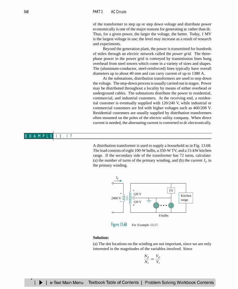
568 PART 2 AC Circuits
of the transformer to step up or step down voltage and distribute powereconomically is one of the major reasons for generating ac rather than dc.Thus, for a given power, the larger the voltage, the better. Today, 1 MVis the largest voltage in use; the level may increase as a result of researchand experiments.
Beyond the generation plant, the power is transmitted for hundredsof miles through an electric network called the power grid. The three-phase power in the power grid is conveyed by transmission lines hungoverhead from steel towers which come in a variety of sizes and shapes.The (aluminum-conductor, steel-reinforced) lines typically have overalldiameters up to about 40 mm and can carry current of up to 1380 A.
At the substations, distribution transformers are used to step downthe voltage. The step-down process is usually carried out in stages. Powermay be distributed throughout a locality by means of either overhead orunderground cables. The substations distribute the power to residential,commercial, and industrial customers. At the receiving end, a residen-tial customer is eventually supplied with 120/240 V, while industrial orcommercial customers are fed with higher voltages such as 460/208 V.Residential customers are usually supplied by distribution transformersoften mounted on the poles of the electric utility company. When directcurrent is needed, the alternating current is converted to dc electronically.
E X A M P L E 1 3 . 1 7
A distribution transformer is used to supply a household as in Fig. 13.68.The load consists of eight 100-W bulbs, a 350-W TV, and a 15-kW kitchenrange. If the secondary side of the transformer has 72 turns, calculate:(a) the number of turns of the primary winding, and (b) the current Ip inthe primary winding.
Ip
2400 V120 V+
−
+
−
120 V–
+
TV
Kitchenrange
8 bulbs
Figure 13.68 For Example 13.17.
Solution:
(a) The dot locations on the winding are not important, since we are onlyinterested in the magnitudes of the variables involved. Since
Np
Ns= Vp
Vs

CHAPTER 13 Magnetically Coupled Circuits 569
we get
Np = NsVp
Vs= 72
2400
240= 720 turns
(b) The total power absorbed by the load is
S = 8 × 100 + 350 + 15,000 = 16.15 kW
But S = VpIp = VsIs , so that
Ip = S
Vp= 16,150
2400= 6.729 A
P R A C T I C E P R O B L E M 1 3 . 1 7
In Example 13.17, if the eight 100-W bulbs are replaced by twelve 60-Wbulbs and the kitchen range is replaced by a 4.5-kW air-conditioner, find:(a) the total power supplied, (b) the current Ip in the primary winding.
Answer: (a) 5.57 kW, (b) 2.321 A.
13.10 SUMMARY1. Two coils are said to be mutually coupled if the magnetic flux φ
emanating from one passes through the other. The mutual induc-tance between the two coils is given by
M = k√L1L2
where k is the coupling coefficient, 0 < k < 1.
2. If v1 and i1 are the voltage and current in coil 1, while v2 and i2 arethe voltage and current in coil 2, then
v1 = L1di1
dt+M
di2
dtand v2 = L2
di2
dt+M
di1
dt
Thus, the voltage induced in a coupled coil consists of self-inducedvoltage and mutual voltage.
3. The polarity of the mutually induced voltage is expressed in theschematic by the dot convention.
4. The energy stored in two coupled coils is
1
2L1i
21 + 1
2L2i
22 ±Mi1i2
5. A transformer is a four-terminal device containing two or moremagnetically coupled coils. It is used in changing the current, volt-age, or impedance level in a circuit.
6. A linear (or loosely coupled) transformer has its coils wound on amagnetically linear material. It can be replaced by an equivalent Tor network for the purposes of analysis.
7. An ideal (or iron-core) transformer is a lossless (R1 = R2 = 0)transformer with unity coupling coefficient (k = 1) and infiniteinductances (L1, L2,M → ∞).

570 PART 2 AC Circuits
8. For an ideal transformer,
V2 = nV1, I2 = I1
n, S1 = S2, ZR = ZL
n2
where n = N2/N1 is the turns ratio. N1 is the number of turns ofthe primary winding and N2 is the number of turns of the secondarywinding. The transformer steps up the primary voltage whenn > 1, steps it down when n < 1, or serves as a matching devicewhen n = 1.
9. An autotransformer is a transformer with a single winding commonto both the primary and the secondary circuits.
10. PSpice is a useful tool for analyzing magnetically coupled circuits.
11. Transformers are necessary in all stages of power distributionsystems. Three-phase voltages may be stepped up or down bythree-phase transformers.
12. Important uses of transformers in electronics applications are aselectrical isolation devices and impedance-matching devices.
R E V I EW QU E S T I ON S
13.1 Refer to the two magnetically coupled coils of Fig.13.69(a). The polarity of the mutual voltage is:(a) Positive (b) Negative
Mi1
(b)
i2M
i1
(a)
i2
Figure 13.69 For Review Questions 13.1 and 13.2.
13.2 For the two magnetically coupled coils of Fig.13.69(b), the polarity of the mutual voltage is:(a) Positive (b) Negative
13.3 The coefficient of coupling for two coils havingL1 = 2 H, L2 = 8 H, M = 3 H is:(a) 0.1875 (b) 0.75(c) 1.333 (d) 5.333
13.4 A transformer is used in stepping down or steppingup:(a) dc voltages (b) ac voltages(c) both dc and ac voltages
13.5 The ideal transformer in Fig. 13.70(a) hasN2/N1 = 10. The ratio V2/V1 is:(a) 10 (b) 0.1 (c) −0.1 (d) −10
N1:N2I1
(a)
I2
+
−
+
−
N1:N2I1
(b)
I2
V1 V2
Figure 13.70 For Review Questions 13.5 and 13.6.
13.6 For the ideal transformer in Fig. 13.70(b),N2/N1 = 10. The ratio I2/I1 is:(a) 10 (b) 0.1 (c) −0.1 (d) −10
13.7 A three-winding transformer is connected asportrayed in Fig. 13.71(a). The value of the outputvoltage Vo is:(a) 10 (b) 6 (c) −6 (d) −10
50 V+
−Vo
2 V
8 V
+
−
(a)
50 V+
−
Vo
2 V
8 V
+
−
(b)
Figure 13.71 For Review Questions 13.7 and 13.8.
13.8 If the three-winding transformer is connected as inFig. 13.71(b), the value of the output voltage Vo is:(a) 10 (b) 6 (c) −6 (d) −10

CHAPTER 13 Magnetically Coupled Circuits 571
13.9 In order to match a source with internal impedanceof 500 to a 15- load, what is needed is:(a) step-up linear transformer(b) step-down linear transformer(c) step-up ideal transformer(d) step-down ideal transformer(e) autotransformer
13.10 Which of these transformers can be used as anisolation device?(a) linear transformer (b) ideal transformer(c) autotransformer (d) all of the above
Answers: 13.1b, 13.2a, 13.3b, 13.4b, 13.5d, 13.6b, 13.7c, 13.8a,13.9d, 13.10b.
P RO B L E M S
Section 13.2 Mutual Inductance
13.1 For the three coupled coils in Fig. 13.72, calculatethe total inductance.
6 H 10 H
2 H
8 H
4 H 5 H
Figure 13.72 For Prob. 13.1.
13.2 Determine the inductance of the three series-connected inductors of Fig. 13.73.
10 H 8 H
4 H
12 H
6 H 6 H
Figure 13.73 For Prob. 13.2.
13.3 Two coils connected in series-aiding fashion have atotal inductance of 250 mH. When connected in aseries-opposing configuration, the coils have a totalinductance of 150 mH. If the inductance of one coil(L1) is three times the other, find L1, L2, and M .What is the coupling coefficient?
13.4 (a) For the coupled coils in Fig. 13.74(a), show that
Leq = L1 + L2 + 2M
(b) For the coupled coils in Fig. 13.74(b), show that
Leq = L1L2 −M2
L1L2 − 2M2
M
L2L1
L1
Leq (b)
M L2
Leq (a)
Figure 13.74 For Prob. 13.4.
13.5 Determine V1 and V2 in terms of I1 and I2 in thecircuit in Fig. 13.75.
+
−
jvMI1
V1
+
−
V2
I2
jvL1 jvL2
R1 R2
Figure 13.75 For Prob. 13.5.
13.6 Find Vo in the circuit of Fig. 13.76.
V
–j6 Ω j8 Ω
+−
j12 Ω
10 Ω
j4 Ω20 30°
+
−
Vo
Figure 13.76 For Prob. 13.6.

572 PART 2 AC Circuits
13.7 Obtain Vo in the circuit of Fig. 13.77.
1 Ω
+− j6 Ω j4 Ω −j3 Ω
4 Ωj2 Ω
Vo
+
−V10 0°
Figure 13.77 For Prob. 13.7.
13.8 Find Vx in the network shown in Fig. 13.78.
2 Ω
+− j4 Ω j4 Ω −j1 Ω
2 Ωj1 Ω
V8 30°
+ −Vx
A2 0°
Figure 13.78 For Prob. 13.8.
13.9 Find Io in the circuit of Fig. 13.79.
Im cos vt
L
C
L
R
io
k = 1
Figure 13.79 For Prob. 13.9.
13.10 Obtain the mesh equations for the circuit in Fig.13.80.
V1
V2
R1
I1 I2
I3
R2
jvL1
jvL2
jvM+−
+ −
jvC1
Figure 13.80 For Prob. 13.10.
13.11 Obtain the Thevenin equivalent circuit for the circuitin Fig. 13.81 at terminals a-b.
j6 Ω
b
a
j8 Ω
2 Ω
j2 Ω
+−V10 90° A4 0°
5 Ω −j3 Ω
Figure 13.81 For Prob. 13.11.
13.12 Find the Norton equivalent for the circuit in Fig.13.82 at terminals a-b.
b
aj20 Ω
j5 Ωj10 Ω+
−V60 30°
20 Ω
Figure 13.82 For Prob. 13.12.
Section 13.3 Energy in a Coupled Circuit
13.13 Determine currents I1, I2, and I3 in the circuit ofFig. 13.83. Find the energy stored in the coupledcoils at t = 2 ms. Take ω = 1000 rad/s.
j10 Ω j10 Ω
4 Ω
k = 0.5
+−A3 90° V20 0°
8 Ω
−j5 Ω
I2I3
I1
Figure 13.83 For Prob. 13.13.
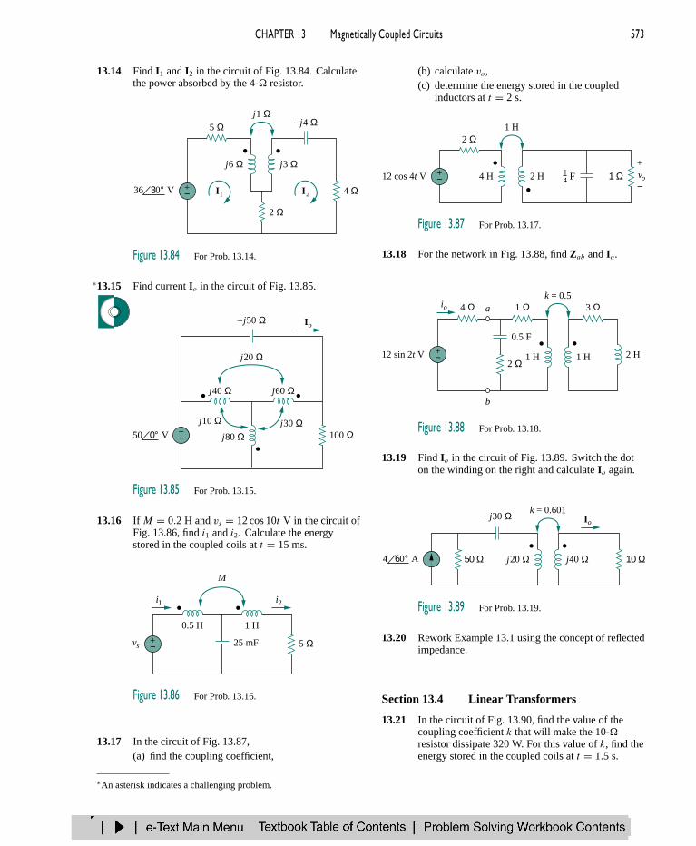
CHAPTER 13 Magnetically Coupled Circuits 573
13.14 Find I1 and I2 in the circuit of Fig. 13.84. Calculatethe power absorbed by the 4- resistor.
5 Ω
4 Ω
j6 Ω j3 Ω
2 Ω
+− I1 I2V36 30°
j1 Ω–j4 Ω
Figure 13.84 For Prob. 13.14.
13.15∗ Find current Io in the circuit of Fig. 13.85.
j80 Ωj30 Ωj10 Ω
j60 Ω
j20 Ω
+−
Io
V50 0° 100 Ω
j40 Ω
–j50 Ω
Figure 13.85 For Prob. 13.15.
13.16 If M = 0.2 H and vs = 12 cos 10t V in the circuit ofFig. 13.86, find i1 and i2. Calculate the energystored in the coupled coils at t = 15 ms.
0.5 H
25 mF
1 H
5 Ω
M
i1 i2
+−vs
Figure 13.86 For Prob. 13.16.
13.17 In the circuit of Fig. 13.87,(a) find the coupling coefficient,
(b) calculate vo,(c) determine the energy stored in the coupled
inductors at t = 2 s.
2 Ω
+− 4 H 2 H 1 Ω vo
1 H
12 cos 4t V+
−F1
4
Figure 13.87 For Prob. 13.17.
13.18 For the network in Fig. 13.88, find Zab and Io.
4 Ω
0.5 F
1 Ω
2 Ω
io
+−12 sin 2t V 1 H 1 H 2 H
k = 0.53 Ωa
b
Figure 13.88 For Prob. 13.18.
13.19 Find Io in the circuit of Fig. 13.89. Switch the doton the winding on the right and calculate Io again.
−j30 Ω
j20 Ω j40 Ω 10 Ω50 Ω
k = 0.601Io
A4 60°
Figure 13.89 For Prob. 13.19.
13.20 Rework Example 13.1 using the concept of reflectedimpedance.
Section 13.4 Linear Transformers
13.21 In the circuit of Fig. 13.90, find the value of thecoupling coefficient k that will make the 10-resistor dissipate 320 W. For this value of k, find theenergy stored in the coupled coils at t = 1.5 s.
∗An asterisk indicates a challenging problem.

574 PART 2 AC Circuits
10 Ω
+− 30 mH 50 mH 20 Ω
k
165 cos 103t V
Figure 13.90 For Prob. 13.21.
13.22 (a) Find the input impedance of the circuit in Fig.13.91 using the concept of reflected impedance.
(b) Obtain the input impedance by replacing thelinear transformer by its T equivalent.
j30 Ω j20 Ω −j6 Ω
j10 Ω8 Ω25 Ωj40 Ω
Zin
Figure 13.91 For Prob. 13.22.
13.23 For the circuit in Fig. 13.92, find:(a) the T -equivalent circuit,(b) the -equivalent circuit.
15 H 20 H
5 H
Figure 13.92 For Prob. 13.23.
13.24∗ Two linear transformers are cascaded as shown inFig. 13.93. Show that
Zin =ω2R(L2
a + LaLb −M2a )
+jω3(L2aLb + LaL
2b − LaM
2b − LbM
2a )
ω2(LaLb + L2b −M2
b )− jωR(La + Lb)
La La
Ma
Lb Lb
Mb
R
Zin
Figure 13.93 For Prob. 13.24.
13.25 Determine the input impedance of the air-coretransformer circuit of Fig. 13.94.
j12 Ω j40 Ω −j5 Ω
j15 Ω20 Ω10 Ω
Zin
Figure 13.94 For Prob. 13.25.
Section 13.5 Ideal Transformers
13.26 As done in Fig. 13.32, obtain the relationshipsbetween terminal voltages and currents for each ofthe ideal transformers in Fig. 13.95.
V1 V2
1:n
+
−
+
−
I1 I2
(a)
V1 V2
1:n
+
−
+
−
I1 I2
(b)
V1 V2
1:n
+
−
+
−
I1 I2
(d)
V1 V2
1:n
+
−
+
−
I1 I2
(c)
Figure 13.95 For Prob. 13.26.
13.27 A 4-kVA, 2300/230-V rms transformer has anequivalent impedance of 2 10 on the primaryside. If the transformer is connected to a load with0.6 power factor leading, calculate the inputimpedance.
13.28 A 1200/240-V rms transformer has impedance60 − 30 on the high-voltage side. If thetransformer is connected to a 0.8 10- load onthe low-voltage side, determine the primary andsecondary currents.
13.29 Determine I1 and I2 in the circuit of Fig. 13.96.
2 Ω10 Ω3:1
I1 I2
+−V14 0°
Figure 13.96 For Prob. 13.29.

CHAPTER 13 Magnetically Coupled Circuits 575
13.30 Obtain V1 and V2 in the ideal transformer circuit ofFig. 13.97.
10 ΩA 12 Ω2 0° A1 0°V1 V2
+
−
+
−
1:4
Figure 13.97 For Prob. 13.30.
13.31 In the ideal transformer circuit of Fig. 13.98, findi1(t) and i2(t).
R1:n
i1(t) i2(t)
+− Vm cos vt
Vodc
Figure 13.98 For Prob. 13.31.
13.32 (a) Find I1 and I2 in the circuit of Fig. 13.99 below.(b) Switch the dot on one of the windings. Find I1
and I2 again.
13.33 For the circuit in Fig. 13.100, find Vo. Switch thedot on the secondary side and find Vo again.
10 Ω
2 Ω
3:1
20 mF
10 cos 5t V +−
+
−Vo
Figure 13.100 For Prob. 13.33.
13.34 Calculate the input impedance for the network inFig. 13.101 below.
13.35 Use the concept of reflected impedance to find theinput impedance and current I1 in Fig. 13.102 below.
12 Ω10 Ωj16 Ω
+−V16 60° 10 30°
I1 I21:2
+−
–j8 Ω
Figure 13.99 For Prob. 13.32.
Zin
1:5 4:1a
b
8 Ω 24 Ω 6 Ωj12 Ω
−j10 Ω
Figure 13.101 For Prob. 13.34.
1:2 1:35 Ω 8 Ω 36 Ω
j18 Ω+−
I1 –j2 Ω
V24 0°
Figure 13.102 For Prob. 13.35.

576 PART 2 AC Circuits
13.36 For the circuit in Fig. 13.103, determine the turnsratio n that will cause maximum average powertransfer to the load. Calculate that maximumaverage power.
40 Ω1:n
+− 10 ΩV rms120 0°
Figure 13.103 For Prob. 13.36.
13.37 Refer to the network in Fig. 13.104.(a) Find n for maximum power supplied to the
200- load.(b) Determine the power in the 200- load if
n = 10.
3 Ω1:n
200 Ω5 ΩA rms4 0°
Figure 13.104 For Prob. 13.37.
13.38 A transformer is used to match an amplifier with an8- load as shown in Fig. 13.105. The Theveninequivalent of the amplifier is: VTh = 10 V,ZTh = 128 .(a) Find the required turns ratio for maximum
energy power transfer.
(b) Determine the primary and secondary currents.(c) Calculate the primary and secondary voltages.
1:n
8 ΩAmplifiercircuit
Figure 13.105 For Prob. 13.38.
13.39 In Fig. 13.106 below, determine the average powerdelivered to Zs .
13.40 Find the power absorbed by the 10- resistor in theideal transformer circuit of Fig. 13.107.
2 Ω
10 Ω
1:2
V46 0°
5 Ω
+−
Figure 13.107 For Prob. 13.40.
13.41 For the ideal transformer circuit of Fig. 13.108below, find:(a) I1 and I2,(b) V1, V2, and Vo,(c) the complex power supplied by the source.
1:10
+−V rms120 0° Zs = 500 – j200 Ω
Zp = 3 + j4 Ω
Figure 13.106 For Prob. 13.39.
12 Ωj3 ΩV1 V2 Vo
− −
1:2
+−V rms60 90°
I1 I22 Ω
+ + +
−
−j6 Ω
Figure 13.108 For Prob. 13.41.

CHAPTER 13 Magnetically Coupled Circuits 577
13.42 Determine the average power absorbed by eachresistor in the circuit of Fig. 13.109.
20 Ω
100 Ω
1:5
80 cos 4t V +−
20 Ω
Figure 13.109 For Prob. 13.42.
13.43 Find the average power delivered to each resistor inthe circuit of Fig. 13.110.
8 Ω
4 Ω
2:1
V20 0° +−
2 Ω
Figure 13.110 For Prob. 13.43.
13.44 Refer to the circuit in Fig. 13.111 below.(a) Find currents I1, I2, and I3.(b) Find the power dissipated in the 40- resistor.
13.45∗ For the circuit in Fig. 13.112 below, find I1, I2, andVo.
13.46 For the network in Fig. 13.113 below, find(a) the complex power supplied by the source,(b) the average power delivered to the 18- resistor.
1:4 1:24 Ω 5 Ω
+−
I1 I2 I3
V120 0° 40 Ω10 Ω
Figure 13.111 For Prob. 13.44.
1:5 3:42 Ω 14 Ω
+−
I1 I2
V24 0° 160 Ω60 ΩVo
+
−
Figure 13.112 For Prob. 13.45.
2:5 1:36 Ω 8 Ω
+−V40 0°
18 Ω
–j20 Ωj4 Ω
j45 Ω
Figure 13.113 For Prob. 13.46.

578 PART 2 AC Circuits
13.47 Find the mesh currents in the circuit of Fig. 13.114below.
Section 13.6 Ideal Autotransformers
13.48 An ideal autotransformer with a 1:4 step-up turnsratio has its secondary connected to a 120- loadand the primary to a 420-V source. Determine theprimary current.
13.49 In the ideal autotransformer of Fig. 13.115, calculateI1, I2, and Io. Find the average power delivered tothe load.
+−
I1
I2
10 + j40 Ω
2 – j6 Ω
Io
20 30° V rms80 turns
200 turns
Figure 13.115 For Prob. 13.49.
13.50∗ In the circuit of Fig. 13.116, ZL is adjusted untilmaximum average power is delivered to ZL. FindZL and the maximum average power transferred toit. Take N1 = 600 turns and N2 = 200 turns.
+−V rms
N1
N2
75 Ω j125 ΩZL
120 0°
Figure 13.116 For Prob. 13.50.
13.51 In the ideal transformer circuit shown in Fig. 13.117,determine the average power delivered to the load.
+−V rms
20 – j40 Ω
120 0°
30 + j12 Ω
1000 turns
200 turns
Figure 13.117 For Prob. 13.51.
13.52 In the autotransformer circuit in Fig. 13.118, showthat
Zin =(
1 + N1
N2
)2
ZL
ZL
Zin
Figure 13.118 For Prob. 13.52.
Section 13.7 Three-Phase Transformers
13.53 In order to meet an emergency, three single-phasetransformers with 12,470/7200 V rms are connectedin -Y to form a three-phase transformer which isfed by a 12,470-V transmission line. If thetransformer supplies 60 MVA to a load, find:(a) the turns ratio for each transformer,(b) the currents in the primary and secondary
windings of the transformer,(c) the incoming and outgoing transmission line
currents.
1:2 1:31 Ω 9 Ω7 Ω
+−V12 0°
–j6 Ω
j18 ΩI1 I1I2
Figure 13.114 For Prob. 13.47.

CHAPTER 13 Magnetically Coupled Circuits 579
13.54 Figure 13.119 below shows a three-phasetransformer that supplies a Y-connected load.(a) Identify the transformer connection.(b) Calculate currents I2 and Ic.(c) Find the average power absorbed by the load.
13.55 Consider the three-phase transformer shown in Fig.13.120. The primary is fed by a three-phase sourcewith line voltage of 2.4 kV rms, while the secondarysupplies a three-phase 120-kW balanced load at pfof 0.8. Determine:(a) the type of transformer connections,(b) the values of ILS and IPS ,(c) the values of ILP and IPP ,(d) the kVA rating of each phase of the transformer.
13.56 A balanced three-phase transformer bank with the-Y connection depicted in Fig. 13.121 below isused to step down line voltages from 4500 V rms to900 V rms. If the transformer feeds a 120-kVA load,find:(a) the turns ratio for the transformer,(b) the line currents at the primary and secondary
sides.
Load120 kW pf = 0.8
4:1
2.4 kV
ILP
ILS
IPS
IPP
Figure 13.120 For Prob. 13.55.
3:1V450 0°
I1
I2
I3
Ic
Ib
Ia
450 120° V
450 –120° V
8 Ω
−j6 Ω
8 Ω
−j6 Ω
8 Ω
−j6 Ω
Figure 13.119 For Prob. 13.54.
1:n
4500 V 900 V 42 kVAThree-phaseload
Figure 13.121 For Prob. 13.56.

580 PART 2 AC Circuits
13.57 A Y- three-phase transformer is connected to a60-kVA load with 0.85 power factor (leading)through a feeder whose impedance is 0.05 + j0.1 per phase, as shown in Fig. 13.122 below. Find themagnitude of:(a) the line current at the load,(b) the line voltage at the secondary side of the
transformer,(c) the line current at the primary side of the
transformer.
13.58 The three-phase system of a town distributes powerwith a line voltage of 13.2 kV. A pole transformerconnected to single wire and ground steps down thehigh-voltage wire to 120 V rms and serves a houseas shown in Fig. 13.123.(a) Calculate the turns ratio of the pole transformer
to get 120 V.(b) Determine how much current a 100-W lamp
connected to the 120-V hot line draws from thehigh-voltage line.
13.2 kV 120 V
Figure 13.123 For Prob. 13.58.
Section 13.8 PSpice Analysis of MagneticallyCoupled Circuits
13.59 Rework Prob. 13.14 using PSpice.
13.60 Use PSpice to find I1, I2, and I3 in the circuit of Fig.13.124.
j15 Ω
j80 Ωj0 Ω
j100 Ω
j10 Ω
+−V60 0°
j50 Ω –j20 Ω
20 90°+− V
I1 I3
I2
40 Ω
80 Ω
Figure 13.124 For Prob. 13.60.
13.61 Rework Prob. 13.15 using PSpice.
13.62 Use PSpice to find I1, I2, and I3 in the circuit of Fig.13.125.
I1 I2
I3
100 Ω
8 H
2 H
1 H
4 H 3 H
2 H 60 mF
200 Ω
70 Ω 50 mF
+−
V120 0°f = 100
Figure 13.125 For Prob. 13.62.
1:n
0.05 Ω j0.1 Ω
0.05 Ω j0.1 Ω
0.05 Ω j0.1 Ω
Balancedload
60 kVA0.85 pfleading
2640 V
240 V
Figure 13.122 For Prob. 13.57.

CHAPTER 13 Magnetically Coupled Circuits 581
13.63 Use PSpice to find V1, V2, and Io in the circuit ofFig. 13.126.
2 Ω1:2
+−
20 Ω
16 Ω
V1 V2
+
−
+
−V40 60° +
− V30 0°
–j12 Ω–j4 Ω
j8 Ω
Io
Figure 13.126 For Prob. 13.63.
13.64 Find Ix and Vx in the circuit of Fig. 13.127 belowusing PSpice.
13.65 Determine I1, I2, and I3 in the ideal transformercircuit of Fig. 13.128 using PSpice.
j80 Ω
−j30 Ω
50 Ω
+−
I1 I21:2
1:3V440 0°
40 Ω
j50 Ω
I3 60 Ω
Figure 13.128 For Prob. 13.65.
Section 13.9 Applications
13.66 A stereo amplifier circuit with an output impedanceof 7.2 k is to be matched to a speaker with an inputimpedance of 8 by a transformer whose primary
side has 3000 turns. Calculate the number of turnsrequired on the secondary side.
13.67 A transformer having 2400 turns on the primary and48 turns on the secondary is used as animpedance-matching device. What is the reflectedvalue of a 3- load connected to the secondary?
13.68 A radio receiver has an input resistance of 300 .When it is connected directly to an antenna systemwith a characteristic impedance of 75 , animpedance mismatch occurs. By inserting animpedance-matching transformer ahead of thereceiver, maximum power can be realized. Calculatethe required turns ratio.
13.69 A step-down power transformer with a turns ratio ofn = 0.1 supplies 12.6 V rms to a resistive load. Ifthe primary current is 2.5 A rms, how much power isdelivered to the load?
13.70 A 240/120-V rms power transformer is rated at10 kVA. Determine the turns ratio, the primarycurrent, and the secondary current.
13.71 A 4-kVA, 2400/240-V rms transformer has 250turns on the primary side. Calculate:(a) the turns ratio,(b) the number of turns on the secondary side,(c) the primary and secondary currents.
13.72 A 25,000/240-V rms distribution transformer has aprimary current rating of 75 A.(a) Find the transformer kVA rating.(b) Calculate the secondary current.
13.73 A 4800-V rms transmission line feeds a distributiontransformer with 1200 turns on the primary and 28turns on the secondary. When a 10- load isconnected across the secondary, find:(a) the secondary voltage,(b) the primary and secondary currents,(c) the power supplied to the load.
1:2 2:11 Ω 6 Ω
2Vx
8 Ωj2 Ω
+−
Ix –j10 Ω
V6 0°+
−Vx
4 Ω+
−
Vo
+ −
Figure 13.127 For Prob. 13.64.

582 PART 2 AC Circuits
COM P R E H EN S I V E P RO B L E M S
13.74 A four-winding transformer (Fig. 13.129) is oftenused in equipment (e.g., PCs, VCRs) that may beoperated from either 110 V or 220 V. This makes theequipment suitable for both domestic and foreignuse. Show which connections are necessary toprovide:(a) an output of 12 V with an input of 110 V,(b) an output of 50 V with an input of 220 V.
a
b
c
d
e
f
g
h
32 V
18 V
110 V
110 V
Figure 13.129 For Prob. 13.74.
13.75∗ A 440/110-V ideal transformer can be connected tobecome a 550/440-V ideal autotransformer. There
are four possible connections, two of which arewrong. Find the output voltage of:(a) a wrong connection,(b) the right connection.
13.76 Ten bulbs in parallel are supplied by a 7200/120-Vtransformer as shown in Fig. 13.130, where thebulbs are modeled by the 144- resistors. Find:(a) the turns ratio n,(b) the current through the primary winding.
1:n
144 Ω7200 V 120 V 144 Ω
Figure 13.130 For Prob. 13.76.