The Indian Health Service Health Care Facilities Construction
1
CHAPTER 13
Health Care Facilities and MEDICAL GAS and Vacuum SYSTEMS
Part I – Special Requirements for Health Care Facilities.
1301.0 Application.
1301.1 Construction and equipment requirements shall be applied only to new construction
and new equipment, except as modified in individual chapters. Only the altered, renovated,
or modernized portion of an existing system or individual component shall be required to
meet the installation and equipment requirements stated in this standard code. If the
alteration, renovation, or modernization adversely impacts existing performance
requirements of a system or component, additional upgrading shall be required. [NFPA
99:1.3.2 – 1.3.2.2]
1301.2 This chapter applies to the special fixtures and systems in health care facilities and
to the special plumbing requirements for such facilities. Other plumbing in such facilities
shall comply with other applicable sections of this code.
1301.3 This chapter shall not apply to breathing air replenishment (BAR) systems.
1302.0 Medical Gas and Vacuum Piping Systems – Installation Requirements.
The installation of medical gas and vacuum piping systems shall be in accordance with the
requirements of this chapter and/or the appropriate standards adopted in this code by the
Authority Having Jurisdiction State Plumbing Board. For additional standards, see Table
14-1.
1302.1 The installation of individual components shall be made in accordance with the
instructions of the manufacturer. Such instructions shall include directions and information
deemed by the manufacturer to be adequate for attaining proper operation, testing, and
maintenance of the medical gas and vacuum systems. Copies of the manufacturer's
instructions shall be left with the system owner. [NFPA 99:5.1.10.10.9.1 – 5.1.10.10.9.3]
[NFPA 99:5.1.10.11.8.0 – 5.1.10.11.8.3]
1303.0 Protrusions from Walls.
1303.1 Drinking fountain control valves shall be flush-mounted or fully recessed when
installed in corridors or other areas where patients are transported on a gurney, bed, or
wheelchair.
1303.2 Piping exposed in corridors and other areas where subject to physical damage from
the movement of carts, stretchers, portable equipment, or vehicles shall be protected.
[NFPA 99:5.1.10.10.2.1] [NFPA 99:5.1.10.11.2.1]
1304.0 Psychiatric Patient Rooms.
Piping and drain traps in psychiatric patient rooms shall be concealed. Fixtures and fittings
shall be resistant to vandalism.
1305.0 Locations for Ice Storage.
Ice makers or ice storage containers shall be located in nursing stations or similarly
supervised areas to minimize potential contamination.

2
1306.0 Sterilizers.
1306.1 General. The requirements of this section apply to sterilizers and bedpan steamers.
Such equipment shall be installed in accordance with this code and the manufacturer’s
installation instructions.
1306.2 Indirect Waste Connections. Waste drainage from sterilizers and bedpan steamers
shall be connected to the sanitary drainage system through an airgap in accordance with this
chapter and Chapter 8. The size of indirect waste piping shall be not less than the size of the
drain connection on the fixture. Each such indirect waste pipe shall not exceed fifteen (15)
feet (4,572 mm) in length and shall be separately piped to a receptor. Such receptors shall
be located in the same room as the equipment served. Except for bedpan steamers, such
indirect waste pipes shall not require traps. A trap having a seal of not less than three (3)
inches (76 mm) shall be provided in the indirect waste pipe for a bedpan steamer.
1307.0 Vapor Vents and Stacks for Sterilizers.
1307.1 General. When a sterilizer has provision for a vapor vent and such a vent is required
by the manufacturer, the vent shall be extended to the outdoors above the roof. Sterilizer
vapor vents shall be installed in accordance with the manufacturer’s instructions and shall
not be connected to any drainage system vent.
1308.0 Aspirators.
1308.1 (See Section 603.4.9, Water Inlets to Water Supplied Aspirators.) Provisions for
aspirators or other water-supplied suction devices shall be installed only with the specific
approval of the Authority Having Jurisdiction building official. Where aspirators are used
for removing body fluids, they shall include a collection container to collect liquids and
solid particles. Aspirators shall indirectly discharge to the sanitary drainage system through
an airgap in accordance with Chapter 8. The potable water supply to an aspirator shall be
protected by a vacuum breaker or equivalent backflow protection device in accordance with
Section 603.0.
Part II – Medical Gas and Vacuum Systems.
1309.0 Application.
1309.1 The provisions herein shall apply to the installation and testing of medical gas and
vacuum piping in hospitals, clinics, and other health care facilities.
1309.2 The purpose of this chapter is to provide requirements for the installation and testing
of medical gas and medical vacuum systems, from the central supply system to the station
outlets or inlets.
1309.3 Wherever the terms medical gas or vacuum occur, the provisions shall apply to
piped systems for oxygen, nitrous oxide, medical air, carbon dioxide, helium, medical–
surgical vacuum, waste anesthetic gas disposal, nitrogen, instrument air, and mixtures
thereof. Wherever the name of a specific gas or vacuum service occurs, the provision shall
apply only to that gas. [NFPA 99:5.1.1.2, 5.1.1.3]
1309.4 This chapter does not apply to portable compressed gas systems.
1309.5 This chapter does not apply to:

3
(A) Cylinder and container management, storage, and reserve requirements.
(B) Gas central supply and bulk supply systems, except as addressed in this chapter.
(C) Electrical connections and requirements.
(D) Motor requirements and controls.
(E) Systems having nonstandard operating pressures, except as addressed in this chapter.
(F) Waste anesthetic gas disposal (WAGD) systems.
(G) Surface-mounted medical gas rail systems
1309.6 The requirements of this chapter shall not be interpreted to conflict with the
requirements of NFPA 99, Standard for Health Care Facilities. For requirements of
portions of medical gas and medical vacuum systems not addressed in this chapter or
medical gas and medical vacuum systems beyond the scope of this chapter refer to NFPA
99, Standard for Health Care Facilities.
1309.7 An existing system that is not in strict compliance with the provisions of the
standard (Code) shall be permitted to be continued in use as long as the Authority Having
Jurisdiction building official has determined that such use does not constitute a distinct
hazard to life. [NFPA 99:5.1.1.4]
1310.0 Definitions.
1310.1 Building Supply – The pipe from the source of supply to a building or structure.
1310.2 Critical Care Area Room – Those special care units, intensive care units, coronary
care units, angiography laboratories, cardiac catheterization laboratories, delivery rooms,
operating rooms, post anesthesia recovery rooms, emergency departments, and similar areas
in which patients are intended to be subjected to invasive procedures and connected to line-
operated, patient-care-related electrical appliances. [NFPA 99:3.3.138.1] These rooms are
typically where patients are intended to be subjected to invasive procedures and
connected to line-operated, patient care-related appliances. Examples include, but are
not limited to, special care patient rooms used for critical care, intensive care, and
special care treatment rooms such as angiography laboratories, cardiac
catheterization laboratories, delivery rooms, operating rooms, post-anesthesia care
units, trauma rooms, and other similar rooms.
1310.3 General Care Areas Room – General care areas are patient bedrooms, examining
rooms, treatment rooms, clinics, and similar areas in which it is intended that the patient
will come in contact with ordinary appliances such as a nurses-call system, electric beds,
examining lamps, telephones, and entertainment devices. [NFPA 99:3.3.138.2] Examples
include, but are not limited to, inpatient bedrooms, dialysis rooms, in vitro fertilization
rooms, procedural rooms and similar rooms.
1310.4 Manifold – A device for connecting outlets of one (1) or more gas cylinders to the
central piping system for that specific gas. [NFPA 99:3.3.103] [NFPA 99:3.3.101]
1310.5 Medical Air – For purposes of this standard, medical air is air supplied from
cylinders, bulk containers, medical air compressors, or has been reconstituted from oxygen
USP and oil-free, dry nitrogen NF. [NFPA 99:3.3.104] Medical air shall be required to have
the following characteristics:[NFPA 99:3.3.106]
(1) Be supplied from cylinders, bulk containers, medical air compressor sources, or be
reconstituted from oxygen USP and oil-free dry nitrogen NF.
4
(2) Meet the requirements of medical air USP.
(3) Have no detectable liquid hydrocarbons.
(4) Have less than twenty-five (25) ppm gaseous hydrocarbons.
(5) Have equal to or less than 1.8 E-10 pounds per cubic inch (lb/in3) five (5) mg/m3 of
permanent particulates sized one (1) micron or larger in the air at normal atmospheric
pressure. [NFPA 99:5.1.3.5.1(1)-(5)]
1310.6 Medical Gas – Gas used in a medical facility, including oxygen, nitrous oxide,
carbon dioxide, helium, medical air, and mixtures of these gases. Standards of purity apply.
A patient medical gas or medical support gas. [NFPA 99:3.3.107] (see also NFPA
99:3.3.109, medical support gas and NFPA 99:3.3.142, patient medical gas)
1310.7 Medical Gas System – Complete system consisting of a central supply system
(manifold, bulk, or compressors), including control equipment and piping extending to
station outlets at the points where medical gases are required. An assembly of equipment
and piping for the distribution of nonflammable medical gases such as oxygen, nitrous
oxide, compressed air, carbon dioxide, and helium. [NFPA 99:3.3.108]
1310.8 Medical Vacuum System – See 1310.19, Vacuum System – Level Category 1.
1310.9 Nitrogen, NF (Oil-Free, Dry) (Nitrogen for Brazing and Testing) – Nitrogen
complying, at a minimum, with oil-free, dry nitrogen NF. [NFPA 99:3.3.120.1] [NFPA
99:3.3.118.1]
1310.10 Patient Care Area – Any portion room of a health care facility wherein patients
are intended to be examined or treated. [NFPA 99:3.3.138]
1310.11 Purge, Flow – The removal of oxygen from a system by oil-free dry nitrogen
during brazing.
1310.12 Purge, System – The removal of nitrogen from a system with the medical gas
required for that system.
1310.13 SCFM – Standard cubic feet per minute. [NFPA 99:3.3.163]
1310.14 Special Hazard Area – An area such as a kitchen or electrical switch-gear room.
1310.15 Station Inlet – An inlet point in a medical-surgical piped vacuum distribution
system at which the user makes connections and disconnections. [NFPA 99:3.3.171]
[NFPA 99:3.3.169]
1310.16 Station Outlet – An inlet point in a piped medical/surgical vacuum distribution
system at which the user makes connections and disconnections. [NFPA 99:3.3.172]
[NFPA 99:3.3.170]
1310.17 Use Point – A room or area of a room where medical gases are dispensed to a
single patient for medical purposes. A use point is permitted to be comprised of a number of
station outlets of different gases. [NFPA 99:3.3.180] [NFPA 99:3.3.179]
1310.18 User Outlet – See Station Outlet.
1310.19 Vacuum System – Level Category 1 – A system consisting of central vacuum-
producing equipment with pressure and operating controls, shutoff valves, alarm warning
systems, gauges, and a network of piping extending to and terminating with suitable station
inlets at locations where patient suction could be required. [NFPA 99:3.3.91] [NFPA
99:3.3.111]
1310.20 Valve, Isolation – A valve that isolates one (1) piece of equipment from another.

5
1310.21 Valve, Riser – A valve at the base of a vertical riser that isolates that riser.
1310.22 Valve, Service – A valve serving horizontal piping extending from a riser to a
station outlet or inlet.
1310.23 Valve, Source – A single valve at the source that controls a number of units that
make up the source.
1310.24 Valve, Zone – A valve that controls the gas or vacuum to a particular area.
1310.25 Waste Anesthetic Gas Disposal – The process of capturing and carrying away
gases vented from the patient breathing circuit during the normal operation of gas
anesthesia or analgesia equipment. [NFPA 99:3.3.184] [NFPA 99:3.3.183]
1310.26 Piped Vacuum System – Level Category 3 – A vacuum distribution system that
can be either a wet or dry system designed to remove liquids, air-gas, or solids from the
treatment area. [NFPA 99 3.3.95] [NFPA 99:3.3.23]
1310.27 Compressed Air System – Level Category 3 – A system of component parts that
delivers compressed air to power devices. [NFPA 99 3.3.93] [NFPA 99:5.3.7.6]
1310.28 – Level Category 1 – Medical gas and vacuum systems serve occupancies where
interruption of the piped gas and vacuum systems would place patients in imminent danger
of morbidity or mortality. [NFPA 99 3.3.90] Facility systems in which failure of such
equipment or system is likely to cause injury or death of patients or caregivers shall be
designed to meet system category 1 requirements.[NFPA 99 4.1.1]
1310.29 – Level Category 2 – Medical gas and vacuum systems serve occupancies where
interruption of the piped gas and vacuum systems would place patients at manageable risk
of morbidity or mortality. [NFPA 99 3.3.92] Facility systems in which failure of such
equipment is likely to cause minor injury to patients or caregivers shall be designed to
meet system category 2 requirements. [NFPA 99 4.1.2]
1310.30 – Level Category 3 – Medical gas and vacuum systems serve occupancies where
interruption of the piped gas and vacuum systems would terminate procedures, but would
not place patients at risk of morbidity or mortality. [NFPA 99 3.3.94] Facility systems in
which failure of such equipment is not likely to cause injury to patients or caregivers,
but can cause patient discomfort, shall be designed to meet system category 3
requirements. [NFPA 99 4.1.3]
1310.31- Category 4 – Facility systems in which failure of such equipment would have
no impact on patient care shall be designed to meet system category 4 requirements as
defined in this code.[ NFPA 99 4.1.4]
1311.0 General Requirements.
1311.1 Oxygen Compatibility. Tubes, valves, fittings, station outlets, and other piping
components in medical gas systems shall have been cleaned for oxygen service by the
manufacturer prior to installation in accordance with CGA 4.1, Cleaning Equipment for
Oxygen Service, except that fittings shall be permitted to be cleaned by a supplier or agency
other than the manufacturer. [NFPA 99:5.1.10.1.1]
1311.1.1 Components include but are not limited to containers, valves, valve seats,
lubricants, fittings, gaskets, and interconnecting equipment including hose. Easily
ignitable materials should be avoided.

6
Compatibility involves both combustibility and ease of ignition. Materials that burn in
air will burn violently in pure oxygen at normal pressure and explosively in pressurized
oxygen. Also, many materials that do not burn in air will do so in pure oxygen,
particularly under pressure. Metals for containers and piping have to be carefully
selected, depending on service conditions. The various steels are acceptable for many
applications, but some service conditions can call for other materials (usually copper or
its alloys) because of their greater resistance to ignition and lower rate of combustion.
Similarly, materials that can be ignited in air have lower ignition energies in oxygen.
Many such materials can be ignited by friction at a valve seat, stem packing or by
adiabatic compression produced when oxygen at high pressure is rapidly introduced into
a system initially at low pressure.
1311.1.2 Materials used in central supply systems shall meet the following requirement
[NFPA 99:5.1.3.4.4]:
In those portions of systems intended to handle oxygen or nitrous oxide at gauge
pressures of less than three-hundred (300) (350)psi (2,070 kPa), material construction
shall be compatible with oxygen under the temperatures and pressures to which the
components can be exposed in the containment and use of oxygen, nitrous oxide,
mixtures of these gases, or mixtures containing more than 23.5 percent oxygen. [NFPA
99:5.1.3.4.4(1), (2)]
1311.1.3 Each length of tube shall be delivered plugged or capped by the manufacturer
and kept sealed until prepared for installation. Fittings, valves, and other components
shall be delivered sealed, labeled, and kept sealed until prepared for installation. [NFPA
99:5.1.10.1.2 and 5.1.10.1.3]
1311.4 Medical gas and medical vacuum systems shall be supplied from a source consisting
of not less than two (2) units – primary and secondary, e.g., a manifold consisting of two (2)
cylinder banks with not less than two (2) cylinders in each bank, not less than two (2) air
compressors, or not less than two (2) vacuum pumps. However, two (2) supply pipelines are
not required.
1312.0 Plan Review.
1312.1 Before any medical gas or medical vacuum system is installed or altered in any
hospital, medical facility, or clinic, duplicate plans and specifications shall be filed with the
Authority Having Jurisdiction building official. Approval of the plans shall be obtained
prior to issuance of any permit by the Authority Having Jurisdiction building official.
1312.2 Plans and specifications shall show the following, in detail:
1312.2.1 Plot plan of the site, drawn to scale, indicating the location of existing or new
cylinder storage areas, property lines, driveways, and existing or proposed buildings.
1312.2.2 Piping layout of the proposed piping system or alteration, including alarms,
valves, origin of gases, and user outlets/inlets. The demand and loading of any piping,
existing or future, shall also be indicated.
1312.2.3 Complete specification of materials.
1312.3 Plans and specifications submitted to the Authority Having Jurisdiction building
official shall clearly indicate the nature and extent of the work proposed and shall show in
detail that such work will conform to the provisions of this code.
7
1312.4 A record of as-built plans and valve identification records shall remain on the site at
all times.
1313.0 System Performance.
1313.1 Required Operating Pressures. Medical gas and medical vacuum systems shall be
capable of delivering service in the pressure ranges listed in Table 13-1.
1313.2 Minimum Flow Rates. Medical gas and medical vacuum systems shall be capable
of supplying the flow rates listed in Table 13-2.
1313.3 Minimum Station Outlets/Inlets. Station outlets and inlets for medical gas and
medical vacuum systems shall be provided as listed in Table 13-3.
1314.0 Required Pipe Sizing.
1314.1 Where the maximum demand for each medical gas or vacuum system and the
maximum length of piping between the source equipment and the most distant station
outlet/inlet do not exceed the values in Table 13-6, the size of pipe of each section of the
system shall be determined using Tables 13-4 and 13-6. The size for systems beyond the
range of Table 13-6 shall be determined by using the methods set forth in Section 1314.3 of
this chapter.
1314.2 To determine the size of each section of pipe in any system within the range of
Table 13-6, proceed as follows:
1314.2.1 Measure the length of the pipe from the source equipment location to the most
remote station inlet/outlet on the system.
1314.2.2 In Table 13-6, select the column showing that distance, or the next longer
distance if the table does not give the exact length.
1314.2.3 Starting at the most remote outlet/inlet, find in the vertical column just selected
the medical gas or vacuum demand for that inlet/ outlet. If the exact figure of demand is
not shown, choose the next larger figure below in the column.
1314.2.4 Opposite this demand figure, in the first column at the left in Table 13-6, will
be found the correct size of pipe.
1314.2.5 Using this same vertical column, proceed in a similar manner for each section
of pipe serving this inlet/outlet. For each section of pipe, determine the total gas or
vacuum demand supplied by the section, using Table 13-4.
1314.2.6 Size each section of branch piping not previously sized by measuring the
distance from the source equipment location to the most remote inlet/outlet in that
branch, and follow the procedures of Sections 1314.2.2 through 1314.2.5.
Note: Size branch piping in the order of the distance from the source location, beginning
with the most distant outlet not previously sized.
1314.3 For conditions other than those covered by Section 1314.1 of this section, such as
longer runs of greater gas or vacuum demands, the size of each gas or vacuum piping
system shall be determined by standard engineering methods acceptable to the Authority
Having Jurisdiction building official, and each system shall be so designed that the total
pressure drop or gain between the source equipment and any inlet/outlet shall not exceed the
allowable pressures shown in Table 13-1.

8
1315.0 Workmanship.
1315.1 Design, construction, and workmanship shall be in conformity with accepted
engineering practices and shall meet the requirements of this code.
1315.2 Cracks, holes, or other imperfections in materials shall not be concealed by welding,
brazing, or soldering, or by using paint, wax, tar, other leak-sealing or repair agents.
1315.3 Burred ends of all tubing shall be deburred using a deburring tool to the full bore of
the tube, and all chips shall be removed.
1316.0 Materials.
The provisions of this section apply to the field-installed piping for the distribution of
medical piped gases.
1316.1 Tubes, valves, fittings, station outlets, and other piping components in medical gas
systems shall have been cleaned for oxygen service by the manufacturer prior to installation
in accordance with CGA 4.1, Cleaning Equipment for Oxygen Service, except that fittings
shall be permitted to be cleaned by a supplier or agency other than the manufacturer. [NFPA
99:5.1.10.1.1]
1316.2 Each length of tube shall be delivered plugged or capped by the manufacturer and
kept sealed until prepared for installation. Fittings, valves, and other components shall be
delivered sealed, labeled, and kept sealed until prepared for installation. [NFPA
99:5.1.10.1.2, 5.1.10.1.3]
1316.3 Tubes shall be hard-drawn seamless copper ASTM B 819 medical gas tube, Type L,
except that where operating pressures are exceeding a gauge pressure of one-hundred and
eighty-five (185) psi (1,275 kPa), Type K shall be used for sizes exceeding DN80 (NPS 3)
(3-1/8 in. O.D.).
ASTM B 819 medical gas tube shall be identified by the manufacturer's markings
"OXY," "MED," "OXY/MED," "OXY/ACR," or "ACR/MED" in blue (Type L) or green
(Type K). [NFPA 99:5.1.10.1.4, 5.1.10.1.5]
Piping for vacuum systems shall be constructed of any of the following:
(1) Hard-drawn seamless copper tube:
(a) ASTM B 88, Standard Specification for Seamless Copper Water Tube, (Types K, L,
M).
(b) ASTM B 280, Standard Specification for Seamless Copper Tubing for Air
Conditioning and Refrigeration Field Service (copper ACR tube).
(c) ASTM B 819, Standard Specification for Seamless Copper Tube for Medical Gas
Systems, copper medical gas tubing (Type K or L).
(2) Stainless steel tube. [NFPA 99:5.1.10.2.1]:
Piping systems shall be designed and sized to deliver the required flow rates at the
utilization pressures.
Mains and branches in medical gas-piping systems shall be not less than DN15 (NPS
1/2) (5/8 in. O.D.) size.
Mains and branches in medical-surgical vacuum systems shall be not less than DN20
(NPS 3/4) (7/8 in. O.D.) size.

9
Drops to individual station outlets and inlets shall be not less than DN15 (NPS 1/2) (5/8
in. O.D.) size.
Runouts to alarm panels and connecting tubing for gauges and alarm devices shall be
permitted to be DN8 (NPS 1/4) (3/8 in. O.D.) size. [NFPA 99:5.1.10.10.1.1 – 5.1.10.10.1.5]
1316.4 Turns, offsets, and other changes in direction in welded or brazed medical gas and
vacuum piping shall be made with wrought-copper capillary fittings complying with ASME
B16.22, Wrought Copper and Copper Alloy Solder-Joint Pressure Fittings, or brazed
fittings complying with ASME B16.50, Wrought Copper and Copper Alloy Braze-Joint
Pressure Fittings. [NFPA 99:5.1.10.3.1]
1316.4.1 Cast-copper alloy fittings shall not be permitted. [NFPA 99:5.1.10.3.2]
1316.4.2 Branch connections in vacuum piping systems shall be permitted to be made
using mechanically formed, drilled, and extruded tee-branch connections that are
formed in accordance with the tool manufacturer's instructions and brazed. [NFPA
99:5.1.10.3.3]
1316.5 The following special fittings shall be permitted to be used in lieu of brazed joints:
(1) Memory-metal couplings having temperature and pressure ratings joints not less than
that of a brazed joint.
(2) Listed or approved metallic gas tube fittings that, when made up, provide a permanent
joint having the mechanical, thermal, and sealing integrity of a brazed joint.
(3) Dielectric fittings, where required by the manufacturer of special medical equipment to
electrically isolate the equipment from the piping distribution system.
1316.6 The following joints shall be prohibited throughout medical gas and vacuum
distribution pipeline systems:
(1) Flared and compression-type connections, including connections to station outlets and
inlets, alarm devices, and other components.
(2) Other straight-threaded connections, including unions.
(3) The use of pipe-crimping tools to permanently stop the flow.
(4) Removable and no removable push-fit fittings that employ a quick assembly push-
fit connector. [NFPA 99:5.1.10.8] [NFPA 99: 5.1.10.10]
1316.6.1Threaded joints in medical gas and vacuum distribution piping shall meet the
following requirements:
(1) Be limited to connections to pressure/ vacuum indicators, alarm devices, and source
equipment.
(2) Be tapered pipe threads complying with ASME B1.20.1, Pipe Threads General
Purpose, Inc.
(3) Be made up with polytetrafluoroethylene (such as Teflon™) tape or other thread
sealant recommended for oxygen service, with the sealant applied to the male
threads only. [NFPA 99:5.1.10.4] [NFPA 99:5.1.10.8]
1316.7 New or replacement shutoff valves shall be as follows:
(1) Quarter turn, full ported ball type.
(2) Brass or bronze construction.
(3) Have extensions for brazing.

10
(4) Have a handle indicating open or closed.
(5) Consist of three pieces permitting in-line serviceability. [NFPA 99:5.1.4.3]
1316.8 Soldered joints in copper Level 3 vacuum and Level 3 Category 3 gas-powered
systems piping shall be made in accordance with ASTM B 828, Making Capillary Joints by
Soldering of Copper and Copper Alloy Tube and Fittings, using a lead-free solder filler
metal containing not more than 0.2 percent lead by volume that complies with ASTM B
32, standard specification for solder metal.. [NFPA 99:5.3.10.5] [NFPA 99: 5.3.7.2.3.3]
1317.0 Cleaning for Medical Gas Piping Systems.
1317.1 The interior surfaces of tube ends, fittings, and other components that were cleaned
for oxygen service by the manufacturer, but become contaminated prior to being installed,
shall be permitted to be recleaned on-site by the installer by thoroughly scrubbing the
interior surfaces with a clean, hot water–alkaline solution, such as sodium carbonate or
trisodium phosphate one (1) pound to three (3) gallons (450 g to 11 L) of potable water and
thoroughly rinsing them with clean, hot potable water. Other aqueous cleaning solutions
shall be permitted to be used for on-site recleaning permitted above, provided that they are
as recommended in CGA Pamphlet G-4.1, Cleaning Equipment for Oxygen Service, and are
listed in CGA Pamphlet O2-DIR, Directory of Cleaning Agents for Oxygen Service. [NFPA
99:5.1.10.5.3.10 and 5.1.10.5.3.11]
1317.2 Material that has become contaminated internally and is not clean for oxygen service
shall not be installed. [NFPA 99:5.1.10.5.3.12]
1318.0 Installation of Piping.
1318.1 Piping shall be protected against freezing, corrosion, and physical damage.
[NFPA 99:5.1.10.10.2] [NFPA 99: 5.1.10.11.2]
Piping exposed in corridors and other areas where subject to physical damage from the
movement of carts, stretchers, portable equipment, or vehicles shall be protected. [NFPA
99:5.1.10.10.2.1] [NFPA 99: 5.1.10.11.2.1]
Piping underground within buildings or embedded in concrete floors or walls shall be
installed in a continuous conduit. [NFPA 99:5.1.10.10.2.2] [NFPA 99: 5.1.10.11.2.2]
1318.2 Piping risers shall be permitted to be installed in pipe shafts if protected from
physical damage, effects of excessive heat, corrosion, or contact with oil.
Piping shall not be installed in kitchens, elevator shafts, elevator machine rooms, areas
with open flames, electrical service equipment exceeding 600 volts, and areas prohibited
under NFPA 70, National Electrical Code, except for the following locations:
(1) Room locations for medical air compressor supply systems and medical-surgical
vacuum pump supply systems.
(2) Room locations for secondary distribution circuit panels and breakers having a
maximum voltage rating of 600 volts.
Medical gas piping shall be permitted to be installed in the same service trench or tunnel
with fuel gas lines, fuel oil lines, electrical lines, steam lines, and similar utilities provided
that the space is ventilated (naturally or mechanically) and the ambient temperature around
the medical gas piping shall not exceed 130°F (54°C ).

11
Medical gas piping shall not be located where subject to contact with oil, including a
possible flooding area in the case of a major oil leak. [NFPA 99:5.1.10.10.3] [NFPA 99:
5.1.10.11.3.1 – 5.1.10.11.3.4]
1318.3 Buried piping outside of buildings shall be installed below the local level of frost
penetration. [NFPA 99:5.1.10.10.5.1] [NFPA 99:5.1.10.11.5.1]
1318.4 The installation procedure for underground piping shall protect the piping from
physical damage while being backfilled. [NFPA 99:5.1.10.10.5.2] [NFPA 99:5.1.10.11.5.2]
If underground piping is protected by a conduit, cover, or other enclosure, the following
requirements shall be met [NFPA 99:5.1.10.10.5.3] [NFPA 99:5.1.10.11.5.3]:
(1) Access shall be provided at the joints for visual inspection and leak testing.
(2) The conduit, cover, or enclosure shall be self-draining and not retain groundwater in
prolonged contact with the pipe.
Buried piping that will be subject to surface loads shall be buried at a depth that will
protect the piping and its enclosure from excessive stresses. [NFPA 99:5.1.10.10.5.4]
[NFPA 99:5.1.10.11.5.4]
The minimum backfilled cover above the top of the pipe or its enclosure for buried
piping outside of buildings shall be thirty-six (36) inches (900 mm), except that the
minimum cover shall be permitted to be reduced to eighteen (18) inches (450 mm) where
physical damage is otherwise prevented. [NFPA 99:5.1.10.10.5.5] [NFPA 99:5.1.10.11.5.5]
Trenches shall be excavated so that the pipe enclosure has firm, substantially continuous
bearing on the bottom of the trench. [NFPA 99:5.1.10.10.5.6] [NFPA 99:5.1.10.11.5.6]
Backfill shall be clean, free from material that can damage the pipe, and compacted.
so as to protect and uniformly support the pipe enclosure. [NFPA 99:5.1.10.10.5.7] [NFPA
99:5.1.10.11.5.7]
A continuous tape or marker placed immediately above the enclosure shall clearly
identify the pipeline by specific name. [NFPA 99:5.1.10.10.5.8] [NFPA 99:5.1.10.11.5.8]
A continuous warning means shall also be provided above the pipeline at approximately
one-half (1/2) the depth of bury. [NFPA 99:5.1.10.10.5.9] [NFPA 99:5.1.10.11.5.9]
Where underground piping is installed through a wall sleeve, the ends of the sleeve shall
be sealed to prevent the entrance of groundwater into the building. [NFPA
99:5.1.10.10.5.10] [NFPA 99:5.1.10.11.5.10]
1318.5 Hose and flexible connectors, both metallic and nonmetallic, shall be no longer than
necessary and shall not penetrate or be concealed in walls, floors, ceilings, or partitions.
Flexible connectors, metallic or nonmetallic, shall have a minimum burst pressure, with a
gauge pressure of one-thousand (1,000) psi (6,895 kPa). [NFPA 99:5.1.10.10.7.1 –
5.1.10.10.7.2] [NFPA 99:5.1.10.11.6.1, 5.1.10.11.6.2]
1318.6 Where a positive-pressure medical gas-piping distribution system, originally used or
constructed for the use at one (1) pressure and for one (1) gas, is converted for operation at
another pressure or for another gas, the provisions of Section 1316.0 shall apply as if the
system were new. [NFPA 99:5.1.10.10.10.1] [NFPA 99:5.1.10.11.9.1]
A vacuum system shall not be permitted to be converted for use as a gas system. [NFPA
99:5.1.10.10.10.2] [NFPA 99:5.1.10.11.9.2]

12
1318.7 Piping exposed in corridors and other areas where subject to physical damage from
the movement of carts, stretchers, portable equipment, or vehicles shall be protected.
[NFPA 99:5.1.10.10.2.1]
1318.8 1318.7 Piping shall be supported from the building structure. in accordance with
MSS Standard Practice SP-69, Piping Hangers and Supports – Selection and Application.
[NFPA 99:5.1.10.10.4.1]
Hangers and supports shall comply with MSS Standard Practice SP-58, Pipe Hangers
and Supports - Materials, Design, and Manufacture. [NFPA 99:5.1.10.10.4.2] [NFPA
99:5.1.10.11.4.2]
Hangers Supports for copper tube shall have a copper finish and be sized for copper
tube. [NFPA 99:5.1.10.10.4.3] [NFPA 99:5.1.10.11.4.3]
In potentially damp locations, copper tube hangers or supports that are in contact with
the tube shall be plastic-coated or otherwise be electrically insulated from the tube by a
material that will not absorb moisture. [NFPA 99:5.1.10.10.4.4] [NFPA
99:5.1.10.11.4.4]
Maximum support spacing shall be in accordance with Table 13-7. [NFPA 99: Table
5.1.10.4.5] [NFPA 99: Table 5.1.11.4.5]
1318.9 1318.8 Where required, medical gas and vacuum piping shall be seismically
restrained against earthquakes in accordance with the applicable building code. [NFPA
99:5.1.10.10.4.6] [NFPA 99:5.1.10.11.4.6] Seismic considerations shall conform to the
requirements of this code and the Authority Having Jurisdiction building official.
1318.10 Two (2) or more medical gas-piping systems shall not be interconnected for testing
or any other reason. Leak testing shall be accomplished by separately charging and testing
the individual piping system. [NFPA 99:5.1.10.10.8.1 – 5.1.10.10.8.2]
1318.11 Piping shall be labeled by stenciling or adhesive markers that identify the patient
medical gas, the support gas, or vacuum system, and include:
(1) The name of the gas/vacuum system or the chemical symbol per NFPA 99: Table
5.1.11.
(2) The gas or vacuum system color code per NFPA 99: Table 5.1.11.
(3) Where positive-pressure gas piping systems operate at pressures other than the standard
gauge pressure in NFPA 99: Table 5.1.11, the pipe labeling shall include the operating
pressure in addition to the name of the gas. [NFPA 99:5.1.11.1.1]
1319.0 Joints.
This section sets forth the requirements for pipe joint installation for positive-pressure
medical gas systems.
1319.1 Brazed joints shall be made using a brazing alloy that exhibits a melting temperature
in excess of 1,000°F (538°C) to retain the integrity of the piping system in the event of fire
exposure. [NFPA 99:5.1.10.5.1.1] [NFPA 99:5.1.10.4.1.3]
Brazed tube joints shall be the socket type. [NFPA 99:5.1.10.5.1.2] [NFPA
99:5.1.10.4.1.4]
Filler metals shall bond with and be metallurgically compatible with the base metals
being joined. [NFPA 99:5.1.10.5.1.3] [NFPA 99:5.1.10.4.1.5]

13
Filler metals shall comply with AWS A.5.8, Specification for Filler Metals for Brazing
and Braze Welding . [NFPA 99:5.1.10.5.1.4] [NFPA 99:5.1.10.4.1.6]
Copper-to-copper joints shall be brazed using a copper–phosphorus or copper-
phosphorus-silver brazing filler metal (BCuP series) without flux. [NFPA 99:5.1.10.5.1.5]
[NFPA 99:5.1.10.4.1.7]
Flux shall only be used when brazing dissimilar metals, such as copper and bronze or
brass, using a silver (BAg series) brazing filler material. [NFPA 99:5.1.10.5.4.1] [NFPA
99:5.1.10.4.4.1]
Joints to be brazed in place shall be accessible for necessary preparation, assembly,
heating, filler application, cooling, cleaning, and inspection. [NFPA 99:5.1.10.5.1.7]
[NFPA 99:5.1.10.4.1.9]
1319.2 Tube ends shall be cut square using a sharp tubing cutter to avoid deforming the
tube. [NFPA 99:5.1.10.5.2.1] [NFPA 99:5.1.10.4.2.1]
The cutting wheels on tubing cutters shall be free from grease, oil, or other lubricant not
suitable for oxygen service. [NFPA 99:5.1.10.5.2.2] [NFPA 99:5.1.10.4.2.2]
The cut ends of the tube shall be deburred with a sharp, clean deburring tool, taking care
to prevent chips from entering the tube. [NFPA 99:5.1.10.5.2.3] [NFPA 99:5.1.10.4.2.3]
1319.3 The interior surfaces of tubes, fittings, and other components that are cleaned for
oxygen service shall be stored and handled to avoid contamination prior to assembly and
brazing. [NFPA 99:5.1.10.5.3.1] [NFPA 99:5.1.10.4.3.1]
The exterior surfaces of tube ends shall be cleaned prior to brazing to remove any
surface oxides. [NFPA 99:5.1.10.5.3.2] [NFPA 99:5.1.10.4.3.2]
When cleaning the exterior surfaces of tube ends, no matter shall be permitted to enter
the tube. [NFPA 99:5.1.10.5.3.3] [NFPA 99:5.1.10.4.3.3]
If the interior surfaces of fitting sockets become contaminated prior to brazing, they
shall be recleaned for oxygen in accordance with Section 1317.1 and be cleaned for brazing
with a clean, oil-free wire brush. [NFPA 99:5.1.10.5.3.4] [NFPA 99:5.1.10.4.3.4]
Clean, nonshedding, abrasive pads shall be used to clean the exterior surfaces of tube
ends. [NFPA 99:5.1.10.5.3.5] [NFPA 99:5.1.10.4.3.5]
The use of steel wool or sand cloth shall be prohibited. [NFPA 99:5.1.10.5.3.6] [NFPA
99:5.1.10.4.3.6]
The cleaning process shall not result in grooving of the surfaces to be joined. [NFPA
99:5.1.10.5.3.7] [NFPA 99:5.1.10.4.3.7]
After being abraded, the surfaces shall be wiped using a clean, lint-free white cloth.
[NFPA 99:5.1.10.5.3.8] [NFPA 99:5.1.10.4.3.8]
Tubes, fittings, valves, and other components shall be visually examined internally
before being joined, to verify that they have not become contaminated for oxygen service
and that they are free of obstructions or debris. [NFPA 99:5.1.10.5.3.9] [NFPA
99:5.1.10.4.3.9]
The interior surfaces of tube ends, fittings, and other components that were cleaned for
oxygen service by the manufacturer, but become contaminated prior to being installed, shall
be permitted to be recleaned on-site by the installer by thoroughly scrubbing the interior
surfaces with a clean, hot water–alkaline solution, such as sodium carbonate or trisodium

14
phosphate one (1) pound to three (3) gallons (450 g to 11 L) of potable water and
thoroughly rinsing them with clean, hot potable water. [NFPA 99:5.1.10.5.3.10] [NFPA
99:5.1.10.4.3.10]
Other aqueous cleaning solutions shall be permitted to be used for on-site recleaning
permitted in NFPA 99:5.1.10.5.3.10, provided that they are as recommended in CGA
Pamphlet G-4.1, Cleaning Equipment for Oxygen Service, and are listed in CGA Pamphlet
O2-DIR, Directory of Cleaning Agents for Oxygen Service. [NFPA 99:5.1.10.5.3.11]
[NFPA 99:5.1.10.4.3.11]
Material that has become contaminated internally and is not clean for oxygen service
shall not be installed. [NFPA 99:5.1.10.5.3.12] [NFPA 99:5.1.10.4.3.12]
Joints shall be brazed within eight (8) hours after the surfaces are cleaned for brazing.
[NFPA 99:5.1.10.5.3.13] [NFPA 99:5.1.10.4.3.13]
1319.4 Flux shall only be used when brazing dissimilar metals such as copper and bronze or
brass, using a silver (BAg series) brazing filler metal. [NFPA 99:5.1.10.5.4.1] [NFPA
99:5.1.10.4.4.1]
Surfaces shall be cleaned for brazing in accordance with Section 1319.3. [NFPA
99:5.1.10.5.4.2] [NFPA 99:5.1.10.4.4.2]
Flux shall be applied sparingly to minimize contamination of the inside of the tube with
flux. [NFPA 99:5.1.10.5.4.3] [NFPA 99:5.1.10.4.4.3]
The flux shall be applied and worked over the cleaned surfaces to be brazed using a stiff
bristle brush to ensure complete coverage and wetting of the surfaces with flux. [NFPA
99:5.1.10.5.4.4] [NFPA 99:5.1.10.4.4.4]
Where possible, short sections of copper tube shall be brazed onto the noncopper
component and the interior of the subassembly shall be cleaned of flux prior to installation
in the piping system. [NFPA 99:5.1.10.5.4.5] [NFPA 99:5.1.10.4.4.5]
On joints DN20 (NPS 3/4) (7/8 in. O.D.) size and smaller, flux-coated brazing rods shall
be permitted to be used in lieu of applying flux to the surfaces being joined. [NFPA
99:5.1.10.5.4.6] [NFPA 99:5.1.10.4.4.6]
1319.5 Tube ends shall be inserted fully into the socket of the fitting. [NFPA
99:5.1.10.5.6.1] , either fully or to a mechanically limited depth that is not less than the
minimum cup depth (overlap) specified by ANSI/ASME B16.50, wrought copper and
copper alloy brazing pressure fittings. [NFPA 99:5.1.10.4.6.1]
Where flux is permitted, the joint shall be heated slowly until the flux has liquefied.
[NFPA 99:5.1.10.5.6.2] [NFPA 99:5.1.10.4.6.2]
After flux is liquefied, or where flux is not permitted to be used, the joint shall be heated
quickly to the brazing temperature, taking care not to overheat the joint. [NFPA
99:5.1.10.5.6.3] [NFPA 99:5.1.10.4.6.3]
Techniques for heating the joint; applying the brazing filler metal; and making
horizontal, vertical, and large-diameter joints shall be as stated in sections on Applying Heat
and Brazing and Horizontal and Vertical Joints in Chapter VII, Brazed Joints, in the CDA
Copper Tube Handbook. [NFPA 99:5.1.10.5.6.4] [NFPA 99:5.1.10.4.6.4]
15
1319.6 When being brazed, joints shall be continuously purged with oil-free, dry nitrogen
NF to prevent the formation of copper oxide on the inside surfaces of the joint. [NFPA
99:5.1.10.5.5.1] [NFPA 99:5.1.10.4.5.1]
The source of the purge gas shall be monitored, and the installer shall be audibly alerted
when the source content is low. [NFPA 99:5.1.10.5.5.2] [NFPA 99:5.1.10.4.5.2]
The purge gas flow rate shall be controlled by the use of a pressure regulator and flow
meter or combination thereof. [NFPA 99:5.1.10.5.5.3] [NFPA 99:5.1.10.4.5.3]
Pressure regulators alone shall not be used to control purge gas flow rates. [NFPA
99:5.1.10.5.5.4] [NFPA 99:5.1.10.4.5.4]
In order to assure that all ambient air has been removed from the pipeline prior to
brazing, an oxygen analyzer shall be used to verify the effectiveness of the purge. The
oxygen analyzer shall read below 1 percent oxygen concentration before brazing is to begin.
[NFPA 99:5.1.10.5.5.5] [NFPA 99:5.1.10.4.5.5]
During and after installation, openings in the piping system shall be kept sealed to
maintain a nitrogen atmosphere within the piping to prevent debris or other contaminants
from entering the system. [NFPA 99:5.1.10.5.5.6] [NFPA 99:5.1.10.4.5.6]
While a joint is being brazed, a discharge opening shall be provided on the opposite side
of the joint from where the purge gas is being introduced. [NFPA 99:5.1.10.5.5.7] [NFPA
99:5.1.10.4.5.7]
The flow of purge gas shall be maintained until the joint is cool to the touch. [NFPA
99:5.1.10.5.5.8] [NFPA 99:5.1.10.4.5.8]
After the joint has cooled, the purge discharge opening shall be sealed to prevent
contamination of the inside of the tube and maintain the nitrogen atmosphere within the
piping system. [NFPA 99:5.1.10.5.5.9] [NFPA 99:5.1.10.4.5.9]
The final brazed connection of new piping to an existing, in-use containing the system
gas pipeline shall be permitted to be made without the use of a nitrogen purge. [NFPA
99:5.1.10.5.5.10] [NFPA 99:5.1.10.4.5.10]
After a final brazed connection in a positive-pressure medical gas pipeline is made
without a nitrogen purge, an outlet in the immediate downstream zone of the affected
portions of both the new and existing in-use piping shall be tested in accordance with NFPA
99:5.1.12.3.9, Final Tie-In Test. [NFPA 99:5.1.10.5.5.11] [NFPA 99:5.1.10.4.5.11]
When using the autogenous orbital welding process, joints shall be continuously purged
inside and outside with inert gas(es) in accordance with the qualified welding procedure.
[NFPA 99:5.1.10.5.5.12] [NFPA 99:5.1.10.4.5.12]
1319.7 After brazing, the outside of all joints shall be cleaned by washing with water and a
wire brush to remove any residue and permit clear visual inspection of the joint. [NFPA
99:5.1.10.5.7.1] [NFPA 99:5.1.10.4.7.1]
Where flux has been used, the wash water shall be hot. [NFPA 99:5.1.10.5.7.2] [NFPA
99:5.1.10.4.7.2]
Each brazed joint shall be visually inspected after cleaning the outside surfaces. [NFPA
99:5.1.10.5.7.3] [NFPA 99:5.1.10.4.7.3]
Joints exhibiting the following conditions shall not be permitted:

16
(1) Flux or flux residue (when flux or flux-coated BAg series rods are used with dissimilar
metals).
(2) Base metal melting or erosion.
(3) Unmelted filler metal.
(4) Failure of the filler metal to be clearly visible all the way around the joint at the
interface between the socket and the tube.
(5) Cracks in the tube or component.
(6) Cracks in the brazed filler metal.
(7) Failure of the joint to hold the test pressure under the installer-performed initial pressure
test (Section 1327.10) and standing pressure test (Section 1327.11). [NFPA
99:5.1.10.5.7.4] [NFPA 99:5.1.10.4.7.4]
Brazed joints that are identified as defective under conditions of Section 1319.7(2) or
(5) shall be replaced. [NFPA 99:5.1.10.5.7.5] [NFPA 99:5.1.10.4.7.5]
Brazed joints that are identified as defective under Sections 1319.7(1), (3), (4), (6), or
(7) shall be permitted to be repaired, except that no joint shall be reheated more than once
before being replaced. [NFPA 99:5.1.10.5.7.6] [NFPA 99:5.1.10.4.7.6]
1320.0 Valves – Requirements, Locations, and Labeling.
1320.1 General Requirements. Shutoff valves accessible to other than authorized
personnel shall be installed in valve boxes with frangible or removable windows large
enough to permit manual operation of valves. [NFPA 99:5.1.4.2.1]
Shutoff valves for use in certain areas, such as psychiatric or pediatric, shall be
permitted to be secured with the approval of the Authority Having Jurisdiction building
official to prevent inappropriate access. [NFPA 99:5.1.4.2.2]
1320.1.1 Where valves are concealed in any enclosure, the door or entry to the
enclosure shall be identified and color coded with the type of gas service installed, as
described in Section 1323.0. Enclosures shall be of sufficient size to permit valve
operation. Valve handles in the off position shall prevent closure of the access panel or
door.
1320.2 In-line shutoff valves intended for use to isolate piping for maintenance or
modification shall meet the following requirements:
(1) Be located in a restricted area.
(2) Be locked or latched open.
(3) Be identified in accordance with Section 1323.0 [NFPA 99:5.1.4.9.1]
1320.3 Shutoff valves provided for the connection of future piping shall meet the following
requirements:
(1) Be locked in a restricted area.
(2) Be locked or latched closed.
(3) Be identified in accordance with Section 1323.0 [NFPA 99:5.1.4.10]
1320.3.1 Future connection valves shall be labeled as to gas content. [NFPA
99:5.1.4.10.1]

17
1320.3.2 Downstream piping shall be closed with a brazed cap with tubing allowance
for cutting and rebrazing. [NFPA 99:5.1.4.10.2]
1320.3.3 A zone valve shall be located immediately outside each vital life-support,
critical care, and anesthetizing location in each medical gas and/or vacuum line, and
located so as to be readily accessible in an emergency. [NFPA 99:5.1.4.8.7]
1320.3.4 Gas-delivery columns, hose reels, ceiling tracks, control panels, pendants,
booms, or other special installations shall be located downstream of the zone valve.
[NFPA 99:5.1.4.8.7.1]
1320.3.5 Zone valves shall be so arranged that shutting off the supply of gas to any one
(1) operating room or anesthetizing location will not affect the others. [NFPA
99:5.1.4.8.7.2]
1320.4 Source Valve. A shutoff valve shall be placed at the immediate connection of each
source system to the distribution piping to permit the entire source, including all accessory
devices (such as air dryers, final line regulators, etc.), to be isolated from the facility.
[NFPA 99:5.1.4.4]
1320.4.1 The source valve shall be located in the immediate vicinity of the source
equipment. [NFPA 99:5.1.4.4.1]
1320.4.2 The source valve shall be labeled in accordance with Section 1323.0, Source
Valve for the (Source Name). [NFPA 99:5.1.4.4.2, 5.1.11.2.3]
1320.5 Main Valve. A shutoff valve shall be provided in the main supply line inside of the
building, except where one or more of the following conditions exist:
(1) The source and source valve are located inside the building served.
(2) The source system is physically mounted to the wall of the building served and the
pipeline enters the building in the immediate vicinity of the source valve. [NFPA
99:5.1.4.5]
1320.5.1 The main line valve shall be located to permit access by authorized personnel
only (i.e., by locating above a ceiling or behind a locked access door). [NFPA
99:5.1.4.5.1]
1320.5.2 The main line valve shall be located on the facility side of the source valve and
outside of the source room, enclosure, or where the main line first enters the building.
[NFPA 99:5.1.4.5.2]
1320.5.3 The main line shall be labeled in accordance with Section 1323.0. [NFPA
99:5.1.4.5.3 and 5.1.11.2.4]
1320.6 Riser Valve. Each riser supplied from the main line shall be provided with a shutoff
valve adjacent to the riser connection. Riser valves shall be permitted to be located above
ceilings, but shall remain accessible and not be obstructed. [NFPA 99:5.1.4.6, 5.1.4.6.1]
1320.7 Zone Valve. Station outlets/inlets shall be supplied through a zone valve as follows:
(1) The zone valve shall be placed such that a wall intervenes between the valve and
outlets/inlets that it controls.
(2) The zone valve shall serve only outlets/inlets located on that same story. [NFPA
99:5.1.4.8]
1320.7.1 Zone valves shall be readily operable from a standing position in the corridor
on the same floor they serve. [NFPA 99:5.1.4.8.1]

18
1320.7.2 Zone valves shall be so arranged that shutting off the supply of medical gas or
vacuum to one (1) zone will not affect the supply of medical gas or vacuum to another
zone or the rest of the system. [NFPA 99:5.1.4.8.2]
1320.8 Service Valves. Service valves shall be placed in the branch piping prior to any
zone valve box assembly on that branch. [NFPA 99:5.1.4.7.2]
1320.8.1 Only one (1) service valve shall be required for each branch off of a riser
regardless of how many zone valve boxes are installed on that lateral. [NFPA
99:5.1.4.7.1]
1320.8.2 Service valves shall be installed to allow servicing or modification of lateral
branch piping from a main or riser without shutting down the entire main, riser, or
facility. [NFPA 99:5.1.4.7]
1321.0 Pressure-Regulating Equipment.
1321.1 Pressure-regulating equipment shall be installed in the supply main upstream of the
final line-pressure valve. Where multiple piping systems for the same gas at different
operating pressures are required, separate pressure-regulating equipment, relief valves, and
source shutoff valves shall be provided for each pressure.
1321.2 Each central supply system shall have a pressure-relief valve set at 50 percent above
normal line pressure, installed downstream of the pressure regulator and upstream of any
shutoff valve. This pressure-relief valve shall be permitted to be set at a higher pressure,
provided another pressure-relief valve set at 50 percent above normal line pressure is
installed in the main supply line.
1321.2.1 Pressure-relief valves shall close automatically when excess pressure has been
released.
1321.2.2 Pressure-relief valves set at 50 percent shall be vented to the outside from gas
systems, except medical air, or if the total capacity of the supply system is in excess of
three-thousand (3,000) cubic feet (85 m3) of gas.
1321.2.3 Pressure-relief valves shall be of brass or bronze and specially designed for the
gas service involved.
1321.2.4 A pressure-relief valve shall not be isolated from its intended use by any valve.
1321.3 Pressure Gauges. Pressure and vacuum indicators shall be readable from a standing
position. Pressure/vacuum indicators shall be provided at the following locations, as a
minimum:
(1) Adjacent to the alarm-initiating device for source main-line pressure and vacuum alarms
in the master alarm system.
(2) At or in area alarm panels to indicate the pressure/vacuum at the alarm activating device
for each system that is monitored by the panel.
(3) On the station outlet/inlet side of zone valves. [NFPA 99:5.1.8.2.1, 5.1.8.2.2]
1322.0 Station Outlets/Inlets.
Station outlets and inlets shall be installed in strict accordance with the manufacturers
installation instructions.

19
1322.1 After installation of the piping, but before installation of the station outlets/inlets and
other medical gas and medical gas system components (e.g., pressure-actuating switches for
alarms, manifolds, pressure gauges, or pressure relief valves), the line shall be blown clear
by means of oil-free, dry nitrogen.
1323.0 Labeling and Identification.
The gas content of medical gas piping systems shall be readily identifiable by appropriate
labeling with the name and pressure contained. Such labeling shall be by means of metal
tags, stenciling, stamping, or adhesive markers, in a manner that is not readily removable.
Where supplementary color identification of piping is used, it shall be in accordance with
the gases and colors indicated in CGA Pamphlet C-9, Standard Color-Marking of
Compressed Cylinders Intended for Medical Gas Use, See Table 13-1.
1323.1 Piping shall be labeled by stenciling or adhesive markers that identify the medical
gas, support gas, or vacuum system and include:
(1) The name of the gas/vacuum system or the chemical symbol per Table 13-1.
(2) The gas or vacuum system color code per Table 13-1.
(3) Where positive-pressure gas piping systems operate at pressures other than the standard
gauge in Table 13-1, the pipe labeling shall include the operating pressure in addition to
the name of the gas. [NFPA 99:5.1.11.1.1]
Pipe labels shall be located as follows:
(1) At intervals of not more than twenty (20) feet (6,100 mm).
(2) Not less than once in or above every room.
(3) On both sides of walls or partitions penetrated by the piping.
(4) Not less than once in every story height traversed by risers. [NFPA 99:5.1.11.1.2]
1323.2 Shutoff valves shall be identified as follows:
(1) The name or chemical symbol for the specific medical gas or vacuum system.
(2) The room or areas served.
(3) A caution to not close or open valve except in emergency. [NFPA 99:5.1.11.2.1]
1323.3 Station outlets and inlets shall be identified as to the name or chemical symbol for
the specific medical gas or vacuum provided. [NFPA 99:5.1.11.3.1]
1323.4 The shutoff valves described in Sections 1320.4, 1320.5, and 1320.6 shall be labeled
to reflect the rooms that are controlled by such valves. Labeling shall be kept current from
initial construction through acceptance. Valves shall be labeled in substance as follows:
In-line shutoff valves shall be labeled in substance as follows:
CAUTION
(NAME OF MEDICAL GAS) VALVE
DO NOT CLOSE EXCEPT IN EMERGENCY
THIS VALVE CONTROLS SUPPLY TO...
Source valves shall be labeled in substance as follows:
SOURCE VALVE
FOR THE (SOURCE NAME).
20
Main line valves shall be labeled in substance as follows:
MAIN LINE VALVE FOR THE
(GAS/VACUUM NAME) SERVING THE
(NAME OF BUILDING).
Riser valve(s) shall be labeled in substance as follows:
RISER FOR THE (GAS/VACUUM NAME)
SERVING (NAME OF THE AREA/BUILDING
SERVED BY THE PARTICULAR RISER).
Service valve(s) shall be labeled in substance as follows:
SERVICE VALVE FOR THE
(GAS/VACUUM NAME) SERVING
(NAME OF THE AREA/BUILDING
SERVED BY THE PARTICULAR VALVE).
[NFPA 99:5.1.11.2.2 - 5.1.11.2.6]
1324.0 Alarms.
Master, area, and local alarm systems used for medical gas and vacuum systems shall
include the following :
(1) Separate visual indicators for each condition monitored, except as permitted for local
alarms that are displayed on master alarm panels.
(2) Visual indicators that remain in alarm until the situation that has caused the alarm is
resolved.
(3) A cancelable audible indication of each alarm condition that produces a sound with a
minimum level of not less than eighty (80) decibels at three (3) feet (920 mm).
(4) A means to visually identify a lamp or LED failure.
(5) Visual and audible indication that the wiring to an alarm initiating device is
disconnected.
(6) Labeling of each indicator, indicating the condition monitored.
(7) Labeling of each alarm panel for its area of surveillance.
(8) Reinitiation of the audible signal if another alarm condition occurs while the audible
alarm is silenced.
(9) Power for master and area alarms from the life safety branch of the emergency electrical
system as described in NFPA 99 Chapter 4, Electrical Systems.
(10) Power for local alarms, dew point sensors, and carbon monoxide sensors permitted
to be from the same essential electrical branch as is used to power the air compressor
system.
(11) Wiring from switches or sensors that is supervised or protected as required by
Section 517.30(C)(3) of NFPA 70, National Electrical Code, for emergency system
circuits. for life and critical branch circuits in which protection is any of the
following types:
(a) Conduit

21
(b) Free air
(c) Wire
(d) Cable tray
(e) Raceways
(12) Communication devices that do not use electrical wiring for signal transmission
will be supervised such that failure of communication shall initiate an alarm.
(12) (13) Assurance by the responsible authority of the facility that the labeling of
alarms, where room numbers or designations are used, is accurate and up-to-date.
(13) (14) Provisions for automatic restart after a power loss of ten (10) seconds (e.g.,
during generator startup) without giving false signals or requiring manual reset.
(15) Alarm switches/sensors installed so as to be removable. [NFPA 99:5.1.9.1]
1324.1 Functioning of alarm components shall be verified in accordance with testing and
monitoring requirements of the manufacturer and the Authority Having Jurisdiction
building official.
1325.0 Medical Air System.
Medical air compressors shall be installed in a well-lit, ventilated, and clean location and
shall be accessible. The location shall be provided with drainage facilities. The medical air
compressor area shall be located separately from medical gas cylinder system sources, and
shall be readily accessible for maintenance.
1325.1 Medical air compressors shall be sufficient to serve the peak calculated demand with
the largest single compressor out of service. In no case shall there be less than two (2)
compressors. [NFPA 99:5.1.3.5.11.2] [NFPA 99:5.1.3.6.3.10(b)]
Medical air compressor systems shall consist of the following:
(1) Components complying with NFPA 99:5.1.3.5.4 through NFPA 99:5.1.3.5.10, arranged
per NFPA 99:5.1.3.5.11.
(a) Compressors for medical air
(b) Aftercoolers
(c) Medical air receivers
(d) Medical air dryers
(e) Medical air filters
(f) Medical air regulators
(g) Medical air local alarms
Components shall be arranged to permit service and a continuous supply of
medical air in the event of a single fault failure. Component arrangement shall be
permitted to vary in accordance with the technology(ies) employed, provided an
equal level of operating redundancy and medical air quality is maintained. [NFPA
99:5.1.3.5.11.1]
(2) An automatic means to prevent backflow from on-cycle compressors through off-cycle
compressors.
(3) A manual shutoff valve to isolate each compressor from the centrally piped system and
from other compressors for maintenance or repair without loss of pressure in the system.

22
(4) Intake filter-mufflers of the dry type.
(5) Pressure relief valves set at 50 percent above line pressure.
(6) Piping between the compressor and the source shutoff valve compatible with oxygen
that does not contribute to contaminant levels. [NFPA 99:5.1.3.5.3.2] [NFPA
99:5.1.3.6.2]
(7) Except as defined in NFPA 99:5.1.3.5.3.2(1) through NFPA 99:5.1.3.5.3.2(6), Materials
and devices used between the medical air intake and the medical air source valve shall
be permitted to be of any a design or construction appropriate for the service, as
determined by the manufacturer as long as such materials and devices do not
contribute to contaminant levels. [NFPA 99:5.1.3.5.3.2] [NFPA 99:5.1.3.5.3.2(7)]
1325.2 The medical air compressors shall draw their air from a source of clean air located
where no contamination is anticipated from engine exhausts, fuel storage vents, medical-
surgical vacuum system discharges, particulate matter, or odor of any type. [NFPA
99:5.1.3.5.13.1] [NFPA 99:5.1.3.6.3.12]
1325.3 Compressor intake piping shall be hard-drawn seamless copper, and one of the
following:
(1) ASTM B 88, Standard Specification for Seamless Copper Water Tube, (Types K or L).
(2) ASTM B 280, Standard Specification for Seamless Copper Tubing for Air Conditioning
and Refrigeration Field Service (Copper ACR tube). [NFPA 99:5.1.3.5.13.4]
(3) ASTM B 819, Standard Specification for Seamless Copper Tube for medical Gas
Systems, (Types K or L).
The compressor air intake shall be located outdoors above roof level, at a minimum
distance not less than of ten (10) feet (3,050 mm) from any door, window, exhaust, other
intake, or opening in the building and a distance of not less than twenty (20) feet (6,100
mm) above ground. [NFPA 99:5.1.3.5.13.2] [NFPA 99:5.1.3.6.3.12]
If an air source equal to or better than outside air (e.g., air already filtered for use in
operating room ventilating systems) is available, it shall be permitted to be used for the
medical air compressors with the following provisions:
(1) This alternate source of supply air shall be available on a continuous twenty-four (24)
hours-per-day, seven (7) days-per-week basis.
(2) Ventilating systems having fans with motors or drive belts located in the air stream shall
not be used as a source of medical air intake. [NFPA 99:5.1.3.5.13.3] [NFPA
99:5.1.3.6.3.12]
Air intakes for separate compressors shall be permitted to be joined together to one (1)
common intake where the following conditions are met:
(1) The common intake is sized to minimize back pressure in accordance with the
manufacturer’s recommendations.
(2) Each compressor can be isolated by manual or check valve, blind flange, or tube cap to
prevent open inlet piping when compressors are removed from service and consequent
backflow of room air into the other compressor(s). [NFPA 99:5.1.3.5.13.5] [NFPA
99:5.1.3.6.3.12]
1325.3.1 Each medical air compressor shall have an isolation valve installed so that
shutting off or failure of the largest unit will not affect the operation of the other unit(s).
23
1325.4 Drains shall be installed on dryers, aftercoolers, separators, and receivers.
1325.5 Medical air receivers shall be provided with proper valves to allow the flow of
compressed air to enter and exit out of separator receiver ports during normal operation and
allow the receiver to be by-passed during service, without shutting down the medical air
system. [NFPA 99:5.1.3.5.11.4] [NFPA 99:5.1.3.6.3.10]
1325.6 Medical Air Receivers. Receivers for medical air shall meet the following
requirements:
(1) Be made of corrosion-resistant materials or otherwise be made corrosion resistant.
(2) Comply with Section VIII, Unfired Pressure Vessels, of the ASME Boiler and Pressure
Vessel Code.
(3) Be equipped with a pressure-relief valve, automatic drain, manual drain, sight glass, and
pressure indicator.
(4) Be of a capacity sufficient to prevent the compressor from short cycling. [NFPA
99:5.1.3.5.6] [NFPA 99:5.1.6.3.6]
Piping within compressor systems upstream of the source shutoff valve shall comply
with Sections 1316.0 and 1319.0, except that stainless steel shall be permitted to be used
as a piping material.
1326.0 Medical Vacuum Pump System.
The vacuum plant shall be installed in a well-lit, ventilated, and clean location with ample
accessibility. The location shall be provided with drainage facilities. The vacuum plant,
when installed as a source, shall be located separately from other medical vacuum system
sources, and shall be readily accessible for maintenance.
1326.1 Medical–surgical vacuum sources shall consist of the following:
(1) Two (2) or more vacuum pumps sufficient to serve the peak calculated demand with the
largest single vacuum pump out of service.
(2) An automatic means to prevent backflow from any on-cycle vacuum pumps through any
off-cycle vacuum pumps.
(3) A shutoff valve or other isolation means to isolate each vacuum pump from the centrally
piped system and other vacuum pumps for maintenance or repair without loss of
vacuum in the system.
(4) A vacuum receiver.
(5) Piping between the vacuum pump(s), discharge(s), receiver(s), and the vacuum source
shutoff valve shall be in accordance with 1316.3, except that stainless brass, galvanized,
or black steel pipe shall be permitted to be used.
(6) Except as defined in NFPA 99:5.1.3.6.1.2(1) NFPA 99:5.1.3.7.1.2(1) through NFPA
99:5.1.3.6.1.2(5) NFPA 99:5.1.3.7.1.2(5), materials and devices used between the
medical vacuum exhaust and the medical vacuum source shall be permitted to be of any
design or construction appropriate for the service, as determined by the manufacturer.
[NFPA 99 5.1.3.6.1.2(1), (2), (3), (4), (5), (6)] [NFPA 99 5.1.3.7.1.2(1), (2), (3), (4),
(5), (6)]
1326.1.1 Additional pumps shall automatically activate when the pumps in operation are
incapable of adequately maintaining the required vacuum.

24
Automatic or manual alternation of pumps shall allow division of operating time. If
automatic alternation of pumps is not provided, the facility staff shall arrange a schedule
for manual alternation. [NFPA 99:5.1.3.6.6.1, 5.1.3.6.6.2] [NFPA 99:5.1.3.7.6.1,
5.1.3.7.6.2]
1326.2 The medical–surgical vacuum pumps shall exhaust in a manner and location that
will minimize the hazards of noise and contamination to the facility and its environment.
The exhaust shall be located as follows:
(1) Outdoors.
(2) Not less than ten (10) feet (3,050 mm) from any door, window, air intake, or other
openings in buildings.
(3) At a level different from air intakes.
(4) Where prevailing winds, adjacent buildings, topography, or other influences that
would not divert the exhaust into occupied areas or prevent dispersion of the
exhaust.
The end of the exhaust shall be turned down and screened or otherwise be protected
against the entry of vermin, debris, or precipitation by screening fabricated or composed
of a non-corroding material.
The exhaust shall be piped of materials approved for medical–surgical vacuum
piping under Section 1316.3 (Vacuum tubes).
The exhaust shall be free of dips and loops that might trap condensate or oil. Where
such low points are unavoidable, a drip leg and valved drain shall be installed. [NFPA
99:5.1.3.6.7.1 - 5.1.3.6.7.5] [NFPA 99:5.1.3.7.7.1 - 5.1.3.7.7.4]
1326.2.1 Vacuum exhausts from multiple pumps shall be permitted to be joined together
to one (1) common exhaust where the following conditions are met:
(1) The common exhaust is sized to minimize back-pressure in accordance with the
pump manufacturer's recommendations.
(2) Each pump can be isolated by manual or check valve, blind flange, or tube cap to
prevent open exhaust piping when pumps are removed for service and consequent
flow of exhaust air into the room. [NFPA 99:5.1.3.6.7.6] [NFPA 99:5.1.3.7.7.5]
1326.3 Receivers for vacuum shall meet the following requirements:
(1) Be made of ferrous and/or nonferrous materials.
(2) Comply with Section VIII, Unfired Pressure Vessels, of the ASME Boiler and Pressure
Vessel Code.
(3) Be capable of withstanding a gauge pressure of sixty (60) psi (415 kPa) and twenty-nine
and nine-tenths (29.9) inch (760 mm) gauge HgV.
(4) Be equipped with a manual drain.
(5) Be of a capacity based on the technology of the pumps. [NFPA 99:5.1.3.6.3] [NFPA
99:5.1.3.7.3]
1326.4 Piping between vacuum pumps, discharges, receivers, and the vacuum main line
valve shall be in accordance with Section 1316.3, except that stainless, galvanized, or black
steel pipe shall be permitted to be used. [NFPA 99:5.1.3.6.1.2(5)] [NFPA 99:5.1.3.7.1.2(5)]
1326.5 Drains shall be installed and terminate in an approved location.
25
1327.0 Testing and Inspection.
1327.1 Inspection and testing shall be performed on new piped gas systems, additions,
renovations, temporary installations, or repaired systems, to ensure the facility, by a
documented procedure, that the applicable provisions of this document have been adhered
to and system integrity has been achieved or maintained. [NFPA 99:5.1.12.1.1.]
1327.2 Systems that are breached and components that are subject to additions, renovations,
or replacement (e.g., new gas sources: bulk, manifolds, compressors, dryers, alarms) shall
be inspected and appropriately tested. [NFPA 99:5.1.12.1.3]
1327.2.1 Systems shall be deemed breached at the point of pipeline intrusion by
physical separation, by system component removal, replacement, or addition.
Breached portions of the systems subject to inspection and testing shall be confined
to only the specific altered zone and components in the immediate zone or area that is
located upstream for vacuum systems and down stream for pressure gases at the point or
area of intrusion. [NFPA 99:5.1.12.1.4, 5.1.12.1.5]
1327.3 Advance Notice. It shall be the duty of the person doing the work authorized by the
permit to notify the Authority Having Jurisdiction building official, orally or in writing,
that said work is ready for inspection. Such notification shall be given not less than twenty-
four (24) hours before the work is to be inspected.
1327.4 Responsibility. The equipment, material, and labor necessary for inspection and
testing shall be furnished by the permit holder or by the person who is requiring the
inspection.
1327.5 Testing. The test shall be conducted in the presence of the Authority Having
Jurisdiction building official or a duly appointed representative.
1327.6 Retesting. If the Authority Having Jurisdiction building officail finds that the work
does not pass tests, necessary corrections shall be made and the work shall then be
resubmitted for test or inspection.
1327.7 Initial Pressure Test – Piped Gas Systems. Before attachment of system
components (e.g., pressure-actuating switches for alarms, manifolds, pressure gauges, or
pressure-relief valves), but after installation of the station outlets and inlets, with test caps in
place, each section of the piping system shall be subjected to a test pressure of one and one-
half (1-1/2) times the working pressure [minimum one- hundred and fifty (150) psig (1 Mpa
gauge)] with oil-free dry nitrogen. This test pressure shall be maintained until each joint has
been examined for leakage by means of soapy water or other equally effective means of
leak detection safe for use with oxygen. The source shutoff valve shall be closed. Leaks, if
any, shall be located, repaired, and retested in accordance with this paragraph. [NFPA
99:5.1.12.2.3.7] [NFPA 99:5.1.12.2.3-5.1.12.2.3.6]
1327.8 Cross-Connection Test – Piped Gas Systems. It shall be determined that no cross-
connections exist between the various medical gas and vacuum piping systems. [NFPA
99:5.1.12.2.4]
Piping systems shall be reduced to atmospheric pressure. [NFPA 99:5.1.12.2.4.1]
Sources of test gas shall be disconnected from piping systems except for the one (1)
system being tested. [NFPA 99:5.1.12.2.4.2]
The system under test shall be charged with oil-free, dry nitrogen NF to a gauge
pressure of fifty (50) psi (345 kPa). [NFPA 99:5.1.12.2.4.3]
26
After the installation of the individual faceplates with appropriate adapters matching
outlet/inlet labels, each individual outlet/inlet in each installed medical gas and vacuum
piping system shall be checked to determine that the test gas is being dispensed only from
the piping system being tested. [NFPA 99:5.1.12.2.4.4]
1327.8.1 The source of test gas shall be disconnected, and the system tested shall be
reduced to atmospheric pressure. The cross-connection test referenced in NFPA
99:5.1.12.2.4 shall be repeated for each installed medical gas and vacuum piping
system. [NFPA 99:5.1.12.2.4.1, 5.1.12.2.4.5]
1327.8.2 Where a medical vacuum system is installed, the cross-connection testing shall
include that piped vacuum system with medical gas-piping systems.
1327.8.3 Medical-surgical vacuum systems shall be in operation so that these vacuum
systems are tested at the same time the medical gas systems are tested. The proper
labeling and identification of system outlets/inlets shall be confirmed during these tests.
[NFPA 99:5.1.12.2.4.6]
1327.9 Final Testing Standing Pressure Test – Piped Gas Systems. After successful
completion of the initial pressure tests under Section 1327.7, medical gas distribution piping
shall be subject to a standing pressure test. [NFPA 99:5.1.12.2.6]
Tests shall be conducted after the final installation of station outlet valve bodies, face
plates, and other distribution system components (e.g., pressure alarm devices, pressure
indicators, line pressure-relief valves, manufactured assemblies, hose, etc.). [NFPA
99:5.1.12.2.6.1]
The source valve shall be closed during this test. [NFPA 99:5.1.12.2.6.2]
The piping systems shall be subjected to a twenty-four (24) hour standing pressure test
using oil-free, dry nitrogen NF. [NFPA 99:5.1.12.2.6.3]
Test pressures shall be 20 percent above the normal system operating line pressure.
[NFPA 99:5.1.12.2.6.4]
1327.9.1 After the piping system is filled with test gas, the supply valve and all outlets
shall be closed and the source of test gas disconnected. Tests shall be conducted after
the final installation of station outlet valve bodies, face plates, and other distribution
system components (e.g., pressure alarm devices, pressure indicators, line pressure-
relief valves, manufactured assemblies, hose, etc.). [NFPA 99:5.1.12.2.6.1]
The source valve shall be closed during this test. [NFPA 99:5.1.12.2.6.2]
The piping systems shall be subjected to a twenty-four (24) hour standing pressure
test using oil-free, dry nitrogen NF. [NFPA 99:5.1.12.2.6.3]
Test pressures shall be 20 percent above the normal system operating line pressure.
[NFPA 99:5.1.12.2.6.4]
Leaks, if any, shall be located, repaired (if permitted), or replaced (if required), and
retested. [NFPA 99:5.1.12.2.6.6]
At the conclusion of the tests, there shall be no change in the test pressure other than
that attributed to changes of ambient temperature. [NFPA 99:5.1.12.2.6.5]
1327.10 Initial Pressure Test – Piped Vacuum Systems. Each section of the piping in
medical gas and vacuum systems shall be pressure-tested. [NFPA 99:5.1.12.2.3.1]
Initial pressure tests shall be conducted as follows:

27
(1) After installation of station outlets/inlets rough-in assemblies. Test caps shall be
permitted to be used.
(2) Prior to the installation of components of the distribution piping system that would be
damaged by the test pressure (e.g., pressure/vacuum alarm devices, pressure/vacuum
indicators, line pressure-relief valves, manufactured assemblies with flexible hose, etc.).
[NFPA 99:5.1.12.2.3.2]
The source shutoff valve shall remain closed during these tests. [NFPA
99:5.1.12.2.3.3]
The test pressure for pressure gases shall be one and one-half (1.5) times the system
working pressure not less than a gauge pressure of one-hundred and fifty (150) psi
(1,035 kPa). [NFPA 99:5.1.12.2.3.4]
The test pressure for vacuum shall be not less than a gauge pressure of sixty (60) psi
(415 kPa). [NFPA 99:5.1.12.2.3.5]
The test pressure shall be maintained until each joint has been examined for leakage
by means of soapy water or other equally effective means of leak detection that is safe
for use with oxygen. [NFPA 99:5.1.12.2.3.6]
Leaks, if any, shall be located, repaired (if permitted), replaced (if required), and
retested. [NFPA 99:5.1.12.2.3.7]
1327.11 Standing Pressure Test – Piped Vacuum Systems. After successful completion
of the initial pressure tests under Section 1327.10, vacuum distribution piping shall be
subjected to a standing vacuum test. [NFPA 99:5.1.12.2.7]
Tests shall be conducted after installation of components of the vacuum system. [NFPA
99:5.1.12.2.7.1]
The piping systems shall be subjected to a twenty-four (24) hour standing vacuum test.
[NFPA 99:5.1.12.2.7.2]
Test pressure shall be between twelve (12) inch (300 mm) gauge HgV and full vacuum.
[NFPA 99:5.1.12.2.7.3]
During the test, the source of test vacuum shall be disconnected from the piping system.
[NFPA 99:5.1.12.2.7.4]
At the conclusion of the test, there shall be no change in the vacuum other than that
attributed to changes of ambient temperature, as permitted in the following [NFPA
99:5.1.12.2.7.5]:
Test vacuum changes due to expansion or contraction shall be permitted to be
determined by means of the following pressure temperature relationship:
(1) The calculated final absolute pressure equals the initial absolute pressure times the final
absolute temperature, divided by the initial absolute temperature.
(2) Absolute pressure is the gauge pressure reading plus fourteen and seven-tenths (14.7)
psi (101.4 kPa).
(3) Absolute temperature is the temperature reading plus 460°F (238°C).
(4) The final allowable gauge pressure reading equals the final allowable absolute pressure
minus a gauge pressure of fourteen and seven-tenths (14.7) psi (101.4 kPa). [NFPA
99:5.1.12.2.7.6]

28
Leaks, if any, shall be located, repaired (if permitted), or replaced (if required), and
retested. [NFPA 99:5.1.12.2.7.7]
1327.12 Corrections. Notices of correction or violation shall be written by the Authority
Having Jurisdiction building official and posted at the site of the work, mailed or delivered
to the permittee or an authorized representative. Refusal or failure to comply with any such
notice or order within thirty (30) days of receipt thereof shall be considered a violation of
this code, and shall be subject to the penalties set forth elsewhere in this code for violations.
1327.13 Approval. Upon satisfactory completion of all tests and certification of the medical
gas and medical vacuum systems, a certificate of approval shall be issued by the Authority
Having Jurisdiction building official to the permittee.
1327.14 Covering or Use. No medical gas or medical vacuum system or part thereof shall
be covered, concealed, or put into use until it has been tested, inspected, and accepted as
required in this code.
1327.15 Uncovering. Any medical gas and vacuum system or part thereof that is covered or
concealed before testing and inspected as required in this code shall be uncovered for
inspection, after notice to uncover the work has been issued to the permittee or his
authorized representative by the Authority Having Jurisdiction building official.
Part III – Level Category 2 Medical Gas and Vacuum Systems.
1329.0 Level Category 2 Medical Gas and Vacuum Systems.
1329.1 Level Category 2 systems shall meet the requirements of Level Category 1 systems
with the following exceptions:
(1) Medical air compressor and accessories shall be permitted to be simplex. The facility
stall shall develop their emergency plan to deal with the loss of medical air. [NFPA 99
5.2.3.5]
(2) Medical vacuum and waste anesthetic gas disposal systems shall be permitted to be
simplex. The facility staff shall develop their emergency plan to deal with the loss of
medical vacuum. [NFPA 99:5.2.3.6, 5.2.3.7]
(3) Warning system shall be permitted to be a single alarm panel located in an area of
continuous surveillance while the facility is in operation. Pressure and vacuum
switches/sensors shall be mounted at the source equipment with a pressure indicator at
the master alarm panel. [NFPA 99:5.2.9]
Part IV – Level Category 3 Piped Gas and Vacuum Systems.
1330.0 Level Category 3 Piped Gas and Vacuum Systems
1330.1 Medical gas supply systems (oxygen and nitrous oxide) shall meet the requirements
of Level Category 2 gas systems. [NFPA 99 5.3.1.2]
1330.2 Piped gas systems (compressed air or nitrogen) shall be cylinder systems or air
compressor systems that include filters, receivers, dryers, regulators, relief valves, valves,
and indicators. [NFPA 99:5.3.3.5]
1330.3 Piped vacuum systems shall include pump(s) suited for dry service or for wet
service with a liquid/air separator. [NFPA 99:5.3.3.6]

29
1330.4 Where central supply systems are remote from the facility use points, emergency
shut off valves shall be located within the facility. [NFPA 99:5.3.4]
1330.5 Warning systems shall be provided for medical gas systems and shall include an
alarm panel located in an area of continuous surveillance while the facility is in operation to
monitor main line pressure and changeover. [NFPA 99 5.3.9]
1330.6 Piping for systems shall be ASTM B819 cleaned copper for medical gas systems,
ASTM B 819 cleaned copper or B 88 copper for piped gas systems, and ASTM B819
cleaned copper, ASTM B88 copper , or PVC Schedule 40 minimum for piped vacuum
systems. [NFPA 99 5.3.10]
1330.7 Labels shall be provided for piping, valves, and outlets/inlets. [NFPA 99 5.3.11]
1330.8 Inspection and testing shall be performed on all new gas and vacuum systems,
additions, renovations, temporary installations, or repaired systems. [NFPA 99 5.3.12]
(1) Initial tests shall include blow down, pressure and leak, cross connection, piping purge,
and standing pressure.
TABLE 13-1 Standard Designation Colors and Operating Pressures for Gas and Vacuum Systems
[NFPA 99: Table 5.1.11]
Gas Service Abbreviated Name
Colors (Background/Text) Standard Gauge Pressure
Medical air Med Air Yellow/black 50–55 psi (345–380 kPa)
Carbon dioxide CO2 Gray/black or gray/white 50–55 psi (345–380 kPa)
Helium He Brown/white 50–55 psi (345–380 kPa)
Nitrogen N2 Black/white 160–185 psi (1,100–1,275 kPa)
Nitrous oxide N2O Blue/white 50–55 psi (345–380 kPa)
Oxygen O2 Green/white or white/green 50–55 psi (345–380 kPa)
Oxygen/carbon dioxide mixture
O2/CO2 n (n is % of CO2)
Green/white 50–55 psi (345–380 kPa)
Medical–surgical vacuum Med Vac White/black 15 in. to 30 in. HgV (360 mm to 760
mm)
Waste anesthetic gas disposal
WAGD Violet/white Varies with system type
Other mixtures Gas A%/ Gas B%
Colors as above Major gas for background/ minor
gas for text
None
Nonmedical air (level 3 gas-powered device)
Yellow-and-white diagonal stripe/black
None
Nonmedical and Level 3 vacuum
White-and-black diagonal stripe/black boxed
None

30
Laboratory air Yellow-and-white checkerboard/black
None
Laboratory vacuum White-and-black checkerboard/black boxed
None
Instrument air Red/white 160–185 psi (1,100–1,275 kPa)
TABLE 13-2
Minimum Flow Rates
Oxygen .71 CFM per outlet1 (20 LPM)
Nitrous Oxide .71 CFM per outlet1 (20 LPM)
Medical Compressed Air .71 CFM per outlet1 (20 LPM)
Nitrogen 15 CFM (0.42 m3/min.) free air per outlet
Vacuum 1 SCFM (0.03 sm3/min.) per inlet
2
Carbon Dioxide .71 CFM per outlet1 (20 LPM)
Helium .71 CFM per outlet (20 LPM)
1 Any room designed for a permanently located respiratory ventilator or anesthesia machine shall have an outlet
capable of a flow rate of 180 LPM (6.36 CFM) at the station outlet.
2 For testing and certification purposes, individual station inlets shall be capable of a flow rate of 3 SCFM, while
maintaining a system pressure of not less than 12 inches (305 mm) at the nearest adjacent vacuum inlet.
TABLE 13-3
Minimum Outlets/Inlets per Station
Location Oxygen Medical
Vacuum
Medical
Air
Nitrous
Oxide Nitrogen Helium
Carbon
Dioxide
Patient rooms for
medical/surgical, obstetrics,
and pediatrics
1/bed 1/bed 1/bed — — — —
Examination/treatment for
nursing units
1/bed 1/bed — — — — —
Intensive care (all) 3/bed 3/bed 2/bed — — — —
Nursery1 2/bed 2/bed 1/bed — — — —
General operating rooms 2/room 3/room4 2/room 1/room 1/room — —
Cystoscopic and invasive
special procedures
2/room 3/room4 2/room — — — —
Recovery delivery and
labor/delivery/recovery
rooms2
2/bed
2/room
2/bed
3/room4
1/bed
1/room
— — — —
Labor rooms 1/bed 1/bed 1/bed — — — —
First aid and emergency
treatment3
1/bed 1/bed4 1/bed — — — —
Autopsy — 1/station 1/station — — — —
Anesthesia workroom 1/station — 1/station — — — — 1 Includes pediatric nursery.
2 Includes obstetric recovery.
3 Emergency trauma rooms used for surgical procedures shall be classified as general operating rooms.
4 Vacuum inlets required are in addition to any inlets used as part of a scavenging system for removal of
anesthetizing gases.
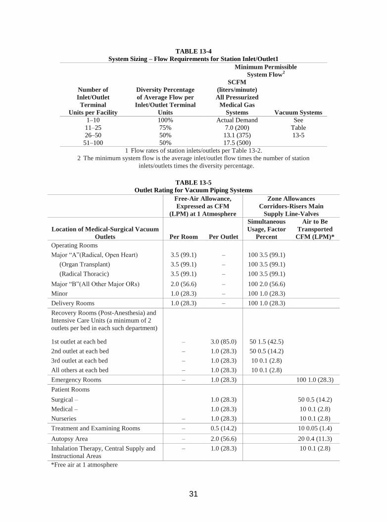
31
TABLE 13-4
System Sizing – Flow Requirements for Station Inlet/Outlet1
Number of
Inlet/Outlet
Terminal
Units per Facility
Diversity Percentage
of Average Flow per
Inlet/Outlet Terminal
Units
Minimum Permissible
System Flow2
SCFM
(liters/minute)
All Pressurized
Medical Gas
Systems Vacuum Systems
1–10 100% Actual Demand See
11–25 75% 7.0 (200) Table
26–50 50% 13.1 (375) 13-5
51–100 50% 17.5 (500)
1 Flow rates of station inlets/outlets per Table 13-2.
2 The minimum system flow is the average inlet/outlet flow times the number of station
inlets/outlets times the diversity percentage.
TABLE 13-5
Outlet Rating for Vacuum Piping Systems
Free-Air Allowance,
Expressed as CFM
(LPM) at 1 Atmosphere
Zone Allowances
Corridors-Risers Main
Supply Line-Valves
Location of Medical-Surgical Vacuum
Outlets Per Room Per Outlet
Simultaneous
Usage, Factor
Percent
Air to Be
Transported
CFM (LPM)*
Operating Rooms
Major “A”(Radical, Open Heart) 3.5 (99.1) – 100 3.5 (99.1)
(Organ Transplant) 3.5 (99.1) – 100 3.5 (99.1)
(Radical Thoracic) 3.5 (99.1) – 100 3.5 (99.1)
Major “B”(All Other Major ORs) 2.0 (56.6) – 100 2.0 (56.6)
Minor 1.0 (28.3) – 100 1.0 (28.3)
Delivery Rooms 1.0 (28.3) – 100 1.0 (28.3)
Recovery Rooms (Post-Anesthesia) and
Intensive Care Units (a minimum of 2
outlets per bed in each such department)
1st outlet at each bed – 3.0 (85.0) 50 1.5 (42.5)
2nd outlet at each bed – 1.0 (28.3) 50 0.5 (14.2)
3rd outlet at each bed – 1.0 (28.3) 10 0.1 (2.8)
All others at each bed – 1.0 (28.3) 10 0.1 (2.8)
Emergency Rooms – 1.0 (28.3) 100 1.0 (28.3)
Patient Rooms
Surgical – 1.0 (28.3) 50 0.5 (14.2)
Medical – 1.0 (28.3) 10 0.1 (2.8)
Nurseries – 1.0 (28.3) 10 0.1 (2.8)
Treatment and Examining Rooms – 0.5 (14.2) 10 0.05 (1.4)
Autopsy Area – 2.0 (56.6) 20 0.4 (11.3)
Inhalation Therapy, Central Supply and
Instructional Areas
– 1.0 (28.3) 10 0.1 (2.8)
*Free air at 1 atmosphere

32
TABLE 13-6
Size of Gas/Vacuum Piping
Maximum Delivery Capacity3 in SCFM (LPM)
Length of Piping in Feet (m)1
Medical
System
Gas
Pipe
Size
Inch2
100 (30) 250 (76) 500 (152) 750 (228) 1,000 (304)
Oxygen 1/2 15.0 (425) 10.6 (300) 7.4 (209) 5.9 (167) 5.1 (144)
3/4 40.0 (1,133) 28.3 (801) 19.6 (555) 15.7 (445) 13.3 (377)
1 50.0 (1,416) 50.0 (1,416) 40.2 (1,138) 32.2 (912) 27.7 (784)
1/2 15.0 (425) 9.5 (269) 6.5 (184) 5.3 (150) 4.5 (127)
Nitrous
Oxide
3/4 30.0 (849) 24.7 (699) 17.1 (484) 13.7 (388) 11.7 (331)
1 40.0 (1,113) 40.0 (1,133) 34.7 (983) 28.2 (7,98) 24.3 (688)
1/2 18.1 (512) 11.1 (314) 7.8 (221) 6.3 (177) 5.3 (151)
Medical
Air
3/4 40.0 (1,133) 29.9 (847) 21.0 (595) 16.5 (467) 14.1 (399)
1 50.0 (1,416) 50.0 (1,416) 42.1 (1,192) 35.8 (1,013) 29.2 (826)
1 22.8 (645) 13.7 (388) 9.5 (269) 7.6 (215) 6.5 (184)
Vacuum 1-1/4 40.1 (1,135) 24.5 (694) 16.7 (473) 13.3 (377) 11.2 (317)
1-1/2 63.7 (1,804) 38.9 (1,101) 26.8 (759) 21.1 (600) 17.9 (507)
2 132.7 (3,758) 81.4 (2,305) 56.0 (1,586) 45.0 (1,274) 38.3 (1,084)
1/2 25.0 (708) 25.0 (708) 25.0 (708) 23.8 (674) 20.6 (583)
Nitrogen 3/4 60.0 (1,699) 60.0 (1,699) 60.0 (1,699) 60.0 (1,699) 54.2 (1,535)
1 110.0 (3,115) 110.0 (3,115) 110.0 (3,115) 110.0 (3,115) 110.0 (3,115) 1 Length of piping includes a 30% allowance for fittings.
2 One-half inch (12.7 mm) diameter pipe is the minimum size allowed in medical gas systems.
3 Based on the following maximum pressure drops:
Oxygen, nitrous oxide, and medical air – 5 psig (10 in. Hg)
Vacuum – 1.96 psig (4 in. Hg)
Nitrogen – 20 psig (41 in. Hg)
TABLE 13-7
Maximum Pipe Support Spacing [NFPA 99:5.1.10.10.4.5 5.1.11.4.5]
Pipe Size Hanger Spacing
ft. mm
DN8 (NPS 1/4) (3/8 in. O.D.) 5 1,520
DN10 (NPS 3/8) (1/2 in. O.D.) 6 1,830
DN15 (NPS 1/2) (5/8 in. O.D.) 6 1,830
DN20 (NPS 3/4) (7/8 in. O.D.) 7 2,130
DN25 (NPS 1) (1-1/8 in. O.D.) 8 2,440
DN32 (NPS 1-1/4) (1-3/8 in. O.D.) 9 2,740
DN40 (NPS 1-1/2) (1-5/8 in. O.D.)
and larger 10 3,050
Vertical risers, all sizes
Every floor but not to exceed: 15 4,570