CHAPTER 12 HYDRONIC PIPING
4
CHAPTER 12 HYDRONIC PIPING SECTION 1201 GENERAL 1201.1 Scope. The provisions of this chapter shall govern the construction, installation, alteration and repair of hydronic piping systems. This chapter shall apply to hydronic piping systems that are parts of heating, ventilation and air-condi- tioning systems. Such piping systems shall include steam, hot water, chilled water, steam condensate and ground source heat pump loop systems. Potable cold and hot water distribu- tion systems shall be installed in accordance with the Florida Building Code, Plumbing. 1201.2 Pipe sizing. Piping for hydronic systems shall be sized for the demand of the system. SECTION 1202 MATERIAL 1202.1 Piping. Piping material shall conform to the stan- dards cited in this section. Exception: Embedded piping regulated by Section 1209. 1202.2 Used materials. Reused pipe, fittings, valves or other materials shall be clean and free of foreign materials and shall be approved by the code official for reuse. 12023 Material rating. Materials shall be rated for the operat- ing temperature and pressure of the hydronic system. Materials shall be suitable for the type of fluid in the hydronic system. 1202.4 Piping materials standards. Hydronic pipe shall conform to the standards listed in Table 1202.4. The exterior of the pipe shall be protected from corrosion and degradation. TABLE 1202.4 HYDRONIC PIPE MATERIAL Acrylonitrile butadiene styrene (ABS) plastic pipe, Brass pipe Brass tubing Copper or copper-alloy pipe Copper or copper-alloy tube (Type K, L or M) Chlorinated polyvinyl chloride (CPVC) plastic pipe Cross-linked polyethylene/aluminum/ cross-linked polyethylene (PEX-AL-PEX) pressure pipCSA Cross-linked polyethylene (PEX) tubing STANDARD (see Chapter 15) ASTM D1527; ASTM D 2282 ASTM B 43 ASTM B 135 ASTM B 42; ASTM B 302 ASTM B 75; ASTM B 88; ASTM B 251 ASTM D 2846; ASTM F 441; ASTM F 442 CAN/CSA-B-137.10 ASTM F 876; ASTM F 877 MATERIAL Lead pipe Polybutylene (PB) plastic pipe and tubing Polyvinyl chloride (PVC) plastic pipe Steel pipe Steel tubing STANDARD (see Chapter 15) FS WW-P-325B ASTM D 3309 ASTM D 1785; ASTM D 2241 ASTM A 53;ASTM A106; ASTM A 254 MATERIAL Bronze Copper and copper alloys Gray iron Malleable iron Plastic Steel STANDARD (see Chapter 15) ASME B 16.24 ASME B16.15; ASME B16.18; ASME B16.22; ASME B16.23; ASME B16.26; ASME B16.29 ASTM A 126 ASTM B 16.3 ASTM D 2466; ASTM D 2467; ASTM D 2468; ASTM F 438; ASTM F 442; ASTM F 439; ASTM F 877 ASME B16.5; ASME B16.9; ASME B16.ll; ASME B16.28; ASTM A 420 TABLE 1202.4—(continued) HYDRONIC PIPE 1202.5 Pipe fittings. Hydronic pipe fittings shall be approved for installation with the piping materials to be installed, and shall conform to the respective pipe standards or to the standards listed in Table 1202.5. TABLE 1202.5 HYDRONIC PIPE FITTINGS 1202.6 Valves. Valves shall be constructed of materials that are compatible with the type of piping material and fluids in the system. Valves shall be rated for the temperatures and pressures of the systems in which the valves are installed. 1202.7 Flexible connectors, expansion and vibration com- pensators. Flexible connectors, expansion and vibration con- trol devices and fittings shall be of an approved type. SECTION 1203 JOINTS AND CONNECTIONS 1203.1 Approval. Joints and connections shall be of an approved type. Joints and connections shall be tight for the pressure of the hydronic system. 1203.1.1 Joints between different piping materials. Joints between different piping materials shall be made with approved adapter fittings. Joints between different metallic piping materials shall be made with approved dielectric fittings or brass converter fittings. FLORIDA BUILDING CODE — MECHANICAL 12.1
Transcript of CHAPTER 12 HYDRONIC PIPING
CHAPTER 12 HYDRONIC PIPING
SECTION 1201 GENERAL
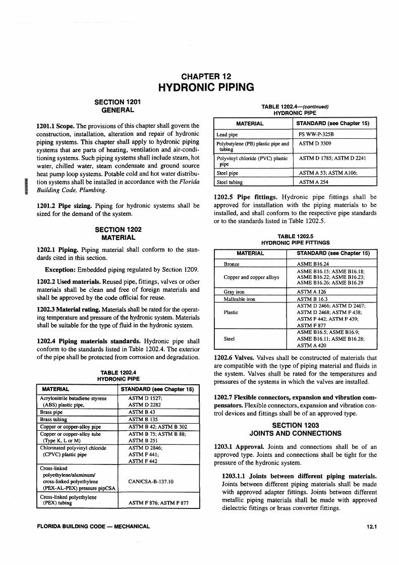
1201.1 Scope. The provisions of this chapter shall govern the construction, installation, alteration and repair of hydronic piping systems. This chapter shall apply to hydronic piping systems that are parts of heating, ventilation and air-conditioning systems. Such piping systems shall include steam, hot water, chilled water, steam condensate and ground source heat pump loop systems. Potable cold and hot water distribution systems shall be installed in accordance with the Florida Building Code, Plumbing.
1201.2 Pipe sizing. Piping for hydronic systems shall be sized for the demand of the system.
SECTION 1202 MATERIAL
1202.1 Piping. Piping material shall conform to the standards cited in this section.
Exception: Embedded piping regulated by Section 1209.
1202.2 Used materials. Reused pipe, fittings, valves or other materials shall be clean and free of foreign materials and shall be approved by the code official for reuse.
12023 Material rating. Materials shall be rated for the operating temperature and pressure of the hydronic system. Materials shall be suitable for the type of fluid in the hydronic system.
1202.4 Piping materials standards. Hydronic pipe shall conform to the standards listed in Table 1202.4. The exterior of the pipe shall be protected from corrosion and degradation.
TABLE 1202.4 HYDRONIC PIPE
MATERIAL
Acrylonitrile butadiene styrene (ABS) plastic pipe,
Brass pipe Brass tubing Copper or copper-alloy pipe Copper or copper-alloy tube
(Type K, L or M) Chlorinated polyvinyl chloride
(CPVC) plastic pipe
Cross-linked polyethylene/aluminum/ cross-linked polyethylene (PEX-AL-PEX) pressure pipCSA
Cross-linked polyethylene (PEX) tubing
STANDARD (see Chapter 15)
ASTM D1527; ASTM D 2282 ASTM B 43 ASTM B 135 ASTM B 42; ASTM B 302 ASTM B 75; ASTM B 88; ASTM B 251 ASTM D 2846; ASTM F 441; ASTM F 442
CAN/CSA-B-137.10
ASTM F 876; ASTM F 877
MATERIAL
Lead pipe
Polybutylene (PB) plastic pipe and tubing
Polyvinyl chloride (PVC) plastic pipe
Steel pipe
Steel tubing
STANDARD (see Chapter 15)
FS WW-P-325B
ASTM D 3309
ASTM D 1785; ASTM D 2241
ASTM A 53;ASTM A106;
ASTM A 254
MATERIAL
Bronze
Copper and copper alloys
Gray iron Malleable iron
Plastic
Steel
STANDARD (see Chapter 15)
ASME B 16.24
ASME B16.15; ASME B16.18; ASME B16.22; ASME B16.23; ASME B16.26; ASME B16.29
ASTM A 126 ASTM B 16.3 ASTM D 2466; ASTM D 2467; ASTM D 2468; ASTM F 438; ASTM F 442; ASTM F 439; ASTM F 877 ASME B16.5; ASME B16.9; ASME B16.ll; ASME B16.28; ASTM A 420
TABLE 1202.4— (continued) HYDRONIC PIPE
1202.5 Pipe fittings. Hydronic pipe fittings shall be approved for installation with the piping materials to be installed, and shall conform to the respective pipe standards or to the standards listed in Table 1202.5.
TABLE 1202.5 HYDRONIC PIPE FITTINGS
1202.6 Valves. Valves shall be constructed of materials that are compatible with the type of piping material and fluids in the system. Valves shall be rated for the temperatures and pressures of the systems in which the valves are installed.
1202.7 Flexible connectors, expansion and vibration compensators. Flexible connectors, expansion and vibration control devices and fittings shall be of an approved type.
SECTION 1203 JOINTS AND CONNECTIONS
1203.1 Approval. Joints and connections shall be of an approved type. Joints and connections shall be tight for the pressure of the hydronic system.
1203.1.1 Joints between different piping materials. Joints between different piping materials shall be made with approved adapter fittings. Joints between different metallic piping materials shall be made with approved dielectric fittings or brass converter fittings.
FLORIDA BUILDING CODE — MECHANICAL 12.1
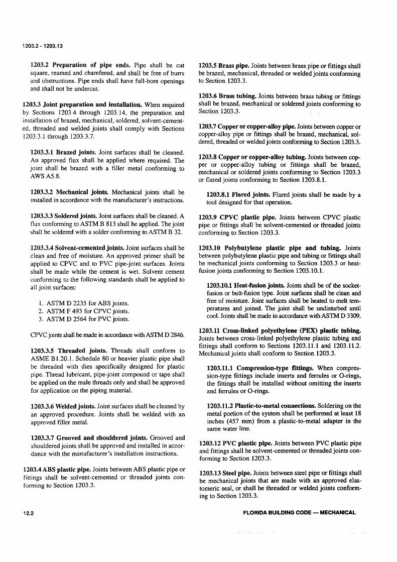
1203.2 Preparation of pipe ends. Pipe shall be cut square, reamed and chamfered, and shall be free of burrs and obstructions. Pipe ends shall have full-bore openings and shall not be undercut.
1203.3 Joint preparation and installation. When required by Sections 1203.4 through 1203.14, the preparation and installation of brazed, mechanical, soldered, solvent-cemented, threaded and welded joints shall comply with Sections 1203.3.1 through 1203.3.7.
1203.3.1 Brazed joints. Joint surfaces shall be cleaned. An approved flux shall be applied where required. The joint shall be brazed with a filler metal conforming to AWS A5.8.
1203.3.2 Mechanical joints. Mechanical joints shall be installed in accordance with the manufacturer's instructions.
1203.3.3 Soldered joints. Joint surfaces shall be cleaned. A flux conforming to ASTM B 813 shall be applied. The joint shall be soldered with a solder conforming to ASTM B 32.
1203.3.4 Solvent-cemented joints. Joint surfaces shall be clean and free of moisture. An approved primer shall be applied to CPVC and to PVC pipe-joint surfaces. Joints shall be made while the cement is wet. Solvent cement conforming to the following standards shall be applied to all joint surfaces:
1. ASTM D 2235 for ABS joints. 2. ASTM F 493 for CPVC joints. 3. ASTM D 2564 for PVC joints.
CPVC joints shall be made in accordance with ASTM D 2846.
1203.3.5 Threaded joints. Threads shall conform to ASME B 1.20.1. Schedule 80 or heavier plastic pipe shall be threaded with dies specifically designed for plastic pipe. Thread lubricant, pipe-joint compound or tape shall be applied on the male threads only and shall be approved for application on the piping material.
1203.3.6 Welded joints. Joint surfaces shall be cleaned by an approved procedure. Joints shall be welded with an approved filler metal.
1203.3.7 Grooved and shouldered joints. Grooved and shouldered joints shall be approved and installed in accordance with the manufacturer's installation instructions.
1203.4 ABS plastic pipe. Joints between ABS plastic pipe or fittings shall be solvent-cemented or threaded joints conforming to Section 1203.3.
1203.5 Brass pipe. Joints between brass pipe or fittings shall be brazed, mechanical, threaded or welded joints conforming to Section 1203.3.
1203.6 Brass tubing. Joints between brass tubing or fittings shall be brazed, mechanical or soldered joints conforming to Section 1203.3.
1203.7 Copper or copper-alloy pipe. Joints between copper or copper-alloy pipe or fittings shall be brazed, mechanical, soldered, threaded or welded joints conforming to Section 1203.3.
1203.8 Copper or copper-alloy tubing. Joints between copper or copper-alloy tubing or fittings shall be brazed, mechanical or soldered joints conforming to Section 1203.3 or flared joints conforming to Section 1203.8.1.
1203.8.1 Flared joints. Flared joints shall be made by a tool designed for that operation.
1203.9 CPVC plastic pipe. Joints between CPVC plastic pipe or fittings shall be solvent-cemented or threaded joints conforming to Section 1203.3.
1203.10 Polybutylene plastic pipe and tubing. Joints between polybutylene plastic pipe and tubing or fittings shall be mechanical joints conforming to Section 1203.3 or heat-fusion joints conforming to Section 1203.10.1.
1203.10.1 Heat-fusion joints. Joints shall be of the socket-fusion or butt-fusion type. Joint surfaces shall be clean and free of moisture. Joint surfaces shall be heated to melt temperatures and joined. The joint shall be undisturbed until cool. Joints shall be made in accordance with ASTM D 3309.
1203.11 Cross-linked polyethylene (PEX) plastic tubing. Joints between cross-linked polyethylene plastic tubing and fittings shall conform to Sections 1203.11.1 and 1203.11.2. Mechanical joints shall conform to Section 1203.3.
1203.11.1 Compression-type fittings. When compression-type fittings include inserts and ferrules or O-rings, the fittings shall be installed without omitting the inserts and ferrules or O-rings.
1203.11.2 Plastic-to-metal connections. Soldering on the metal portion of the system shall be performed at least 18 inches (457 mm) from a plastic-to-metal adapter in the same water line.
1203.12 PVC plastic pipe. Joints between PVC plastic pipe and fittings shall be solvent-cemented or threaded joints conforming to Section 1203.3.
1203.13 Steel pipe. Joints between steel pipe or fittings shall be mechanical joints that are made with an approved elas-tomeric seal, or shall be threaded or welded joints conforming to Section 1203.3.
12.2 FLORIDA BUILDING CODE — MECHANICAL
1203.2-1203.13

1203.14 Steel tubing. Joints between steel tubing or fittings shall be mechanical or welded joints conforming to Section 1203.3.
SECTION 1204 PIPE INSULATION
1204.1 Insulation characteristics. Pipe insulation installed in buildings shall conform to the requirements of the Chapter 13 of the Florida Building Code, Building, shall be tested in accordance with ASTM E 84 and shall have a maximum flame spread index of 25 and a smoke-developed index not exceeding 450. Insulation installed in an air plenum shall comply with Section 602.2.1.
Exception: The maximum flame spread index and smoke-developed index shall not apply to one- and two-family dwellings.
1204.2 Required thickness. Hydronic piping shall be insulated to the thickness required by Chapter 13 of the Florida Building Code, Building.
SECTION 1205 VALVES
1205.1 Where required. Shutoff valves shall be installed in hydronic piping systems in the locations indicated in Sections 1205.1.1 through 1205.1.6.
1205.1.1 Heat exchangers. Shutoff valves shall be installed on the supply and return side of a heat exchanger.
Exception: Shutoff valves shall not be required when heat exchangers are integral with a boiler; or are a component of a manufacturer's boiler and heat exchanger packaged unit and are capable of being isolated from the hydronic system by the supply and return valves required by Section 1005.1.
1205.1.2 Central systems. Shutoff valves shall be installed on the building supply and return of a central utility system.
1205.1.3 Pressure vessels. Shutoff valves shall be installed on the connection to any pressure vessel.
1205.1.4 Pressure-reducing valves. Shutoff valves shall be installed on both sides of a pressure-reducing valve.
1205.1.5 Equipment and appliances. Shutoff valves shall be installed on connections to mechanical equipment and appliances. This requirement does not apply to components of a hydronic system such as pumps, air separators, metering devices and similar equipment.
1205.1.6 Expansion tanks. Shutoff valves shall be installed at connections to nondiaphragm-type expansion tanks.
1203.14 -1206.8
1205.2 Reduced pressure. A pressure relief valve shall be installed on the low-pressure side of a hydronic piping system that has been reduced in pressure. The relief valve shall be set at the maximum pressure of the system design. The valve shall be installed in accordance with Section 1006.
SECTION 1206 PIPING INSTALLATION
1206.1 General. Piping, valves, fittings and connections shall be installed in accordance with the conditions of approval.
1206.1.1 Prohibited tee applications. Fluid in the supply side of a hydronic system shall not enter a tee fitting through the branch opening.
1206.2 System drain down. Hydronic piping systems shall be designed and installed to permit the system to be drained. Where the system drains to the plumbing drainage system, the installation shall conform to the requirements of the Florida Building Code, Plumbing.
1206.3 Protection of potable water. The potable water system shall be protected from backflow in accordance with the Florida Building Code, Plumbing.
1206.4 Pipe penetrations. Openings for pipe penetrations in walls, floors or ceilings shall be larger than the penetrating pipe. Openings through concrete or masonry building elements shall be sleeved. The annular space surrounding pipe penetrations shall be protected in accordance with the Florida Building Code, Building.
1206.5 Clearance to combustibles. A pipe in a hydronic piping system in which the exterior temperature exceeds 250°F (121°C) shall have a minimum clearance of 1 inch (25.4 mm) to combustible materials.
1206.6 Contact with building material. A hydronic piping system shall not be in direct contact with building materials that cause the piping material to degrade or corrode, or that interfere with the operation of the system.
1206.7 Water hammer. The flow velocity of the hydronic piping system shall be controlled to reduce the possibility of water hammer. Where a quick-closing valve creates water hammer, an approved water-hammer arrestor shall be installed. The arrestor shall be located within a range as specified by the manufacturer of the quick-closing valve.
1206.8 Steam piping pitch. Steam piping shall be installed to drain to the boiler or the steam trap. Steam systems shall not have drip pockets that reduce the capacity of the steam piping.
FLORIDA BUILDING CODE — MECHANICAL 12.3

1206.9-1209.4
1206.9 Strains and stresses. Piping shall be installed so as to prevent detrimental strains and stresses in the pipe. Provisions shall be made to protect piping from damage resulting from expansion, contraction and structural settlement. Piping shall be installed so as to avoid structural stresses or strains within building components.
1206.9.1 Flood hazard. Piping located in a flood-hazard zone or high-hazard zone shall be capable of resisting hydrostatic and hydrodynamic loads and stresses, including the effects of buoyancy, during the occurrence of flooding to the base flood elevation.
1206.10 Pipe support. Pipe shall be supported in accordance with Section 305.
1206.11 Condensation. Provisions shall be made to prevent the formation of condensation on the exterior of piping.
SECTION 1207 TRANSFER FLUID
1207.1 Flash point. The flash point of transfer fluid in a hydronic piping system shall be a minimum of 50°F (28°C) above the maximum system operating temperature.
1207.2 Makeup water. The transfer fluid shall be compatible with the makeup water supplied to the system.
SECTION 1208 TESTS
1208.1 General. Hydronic piping systems shall be tested hydrostatically at one and one-half times the maximum system design pressure, but not less than 100 psi (689 kPa).
SECTION 1209 EMBEDDED PIPING
1209.1 Materials. Piping for heating panels shall be standard-weight steel pipe, Type L copper tubing, polybutylene or other approved plastic pipe or tubing rated at 100 psi (689 kPa)at 180°F(82°C).
1209.2 Pressurizing during installation. Piping to be embedded in concrete shall be pressure tested prior to pouring concrete. During pouring, the pipe shall be maintained at the proposed operating pressure.
1209.3 Embedded joints. Joints of pipe or tubing that are embedded in a portion of the building, such as concrete or plaster, shall be in accordance with the requirements of Sections 1209.3.1 through 1209.3.3.
1209.3.1 Steel pipe joints. Steel pipe shall be welded by electrical arc or oxygen/acetylene method.
1209.3.2 Copper tubing joints. Copper tubing shall be joined by brazing with filler metals having a melting point of not less than 1,000°F (538°C).
1209.3.3 Polybutylene joints. Polybutylene pipe and tubing shall be installed in continuous lengths or shall be joined by heat fusion in accordance with Section 1203.10.1.
1209.4 Not embedded related piping. Joints of other piping in cavities or running exposed shall be joined by approved methods in accordance with manufacturer's installation instructions and related sections of this code.
12.4 FLORIDA BUILDING CODE — MECHANICAL