Chapter 12 FB-PLC Communication - SEA Praha · Chapter 12 FB-PLC Communication The main unit of MC...
20
Chapter 12 FB-PLC Communication The main unit of MC model of FB-PLC has three built-in communication ports with the interface of HCMOS, RS-232 and RS-485; that share the 15-pin D-sub female connector located on the left side of the main unit. Please refer to chapter 1 of “Hardware Manual” for the signal distribution details. FB-PLC also provides many communication converters (cables) for the conversion between the interface of RS-232 and RS-485, or between the interface of HCMOS and RS-232 or RS-485. By matching with suitable communication converters, the three built-in FB-PLC communication ports can be converted into one of the three additional configurations, i.e. two RS-232 plus one RS-485, one RS-232 plus two RS-485 or three RS-485. Note : The main unit of MA model only has one communication port with HCMOS interface. 12.1 Functions and Applications of FB-PLC Communication Ports FB-PLC not only has three different hardware interfaces but also has three types of software interfaces. The table below shows the types of software interfaces that the three FB-PLC communication ports can be defined: Communication Port Type Available Software Interface port0 port1 port2 Note Standard Interface ○ ○ ○ Controlled by the CPU via the "Standard Communication Driver of FATEK” Modem interface ○ Controlled by the CPU via the "MODEM Interface Driver" and “Standard Communication Driver of FATEK” Ladder Program Control Interface ○ ○ The user controls these ports via ladder diagram program Setting Method of Interface - By SW1 Auto Please refer to Section 12.6.3 • Standard Interface: This type of interface can be set in port0~port2 (only this type of interface is allowed in port0) and is called “Standard Interface” due to the fact that the port is controlled by the FB-PLC Standard Communication Driver (applying “FB-PLC Communication Protocol”). It is necessary to conform to “FB-PLC Communication Protocol” before connection with “Standard Interface” can be made for communication. This is the system default. • Modem interface: This type of interface can only be selected in port1 that is controlled by the FB-PLC built-in “MODEM Interface Driver” for receiving phone calls or dialing. After connecting, control will be passed to “Standard Communication Driver”; all operations will be the same as for “Standard Interface” afterwards. • Ladder Program Control Interface: This type of interface can be selected in port1 or port2. The port under this type of interface is controlled by the handy instructions of ladder program (such as FUN94, FUN 96 and FUN97). Thus, the user may control these communication ports for various communication applications via the ladder program. The following sections will describe the functions and applications of the three FB-PLC communication ports in each of the three different types of software interface with or without communication converters (cables) being added (called the “Basic Application” or the “Derived Application”, respectively). 12-1
Transcript of Chapter 12 FB-PLC Communication - SEA Praha · Chapter 12 FB-PLC Communication The main unit of MC...

Chapter 12 FB-PLC Communication
The main unit of MC model of FB-PLC has three built-in communication ports with the interface of HCMOS, RS-232 and RS-485; that share the 15-pin D-sub female connector located on the left side of the main unit. Please refer to chapter 1 of “Hardware Manual” for the signal distribution details. FB-PLC also provides many communication converters (cables) for the conversion between the interface of RS-232 and RS-485, or between the interface of HCMOS and RS-232 or RS-485. By matching with suitable communication converters, the three built-in FB-PLC communication ports can be converted into one of the three additional configurations, i.e. two RS-232 plus one RS-485, one RS-232 plus two RS-485 or three RS-485.
Note : The main unit of MA model only has one communication port with HCMOS interface.
12.1 Functions and Applications of FB-PLC Communication Ports
FB-PLC not only has three different hardware interfaces but also has three types of software interfaces. The table below shows the types of software interfaces that the three FB-PLC communication ports can be defined:
Communication Port Type Available Software Interface port0 port1 port2
Note
Standard Interface ○ ○ ○ Controlled by the CPU via the "Standard Communication Driver of FATEK”
Modem interface ○ Controlled by the CPU via the "MODEM Interface Driver" and “Standard Communication Driver of FATEK”
Ladder Program Control Interface ○ ○ The user controls these ports via ladder diagram program
Setting Method of Interface - By SW1 Auto Please refer to Section 12.6.3
• Standard Interface: This type of interface can be set in port0~port2 (only this type of interface is allowed in port0) and is called “Standard Interface” due to the fact that the port is controlled by the FB-PLC Standard Communication Driver (applying “FB-PLC Communication Protocol”). It is necessary to conform to “FB-PLC Communication Protocol” before connection with “Standard Interface” can be made for communication. This is the system default.
• Modem interface: This type of interface can only be selected in port1 that is controlled by the FB-PLC built-in “MODEM Interface Driver” for receiving phone calls or dialing. After connecting, control will be passed to “Standard Communication Driver”; all operations will be the same as for “Standard Interface” afterwards.
• Ladder Program Control Interface: This type of interface can be selected in port1 or port2. The port under this type of interface is controlled by the handy instructions of ladder program (such as FUN94, FUN 96 and FUN97). Thus, the user may control these communication ports for various communication applications via the ladder program.
The following sections will describe the functions and applications of the three FB-PLC communication ports in each of the three different types of software interface with or without communication converters (cables) being added (called the “Basic Application” or the “Derived Application”, respectively).
12-1

12.1.1 Communication Port 0 (port0): HCMOS (5V) Serial Interface
Function Specification
• Communication parameters: Baud Rate:9600 bps (Default; 19200,38400 also allowed) Data Length:7 Bits (Fixed) Parity:Even (Fixed) Stop Bit:1 Bit (Fixed) • Communication distance ≤ 2 meters
Basic Application
The port0 has the hardware interface of HCMOS and the software interface of “Standard Interface” (i.e. applying “FB-PLC Communication Protocol”) and which is mainly used to connect the FP-07 handheld programmer.
Derived Application
By adding FB-232P0-××-×× cable with converter to convert the hardware interface of port0 into RS-232C interface: For connection with peripherals having RS-232C interface, such as PC, MMI, SCADA,….
By adding FB-485P0 or FB-232P0-××-×× and FB-485 to convert port0 into RS-485 interface: For connection with peripherals having RS-485 interface, such as PC, MMI, SCADA,…. By this way, it may be connected to the FB-PLC CPU Link Network.
12.1.2 Communication Port 1 (port1): RS-232C Serial Interface
Function Specification
• The signal specification meets the EIA RS-232C standard and the communication parameters are adjustable. The maximum communication speed can reach 38.4Kbps. The default communication parameters are as bellow: Baud Rate:9600 bps ; Data Length:7 Bits ; Parity:Even ; Stop Bit:1 Bit
Basic Application
The following three types of software interfaces can be selected through SW1 (2-pin DIP switch) on the main unit: (Please refer to Section 12.6.3 for setting methods)
RS-232 Standard Interface:
For connection with peripherals having RS-232 interface, such as PC, MMI, SCADA, ….
RS-232 Modem Interface:
It will provide the remote diagnostics and trouble debugging or remote data collection or alarm and fault report via the Modem interface.
RS-232 Ladder Program Control Interface:
The user can control port1 through ladder diagram program, e.g. FUN94 (ASCWR) instruction is to take over the control of port1 and can be connected with the printer having RS-232 hardware interface for report printing; FUN97 (LINK1) instruction is to take over the control of port1 to make point to point connection between FB-PLC or intelligent ASCII peripherals.
12-2

Derived Application
After adding a RS-232↔RS-485 converter (FB-485) to port1, port1 can be converted from RS-232 interface to RS-485 interface and can make multidrop connections. The following two applications are derived:
The FB-485 converter is added under the "Standard Interface" to convert port1 to “RS-485 Standard Interface” : For connection with peripherals having RS-485 interface, such as PC, MMI, SCADA,…; or it may be connected to the FB-PLC CPU Link network.
By adding the FB-485 converter under the "Ladder Diagram Control Interface", port1 can be converted into “RS-485 Ladder Program Control Interface” : The applications described as bellow: • By FUN97:MD0 instruction, it can be as the master of FB-PLC CPU Link Network. • By FUN97:MD1 instruction, it can be as the ASCII sender and connect with the intelligent peripherals, such as other PLC, servo driver,temperature controller,invertor…. • By FUN97:MD2 instruction, it can be as the ASCII receiver and connect with intelligent peripherals, such as magnetic card reader, barcode reader and electronic weighing scale….
12.1.3 Communication Port 2 (port2): RS-485 Serial Interface
Function Specification
• The signal specification meets the EIA RS-485 standard and the communication parameters are adjustable. The maximum communication speed can reach 614.4Kbps. This port with the ability for real-time distributed control (by FUN96:MD3, high speed CPU link ). The default communication parameters are as bellow: Baud Rate:9600 bps ; Data Length:7 Bits ; Parity:Even ; Stop Bit:1 Bit
Basic Application
The port2 software interface includes “RS-485 Standard Interface” and “RS-485 Ladder Diagram Control Interface”. The type of the software interface is determined by the user’s ladder program. This means that when the instruction FUN96 (LINK2) appears in the ladder program and being executed, the CPU will automatically set the interface type of port2 as “RS-485 Ladder Program Control Interface” or, else, “RS-485 Standard Interface”. Details are described as below:
The “RS-485 Standard Interface”: For connection with peripherals having RS-485 interface, such as PC, MMI, SCADA,…; or it may be connected to the FB-PLC CPU Link network.
The “RS-485 Ladder Program Control Interface”: The applications described as bellow: • By FUN96:MD0 instruction, it can be as the master of FB-PLC CPU Link Network. • By FUN96:MD3 instruction, it can be as the master of FB-PLC High Speed CPU Link Network. • By FUN96:MD1 instruction, it can be as the ASCII sender and connect with the intelligent peripherals, such as other PLC, servo driver, temperature controller, invertor…. • By FUN96:MD2 instruction, it can be as the ASCII receiver and connect with intelligent peripherals, such as magnetic card reader, barcode reader and electronic weighing scale….
12-3

12.2 FB-DTBR Communication Distributor
As described previously, the three built-in communication ports of the MC main unit share the 15-pin D-sub female connector located on the left side of the main unit. FB-DTBR is the signals distributor, which is connected to the 15-pin D-sub and distributes the interface signals to the three independent communication connector for easy connection. Please refer to charpter 1 of “Hardware Manual” for the connection between FB-DTBR and the PLC main unit. The diagram below shows the specification and internal circuit of FB-DTBR.
1
2
3
4
5
6
7
815
14
13
12
11
10
9
D + D FG
(Port 2)RS-485
RS-232
RS-232
HCMOS
RS-232(Port 1)
1
2
3
4
59
8
7
6
1
2
3
4
59
8
7
6
4
5
6
7
815
14
13
12
1
2
311
10
9
(Port 1)
(Port 0)
(Port 0)
Vcc
G
HCMOS
RS-232
RXD
TXDCTS
+
RTS
SG
SG
RXD
TXD
15PD-subMale
connector
Connect to FATEK PLC main unit
Converter
Terminal block
D-subFemale connector
D-subFemale connector
D-subFemale connector
FB-DTBR internal structure
ETHERNET
(Port 1)
(Port 0)HCMOS
+
(Port 2)
RS-232
(Port 0)RS-232
(Port 1)
(Port 2)or
RS-485
14
1
11
10
9
12
13
4
2
3
5
6
R
THE
E
158
7
6
7
9
83
2
1
4
5
8
6
7
1
2
3
95
4
3 OGnd2 S
VccS
2
RCM
H
N SS
VccTE
832 5
2 4
Gnd R R
FGD + D
DB-15M
6
11
9
102
1
3
12
13
4
5
15
147
8
12.3 FB-DTBR-E Communication Distributor With Ethernet interface
FB-DTBR-E internal structure
12-4

12.4 Communication Connectors and Communication Converters of FB-PLC
The FB-DTBR has already distributed 3 communication ports to a terminal base and 2 standard 9Pin D-Sub connectors. User may use standard connecting cable available on the market for connection. Given that the pin layout of 15Pin D-sub of FB-PLC is not standard and no commercial connecting cables are available, users who do not apply FB-DTBR may use FB-PLC communication connectors or cables of different specs provided by FATEK. To meet various interface requirements, there are also communication connector or cable with signal level conversion, which we call communication converter or communication cable with converter. The communication connector (or cable) and communication converter (or cable with converter) are identical in appearance. But to make the distinction between them easier, all PVC-coated communication connectors (or cables) are cream color (the same color as the shell of main unit), while converters (or cables with converters) are in dark gray color.
12.4.1 Communication Connectors/Cables/Converters/Cables-with-converters
Type Product No. Spec Description Color
FB-MOSP0-MD-150 Connecting cable that connects Main Unit and FP-07
FB-232P1-9M-150 Communication cable that derives from port1 and connects to 9Pin D-sub male; cable length is 150 cm.
FB-232P1-9F-150 Communication cable that derives from port1 and connects to 9Pin D-sub female; cable length is 150 cm.
FB-232P1-25M-150 Communication cable that derives from port1 and connects to 25Pin D-sub male; cable length is 150 cm.
FB-232P1-25F-150 Communication cable that derives from port1 and connects to 25Pin D-sub female; cable length is 150 cm.
FB-485P2 Connector that derives from port2 to 3Pin terminal
Cream (same as that of main unit)
Connector or
Cable
FB-3EXT-15 Flat cable with 3 extended 15Pin D-sub that transparently derives from the main unit 15Pin D-sub; cable length is 15 cm.
FB-232P0-9M-150 Communication cable that derives from port0 and connects to 9Pin D-sub male (with the signal conversion of HCMOS↔RS-232)
FB-232P0-9F-150 Communication cable that derives from port0 and connects to 9Pin D-sub female (with the signal conversion of HCMOS↔RS-232)
FB-232P0-25M-150 Communication cable that derives from port0 and connects to 25Pin D-sub male (with the signal conversion of HCMOS↔RS-232)
FB-232P0-25F-150 Communication cable that derives from port0 and connects to 25Pin D-sub female (with the signal conversion of HCMOS↔RS-232)
FB-485P0 Converter that derives from port0 and connects to 3Pin terminal (with the signal conversion of HCMOS↔RS-485)
Dark Gray Converter
or Cable with converter
FB-485 General purpose converter that converts RS-232↔RS422/RS485
When selecting from communication connector/cable/converter/cable-with-converter listed above, beware of the port (port0, 1 or 2), hardware interface spec(HCMOS, RS-232, RS-485), mechanical specs of connector (model, pin number, male, female) required. The " Numbering rules of communication connector/cable/converter/cable-with-converter " provided in the next section will help you make the accurate selection.
12-5

12.4.2 Numbering Rules of Communication Connector/Cable/Converter/Cable-with-converter
F B − 2 3 2 P 0 − 2 5 F −1 5 0
(output connector spec) (length)in cm F : Female connector M : Male connector MD : Mini-DIN 9 : 9Pin D-sub
The connector of FB-PLC connecting line or converter must be15Pin D-sub male connector (that of FB-PLC communication connector is 15Pin D-sub female connector)
25 : 25Pin D-sub P0 : port0(HCMOS)
Derives
((
• For product No. that doesn't indicate length, it means theor converter. For example, FB-485P0 is a connector type
• FB-485 is the stand alone general purpose converter fnumbered according to the numbering rules presented in
12.4.3 Internal connection of Communication Con
A: Communication Connector / Cable
FB-MOSP0-MD-150: The communication cable for connlength is 150 cm.
21
3 4 5
6 7 8
12
P1 : port1(RS-232) from P2 : port2(RS-485) MOS : HCMOS utput
→
)
O
signallevel )
re is no cab converter t
or the conv this section
nector/C
ecting main
-6
232 : RS-232 485 : RS-485
→
le in its outer appearance. It is called a connector hat converts 15Pin D-sub to 3Pin terminal.
ersion of RS-232↔RS-422/RS-485, which is not .
able/Converter/Cable-with-converter
unit and FP-07x ; the cable with cream color and
1
2
3
4
5
6
7
815
14
13
12
11
10
9
To PLC D-Sub Male

FB-232P1-9M-150/FB-232P1-9M-30: The communication cable with cream color and length is 150 / 30 cm.
1
2
3
4
59
8
7
61
2
3
4
5
6
7
815
14
13
12
11
10
9
CTS
RTS
TXD
RXD
TXD
RXD
SG
To PLC D-Sub Male
D-sub Male SG
FB-232P1-9F-150: The communication cable with cream color and length is 150 cm.
1
2
3
4
59
8
7
6 1
2
3
4
5
6
7
815
14
13
12
11
10
9TXDCTSRXDRTS
SG
TXD
CTS
RXD
RTS
SG
To PLC D-Sub Male
D-Sub Female
FB-232P1-25M-150: The communication cable with cream color and length is 150 cm.
1
2
3
4
5
6
7
815
14
13
12
11
10
9
6
7
8
9
10
11
12
1325
24
23
22
21
20
19
1
2
3
4
518
17
16
15
14TXD
CTS
RXD
RTS
SG
TXD
CTS
RXD
RTS
SG
To PLC D-Sub Male
D-Sub Male
12-7

FB-232P1-25F-150: The communication cable with cream color and length is 150 cm.
1
2
3
4
5
6
7
815
14
13
12
11
10
9
6
7
8
9
10
11
12
1325
24
23
22
21
20
19
1
2
3
4
518
17
16
15
14
TXD
RTS
RXD
CTS
SG
TXD
CTS
RXD
RTS
SG
D-Sub Female
To PLC D-Sub Male
FB-485P2: The communication connector with cream color.
1
2
3
4
5
6
7
815
14
13
12
11
10
9
D+D_
FG
To PLC D-Sub Male
3Pin Terminal
B: Communication Converter / Cable-with-converter
FB-232P0-9M-150: The communication cable (built in signal conversion) with dark gray color and length is 150 cm.
1
2
3
4
59
8
7
61
2
3
4
5
6
7
815
14
13
12
11
10
9
GVcc
TXD
RXD
SG
HCMOS
RS-232
To PLC D-Sub Male
D-Sub Male
12-8

FB-232P0-9F-150: The communication cable (built in signal conversion) with dark gray color and length is 150 cm.
1
2
3
4
59
8
7
61
2
3
4
5
6
7
815
14
13
12
11
10
9
GVcc
TXD
RXD
SG
HCMOS
RS-232
To PLC D-Sub Male
D-Sub Female
FB-232P0-25M-150: The communication cable (built in signal conversion) with dark gray color and length is 150 cm.
1
2
3
4
5
6
7
815
14
13
12
11
10
9
GVcc
6
7
8
9
10
11
12
1325
24
23
22
21
20
19
1
2
3
4
518
17
16
15
14TXD
RXD
SG
HCMOS
RS-232
To PLC D-Sub Male
D-Sub Male
FB-232P0-25F-150: The communication cable (built in signal conversion) with dark gray color and length is 150 cm.
1
2
3
4
5
6
7
815
14
13
12
11
10
9
GVcc
6
7
8
9
10
11
12
1325
24
23
22
21
20
19
1
2
3
4
518
17
16
15
14
TXD
RXD
SG
HCMOS
RS-232
To PLC D-Sub Male
D-Sub Female
12-9
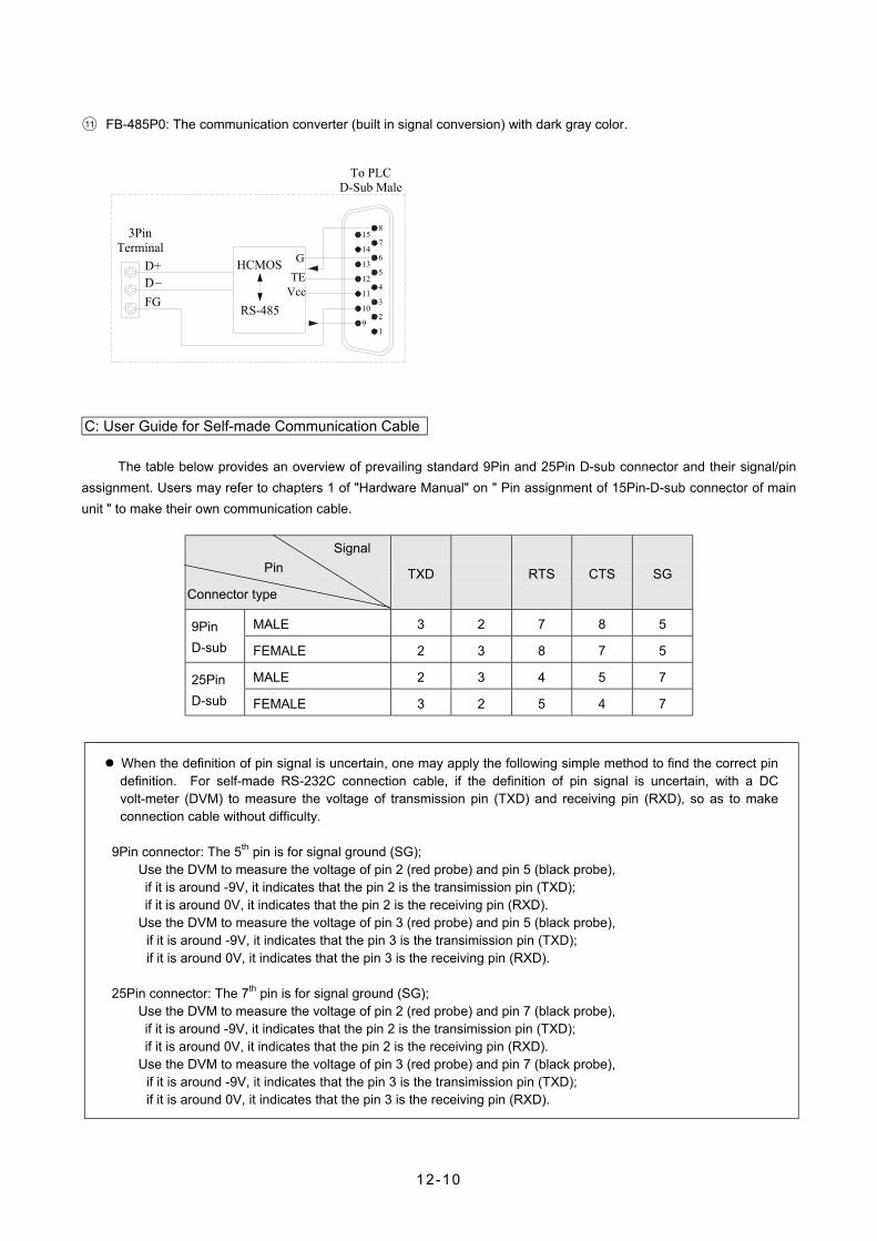
○11 FB-485P0: The communication converter (built in signal conversion) with dark gray color.
1
2
3
4
5
6
7
815
14
13
12
11
10
9
D+D_
FG
G
VccTE
HCMOS
RS-485
To PLC D-Sub Male
3Pin Terminal
C: User Guide for Self-made Communication Cable
The table below provides an overview of prevailing standard 9Pin and 25Pin D-sub connector and their signal/pin assignment. Users may refer to chapters 1 of "Hardware Manual" on " Pin assignment of 15Pin-D-sub connector of main unit " to make their own communication cable.
Signal Pin
Connector type TXD RXD RTS CTS SG
MALE 3 2 7 8 5 9Pin D-sub FEMALE 2 3 8 7 5
MALE 2 3 4 5 7 25Pin D-sub FEMALE 3 2 5 4 7
When the definition of pin signal is uncertain, one may apply the following simple method to find the correct pin definition. For self-made RS-232C connection cable, if the definition of pin signal is uncertain, with a DC volt-meter (DVM) to measure the voltage of transmission pin (TXD) and receiving pin (RXD), so as to make connection cable without difficulty.
9Pin connector: The 5th pin is for signal ground (SG); Use the DVM to measure the voltage of pin 2 (red probe) and pin 5 (black probe), if it is around -9V, it indicates that the pin 2 is the transimission pin (TXD); if it is around 0V, it indicates that the pin 2 is the receiving pin (RXD). Use the DVM to measure the voltage of pin 3 (red probe) and pin 5 (black probe),
if it is around -9V, it indicates that the pin 3 is the transimission pin (TXD); if it is around 0V, it indicates that the pin 3 is the receiving pin (RXD).
25Pin connector: The 7th pin is for signal ground (SG); Use the DVM to measure the voltage of pin 2 (red probe) and pin 7 (black probe), if it is around -9V, it indicates that the pin 2 is the transimission pin (TXD); if it is around 0V, it indicates that the pin 2 is the receiving pin (RXD). Use the DVM to measure the voltage of pin 3 (red probe) and pin 7 (black probe),
if it is around -9V, it indicates that the pin 3 is the transimission pin (TXD); if it is around 0V, it indicates that the pin 3 is the receiving pin (RXD).
12-10
12.5 How to Make Benefit via Communication Functions of FB-PLC
For the connection between FP-PLC and computers, intelligent peripherals and other PLCs, please refer to Section 2-2 of "Hardware Manual" on the diagram of "PLC and Peripheral Systems."
Although all 3 communication ports of FB-PLC can be converted to RS-232C or RS-485 interface, it's advised that "Basic Applications" described in Section 12.1 be followed in their actual application (i.e. without the addition of communication converter or cable-with-converter). This is the most economical way. The installation of communication converter or cable-with-converter may be considered when basic applications do not meet the needs.
Of the three communication ports, only port2 with the ability to make very fast real-time response (i.e. communication data are processed promptly after receiving/sending without being delayed by scan time). Its speed can reach up to 614.4Kbps and it adopts RTU code which is 100% faster than ASCII codes. Port0 and Port 1 use ASCII codes for communication with maximum speed at 38.4bps. Their received/sent communication data will not be processed until housekeeping following ladder program scanning. Thus data transmission is delayed by the duration of scan time. Thus in application, port2 may be reserved for "High-speed CPU Link Network" (via FUN96:MD3 instruction) to meet the requirement of distributed real-time control, while port0 and port1 are applied of data collection and monitoring in connection with intelligent peripherals, man-machine interface and graphic supervisoring.
12.6 Notifications in arrangement of RS-485 Communication
Of the three communication interfaces of FB-PLC, HCMOS and RS-232C interfaces can only make point to point connection, while RS-485 can have multdrop connections. For connection distance, RS-232 and RS-485 shall observe EIA standard, while HCMOS is limited to 2 meters.
The three communication interfaces should observe the basic principle of short connection and distant from high-noise source, because port0 and port1 are point to point connection with short connection length. The commercially available standard communication cable or that provided by FATEK will serve the purpose. But for high-speed RS-485 network which has a variety of issues to be dealt with, including high speed, long distance, great signal attenuation, multiple stations, plus poor grounding, noise interference, terminal impedance mismatching, and incorrect network topology, it is prone to have communication quality problem if the arrangement of connection is not carefully handled. Thus points to note in the hardware arrangement of RS-485 network are itemized in this section.
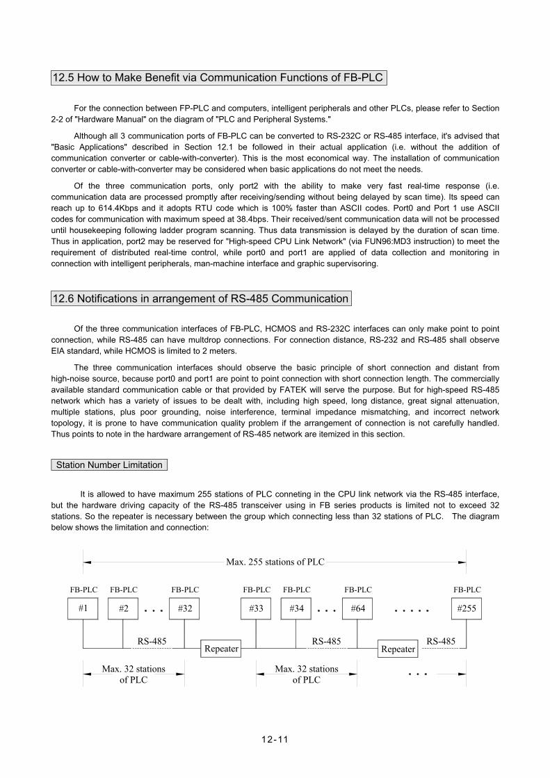
Station Number Limitation
It is allowed to have maximum 255 stations of PLC conneting in the CPU link network via the RS-485 interface, but the hardware driving capacity of the RS-485 transceiver using in FB series products is limited not to exceed 32 stations. So the repeater is necessary between the group which connecting less than 32 stations of PLC. The diagram below shows the limitation and connection:
Max. 32 stations of PLC
Max. 32 stationsof PLC
Max. 255 stations of PLC
FB-PLC FB-PLC FB-PLC FB-PLC FB-PLC FB-PLC FB-PLC
RS-485 RS-485RS-485
#1 #2 #32 #64#34#33 #255
Repeater Repeater
12-11
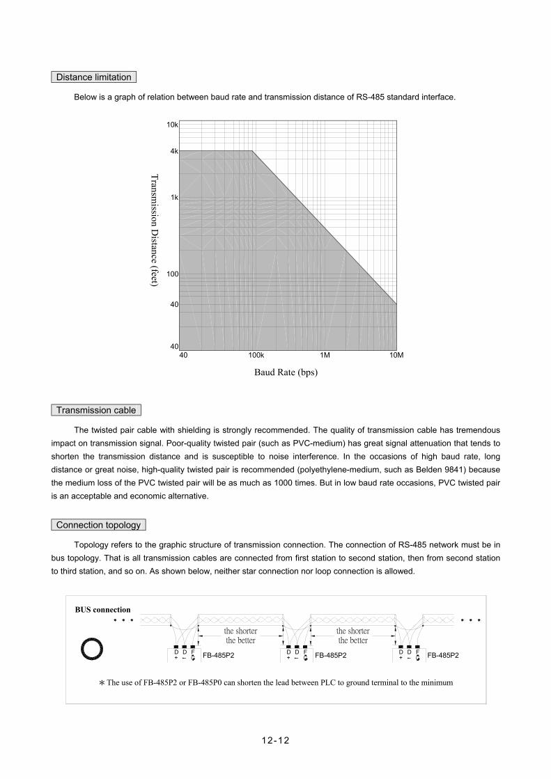
Distance limitation
Below is a graph of relation between baud rate and transmission distance of RS-485 standard interface.
10M1M100k4040
40
100
1k
4k
10k
Transm
ission Distance (feet)
Baud Rate (bps)
Transmission cable
The twisted pair cable with shielding is strongly recommended. The quality of transmission cable has tremendous impact on transmission signal. Poor-quality twisted pair (such as PVC-medium) has great signal attenuation that tends to shorten the transmission distance and is susceptible to noise interference. In the occasions of high baud rate, long distance or great noise, high-quality twisted pair is recommended (polyethylene-medium, such as Belden 9841) because the medium loss of the PVC twisted pair will be as much as 1000 times. But in low baud rate occasions, PVC twisted pair is an acceptable and economic alternative.
Connection topology
Topology refers to the graphic structure of transmission connection. The connection of RS-485 network must be in bus topology. That is all transmission cables are connected from first station to second station, then from second station to third station, and so on. As shown below, neither star connection nor loop connection is allowed.
*The use of FB-485P2 or FB-485P0 can shorten the lead between PLC to ground terminal to the minimum
the shorterthe better
FB-485P2D+D F FB-485P2FB-485P2DD
+F D
+D F
the shorterthe better
BUS connection
12-12

FB-485P2F+D D
+D D FB-485P2F
D+
DFB-485P2
F D+
D FStar connection
D
FB-485P2
F
D +
+D D
+D D
FB-485P2F
FB-485P2F
D
FB-485P2
F
D +
Loop connection
FG grounding
Althoug 2-wires twisted pair cable is enough for the connection of RS-485 network, but it is susceptible to noise interference and it must have the prerequisite that the ground potential difference (common-mode potential) between any two stations may not exceed the maximum allowable common-mode potential of transceiver IC of RS-485 interface. The allowable common-mode potential of FB-PLC should not exceed 7V. Otherwise, the RS-485 network won't be able to work normally.
Ecom≦ 7V
DD+
F D+
D F
Place A
Place B
The twisted pair with shielding is the best suggestion for the wiring of RS-485 network, regardless of the ground potential, that connects the FG of each station (as shown in "Connection Topology" above) via the shielding to eliminate common-mode potential and provide the shortest loop for transmission signals to effectively enhance noise immunity.
12-13

Terminator
All transmission circuits have their characteristic impedance due to the presence of various transmission cables(120Ω in the case of twisted pair). When signals are transmitted toward the end, reflection occurs when terminal impedance differs from the characteristic impedance that leads to distortion of waveform (depressed or raised). Such distortion is not obvious in short transmission. But as transmission cable increases in length, the distortion gets worse to the point that the transmission becomes inaccurate. In such event, terminators should be installed at left and right terminals of bus. Most of applications, the terminators are not necessary for FB-PLC, but when the communication is not good enough because of long distance and wiring of poor twisted pair, it may try to install the terminators at left and right terminals of bus (at D+ and D-) with resistor 120Ω(1/4w) as shown below. It is the last solution for FB-PLC to improve the communication quality that lets the jumper (JP2) be open of the main unit except the most left and right one's if the terminators are installed but still poor communication.
DD+ _ F
G_+ GDD F D
+D_ F
G +D _D
GF
(The end of left station) (The end of right station)
Actions against noise interference
If interference persists after RS-485 connections are arranged by the materials and rules recommended earlier, it's an indication that there are many noise sources in the vicinity of RS-485. Aside from keeping transmission cables as far from noise source as possible (such as electromagnetic valve, inverter, servo driver or other power devices), adding noise compressor to noise source is the most effective means of interference control. Please refer to Section 6.3.6 of "Hardware Manual" for related descriptions. Below is a diagram illustrating the methods of noise control over inverter, servo driver or other high noise-power equipment (the addition of X capacitor, Y capacitor or X+Y capacitor).
W
S
T
R
(add X capacitor)
C
R T R WS T R TS W
C
C
C
C
C
C
C
C
C
C C
S
(add Y capacitor) (add X+Y capacitor)
C = 0.22µf〜0.47µf/AC630V
12-14

Attention
• The wiring of communication network, the addition or removal of stations must be carried out under PLC power-off condition. Avoid power on operation, particularly when PLC is running. Otherwise, inaccurate output of PLC may result.
12.7 How to Use FB-PLC Communication Port The basic elements for communication equipments are that the hardware interface and mechanism
communication parameters software interface (communication protocol) of the sending/receiving equipment must be consistent. The same goes for PLC. PLC can communicate with PLC or other peripherals after the aforesaid three basic elements are satisfied.
12.7.1 Matching with Hardware Interface and Mechanism
The peripheral interface which FB-PLC can communicate with include FP-07 specific HCMOS interface and other two EIA standard interfaces(RS-232C and S-485). As described in Sections 12.2 and 12.3, you can select FB-DTBR communication distributor or communication connector/cable/converter/cable-with-converter to match up with any peripheral hardware interface and mechanism desired. Or it's not enough; you can make your own communication cables according to the instructions provided in Section 12.2.3.
12.7.2 Setting of Communication Parameters
Of the three (port0,1and 2) FB-PLC communication ports, the user may set the communication parameters. The default settings of these three ports are identical as below:
Baud Rate 9600 bps
Data Length 7 Bits
Parity Check Even
Stop Bits 1 Bit
D4
TXDor
RXD D0 D1 D2 D3 D5 D6 0/1 1 D0D7
~ ~
Idle Idle
7 or 8 bits
Frame
Start bit Stop bitParity bit Start bit
Start of next frame
Data format of asynchronous serial interface
A: Setting of port0 communication parameters
Port 0 communication parameters are set by the content of R4050 special register. R4050 is divided into high byte(B15〜B8)and low byte (B7 ~ B0). If the content of high byte is not equal to 55H, the communication parameter is the default, regardless of the content of low byte (The dfault of R4050 is 0000H). Only when the content of high byte of R4050 is equal to 55H will PLC set port0 communication parameters according to the definition of low byte; and only the baud rate of communication parameters may be changed as below:
While R4050 = 5500H, Baud Rate=19200 bps = 5501H, Baud Rate=9600 bps = 5502H, Baud Rate=38400 bps
The other parameters are fixed as follows: Data Length:7 Bits ; Parity Check:Even ; Stop Bit:1 Bit
12-15

B: Setting of port1 communication parameters
Port 1 communication parameters are set by the content of R4146 special register. R4146 is divided into high byte(B15〜B8)and low byte (B7 ~ B0). If the content of high byte is not equal to 55H, the communication parameters of port1 are automatically set at the default, regardless of the content of low byte (The default of R4146 is 0000H). Only when the content of high byte of R4146 is equal to 55H will PLC set port1 communication parameters according to the definition of low byte. The figure below shows the definition of low byte.
High byte Low byte
R4146 55H Communication parameters
B15 B8 B7 B0
0:Even Parity Odd/Even
parity 1:Odd Parity (Significant only when B5=1)
0:7 Bits
Data length 1:8 Bits
0:None Parity
Parity check 1:With Parity
0:1 Bit
Stop bits 1:2 Bits
B7 B6 B5 B4 B3 B2 B1 B0
R4146 Low Byte
〜
〜
0 0 0 0 1 1 1
B3 must be 0
1
Value Baud rate
0 0 0 19200 bps 0 1 1 9600 bps 1 0 2 4800 bps 1 1 3 2400 bps 0 0 4 1200 bps 0 1 5 600 bps 1 0 6 NA 1 1 7 38400 bps
12-16

C: Setting of port2 communication parameters
Port2 communication parameters can be adjusted according to the content of special register R4158 (not in High-speed CPU link) and R4161 (in High-speed CPU link) respectively. When high byte (B15 ~ B8) of R4158 or R4161 is 55H, the content of low byte (B7 ~ B0) determines the communication parameters. If the content of R4158 high byte is not 55H, the communication parameters are the default as mentioned before. If the content of R4161 high byte is not 55H, or data length is not 8 bits or baud rate is less than 38400bps, R4161 is automatically adjusted to default value 5565H (it means Baud rate:153600bps ; Data length: 8 Bits ; Parity check: Even ; Stop bit:1 Bit).
High byte Low byte
R4158 55H Communication parameters
(Default: 5521H; this register defines the communication parameters while not in High-speed CPU link)
B15 B8B7 B0 R4161 55H Communication
parameters (Default: 5565H; this register defines the communication parameters while in High-speed CPU link)
B15 B8B7 B0
0:Even Parity Odd/Even
parity 1:Odd Parity
0:7 Bits
Data length 1:8 Bits ※R4161 can only be 8Bits
0:None Parity
Parity check 1:With Parity
0:1 Bit
Stop bits 1:2 Bits
B7 B6 B5 B4 B3 B2 B1 B0
R4158 or
R4161
〜
〜
Value Baud rate 0 0 0 0 0 4800 bps 0 0 0 1 1 9600 bps 0 0 1 0 2 19200 bps 0 0 1 1 3 38400 bps 0 1 0 0 4 76800 bps 0 1 0 1 5 153600 bps 0 1 1 0 6 307200 bps 0 1 1 1 7 614400 bps 1 0 0 0 8 9000 bps 1 0 0 1 9 18000 bps 1 0 1 0 A 36000 bps 1 0 1 1 B 72000 bps 1 1 0 0 C 144000 bps 1 1 0 1 D 288000 bps 1 1 1 0 E 576000 bps
1 1 1 1 F 256000 bps
※ Baud Rate of R4161 must be ≥38400bps
※ Baud Rate of 256000bps is only valid for R4158, and the OS version must be FB-V3.43 or later
12-17

12.7.3 Setting of Software Interface
As described in Section 12.1, the communication ports of FB-PLC have three types of software interface. That of port0 is "Standard Interface" only; port2 has "Standard Interface" and "Ladder Diagram Control Interface", the type of interface is determined by the user's ladder program, it means that when the instruction FUN96 (LINK2) appears in the ladder program and being executed, the CPU will automatically set the interface type of port2 as “RS-485 Ladder Diagram Control Interface” or, else, “RS-485 Standard Interface”. Thus of the three communication ports, only port1 requires software interface setting which is achieved by the SW1 DIP switch on MC main unit.
OFF
ON
Bit1 Bit2
SW1
Switch position Software interface Bit1 Bit2
Description Remark
0 OFF OFF Designate port1 as "Standard Interface" Default setting
1 ON OFF Designate port1 as "Modem Interface"
2 OFF ON Port1 as "Ladder Program Control Interface"
3 ON ON Initialize the communication parameters of port0 by default
*The setting of this switch is valid only while power off
12.8 Description and Application of Software Interface
12.8.1 Standard Interface
Standard interface of communication port is controlled by the PLC system. The communication transactions are managed by the "Standard Communication Driver" (i.e. FB-PLC Communication Protocol). Any access to the port must comply with the format of said protocol before PLC responds, including start of text, station number, command code, text body, error-check code, end of text. For details, please refer to "FB-PLC Communication Protocol". FP-07, Proladder and many MMI and graphic supervisoring softwares have the communication drivers that comply with this protocol. When hardware interface and communication parameters are conforming, PLC may communicate with these peripherals metioned above via the "Standard Interface" communication port.
12.8.2 Modem Interface
This type of interface can only be selected in port1. Although CPU still manages the communication transactions of port1 by "Standard Communication Driver", it has to go through modem, for dialing or receiving. Prior to the initiation of communication, port control is managed by "Modem Interface Driver" and PLC cannot be accessed. Once the connection between the modems are successful, port control is turned over to "Standard Communication Driver" and port1 enters into "Standard Interface". This section will describe the operation of modem connection for active dialing and passive receiving.
Under modem interface, MC main unit can, according to the setting of phone number registers (R4140 ~ R4145), select to dial to a distant modem or receive a call from a distant modem through RS-232C interface of port1. Once the connection becomes successful, data can be sent or received through phone line. Below is a description of the two modes.
12-18

A. Passive receiving mode
When there are no "valid phone number" stored in the phone number registers of MC main unit (see below), the
main unit enters passive receiving mode automatically, where modem is set in receiving mode and waits for the calling of
a distant modem. When the connection between the modems are successful, PLC exits the receiving mode and enters
the connection mode. At this time, the distant modem can access or control the connected main unit. Beware that the
main unit will check the content of phone number registers the instant its power is on or modem is on (OFF→ON). Thus
any change to R4140〜R4145 (such as addition or deletion of phone numbers) will be activated only after the main unit or
modem is turned off and then turned on again.
B. Active dialing mode
When there is "valid phone number" stored in the phone number registers of MC main unit, the main unit will
automatically enter the active dialing mode the instant both the main unit and modem are turned on (OFF→ON), and the
phone number storing in R4140 ~ R4145 is dialed from port1 through modem to attempt connection with the distant
modem. Once the connection is successful, it enters the connection mode. At this time, distant modem can access or
control the connected main unit. If the connection fails, the main unit will undergo dialing the second time, and the third
time if the dialing fails again. If all three attempts fail (takes about 4 minutes), the main unit will exit dialing mode
automatically and enter passive receiving mode, waiting for the call of distant modem.
The phone number storing in phone number registers will be considered as valid only when the number is stored
according to the format described below. First the phone number must be expressed by hexadecimal digit where only 0 ~
9 and "E" are significant. "A" represents dialing delay which applies to dial extension or international call (one "A"
represents 2-second delay). "B" represents "#" character (for calling pager), and "C" represents "*" character. Valid digits
0~9 represent phone number and "E" represents the end of said phone number. Each register has 4 hexadecimal digits,
thus R4140 ~ R4145 have in total 24 hexadecimal digits. After deducting the end character "E", R4140 ~ R4145 can store
a phone number with 23 digits at maximum. Phone number is placed in the sequence from nibble 0 of R4140 to nibble 3
of R4145. For instance, the valid storage of a phone number 02-6237019 goes as follows:
Direction of placement ←―――――――――――――――――――――――――――――――――――――――――――
R4145 R4144 R4143 R4142 R4141 R4140
× × × × × × × × × × × × × × E 9 1 0 7 3 2 6 2 0 ↑ nibble 3
↑ nibble 3
↑ End character
↑ nibble 3
↑ nibble 0
〞×〞represents any value from 0〜F
As shown above, R4140 stores 2620H, R4141 stores 1073H, R4142 stores XXE9H, and R4143〜R4145 can have
any value. Please note that the last digit of the phone number must be immediately followed by end character "E." Any
figure after "E" which can be 0 ~ F will be ignored. There can only be 0 ~ C before "E" and the presence of any other
figure will render the phone number invalid.
12-19

If the phone number with extension e.g. 02-28082192 ext 100, as described above, R4140 stores 2A20H, R4141
stores 2808H, R4142 stores A291H, R4143 stores AAAAH, R4144 stores 001AH, R4145 stores 000EH; where the
characters "A" are the delay for dialing.
In practical application, the phone call in relation to the provision of technical service will be paid by the service
provider. If that's the case, there cannot be any valid phone number stored in the phone number registers of customer's
PLC main unit. It means that the PLC of the customer's will go into receiving mode once it's turned on and wait for the call
from service provider. If the phone call is to be paid by the customer, the phone number of technical service provider will
first be stored in customer's PLC main unit. When the customer turns on modem and PLC, the PLC main unit will dial to
the service provider automatically. In light that the phone number of service provider might change, we provide a phone
number write-in and dial-back function in Proladder package software. When the service provider changes phone number,
the PLC of customer's still stores the old phone number and can't make connection to the modem of service provider. At
this time, PLC will dial and redial three times and switches into receiving mode in 4 minutes after the redials fail. At this
time, service provider will dial to the customer, download its new phone number in customer's PLC main unit phone
number registers and give the dial-back command. Upon receiving the dial-back command, the PLC of customer's will
enter dialing mode and call service provider at the new number just downloaded. Although such process requires service
provider to call customer first, the cost is minimal since the time of write-in and dial-back of the new number takes little
time.
When Proladder executes the command of "phone number write-in and dial-back", it will retrieve the old number in
customer's PLC main unit for your reference (just in case you need the write back the old number) before executing the
command. It will disconnect the call after the command is completed.
12.8.3 Ladder Program Control Interface
This type of interface can be selected in port1 and port2. There are 3 handy instructions to control communication
ports, of which, FUN94(ASCWR)and FUN97(LINK1)can control port1, while FUN96(LINK2)can control port2.
FUN94 takes port1 as the output interface of ASCII file (output only), to transmit to receiving equipment that
communicate by ASCII code, such as printer, terminal. The most typical application is for printout of production
information. In the Proladder software package, there provides an "ASCII file editor" for the user to edit the format of
ASCII file and store it into PLC for printing, such as production report or material request table,…. For details of the
application, please refer to Chapter 14 on the "Application of ASCII File Output Function."
FUN97 and FUN96 control port1 and port2 respectively as resource sharing between PLC and PLC or connection
with other intelligent peripherals. FUN97 has three instruction modes, while FUN96 has four's. For application, please
refer to Chapter 13 on the "Application of FB-PLC Link Functions."
12-20