CHAPTER 11 ROLLING, TORQUE, AND ANGULAR … PDFS/Chapter_11_Halliday_9t… · CHAPTER 11 ROLLING,...
55
CHAPTER 11 ROLLING, TORQUE, AND ANGULAR MOMENTUM 11-1 What is Physics? As we discussed in Chapter 10, physics includes the study of rotation. Arguably, the most important application of that physics is in the rolling motion of wheels and wheel-like objects. This applied physics has long been used. For example, when the prehistoric people of Easter Island moved their gigantic stone statues from the quarry and across the island, they dragged them over logs acting as rollers. Much later, when settlers moved westward across America in the 1800s, they rolled their possessions first by wagon and then later by train. Today, like it or not, the world is filled with cars, trucks, motorcycles, bicycles, and other rolling vehicles. The physics and engineering of rolling have been around for so long that you might think no fresh ideas remain to be developed. However, skateboards and inline skates were invented and engineered fairly recently, to become huge financial successes. Street luge is now catching on, and the self-righting Segway (Fig. 11-1) may change the way people move around in large cities. Applying the physics of rolling can still lead to surprises and rewards. Our starting point in exploring that physics is to simplify rolling motion. Figure 11-1 The self-righting Segway Human Transporter. (Justin Sullivan/Getty Images News and Sport Services) Copyright © 2011 John Wiley & Sons, Inc. All rights reserved. 11-2 Rolling as Translation and Rotation Combined
Transcript of CHAPTER 11 ROLLING, TORQUE, AND ANGULAR … PDFS/Chapter_11_Halliday_9t… · CHAPTER 11 ROLLING,...

CHAPTER
11
ROLLING, TORQUE, AND ANGULAR MOMENTUM
11-1 What is Physics?
As we discussed in Chapter 10, physics includes the study of rotation. Arguably, the most important application of that physics
is in the rolling motion of wheels and wheel-like objects. This applied physics has long been used. For example, when the
prehistoric people of Easter Island moved their gigantic stone statues from the quarry and across the island, they dragged them
over logs acting as rollers. Much later, when settlers moved westward across America in the 1800s, they rolled their possessions
first by wagon and then later by train. Today, like it or not, the world is filled with cars, trucks, motorcycles, bicycles, and other
rolling vehicles.
The physics and engineering of rolling have been around for so long that you might think no fresh ideas remain to be developed.
However, skateboards and inline skates were invented and engineered fairly recently, to become huge financial successes. Street
luge is now catching on, and the self-righting Segway (Fig. 11-1) may change the way people move around in large cities.
Applying the physics of rolling can still lead to surprises and rewards. Our starting point in exploring that physics is to simplify
rolling motion.
Figure 11-1 The self-righting Segway Human Transporter. (Justin Sullivan/Getty Images News and Sport Services)
Copyright © 2011 John Wiley & Sons, Inc. All rights reserved.
11-2 Rolling as Translation and Rotation Combined

Here we consider only objects that roll smoothly along a surface; that is, the objects roll without slipping or bouncing on the
surface. Figure 11-2 shows how complicated smooth rolling motion can be: Although the center of the object moves in a
straight line parallel to the surface, a point on the rim certainly does not. However, we can study this motion by treating it as a
combination of translation of the center of mass and rotation of the rest of the object around that center.
Figure 11-2 A time-exposure photograph of a rolling disk. Small lights have been attached to the disk, one at its center
and one at its edge. The latter traces out a curve called a cycloid.
(Richard Megna/Fundamental Photographs)
To see how we do this, pretend you are standing on a sidewalk watching the bicycle wheel of Fig. 11-3 as it rolls along a street.
As shown, you see the center of mass O of the wheel move forward at constant speed vcom. The point P on the street where the
wheel makes contact with the street surface also moves forward at speed vcom, so that P always remains directly below O.
Figure 11-3 The center of mass O of a rolling wheel moves a distance s at velocity while the wheel rotates
through angle θ. The point P at which the wheel makes contact with the surface over which the wheel rolls
also moves a distance s.
During a time interval t, you see both O and P move forward by a distance s. The bicycle rider sees the wheel rotate through an
angle θ about the center of the wheel, with the point of the wheel that was touching the street at the beginning of t moving
through arc length s. Equation 11-19 relates the arc length s to the rotation angle θ:
(11-1)
where R is the radius of the wheel. The linear speed vcom of the center of the wheel (the center of mass of this uniform wheel) is
ds/dt. The angular speed ω of the wheel about its center is dθ/dt. Thus, differentiating Eq. 11-1 with respect to time (with R held
constant) gives us
(11-2)
Figure 11-4 shows that the rolling motion of a wheel is a combination of purely translational and purely rotational motions.
Figure 11-4a shows the purely rotational motion (as if the rotation axis through the center were stationary): Every point on the wheel rotates about the center with angular speed ω. (This is the type of motion we considered in Chapter 10.) Every point on
the outside edge of the wheel has linear speed vcom given by Eq. 11-2. Figure 11-4b shows the purely translational motion (as if
the wheel did not rotate at all): Every point on the wheel moves to the right with speed vcom.

Figure 11-4 Rolling motion of a wheel as a combination of purely rotational motion and purely translational motion. (a)
The purely rotational motion:All points on the wheel move with the same angular speed ω. Points on the
outside edge of the wheel all move with the same linear speed v = vcom. The linear velocities of two such
points, at top (T) and bottom (P) of the wheel, are shown. (b) The purely translational motion: All points on
the wheel move to the right with the same linear velocity . (c) The rolling motion of the wheel is the
combination of (a) and (b).
The combination of Figs. 11-4a and 11-4b yields the actual rolling motion of the wheel, Fig. 11-4c. Note that in this
combination of motions, the portion of the wheel at the bottom (at point P) is stationary and the portion at the top (at point T) is
moving at speed 2vcom, faster than any other portion of the wheel. These results are demonstrated in Fig. 11-5, which is a time
exposure of a rolling bicycle wheel. You can tell that the wheel is moving faster near its top than near its bottom because the
spokes are more blurred at the top than at the bottom.
Figure 11-5 A photograph of a rolling bicycle wheel. The spokes near the wheel's top are more blurred than those near
the bottom because the top ones are moving faster, as Fig. 11-4c shows.
(Courtesy Alice Halliday)
The motion of any round body rolling smoothly over a surface can be separated into purely rotational and purely translational
motions, as in Figs. 11-4a and 11-4b.
Rolling as Pure Rotation

Figure 11-6 suggests another way to look at the rolling motion of a wheel—namely, as pure rotation about an axis that always
extends through the point where the wheel contacts the street as the wheel moves. We consider the rolling motion to be pure
rotation about an axis passing through point P in Fig. 11-4c and perpendicular to the plane of the figure. The vectors in Fig. 11-
6 then represent the instantaneous velocities of points on the rolling wheel.
Figure 11-6 Rolling can be viewed as pure rotation, with angular speed ω, about an axis that always extends through P.
The vectors show the instantaneous linear velocities of selected points on the rolling wheel. You can obtain
the vectors by combining the translational and rotational motions as in Fig. 11-4.
Question: What angular speed about this new axis will a stationary observer assign to a rolling bicycle wheel?
Answer: The same ω that the rider assigns to the wheel as she or he observes it in pure rotation about an axis through its
center of mass.
To verify this answer, let us use it to calculate the linear speed of the top of the rolling wheel from the point of view of a
stationary observer. If we call the wheel's radius R, the top is a distance 2R from the axis through P in Fig. 11-6, so the linear
speed at the top should be (using Eq. 11-2)
in exact agreement with Fig. 11-4c. You can similarly verify the linear speeds shown for the portions of the wheel at points O
and P in Fig. 11-4c.
CHECKPOINT 1
The rear wheel on a clown's bicycle has twice the radius of the front wheel. (a) When the bicycle is
moving, is the linear speed at the very top of the rear wheel greater than, less than, or the same as
that of the very top of the front wheel? (b) Is the angular speed of the rear wheel greater than, less
than, or the same as that of the front wheel?
Top of Form
Copyright © 2011 John Wiley & Sons, Inc. All rights reserved.
11-3 The Kinetic Energy of Rolling
Let us now calculate the kinetic energy of the rolling wheel as measured by the stationary observer. If we view the rolling as
pure rotation about an axis through P in Fig. 11-6, then from Eq. 10-34 we have
(11-3)

in which ω is the angular speed of the wheel and IP is the rotational inertia of the wheel about the axis through P. From the
parallel-axis theorem of Eq. 10-36 (I = Icom + Mh2), we have
(11-4)
in which M is the mass of the wheel, Icom is its rotational inertia about an axis through its center of mass, and R (the wheel's
radius) is the perpendicular distance h. Substituting Eq. 11-4 into Eq. 11-3, we obtain
and using the relation vcom = ωR (Eq. 11-2) yields
(11-5)
We can interpret the term as the kinetic energy associated with the rotation of the wheel about an axis through its
center of mass (Fig. 11-4a), and the term as the kinetic energy associated with the translational motion of the wheel's
center of mass (Fig. 11-4b). Thus, we have the following rule:
A rolling object has two types of kinetic energy: a rotational kinetic energy due to its rotation about
its center of mass and a translational kinetic energy due to translation of its center of mass..
Copyright © 2011 John Wiley & Sons, Inc. All rights reserved.
11-4 The Forces of Rolling
Friction and Rolling
If a wheel rolls at constant speed, as in Fig. 11-3, it has no tendency to slide at the point of contact P, and thus no frictional
force acts there. However, if a net force acts on the rolling wheel to speed it up or to slow it, then that net force causes
acceleration of the center of mass along the direction of travel. It also causes the wheel to rotate faster or slower, which
means it causes an angular acceleration α. These accelerations tend to make the wheel slide at P. Thus, a frictional force must
act on the wheel at P to oppose that tendency.
If the wheel does not slide, the force is a static frictional force and the motion is smooth rolling. We can then relate the
magnitudes of the linear acceleration and the angular acceleration α by differentiating Eq. 11-2 with respect to time (with
R held constant). On the left side, dvcom/dt is acom, and on the right side dω/dt is α. So, for smooth rolling we have
(11-6)
If the wheel does slide when the net force acts on it, the frictional force that acts at P in Fig. 11-3 is a kinetic frictional force
. The motion then is not smooth rolling, and Eq. 11-6 does not apply to the motion. In this chapter we discuss only smooth
rolling motion.

Figure 11-7 shows an example in which a wheel is being made to rotate faster while rolling to the right along a flat surface, as
on a bicycle at the start of a race. The faster rotation tends to make the bottom of the wheel slide to the left at point P. A
frictional force at P, directed to the right, opposes this tendency to slide. If the wheel does not slide, that frictional force is a
static frictional force (as shown), the motion is smooth rolling, and Eq. 11-6 applies to the motion. (Without friction, bicycle
races would be stationary and very boring.)
Figure 11-7 A wheel rolls horizontally without sliding while accelerating with linear acceleration . A static
frictional force acts on the wheel at P, opposing its tendency to slide.
If the wheel in Fig. 11-7 were made to rotate slower, as on a slowing bicycle, we would change the figure in two ways: The
directions of the center-of-mass acceleration and the frictional force at point P would now be to the left.
Rolling Down a Ramp
Figure 11-8 shows a round uniform body of mass M and radius R rolling smoothly down a ramp at angle θ, along an x axis. We
want to find an expression for the body's acceleration acom, x down the ramp. We do this by using Newton's second law in both
its linear version (Fnet = Ma) and its angular version (τnet = I α).
Figure 11-8 A round uniform body of radius R rolls down a ramp. The forces that act on it are the gravitational force
, a normal force , and a frictional force pointing up the ramp. (For clarity, vector has been
shifted in the direction it points until its tail is at the center of the body.)
We start by drawing the forces on the body as shown in Fig. 11-8:

1. The gravitational force on the body is directed downward. The tail of the vector is placed at the center of mass of the
body. The component along the ramp is Fg sin θ, which is equal to Mg sin θ.
2. A normal force is perpendicular to the ramp. It acts at the point of contact P, but in Fig. 11-8 the vector has been
shifted along its direction until its tail is at the body's center of mass.
3. A static frictional force acts at the point of contact P and is directed up the ramp. (Do you see why? If the body were to
slide at P, it would slide down the ramp. Thus, the frictional force opposing the sliding must be up the ramp.)
We can write Newton's second law for components along the x axis in Fig. 11-8 (Fnet,x = max) as
(11-7)
This equation contains two unknowns, fs and acom, x. (We should not assume that fs is at its maximum value fs,max. All we know is
that the value of fs is just right for the body to roll smoothly down the ramp, without sliding.)
We now wish to apply Newton's second law in angular form to the body's rotation about its center of mass. First, we shall use
Eq. 10-41 (τ = r⊥ F) to write the torques on the body about that point. The frictional force has moment arm R and thus
produces a torque Rfs, which is positive because it tends to rotate the body counterclockwise in Fig. 11-8. Forces and
have zero moment arms about the center of mass and thus produce zero torques. So we can write the angular form of Newton's
second law (τnet = I α) about an axis through the body's center of mass as
(11-8)
This equation contains two unknowns, fs and α.
Because the body is rolling smoothly, we can use Eq. 11-6 (acom = αR) to relate the unknowns acom, x and α. But we must be
cautious because here acom, x is negative (in the negative direction of the x axis) and a is positive (counterclockwise). Thus we
substitute -acom, x/R for α in Eq. 11-8. Then, solving for fs, we obtain
(11-9)
Substituting the right side of Eq. 11-9 for fs in Eq. 11-7, we then find
(11-10)
We can use this equation to find the linear acceleration acom, x of any body rolling along an incline of angle θ with the horizontal.
CHECKPOINT 2
Disks A and B are identical and roll across a floor with equal speeds. Then disk A rolls up an incline,
reaching a maximum height h, and disk B moves up an incline that is identical except that it is
frictionless. Is the maximum height reached by disk B greater than, less than, or equal to h?
Top of Form
Sample Problem
Ball rolling down a ramp

A uniform ball, of mass M = 6.00 kg and radius R, rolls smoothly from rest down a ramp at angle θ = 30.0° (Fig. 11-8).
(1) The ball descends a vertical height h = 1.20 m to reach the bottom of the ramp. What is its speed at the bottom?
KEY IDEAS
The mechanical energy E of the ball–Earth system is conserved as the ball rolls down the ramp. The reason is that
the only force doing work on the ball is the gravitational force, a conservative force. The normal force on the ball
from the ramp does zero work because it is perpendicular to the ball's path. The frictional force on the ball from the
ramp does not transfer any energy to thermal energy because the ball does not slide (it rolls smoothly).
Therefore, we can write the conservation of mechanical energy (Ef = Ei) as
(11-11)
where subscripts f and i refer to the final values (at the bottom) and initial values (at rest), respectively. The
gravitational potential energy is initially Ui = Mgh (where M is the ball's mass) and finally Uf = 0. The kinetic
energy is initially Ki = 0. For the final kinetic energy Kf, we need an additional idea: Because the ball rolls, the
kinetic energy involves both translation and rotation, so we include them both by using the right side of Eq. 11-5.
Calculations:
Substituting into Eq. 11-11 gives us
(11-12)
where Icom is the ball's rotational inertia about an axis through its center of mass, vcom is the requested speed at the
bottom, and ω is the angular speed there.
Because the ball rolls smoothly, we can use Eq. 11-2 to substitute vcom/R for ω to reduce the unknowns in Eq. 11-
12.
Doing so, substituting for Icom (from Table 10-2f), and then solving for vcom give us
(Answer)
Note that the answer does not depend on M or R.
(2) What are the magnitude and direction of the frictional force on the ball as it rolls down the ramp?
KEY IDEA
Because the ball rolls smoothly, Eq. 11-9 gives the frictional force on the ball.
Calculations:
Before we can use Eq. 11-9, we need the ball's acceleration acom, x from Eq. 11-10:

Note that we needed neither mass M nor radius R to find acom, x. Thus, any size ball with any uniform mass would
have this acceleration down a 30.0° ramp, provided the ball rolls smoothly.
We can now solve Eq. 11-9 as
(Answer)
Note that we needed mass M but not radius R. Thus, the frictional force on any 6.00 kg ball rolling smoothly down
a 30.0° ramp would be 8.40 N regardless of the ball's radius but would be larger for a larger mass.
Copyright © 2011 John Wiley & Sons, Inc. All rights reserved.
11-5 The Yo-Yo
A yo-yo is a physics lab that you can fit in your pocket. If a yo-yo rolls down its string for a distance h, it loses potential energy
in amount mgh but gains kinetic energy in both translational and rotational forms. As it climbs back
up, it loses kinetic energy and regains potential energy.
In a modern yo-yo, the string is not tied to the axle but is looped around it. When the yo-yo “hits” the bottom of its string, an
upward force on the axle from the string stops the descent. The yo-yo then spins, axle inside loop, with only rotational kinetic
energy. The yo-yo keeps spinning (“sleeping”) until you “wake it” by jerking on the string, causing the string to catch on the
axle and the yo-yo to climb back up. The rotational kinetic energy of the yo-yo at the bottom of its string (and thus the sleeping
time) can be considerably increased by throwing the yo-yo downward so that it starts down the string with initial speeds vcom
and ω instead of rolling down from rest.
To find an expression for the linear acceleration acom of a yo-yo rolling down a string, we could use Newton's second law just as
we did for the body rolling down a ramp in Fig. 11-8. The analysis is the same except for the following:
1. Instead of rolling down a ramp at angle θ with the horizontal, the yo-yo rolls down a string at angle θ = 90° with the
horizontal.
2. Instead of rolling on its outer surface at radius R, the yo-yo rolls on an axle of radius R0 (Fig. 11-9a).

Figure 11-9 (a) A yo-yo, shown in cross section. The string, of assumed negligible thickness, is wound around an
axle of radius R0. (b) A free-body diagram for the falling yo-yo. Only the axle is shown.
3. Instead of being slowed by frictional force , the yo-yo is slowed by the force on it from the string (Fig. 11-9b).
The analysis would again lead us to Eq. 11-10. Therefore, let us just change the notation in Eq. 11-10 and set θ = 90° to write
the linear acceleration as
(11-13)
where Icom is the yo-yo's rotational inertia about its center and M is its mass. A yo-yo has the same downward acceleration when
it is climbing back up.
Copyright © 2011 John Wiley & Sons, Inc. All rights reserved.
11-6 Torque Revisited
In Chapter 10 we defined torque τ for a rigid body that can rotate around a fixed axis, with each particle in the body forced to
move in a path that is a circle centered on that axis. We now expand the definition of torque to apply it to an individual particle
that moves along any path relative to a fixed point (rather than a fixed axis). The path need no longer be a circle, and we must
write the torque as a vector that may have any direction.
Figure 11-10a shows such a particle at point A in an xy plane. A single force in that plane acts on the particle, and the
particle's position relative to the origin O is given by position vector . The torque acting on the particle relative to the fixed
point O is a vector quantity defined as
(11-14)

Figure 11-10 Defining torque. (a) A force , lying in an xy plane, acts on a particle at point A. (b) This force produces a
torque on the particle with respect to the origin O. By the right-hand rule for vector (cross)
products, the torque vector points in the positive direction of z. Its magnitude is given by r⊥ F in (b) and by
r⊥ F in (c).
We can evaluate the vector (or cross) product in this definition of by using the rules for such products given in Section 3-8.
To find the direction of , we slide the vector (without changing its direction) until its tail is at the origin O, so that the two
vectors in the vector product are tail to tail as in Fig. 11-10b. We then use the right-hand rule for vector products in Fig. 3-19,
sweeping the fingers of the right hand from (the first vector in the product) into (the second vector). The outstretched right
thumb then gives the direction of . In Fig. 11-10b, the direction of is in the positive direction of the z axis.
To determine the magnitude of , we apply the general result of Eq. 3-27 (c = ab sin ), finding
(11-15)
where is the smaller angle between the directions of and when the vectors are tail to tail. From Fig. 11-10b, we see that Eq.
11-17 can be rewritten as
(11-16)
Sample Problem
Torque on a particle due to a force
In Fig. 11-11a, three forces, each of magnitude 2.0 N, act on a particle. The particle is in the xz plane at point A
given by position vector , where r = 3.0 m and θ = 30°. Force is parallel to the x axis, force is parallel to
the z axis, and force is parallel to the y axis. What is the torque, about the origin O, due to each force?
KEY IDEA
Because the three force vectors do not lie in a plane, we cannot evaluate their torques as in Chapter 10. Instead, we
must use vector (or cross) products, with magnitudes given by Eq. 11-15 (τ = rF sin ) and directions given by the
right-hand rule for vector products.

Calculations:
Because we want the torques with respect to the origin O, the vector required for each cross product is the given
position vector. To determine the angle between the direction of and the direction of each force, we shift the force
vectors of Fig. 11-11a, each in turn, so that their tails are at the origin. Figures 11-11b, c, and d, which are direct
views of the xz plane, show the shifted force vectors , , and , respectively. (Note how much easier the
angles between the force vectors and the position vector are to see.) In Fig. 11-11d, the angle between the directions
of and is 90° and the symbol means is directed into the page. If it were directed out of the page, it
would be represented with the symbol ⊙.
Finding Torques


Figure 11-11 (a) A particle at point A is acted on by three forces, each parallel to a coordinate axis.
The angle (used in finding torque) is shown (b) for and (c) for . (d) Torque
is perpendicular to both and (force is directed into the plane of the
figure). (e) The torques (relative to the origin O) acting on the particle.
Now, applying Eq. 11-15 for each force, we find the magnitudes of the torques to be
and
(Answer)
To find the directions of these torques, we use the right-hand rule, placing the fingers of the right hand so as to
rotate into through the smaller of the two angles between their directions. The thumb points in the direction of
the torque. Thus is directed into the page in Fig. 11-11b; is directed out of the page in Fig. 11-11c; and
is directed as shown in Fig. 11-11d. All three torque vectors are shown in Fig. 11-11e.
where F⊥ (= F sin ) is the component of perpendicular to . From Fig. 11-10c, we see that Eq. 11-17 can also be rewritten as
(11-17)

where r⊥ (= r sin ) is the moment arm of (the perpendicular distance between O and the line of action of ).
CHECKPOINT 3
The position vector of a particle points along the positive direction of a z axis. If the torque on the
particle is (a) zero, (b) in the negative direction of x, and (c) in the negative direction of y, in what
direction is the force causing the torque?
Top of Form
Copyright © 2011 John Wiley & Sons, Inc. All rights reserved.
11-7 Angular Momentum
Recall that the concept of linear momentum and the principle of conservation of linear momentum are extremely powerful
tools. They allow us to predict the outcome of, say, a collision of two cars without knowing the details of the collision. Here we
begin a discussion of the angular counterpart of , winding up in Section 11-11 with the angular counterpart of the
conservation principle.
Figure 11-12 shows a particle of mass m with linear momentum as it passes through point A in an xy plane. The
angular momentum of this particle with respect to the origin O is a vector quantity defined as
(11-18)

Figure 11-12 Defining angular momentum. A particle passing through point A has linear momentum , with
the vector lying in an xy plane. The particle has angular momentum with respect to the
origin O. By the right-hand rule, the angular momentum vector points in the positive direction of z.(a) The
magnitude of is given by ℓ = rp⊥ = rmw⊥. (b) The magnitude of ℓ is also given by ℓ = r⊥p = r⊥mv.
where is the position vector of the particle with respect to O. As the particle moves relative to O in the direction of its
momentum , position vector rotates around O. Note carefully that to have angular momentum about O, the
particle does not itself have to rotate around O. Comparison of Eqs. 11-14 and 11-18 shows that angular momentum bears the
same relation to linear momentum that torque does to force. The SI unit of angular momentum is the kilogram-meter-squared
per second (kg · m2/s), equivalent to the joule-second (J · s).
To find the direction of the angular momentum vector in Fig. 11-12, we slide the vector until its tail is at the origin O. Then
we use the right-hand rule for vector products, sweeping the fingers from into . The outstretched thumb then shows that the
direction of is in the positive direction of the z axis in Fig. 11-12. This positive direction is consistent with the
counterclockwise rotation of position vector about the z axis, as the particle moves. (A negative direction of would be
consistent with a clockwise rotation of about the z axis.)
To find the magnitude of , we use the general result of Eq. 3-27 to write
(11-19)

where is the smaller angle between and when these two vectors are tail to tail. From Fig. 11-12a, we see that Eq. 11-19 can
be rewritten as
(11-20)
where p⊥ is the component of perpendicular to and v⊥ is the component of perpendicular to . From Fig. 11-12b, we see
that Eq. 11-19 can also be rewritten as
(11-21)
where r⊥ is the perpendicular distance between O and the extension of .
Note two features here: (1) angular momentum has meaning only with respect to a specified origin and (2) its direction is
always perpendicular to the plane formed by the position and linear momentum vectors and .
CHECKPOINT 4
In part a of the figure, particles 1 and 2 move around point O in circles with radii 2 m and 4m. In
part b, particles 3 and 4 travel along straight lines at perpendicular distances of 4 m and 2 m from
point O. Particle 5 moves directly away from O. All five particles have the same mass and the same
constant speed. (a) Rank the particles according to the magnitudes of their angular momentum about
point O, greatest first. (b) Which particles have negative angular momentum about point O?
Top of Form
Sample Problem
Angular momentum of a two-particle system
Figure 11-13 shows an overhead view of two particles moving at constant momentum along horizontal paths.
Particle 1, with momentum magnitude p1 = 5.0 kg·m/s, has position vector and will pass 2.0 m from point O.
Particle 2, with momentum magnitude p2 = 2.0 kg·m/s, has position vector and will pass 4.0 m from point O.
What are the magnitude and direction of the net angular momentum about point O of the two-particle system?

Figure 11-13 Two particles pass near point O.
KEY IDEA
To find , we can first find the individual angular momenta and and then add them. To evaluate their
magnitudes, we can use any one of Eqs. 11-18 through 11-21. However, Eq. 11-21 is easiest, because we are given
the perpendicular distances r1⊥ (= 2.0 m) and r2⊥ (= 4.0 m) and the momentum magnitudes p1 and p2.
Calculations:
For particle 1, Eq. 11-21 yields
To find the direction of vector , we use Eq. 11-18 and the right-hand rule for vector products. For × , the
vector product is out of the page, perpendicular to the plane of Fig. 11-13. This is the positive direction, consistent
with the counterclockwise rotation of the particle's position vector around O as particle 1 moves. Thus, the
angular momentum vector for particle 1 is
Similarly, the magnitude of is
and the vector product × is into the page, which is the negative direction, consistent with the clockwise
rotation of around O as particle 2 moves. Thus, the angular momentum vector for particle 2 is
The net angular momentum for the two-particle system is
(Answer)
The plus sign means that the system's net angular momentum about point O is out of the page.
Copyright © 2011 John Wiley & Sons, Inc. All rights reserved.
11-8 Newton's Second Law in Angular Form
Newton's second law written in the form

(11-22)
expresses the close relation between force and linear momentum for a single particle. We have seen enough of the parallelism
between linear and angular quantities to be pretty sure that there is also a close relation between torque and angular momentum.
Guided by Eq. 11-22, we can even guess that it must be
(11-23)
Equation 11-23 is indeed an angular form of Newton's second law for a single particle:
The (vector) sum of all the torques acting on a particle is equal to the time rate of change of the angular
momentum of that particle.
Equation 11-23 has no meaning unless the torques and the angular momentum are defined with respect to the same point,
usually the origin of the coordinate system being used.
Proof of Equation 11-23
We start with Eq. 11-18, the definition of the angular momentum of a particle:
where is the position vector of the particle and is the velocity of the particle. Differentiatinga each side with respect to time
t yields
(11-24)
However, is the acceleration of the particle, and is its velocity . Thus, we can rewrite Eq. 11-24 as
Now × = 0 (the vector product of any vector with itself is zero because the angle between the two vectors is necessarily
zero). Thus, the last term of this expression is eliminated and we then have
We now use Newton's second law to replace with its equal, the vector sum of the forces that act on the particle, obtaining
(11-25)

Here the symbol Σ indicates that we must sum the vector products × the forces. However, from Eq. 11-14, we know that
each one of those vector products is the torque associated with one of the forces. Therefore, Eq. 11-25 tells us that
This is Eq. 11-23, the relation that we set out to prove.
CHECKPOINT 5
The figure shows the position vector of a particle at a certain instant, and four choices for the
direction of a force that is to accelerate the particle. All four choices lie in the xy plane. (a) Rank the
choices according to the magnitude of the time rate of change ( ) they produce in the angular
momentum of the particle about point O, greatest first. (b) Which choice results in a negative rate of change about
O?
Top of Form
Sample Problem
Torque, time derivative of angular momentum, penguin fall
In Fig. 11-14, a penguin of mass m falls from rest at point A, a horizontal distance D from the origin O of an xyz
coordinate system. (The positive direction of the z axis is directly outward from the plane of the figure.)

Figure 11-14 A penguin falls vertically from point A. The torque and the angular momentum of the falling
penguin with respect to the origin O are directed into the plane of the figure at O.
(a) What is the angular momentum of the falling penguin about O?
KEY IDEA
We can treat the penguin as a particle, and thus its angular momentum is given by Eq. 11-18 ,
where is the penguin's position vector (extending from O to the penguin) and is the penguin's linear
momentum. (The penguin has angular momentum about O even though it moves in a straight line, because vector
rotates about O as the penguin falls.)
Calculations:
To find the magnitude of we can use any one of the scalar equations derived from Eq. 11-18—namely, Eqs. 11-
19 through 11-21. However, Eq. 11-21 (ℓ = r⊥ mv) is easiest because the perpendicular distance r⊥ between O and
an extension of vector is the given distance D. The speed of an object that has fallen from rest for a time t is v =
gt. We can now write Eq. 11-21 in terms of given quantities as
(Answer)
To find the direction of we use the right-hand rule for the vector product × in Eq. 11-18. Mentally shift
until its tail is at the origin, and then use the fingers of your right hand to rotate into through the smaller angle
between the two vectors. Your outstretched thumb then points into the plane of the figure, indicating that the ×
product and thus also are directed into that plane, in the negative direction of the z axis. We represent with an
encircled cross at O. The vector changes with time in magnitude only; its direction remains unchanged.
(b) About the origin O, what is the torque on the penguin due to the gravitational force ?

KEY IDEAS
(1) The torque is given by Eq. 11-14 ( ), where now the force is . (2) Force causes a torque on
the penguin, even though the penguin moves in a straight line, because rotates about O as the penguin moves.
Calculations:
To find the magnitude of , we can use any one of the scalar equations derived from Eq. 11-14—namely, Eqs. 11-
15 through 11-17. However, Eq. 11-17 (τ = r⊥ F) is easiest because the perpendicular distance r⊥ between O and the
line of action of is the given distance D. So, substituting D and using mg for the magnitude of , we can write
Eq. 11-17 as
(Answer)
Using the right-hand rule for the vector product in Eq. 11-14, we find that the direction of is the negative
direction of the z axis, the same as .
The results we obtained in parts (a) and (b) must be consistent with Newton's second law in the angular form of Eq.
11-23 To check the magnitudes we got, we write Eq. 11-23 in component form for the z axis
and then substitute our result ℓ = Dmgt. We find
which is the magnitude we found for . To check the directions, we note that Eq. 11-23 tells us that and
must have the same direction. So and must also have the same direction, which is what we found.
Copyright © 2011 John Wiley & Sons, Inc. All rights reserved.
11-9 The Angular Momentum of a System of Particles
Now we turn our attention to the angular momentum of a system of particles with respect to an origin. The total angular
momentum of the system is the (vector) sum of the angular momenta of the individual particles (here with label i):
(11-26)
With time, the angular momenta of individual particles may change because of interactions between the particles or with the
outside. We can find the resulting change in by taking the time derivative of Eq. 11-26. Thus,
(11-27)
From Eq. 11-23, we see that is equal to the net torque on the ith particle. We can rewrite Eq. 11-27 as

(11-28)
That is, the rate of change of the system's angular momentum is equal to the vector sum of the torques on its individual
particles. Those torques include internal torques (due to forces between the particles) and external torques (due to forces on the
particles from bodies external to the system). However, the forces between the particles always come in third-law force pairs so
their torques sum to zero. Thus, the only torques that can change the total angular momentum of the system are the external
torques acting on the system.
Let represent the net external torque, the vector sum of all external torques on all particles in the system. Then we can
write Eq. 11-28 as
(11-29)
which is Newton's second law in angular form. It says:
The net external torque acting on a system of particles is equal to the time rate of change of the system's
total angular momentum .
Equation 11-29 is analogous to (Eq. 9-27) but requires extra caution: Torques and the system's angular
momentum must be measured relative to the same origin. If the center of mass of the system is not accelerating relative to an
inertial frame, that origin can be any point. However, if it is accelerating, then it must be the origin. For example, consider a
wheel as the system of particles. If it is rotating about an axis that is fixed relative to the ground, then the origin for applying Eq.
11-29 can be any point that is stationary relative to the ground. However, if it is rotating about an axis that is accelerating (such
as when it rolls down a ramp), then the origin can be only at its center of mass.
Copyright © 2011 John Wiley & Sons, Inc. All rights reserved.
11-10 The Angular Momentum of a Rigid Body Rotating About a Fixed Axis
We next evaluate the angular momentum of a system of particles that form a rigid body that rotates about a fixed axis. Figure
11-15a shows such a body. The fixed axis of rotation is a z axis, and the body rotates about it with constant angular speed ω.
We wish to find the angular momentum of the body about that axis.
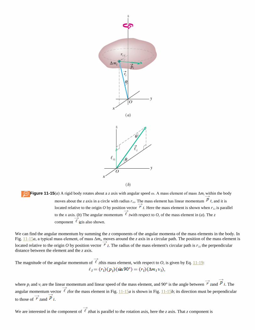
Figure 11-15 (a) A rigid body rotates about a z axis with angular speed ω. A mass element of mass Δmi within the body
moves about the z axis in a circle with radius r⊥i. The mass element has linear momentum , and it is
located relative to the origin O by position vector . Here the mass element is shown when r⊥i is parallel
to the x axis. (b) The angular momentum with respect to O, of the mass element in (a). The z
component is also shown.
We can find the angular momentum by summing the z components of the angular momenta of the mass elements in the body. In
Fig. 11-15a, a typical mass element, of mass Δmi, moves around the z axis in a circular path. The position of the mass element is
located relative to the origin O by position vector . The radius of the mass element's circular path is r⊥i the perpendicular
distance between the element and the z axis.
The magnitude of the angular momentum of this mass element, with respect to O, is given by Eq. 11-19:
where pi and vi are the linear momentum and linear speed of the mass element, and 90° is the angle between and . The
angular momentum vector for the mass element in Fig. 11-15a is shown in Fig. 11-15b; its direction must be perpendicular
to those of and .
We are interested in the component of that is parallel to the rotation axis, here the z axis. That z component is

The z component of the angular momentum for the rotating rigid body as a whole is found by adding up the contributions of all
the mass elements that make up the body. Thus, because v = ωr⊥, we may write
(11-30)
We can remove ω from the summation here because it has the same value for all points of the rotating rigid body.
The quantity in Eq. 11-30 is the rotational inertia I of the body about the fixed axis (see Eq. 10-33). Thus Eq. 11-30
reduces to
(11-31)
We have dropped the subscript z, but you must remember that the angular momentum defined by Eq. 11-31 is the angular
momentum about the rotation axis. Also, I in that equation is the rotational inertia about that same axis.
Table 11-1, which supplements Table 10-3, extends our list of corresponding linear and angular relations.
Table 11-1 More Corresponding Variables and Relations for Translational and Rotational Motion*
Translational Rotational
Force
Torque
Linear momentum
Angular momentum
Linear momentumb
Angular momentumb
Linear momentumb
Angular momentumc
Newton's second lawb
Newton's second lawb
Conservation lawd
Conservation lawd
CHECKPOINT 6
In the figure, a disk, a hoop, and a solid sphere are made to spin about fixed central axes (like a top)
by means of strings wrapped around them, with the strings producing the same constant tangential
force on all three objects. The three objects have the same mass and radius, and they are initially
stationary. Rank the objects according to (a) their angular momentum about their central axes and (b) their angular
speed, greatest first, when the strings have been pulled for a certain time t.
Top of Form

Copyright © 2011 John Wiley & Sons, Inc. All rights reserved.
11-11 Conservation of Angular Momentum
So far we have discussed two powerful conservation laws, the conservation of energy and the conservation of linear
momentum. Now we meet a third law of this type, involving the conservation of angular momentum. We start from Eq. 11-29
which is Newton's second law in angular form. If no net external torque acts on the system, this equation
becomes or
(11-32)
This result, called the law of conservation of angular momentum, can also be written as
(11-33)
Equations 11-32 and 11-33 tell us:
If the net external torque acting on a system is zero, the angular momentum of the system remains constant,
no matter what changes take place within the system.
Equations 11-34 and 11-41 are vector equations; as such, they are equivalent to three component equations corresponding to the
conservation of angular momentum in three mutually perpendicular directions. Depending on the torques acting on a system,
the angular momentum of the system might be conserved in only one or two directions but not in all directions:
If the component of the net external torque on a system along a certain axis is zero, then the component of the
angular momentum of the system along that axis cannot change, no matter what changes take place within the system.
We can apply this law to the isolated body in Fig. 11-15, which rotates around the z axis. Suppose that the initially rigid body
somehow redistributes its mass relative to that rotation axis, changing its rotational inertia about that axis. Equations 11-32 and

11-33 state that the angular momentum of the body cannot change. Substituting Eq. 11-31 (for the angular momentum along the
rotational axis) into Eq. 11-33, we write this conservation law as
(11-34)
Here the subscripts refer to the values of the rotational inertia I and angular speed ω before and after the redistribution of mass.
Like the other two conservation laws that we have discussed, Eqs. 11-32 and 11-33 hold beyond the limitations of Newtonian
mechanics. They hold for particles whose speeds approach that of light (where the theory of special relativity reigns), and they
remain true in the world of subatomic particles (where quantum physics reigns). No exceptions to the law of conservation of
angular momentum have ever been found.
We now discuss four examples involving this law.
1. The spinning volunteer. Figure 11-16 shows a student seated on a stool that can rotate freely about a vertical axis. The
student, who has been set into rotation at a modest initial angular speed ωi, holds two dumbbells in his outstretched hands.
His angular momentum vector lies along the vertical rotation axis, pointing upward.
Figure 11-16 (a) The student has a relatively large rotational inertia about the rotation axis and a relatively small
angular speed. (b) By decreasing his rotational inertia, the student automatically increases his angular

speed. The angular momentum of the rotating system remains unchanged.
The instructor now asks the student to pull in his arms; this action reduces his rotational inertia from its initial value Ii to a
smaller value If because he moves mass closer to the rotation axis. His rate of rotation increases markedly, from ωi to ωf.
The student can then slow down by extending his arms once more, moving the dumbbells outward.
No net external torque acts on the system consisting of the student, stool, and dumbbells. Thus, the angular momentum of
that system about the rotation axis must remain constant, no matter how the student maneuvers the dumbbells. In Fig. 11-
16a, the student's angular speed ωi is relatively low and his rotational inertia Ii is relatively high. According to Eq. 11-34, his
angular speed in Fig. 11-16b must be greater to compensate for the decreased If.
2. The springboard diver. Figure 11-17 shows a diver doing a forward one-anda-half-somersault dive. As you should expect,
her center of mass follows a parabolic path. She leaves the springboard with a definite angular momentum about an axis
through her center of mass, represented by a vector pointing into the plane of Fig. 11-17, perpendicular to the page. When
she is in the air, no net external torque acts on her about her center of mass, so her angular momentum about her center of
mass cannot change. By pulling her arms and legs into the closed tuck position, she can considerably reduce her rotational
inertia about the same axis and thus, according to Eq. 11-34, considerably increase her angular speed. Pulling out of the
tuck position (into the open layout position) at the end of the dive increases her rotational inertia and thus slows her
rotation rate so she can enter the water with little splash. Even in a more complicated dive involving both twisting and
somersaulting, the angular momentum of the diver must be conserved, in both magnitude and direction, throughout the
dive.
Figure 11-17 The diver's angular momentum is constant throughout the dive, being represented by the tail of
an arrow that is perpendicular to the plane of the figure. Note also that her center of mass (see the
dots) follows a parabolic path.
3. Long jump. When an athlete takes off from the ground in a running long jump, the forces on the launching foot give the
athlete an angular momentum with a forward rotation around a horizontal axis. Such rotation would not allow the jumper
to land properly: In the landing, the legs should be together and extended forward at an angle so that the heels mark the
sand at the greatest distance. Once airborne, the angular momentum cannot change (it is conserved) because no external
torque acts to change it. However, the jumper can shift most of the angular momentum to the arms by rotating them in
windmill fashion (Fig. 11-18). Then the body remains upright and in the proper orientation for landing.

Figure 11-18 Windmill motion of the arms during a long jump helps maintain body orientation for a proper
landing.
4. Tour jeté. In a tour jeté, a ballet performer leaps with a small twisting motion on the floor with one foot while holding the
other leg perpendicular to the body (Fig. 11-19a). The angular speed is so small that it may not be perceptible to the
audience. As the performer ascends, the outstretched leg is brought down and the other leg is brought up, with both ending
up at angle θ to the body (Fig. 11-19b). The motion is graceful, but it also serves to increase the rotation because bringing
in the initially outstretched leg decreases the performer's rotational inertia. Since no external torque acts on the airborne
performer, the angular momentum cannot change. Thus, with a decrease in rotational inertia, the angular speed must
increase. When the jump is well executed, the performer seems to suddenly begin to spin and rotates 180° before the initial
leg orientations are reversed in preparation for the landing. Once a leg is again outstretched, the rotation seems to vanish.

Figure 11-19 (a) Initial phase of a tour jeté: large rotational inertia and small angular speed. (b) Later phase:
smaller rotational inertia and larger angular speed.
CHECKPOINT 7
A rhinoceros beetle rides the rim of a small disk that rotates like a merry-go-round. If the
beetle crawls toward the center of the disk, do the following (each relative to the central axis)
increase, decrease, or remain the same for the beetle–disk system: (a) rotational inertia, (b)
angular momentum, and (c) angular speed?
Top of Form
Sample Problem
Conservation of angular momentum, rotating wheel demo
Figure 11-20a shows a student, again sitting on a stool that can rotate freely about a vertical axis. The student,
initially at rest, is holding a bicycle wheel whose rim is loaded with lead and whose rotational inertia Iwh about
its central axis is 1.2 kg·m2. (The rim contains lead in order to make the value of Iwh substantial.) The wheel is
rotating at an angular speed ωwh of 3.9 rev/s; as seen from overhead, the rotation is counterclockwise. The axis
of the wheel is vertical, and the angular momentum of the wheel points vertically upward. The student
now inverts the wheel (Fig. 11-20b) so that, as seen from overhead, it is rotating clockwise. Its angular
momentum is now The inversion results in the student, the stool, and the wheel's center rotating
together as a composite rigid body about the stool's rotation axis, with rotational inertia Ib = 6.8 kg·m2. (The
fact that the wheel is also rotating about its center does not affect the mass distribution of this composite body;
thus, Ib has the same value whether or not the wheel rotates.) With what angular speed ωb and in what
direction does the composite body rotate after the inversion of the wheel?

Figure 11-20 (a) A student holds a bicycle wheel rotating around a vertical axis. (b) The
student inverts the wheel, setting himself into rotation. (c) The net angular
momentum of the system must remain the same in spite of the inversion.
KEY IDEAS
1. The angular speed ωb we seek is related to the final angular momentum of the composite body about
the stool's rotation axis by Eq. 11-31 (L = Iω).
2. The initial angular speed ωwh of the wheel is related to the angular momentum of the wheel's
rotation about its center by the same equation.
3. The vector addition of and gives the total angular momentum of the system of the student,
stool, and wheel.
4. As the wheel is inverted, no net external torque acts on that system to change about any vertical
axis. (Torques due to forces between the student and the wheel as the student inverts the wheel are
internal to the system.) So, the system's total angular momentum is conserved about any vertical axis.
Calculations:
The conservation of is represented with vectors in Fig. 11-20c. We can also write this conservation in
terms of components along a vertical axis as
(11-35)
where i and f refer to the initial state (before inversion of the wheel) and the final state (after inversion).
Because inversion of the wheel inverted the angular momentum vector of the wheel's rotation, we substitute -

Lwh,i for Lwh,f. Then, if we set Lb,i = 0 (because the student, the stool, and the wheel's center were initially at
rest), Eq. 11-41 yields
Using Eq. 11-31, we next substitute Ibωb for Lb,f and Iwhωwh for Lwh,i and solve for ωb, finding
(Answer)
This positive result tells us that the student rotates counterclockwise about the stool axis as seen from
overhead. If the student wishes to stop rotating, he has only to invert the wheel once more.
Sample Problem
Conservation of angular momentum, cockroach on disk
In Fig. 11-21, a cockroach with mass m rides on a disk of mass 6.00m and radius R. The disk rotates like a
merry-go-round around its central axis at angular speed ωi = 1.50 rad/s. The cockroach is initially at radius r =
0.800R, but then it crawls out to the rim of the disk. Treat the cockroach as a particle. What then is the angular
speed?
Figure 11-21 A cockroach rides at radius r on a disk rotating
like a merry-go-round.
KEY IDEAS
(1) The cockroach's crawl changes the mass distribution (and thus the rotational inertia) of the cockroach–disk
system.
(2) The angular momentum of the system does not change because there is no external torque to change it.
(The forces and torques due to the cockroach's crawl are internal to the system.) (3) The magnitude of the
angular momentum of a rigid body or a particle is given by Eq. 11-31 (L = Iω).
Calculations:
We want to find the final angular speed. Our key is to equate the final angular momentum Lf to the initial
angular momentum Li, because both involve angular speed. They also involve rotational inertia I. So, let's start
by finding the rotational inertia of the system of cockroach and disk before and after the crawl.
The rotational inertia of a disk rotating about its central axis is given by Table 10-2c as Substituting

6.00m for the mass M, our disk here has rotational inertia
(11-36)
(We don't have values for m and R, but we shall continue with physics courage.)
From Eq. 10-33, we know that the rotational inertia of the cockroach (a particle) is equal to mr2. Substituting
the cockroach's initial radius (r = 0.800R) and final radius (r = R), we find that its initial rotational inertia about
the rotation axis is
(11-37)
and its final rotational inertia about the rotation axis is
(11-38)
So, the cockroach–disk system initially has the rotational inertia
(11-39)
and finally has the rotational inertia
(11-40)
Next, we use Eq. 11-31 (L = Iω) to write the fact that the system's final angular momentum Lf is equal to the
system's initial angular momentum Li:
or
After canceling the unknowns m and R, we come to
(Answer)
Note that the angular speed decreased because part of the mass moved outward from the rotation axis, thus
increasing the rotational inertia of the system.
Copyright © 2011 John Wiley & Sons, Inc. All rights reserved.
11-12 Precession of a Gyroscope
A simple gyroscope consists of a wheel fixed to a shaft and free to spin about the axis of the shaft. If one end of the shaft of a
nonspinning gyroscope is placed on a support as in Fig. 11-22a and the gyroscope is released, the gyroscope falls by rotating
downward about the tip of the support. Since the fall involves rotation, it is governed by Newton's second law in angular form, which is given by Eq. 11-29:
(11-41)

Figure 11-22 (a) A nonspinning gyroscope falls by rotating in an xz plane because of torque . (b) A rapidly spinning
gyroscope, with angular momentum , precesses around the z axis. Its precessional motion is in the xy
plane. (c) The change in angular momentum leads to a rotation of about O.
This equation tells us that the torque causing the downward rotation (the fall) changes the angular momentum of the
gyroscope from its initial value of zero. The torque is due to the gravitational force acting at the gyroscope's center of
mass, which we take to be at the center of the wheel. The moment arm relative to the support tip, located at O in Fig. 11-22a, is
. The magnitude of is
(11-42)
(because the angle between and is 90°), and its direction is as shown in Fig. 11-22a.

A rapidly spinning gyroscope behaves differently. Assume it is released with the shaft angled slightly upward. It first rotates
slightly downward but then, while it is still spinning about its shaft, it begins to rotate horizontally about a vertical axis through
support point O in a motion called precession.
Why does the spinning gyroscope stay aloft instead of falling over like the non-spinning gyroscope? The clue is that when the
spinning gyroscope is released, the torque due to must change not an initial angular momentum of zero but rather some
already existing nonzero angular momentum due to the spin.
To see how this nonzero initial angular momentum leads to precession, we first consider the angular momentum of the
gyroscope due to its spin. To simplify the situation, we assume the spin rate is so rapid that the angular momentum due to
precession is negligible relative to . We also assume the shaft is horizontal when precession begins, as in Fig. 11-22b. The
magnitude of is given by Eq. 11-31:
(11-43)
where I is the rotational moment of the gyroscope about its shaft and ω is the angular speed at which the wheel spins about the
shaft. The vector points along the shaft, as in Fig. 11-22b. Since is parallel to torque must be , torque must be
perpendicular to .
According to Eq. 11-41, torque causes an incremental change in the angular momentum of the gyroscope in an
incremental time interval dt; that is,
(11-44)
However, for a rapidly spinning gyroscope, the magnitude of is fixed by Eq. 11-43. Thus the torque can change only the
direction of , not its magnitude.
From Eq. 11-44 we see that the direction of is in the direction of perpendicular to . The only way that can be
changed in the direction of without the magnitude L being changed is for to rotate around the z axis as shown in Fig. 11-
22c. maintains its magnitude, the head of the vector follows a circular path, and is always tangent to that path. Since
must always point along the shaft, the shaft must rotate about the z axis in the direction of . Thus we have precession.
Because the spinning gyroscope must obey Newton's law in angular form in response to any change in its initial angular
momentum, it must precess instead of merely toppling over.
We can find the precession rate Ω by first using Eqs. 11-44 and 11-42 to get the magnitude of :
(11-45)
As changes by an incremental amount in an incremental time interval dt, the shaft and precess around the z axis through
incremental angle d. (In Fig. 11-22c, angle d is exaggerated for clarity.) With the aid of Eqs. 11-43 and 11-45, we find that d is
given by
Dividing this expression by dt and setting the rate Ω = d/dt, we obtain
(11-46)

This result is valid under the assumption that the spin rate ω is rapid. Note that Ω decreases as ω is increased. Note also that
there would be no precession if the gravitational force did not act on the gyroscope, but because I is a function of M, mass
cancels from Eq. 11-46; thus Ω is independent of the mass.
Equation 11-46 also applies if the shaft of a spinning gyroscope is at an angle to the horizontal. It holds as well for a spinning
top, which is essentially a spinning gyroscope at an angle to the horizontal.
Copyright © 2011 John Wiley & Sons, Inc. All rights reserved.
REVIEW & SUMMARY
Rolling Bodies For a wheel of radius R rolling smoothly,
(11-2)
where vcom is the linear speed of the wheel's center of mass and ω is the angular speed of the wheel about its center. The wheel
may also be viewed as rotating instantaneously about the point P of the “road” that is in contact with the wheel. The angular
speed of the wheel about this point is the same as the angular speed of the wheel about its center. The rolling wheel has kinetic
energy
(11-5)
where Icom is the rotational moment of the wheel about its center of mass and M is the mass of the wheel. If the wheel is being
accelerated but is still rolling smoothly, the acceleration of the center of mass is related to the angular acceleration α
about the center with
(11-6)
If the wheel rolls smoothly down a ramp of angle θ, its acceleration along an x axis extending up the ramp is
(11-10)
Torque as a Vector In three dimensions, torque is a vector quantity defined relative to a fixed point (usually an origin);
it is
(11-14)
where is a force applied to a particle and is a position vector locating the particle relative to the fixed point. The magnitude
of is given by
(11-15,11-16,11-17)
where is the angle between and , F⊥, is the component of perpendicular to and r⊥ is the moment arm of . The
direction of is given by the right-hand rule.

Angular Momentum of a Particle The angular momentum of a particle with linear momentum , mass m, and
linear velocity is a vector quantity defined relative to a fixed point (usually an origin) as
(11-18)
The magnitude of is given by
(11-19,11-20,11-21)
where is the angle between and , p⊥, and v⊥ are the components of and perpendicular to , and r⊥ is the perpendicular
distance between the fixed point and the extension of . The direction of is given by the right-hand rule for cross products.
Newton's Second Law in Angular Form Newton's second law for a particle can be written in angular form as
(11-23)
where is the net torque acting on the particle and is the angular momentum of the particle.
Angular Momentum of a System of Particles The angular momentum of a system of particles is the vector sum
of the angular momenta of the individual particles:
(11-26)
The time rate of change of this angular momentum is equal to the net external torque on the system (the vector sum of the
torques due to interactions of the particles of the system with particles external to the system):
(11-29)
Angular Momentum of a Rigid Body For a rigid body rotating about a fixed axis, the component of its angular
momentum parallel to the rotation axis is
(11-31)
Conservation of Angular Momentum The angular momentum of a system remains constant if the net external
torque acting on the system is zero:
(11-32)
or
(11-33)
This is the law of conservation of angular momentum.

Precession of a Gyroscope A spinning gyroscope can precess about a vertical axis through its support at the rate
(11-46)
where M is the gyroscope's mass, r is the moment arm, I is the rotational inertia, and ω is the spin rate.
Copyright © 2011 John Wiley & Sons, Inc. All rights reserved.
QUESTIONS
1 Figure 11-23 shows three particles of the same mass and the same constant speed moving as indicated by the
velocity vectors. Points a, b, c, and d form a square, with point e at the center. Rank the points according to
the magnitude of the net angular momentum of the three-particle system when measured about the points,
greatest first.
Figure 11-23 Question 1.
Top of Form
2 Figure 11-24 shows two particles A and B at xyz coordinates (1 m, 1 m, 0) and (1 m, 0, 1 m). Acting on each particle are
three numbered forces, all of the same magnitude and each directed parallel to an axis. (a) Which of the forces produce a
torque about the origin that is directed parallel to y? (b) Rank the forces according to the magnitudes of the torques they
produce on the particles about the origin, greatest first.
Figure 11-24 Question 2.
3 What happens to the initially stationary yo-yo in Fig. 11-25 if you pull it via its string with (a) force (the
line of action passes through the point of contact on the table, as indicated), (b) force (the line of action
passes above the point of contact), and (c) force (the line of action passes to the right of the point of contact)?
Top of Form

Figure 11-25 Question 3.
4 The position vector of a particle relative to a certain point has a magnitude of 3 m, and the force on the particle has a
magnitude of 4 N. What is the angle between the directions of and if the magnitude of the associated torque equals (a)
zero and (b) 12 N · m?
5 In Fig. 11-26, three forces of the same magnitude are applied to a particle at the origin ( acts directly into
the plane of the figure). Rank the forces according to the magnitudes of the torques they create about (a)
point P1, (b) point P2, and (c) point P3, greatest first.
Figure 11-26 Question 5.
Top of Form
6 The angular momenta ℓ(t) of a particle in four situations are (1) ℓ = 3t + 4; (2) ℓ = -6t2; (3) ℓ = 2; (4) ℓ = 4/t. In which
situation is the net torque on the particle (a) zero, (b) positive and constant, (c) negative and increasing in magnitude (t > 0),
and (d) negative and decreasing in magnitude (t > 0)?
7 A rhinoceros beetle rides the rim of a horizontal disk rotating counterclockwise like a merry-go-round. If the
beetle then walks along the rim in the direction of the rotation, will the magnitudes of the following
quantities (each measured about the rotation axis) increase, decrease, or remain the same (the disk is still
rotating in the counterclockwise direction): (a) the angular momentum of the beetle–disk system, (b) the
angular momentum and angular velocity of the beetle, and (c) the angular momentum and angular velocity of the disk? (d)
What are your answers if the beetle walks in the direction opposite the rotation?
Top of Form
8 Figure 11-27 shows an overhead view of a rectangular slab that can spin like a merry-go-round about its center at O. Also
shown are seven paths along which wads of bubble gum can be thrown (all with the same speed and mass) to stick onto the
stationary slab. (a) Rank the paths according to the angular speed that the slab (and gum) will have after the gum sticks,
greatest first. (b) For which paths will the angular momentum of the slab (and gum) about O be negative from the view of
Fig. 11-27?
Figure 11-27 Question 8.

9 Figure 11-28 gives the angular momentum magnitude L of a wheel versus time t. Rank the four lettered time
intervals according to the magnitude of the torque acting on the wheel, greatest first.
Figure 11-28 Question 9.
Top of Form
10 Figure 11-29 shows a particle moving at constant velocity and five points with their xy coordinates. Rank the points
according to the magnitude of the angular momentum of the particle measured about them, greatest first.
Figure 11-29 Question 10.
Copyright © 2011 John Wiley & Sons, Inc. All rights reserved.
PROBLEMS
sec. 11-2 Rolling as Translation and Rotation Combined
•1 A car travels at 80 km/h on a level road in the positive direction of an x axis. Each tire has a diameter of 66
cm. Relative to a woman riding in the car and in unit-vector notation, what are the velocity at the (a)
center, (b) top, and (c) bottom of the tire and the magnitude a of the acceleration at the (d) center, (e) top, and
(f) bottom of each tire? Relative to a hitchhiker sitting next to the road and in unit-vector notation, what are the velocity at
the (g) center, (h) top, and (i) bottom of the tire and the magnitude a of the acceleration at the (j) center, (k) top, and (l)
bottom of each tire?
Top of Form
•2 An automobile traveling at 80.0 km/h has tires of 75.0 cm diameter. (a) What is the angular speed of the tires about their
axles? (b) If the car is brought to a stop uniformly in 30.0 complete turns of the tires (without skidding), what is the
magnitude of the angular acceleration of the wheels? (c) How far does the car move during the braking?
sec. 11-4 The Forces of Rolling
•3 A 140 kg hoop rolls along a horizontal floor so that the hoop's center of mass has a speed of 0.150 m/s. How much work must be done on the hoop to stop it?
Top of Form
•4 A uniform solid sphere rolls down an incline. (a) What must be the incline angle if the linear acceleration of the center of the
sphere is to have a magnitude of 0.10g? (b) If a frictionless block were to slide down the incline at that angle, would its
acceleration magnitude be more than, less than, or equal to 0.10g? Why?

•5 A 1000 kg car has four 10 kg wheels. When the car is moving, what fraction of its total kinetic energy is
due to rotation of the wheels about their axles? Assume that the wheels have the same rotational inertia as
uniform disks of the same mass and size. Why do you not need to know the radius of the wheels?
Top of Form
••6 Figure 11-30 gives the speed v versus time t for a 0.500 kg object of radius 6.00 cm that rolls smoothly down a 30° ramp.
The scale on the velocity axis is set by vs = 4.0 m/s. What is the rotational inertia of the object?
Figure 11-30 Problem 6.
••7 In Fig. 11-31, a solid cylinder of radius 10 cm and mass 12 kg starts from rest and rolls without slipping
a distance L = 6.0 m down a roof that is inclined at the angle θ = 30°. (a) What is the angular speed of the
cylinder about its center as it leaves the roof? (b) The roof's edge is at height H = 5.0 m. How far horizontally
from the roof's edge does the cylinder hit the level ground?
Figure 11-31 Problem 7.
Top of Form
••8 Figure 11-32 shows the potential energy U(x) of a solid ball that can roll along an x axis. The scale on the U axis is set by Us
= 100 J. The ball is uniform, rolls smoothly, and has a mass of 0.400 kg. It is released at x = 7.0 m headed in the negative
direction of the x axis with a mechanical energy of 75 J. (a) If the ball can reach x = 0 m, what is its speed there, and if it
cannot, what is its turning point? Suppose, instead, it is headed in the positive direction of the x axis when it is released at x
= 7.0 m with 75 J. (b) If the ball can reach x = 13 m, what is its speed there, and if it cannot, what is its turning point?

Figure 11-32 Problem 8.
••9 In Fig. 11-33, a solid ball rolls smoothly from rest (starting at height H = 6.0 m) until it leaves the
horizontal section at the end of the track, at height h = 2.0 m. How far horizontally from point A does the ball
hit the floor?
Figure 11-33 Problem 9.
Top of Form
••10 A hollow sphere of radius 0.15 m, with rotational inertia I = 0.040 kg·m2 about a line through its center of mass, rolls
without slipping up a surface inclined at 30° to the horizontal. At a certain initial position, the sphere's total kinetic energy
is 20 J. (a) How much of this initial kinetic energy is rotational? (b) What is the speed of the center of mass of the sphere at
the initial position? When the sphere has moved 1.0 m up the incline from its initial position, what are (c) its total kinetic
energy and (d) the speed of its center of mass?
••11 In Fig. 11-34, a constant horizontal force of magnitude 10 N is applied to a wheel of mass 10 kg and
radius 0.30 m. The wheel rolls smoothly on the horizontal surface, and the acceleration of its center of mass
has magnitude 0.60 m/s2. (a) In unit-vector notation, what is the frictional force on the wheel? (b) What is
the rotational inertia of the wheel about the rotation axis through its center of mass?
Figure 11-34 Problem 11.
Top of Form
••12 In Fig. 11-35, a solid brass ball of mass 0.280 g will roll smoothly along a loop-the-loop track when released from rest
along the straight section. The circular loop has radius R = 14.0 cm, and the ball has radius r R. (a) What is h if the ball
is on the verge of leaving the track when it reaches the top of the loop? If the ball is released at height h = 6.00R, what are
the (b) magnitude and (c) direction of the horizontal force component acting on the ball at point Q?
Figure 11-35 Problem 12.
•••13 Top of Form

Nonuniform ball. In Fig. 11-36, a ball of mass M and radius R rolls smoothly from rest down a ramp and
onto a circular loop of radius 0.48 m. The initial height of the ball is h = 0.36 m. At the loop bottom, the magnitude of the
normal force on the ball is 2.00Mg. The ball consists of an outer spherical shell (of a certain uniform density) that is glued
to a central sphere (of a different uniform density). The rotational inertia of the ball can be expressed in the general form I
= βMR2, but β is not 0.4 as it is for a ball of uniform density. Determine β.
Figure 11-36 Problem 13.
•••14 In Fig. 11-37, a small, solid, uniform ball is to be shot from point P so that it rolls smoothly along a horizontal path, up
along a ramp, and onto a plateau. Then it leaves the plateau horizontally to land on a game board, at a horizontal distance d
from the right edge of the plateau. The vertical heights are h1 = 5.00 cm and h2 = 1.60 cm. With what speed must the ball
be shot at point P for it to land at d = 6.00 cm?
Figure 11-37 Problem 14.
•••15 A bowler throws a bowling ball of radius R = 11 cm along a lane. The ball (Fig. 11-38) slides on the
lane with initial speed vcom,0 = 8.5 m/s and initial angular speed ω0 = 0. The coefficient of kinetic friction
between the ball and the lane is 0.21. The kinetic frictional force acting on the ball causes a linear
acceleration of the ball while producing a torque that causes an angular acceleration of the ball. When speed vcom has
decreased enough and angular speed ω has increased enough, the ball stops sliding and then rolls smoothly. (a) What then
is vcom in terms of ω? During the sliding, what are the ball's (b) linear acceleration and (c) angular acceleration? (d) How
long does the ball slide? (e) How far does the ball slide? (f) What is the linear speed of the ball when smooth rolling
begins?
Figure 11-38 Problem 15.
Top of Form
•••16 Nonuniform cylindrical object. In Fig. 11-39, a cylindrical object of mass M and radius R rolls smoothly from rest down a
ramp and onto a horizontal section. From there it rolls off the ramp and onto the floor, landing a horizontal distance d =
0.506 m from the end of the ramp. The initial height of the object is H = 0.90 m; the end of the ramp is at height h = 0.10
m. The object consists of an outer cylindrical shell (of a certain uniform density) that is glued to a central cylinder (of a
different uniform density). The rotational inertia of the object can be expressed in the general form I = βMR2, but β is not
0.5 as it is for a cylinder of uniform density. Determine β.

Figure 11-39 Problem 16.
sec. 11-5 The Yo-Yo
•17 A yo-yo has a rotational inertia of 950 g·cm2 and a mass of 120 g. Its axle radius is 3.2 mm,
and its string is 120 cm long. The yo-yo rolls from rest down to the end of the string. (a) What is the
magnitude of its linear acceleration? (b) How long does it take to reach the end of the string? As it reaches
the end of the string, what are its (c) linear speed, (d) translational kinetic energy, (e) rotational kinetic energy, and (f)
angular speed?
Top of Form
•18 In 1980, over San Francisco Bay, a large yo-yo was released from a crane. The 116 kg yo-yo consisted of two
uniform disks of radius 32 cm connected by an axle of radius 3.2 cm. What was the magnitude of the acceleration of the yo-
yo during (a) its fall and (b) its rise? (c) What was the tension in the cord on which it rolled? (d) Was that tension near the
cord's limit of 52 kN? Suppose you build a scaled-up version of the yo-yo (same shape and materials but larger). (e) Will the
magnitude of your yo-yo's acceleration as it falls be greater than, less than, or the same as that of the San Francisco yo-yo?
(f) How about the tension in the cord?
sec. 11-6 Torque Revisited
•19 In unit-vector notation, what is the net torque about the origin on a flea located at coordinates (0, -4.0 m, 5.0
m) when forces act on the flea?
Top of Form
•20 A plum is located at coordinates (-2.0 m, 0, 4.0 m). In unit-vector notation, what is the torque about the origin on the plum if
that torque is due to a force whose only component is (a) Fx = 6.0 N, (b)Fx = -6.0 N, (c) Fz = 6.0 N, and (d) Fz = -6.0 N?
•21 In unit-vector notation, what is the torque about the origin on a particle located at coordinates (0, -4.0 m, 3.0
m) if that torque is due to (a) force with components F1x = 2.0 N, F1y = F1z = 0, and (b) force
components F2x = 0, F2y = 2.0 N, F2z = 4.0 N?
Top of Form
••22 A particle moves through an xyz coordinate system while a force acts on the particle. When the particle has the position
vector the force is given by and the
corresponding torque about the origin is . Determine Fx.
••23
Force acts on a pebble with position vector
relative to the origin. In unit-vector notation, what is the resulting torque on the pebble about (a) the origin
and (b) the point (2.0 m, 0, -3.0 m)?
Top of Form
••24 In unit-vector notation, what is the torque about the origin on a jar of jalapeño peppers located at coordinates (3.0 m, -2.0
m, 4.0 m) due to (a) force (b) force
and (c) the vector sum of and ? (d) Repeat part (c) for the torque
about the point with coordinates (3.0 m, 2.0 m, 4.0 m).
••25
Force acts on a particle with position vector
. What are (a) the torque on the particle about the origin, in unit-vector notation,
Top of Form

and (b) the angle between the directions of and ?
sec. 11-7 Angular Momentum
•26 At the instant of Fig. 11-40, a 2.0 kg particle P has a position vector of magnitude 3.0 m and angle θ1 = 45° and a velocity
vector of magnitude 4.0 m/s and angle θ2 = 30°. Force , of magnitude 2.0 N and angle θ3 = 30°, acts on P. All three
vectors lie in the xy plane. About the origin, what are the (a) magnitude and (b) direction of the angular momentum of P and
the (c) magnitude and (d) direction of the torque acting on P?
Figure 11-40 Problem 26.
•27 At one instant, force acts on a 0.25 kg object that has position vector
and velocity vector . About the origin and in unit-
vector notation, what are (a) the object's angular momentum and (b) the torque acting on the object?
Top of Form
•28 A 2.0 kg particle-like object moves in a plane with velocity components vx = 30 m/s and vy = 60 m/s as it passes through the
point with (x, y) coordinates of (3.0, -4.0) m. Just then, in unit-vector notation, what is its angular momentum relative to (a)
the origin and (b) the point located at (-2.0, -2.0) m?
•29 In the instant of Fig. 11-41, two particles move in an xy plane. Particle P1 has mass 6.5 kg and speed v1
= 2.2 m/s, and it is at distance d1 = 1.5 m from point O. Particle P2 has mass 3.1 kg and speed v2 = 3.6 m/s,
and it is at distance d2 = 2.8 m from point O. What are the (a) magnitude and (b) direction of the net angular
momentum of the two particles about O?
Figure 11-41 Problem 29.
Top of Form
••30
At the instant the displacement of a 2.00 kg object relative to the origin is its
velocity is and it is subject to a force
Find (a) the acceleration of the object, (b) the angular momentum of the
object about the origin, (c) the torque about the origin acting on the object, and (d) the angle between the velocity of the
object and the force acting on the object.
••31 In Fig. 11-42, a 0.400 kg ball is shot directly upward at initial speed 40.0 m/s. What is its angular
momentum about P, 2.00 m horizontally from the launch point, when the ball is (a) at maximum height and
(b) halfway back to the ground? What is the torque on the ball about P due to the gravitational force when
the ball is (c) at maximum height and (d) halfway back to the ground?
Top of Form

Figure 11-42 Problem 31.
sec. 11-8 Newton's Second Law in Angular Form
•32 A particle is acted on by two torques about the origin: has a magnitude of 2.0 N·m and is directed in the positive
direction of the x axis, and has a magnitude of 4.0 N·m and is directed in the negative direction of the y axis. In unit-
vector notation, find where is the angular momentum of the particle about the origin.
•33 At time t = 0, a 3.0 kg particle with velocity is at x = 3.0
m, y = 8.0 m. It is pulled by a 7.0 N force in the negative x direction. About the origin, what are (a) the
particle's angular momentum, (b) the torque acting on the particle, and (c) the rate at which the angular
momentum is changing?
Top of Form
•34 A particle is to move in an xy plane, clockwise around the origin as seen from the positive side of the z axis. In unit-vector
notation, what torque acts on the particle if the magnitude of its angular momentum about the origin is (a) 4.0 kg·m2/s, (b)
4.0t2 kg·m
2/s, (c) 4.0 kg · m
2/s, and (d) 4.0/t
2 kg·m
2/s?
••35
At time t, the vector gives the position of a 3.0 kg particle relative to the
origin of an xy coordinate system ( is in meters and t is in seconds). (a) Find an expression for the torque
acting on the particle relative to the origin. (b) Is the magnitude of the particle's angular momentum relative to the origin
increasing, decreasing, or unchanging?
Top of Form
sec. 11-10 The Angular Momentum of a Rigid Body Rotating About a Fixed Axis
•36 Figure 11-43 shows three rotating, uniform disks that are coupled by belts. One belt runs around the rims of disks A and C.
Another belt runs around a central hub on disk A and the rim of disk B. The belts move smoothly without slippage on the
rims and hub. Disk A has radius R; its hub has radius 0.5000R; disk B has radius 0.2500R; and disk C has radius 2.000R.
Disks B and C same density (mass per unit volume) and thickness. What is the ratio of the magnitude of the angular
momentum of disk C to that of disk B?
Figure 11-43 Problem 36.
•37 In Fig. 11-44, three particles of mass m = 23 g are fastened to three rods of length d = 12 cm and
negligible mass. The rigid assembly rotates around point O at the angular speed ω = 0.85 rad/s. About O,
what are (a) the rotational inertia of the assembly, (b) the magnitude of the angular momentum of the middle
particle, and (c) the magnitude of the angular momentum of the asssembly?
Figure 11-44 Problem 37.
Top of Form

•38 A sanding disk with rotational inertia 1.2 × 10⁻³
kg·m2 is attached to an electric drill whose motor delivers a torque of
magnitude 16 N · m about the central axis of the disk. About that axis and with the torque applied for 33 ms, what is the
magnitude of the (a) angular momentum and (b) angular velocity of the disk?
•39 The angular momentum of a flywheel having a rotational inertia of 0.140 kg·m2 about its central axis
decreases from 3.00 to 0.800 kg·m2/s in 1.50 s. (a) What is the magnitude of the average torque acting on the
flywheel about its central axis during this period? (b) Assuming a constant angular acceleration, through
what angle does the flywheel turn? (c) How much work is done on the wheel? (d) What is the average power of the
flywheel?
Top of Form
••40 A disk with a rotational inertia of 7.00 kg·m2 rotates like a merry-go-round while undergoing a variable torque given by τ =
(5.00 + 2.00t) N·m. At time t = 1.00s, its angular momentum is 5.00 kg·m2/s. What is its angular momentum at t = 3.00s?
••41 Figure 11-45 shows a rigid structure consisting of a circular hoop of radius R and mass m, and a square
made of four thin bars, each of length R and mass m. The rigid structure rotates at a constant speed about a
vertical axis, with a period of rotation of 2.5 s. Assuming R = 0.50 m and m = 2.0 kg, calculate (a) the
structure's rotational inertia about the axis of rotation and (b) its angular momentum about that axis.
Figure 11-45 Problem 41.
Top of Form
••42 Figure 11-46 gives the torque τ that acts on an initially stationary disk that can rotate about its center like a merry-go-round.
Figure 11-46 Problem 42.
The scale on the τs = 4.0 N·m. What is the angular momentum of the disk about the rotation axis at times (a) t = 7.0 s and
(b) t = 20 s?
sec. 11-11 Conservation of Angular Momentum
•43 In Fig. 11-47, two skaters, each of mass 50 kg, approach each other along parallel paths separated by 3.0 m.
They have opposite velocities of 1.4 m/s each. One skater carries one end of a long pole of negligible mass,
and the other skater grabs the other end as she passes. The skaters then rotate around the center of the pole.
Assume that the friction between skates and ice is negligible. What are (a) the radius of the circle, (b) the
Top of Form

angular speed of the skaters, and (c) the kinetic energy of the two-skater system? Next, the skaters pull along the pole until
they are separated by 1.0 m. What then are (d) their angular speed and (e) the kinetic energy of the system? (f) What
provided the energy for the increased kinetic energy?
Figure 11-47 Problem 43.
•44 A Texas cockroach of mass 0.17 kg runs counterclockwise around the rim of a lazy Susan (a circular disk mounted on a
vertical axle) that has radius 15 cm, rotational inertia 5.0 × 10⁻³
kg·m2, and frictionless bearings. The cockroach's speed
(relative to the ground) is 2.0 m/s, and the lazy Susan turns clockwise with angular speed ω0 = 2.8 rad/s. The cockroach
finds a bread crumb on the rim and, of course, stops. (a) What is the angular speed of the lazy Susan after the cockroach
stops? (b) Is mechanical energy conserved as it stops?
•45 A man stands on a platform that is rotating (without friction) with an angular speed of 1.2
rev/s; his arms are outstretched and he holds a brick in each hand. The rotational inertia of the system
consisting of the man, bricks, and platform about the central vertical axis of the platform is 6.0 kg·m2. If by
moving the bricks the man decreases the rotational inertia of the system to 2.0 kg·m2, what are (a) the resulting angular
speed of the platform and (b) the ratio of the new kinetic energy of the system to the original kinetic energy? (c) What
source provided the added kinetic energy?
Top of Form
•46 The rotational inertia of a collapsing spinning star drops to its initial value. What is the ratio of the new rotational kinetic
energy to the initial rotational kinetic energy?
•47 A track is mounted on a large wheel that is free to turn with negligible friction about a vertical axis
(Fig. 11-48). A toy train of mass m is placed on the track and, with the system initially at rest, the train's
electrical power is turned on. The train reaches speed 0.15 m/s with respect to the track. What is the angular
speed of the wheel if its mass is 1.1m and its radius is 0.43 m? (Treat the wheel as a hoop, and neglect the mass of the
spokes and hub.)
Figure 11-48 Problem 47.
Top of Form
•48 A Texas cockroach first rides at the center of a circular disk that rotates freely like a merry-go-round without external
torques. The cockroach then walks out to the edge of the disk, at radius R. Figure 11-49 gives the angular speed ω of the
cockroach–disk system during the walk. The scale on the ω axis is set by ωa = 5.0 rad/s and ωb = 6.0 rad/s. When the
cockroach is on the edge at radius R, what is the ratio of the bug's rotational inertia to that of the disk, both calculated about
the rotation axis?
Figure 11-49 Problem 48.

•49 Two disks are mounted (like a merry-go-round) on low-friction bearings on the same axle and can be brought
together so that they couple and rotate as one unit. The first disk, with rotational inertia 3.30 kg·m2 about its
central axis, is set spinning counterclockwise at 450 rev/min. The second disk, with rotational inertia 6.60
kg·m2 about its central axis, is set spinning counterclockwise at 900 rev/min. They then couple together. (a)
What is their angular speed after coupling? If instead the second disk is set spinning clockwise at 900 rev/min, what are their
(b) angular speed and (c) direction of rotation after they couple together?
Top of Form
•50 The rotor of an electric motor has rotational inertia Im = 2.0 × 10⁻³
kg·m2 about its central axis. The motor is used to change
the orientation of the space probe in which it is mounted. The motor axis is mounted along the central axis of the probe; the
probe has rotational inertia Ip = 12 kg·m2 about this axis. Calculate the number of revolutions of the rotor required to turn
the probe through 30° about its central axis.
•51 A wheel is rotating freely at angular speed 800 rev/min on a shaft whose rotational inertia is
negligible. A second wheel, initially at rest and with twice the rotational inertia of the first, is suddenly
coupled to the same shaft. (a) What is the angular speed of the resultant combination of the shaft and two
wheels? (b) What fraction of the original rotational kinetic energy is lost?
Top of Form
••52 A cockroach of mass m lies on the rim of a uniform disk of mass 4.00m that can rotate freely about its center like a
merry-go-round. Initially the cockroach and disk rotate together with an angular velocity of 0.260 rad/s. Then the cockroach
walks halfway to the center of the disk. (a) What then is the angular velocity of the cockroach–disk system? (b) What is the
ratio K/K0 of the new kinetic energy of the system to its initial kinetic energy? (c) What accounts for the change in the
kinetic energy?
••53 A uniform thin rod of length 0.500 m and mass 4.00 kg can rotate in a horizontal plane about a vertical
axis through its center. The rod is at rest when a 3.00 g bullet traveling in the rotation plane is fired into one
end of the rod. As viewed from above, the bullet's path makes angle θ = 60.0° with the rod (Fig. 11-50). If
the bullet lodges in the rod and the angular velocity of the rod is 10 rad/s immediately after the collision, what is the bullet's
speed just before impact?
Figure 11-50 Problem 53.
Top of Form
••54 Figure 11-51 shows an overhead view of a ring that can rotate about its center like a merry-go-round. Its outer radius R2
is 0.800 m, its inner radius R1 is R2/2.00, its mass M is 8.00 kg, and the mass of the crossbars at its center is negligible. It
initially rotates at an angular speed of 8.00 rad/s with a cat of mass m = M /4.00 on its outer edge, at radius R2. By how
much does the cat increase the kinetic energy of the cat–ring system if the cat crawls to the inner edge, at radius R1?
Figure 11-51 Problem 54.
••55 Top of Form

A horizontal vinyl record of mass 0.10 kg and radius 0.10 m rotates freely about a vertical axis through its
center with an angular speed of 4.7 rad/s. The rotational inertia of the record about its axis of rotation is 5.0 × 10⁻⁴
kg·m2. A
wad of wet putty of mass 0.020 kg drops vertically onto the record from above and sticks to the edge of the record. What is
the angular speed of the record immediately after the putty sticks to it?
••56 In a long jump, an athlete leaves the ground with an initial angular momentum that tends to rotate her body forward,
threatening to ruin her landing. To counter this tendency, she rotates her outstretched arms to “take up” the angular
momentum (Fig. 11-18). In 0.700 s, one arm sweeps through 0.500 rev and the other arm sweeps through 1.000 rev. Treat
each arm as a thin rod of mass 4.0 kg and length 0.60 m, rotating around one end. In the athlete's reference frame, what is
the magnitude of the total angular momentum of the arms around the common rotation axis through the shoulders?
••57 A uniform disk of mass 10m and radius 3.0r can rotate freely about its fixed center like a merry-go-round. A
smaller uniform disk of mass m and radius r lies on top of the larger disk, concentric with it. Initially the two
disks rotate together with an angular velocity of 20 rad/s. Then a slight disturbance causes the smaller disk
to slide outward across the larger disk, until the outer edge of the smaller disk catches on the outer edge of
the larger disk. Afterward, the two disks again rotate together (without further sliding). (a) What then is their angular
velocity about the center of the larger disk? (b) What is the ratio K/K0 of the new kinetic energy of the two-disk system to
the system's initial kinetic energy?
Top of Form
••58 A horizontal platform in the shape of a circular disk rotates on a frictionless bearing about a vertical axle through the center
of the disk. The platform has a mass of 150 kg, a radius of 2.0 m, and a rotational inertia of 300 kg·m2 about the axis of
rotation. A 60 kg student walks slowly from the rim of the platform toward the center. If the angular speed of the system is
1.5 rad/s when the student starts at the rim, what is the angular speed when she is 0.50 m from the center?
••59 Figure 11-52 is an overhead view of a thin uniform rod of length 0.800 m and mass M rotating horizontally
at angular speed 20.0 rad/s about an axis through its center. A particle of mass M/3.00 initially attached to
one end is ejected from the rod and travels along a path that is perpendicular to the rod at the instant of
ejection. If the particle's speed vp is 6.00 m/s greater than the speed of the rod end just after ejection, what is
the value of vp?
Figure 11-52 Problem 59.
Top of Form
••60 In Fig. 11-53, a 1.0 g bullet is fired into a 0.50 kg block attached to the end of a 0.60 m nonuniform rod of mass 0.50 kg.
The block–rod–bullet system then rotates in the plane of the figure, about a fixed axis at A. The rotational inertia of the rod
alone about that axis at A is 0.060 kg·m2. Treat the block as a particle. (a) What then is the rotational inertia of the block–
rod–bullet system about point A? (b) If the angular speed of the system about A just after impact is 4.5 rad/s, what is the
bullet's speed just before impact?
Figure 11-53 Problem 60.
••61 The uniform rod (length 0.60 m, mass 1.0 kg) in Fig. 11-54 rotates in the plane of the figure about an axis
through one end, with a rotational inertia of 0.12 kg·m2. As the rod swings through its lowest position, it
collides with a 0.20 kg putty wad that sticks to the end of the rod. If the rod's angular speed just before
collision is 2.4 rad/s, what is the angular speed of the rod–putty system immediately after collision?
Top of Form

Figure 11-54 Problem 61.
•••62 During a jump to his partner, an aerialist is to make a quadruple somersault lasting a time t = 1.87 s. For the first
and last quarter-revolution, he is in the extended orientation shown in Fig. 11-55, with rotational inertia I1 = 19.9 kg·m2
around his center of mass (the dot). During the rest of the flight he is in a tight tuck, with rotational inertia I2 = 3.93 kg·m2.
What must be his angular speed ω2 around his center of mass during the tuck?
Figure 11-55 Problem 62.
•••63 In Fig. 11-56, a 30 kg child stands on the edge of a stationary merry-go-round of radius 2.0 m. The
rotational inertia of the merry-go-round about its rotation axis is 150 kg·m2. The child catches a ball of
mass 1.0 kg thrown by a friend. Just before the ball is caught, it has a horizontal velocity of magnitude 12
m/s, at angle = 37° with a line tangent to the outer edge of the merry-go-round, as shown. What is the angular speed of the
merry-go-round just after the ball is caught?
Top of Form

Figure 11-56 Problem 63.
•••64 A ballerina begins a tour jeté (Fig. 11-19a) with angular speed ωi and a rotational inertia consisting of two parts:
Ileg = 1.44 kg·m2 for her leg extended outward at angle θ = 90.0° to her body and Itrunk = 0.660 kg·m
2 for the rest of her
body (primarily her trunk). Near her maximum height she holds both legs at angle θ = 30.0° to her body and has angular
speed ωf (Fig. 11-19b). Assuming that Itrunk has not changed, what is the ratio ωf /ωi?
•••65 Two 2.00 kg balls are attached to the ends of a thin rod of length 50.0 cm and negligible
mass. The rod is free to rotate in a vertical plane without friction about a horizontal axis through its center.
With the rod initially horizontal (Fig. 11-57), a 50.0 g wad of wet putty drops onto one of the balls, hitting
it with a speed of 3.00 m/s and then sticking to it. (a) What is the angular speed of the system just after the putty wad hits?
(b) What is the ratio of the kinetic energy of the system after the collision to that of the putty wad just before? (c) Through
what angle will the system rotate before it momentarily stops?
Figure 11-57 Problem 65.
Top of Form
•••66 In Fig. 11-58, a small 50 g block slides down a frictionless surface through height h = 20 cm and then sticks to a uniform
rod of mass 100 g and length 40 cm. The rod pivots about point O through angle θ before momentarily stopping. Find θ.
Figure 11-58 Problem 66.
•••67 Figure 11-59 is an overhead view of a thin uniform rod of length 0.600 m and mass M rotating horizontally
at 80.0 rad/s counterclockwise about an axis through its center. A particle of mass M/3.00 and traveling
horizontally at speed 40.0 m/s hits the rod and sticks. The particle's path is perpendicular to the rod at the
instant of the hit, at a distance d from the rod's center. (a) At what value of d are rod and particle stationary
after the hit? (b) In which direction do rod and particle rotate if d is greater than this value?
Figure 11-59 Problem 67.
Top of Form
sec. 11-12 Precession of a Gyroscope
••68 A top spins at 30 rev/s about an axis that makes an angle of 30° with the vertical. The mass of the top is 0.50 kg, its

rotational inertia about its central axis is 5.0 × 10⁻⁴
kg·m2, and its center of mass is 4.0 cm from the pivot point. If the spin is
clockwise from an overhead view, what are the (a) precession rate and (b) direction of the precession as viewed from
overhead?
••69 A certain gyroscope consists of a uniform disk with a 50 cm radius mounted at the center of an axle that is
11 cm long and of negligible mass. The axle is horizontal and supported at one end. If the disk is spinning
around the axle at 1000 rev/min, what is the precession rate?
Top of Form
Additional Problems
70 A uniform solid ball rolls smoothly along a floor, then up a ramp inclined at 15.0°. It momentarily stops when it has rolled
1.50 m along the ramp. What was its initial speed?
71 In Fig. 11-60, a constant horizontal force of magnitude 12 N is applied to a uniform solid
cylinder by fishing line wrapped around the cylinder. The mass of the cylinder is 10 kg, its radius is 0.10 m,
and the cylinder rolls smoothly on the horizontal surface. (a) What is the magnitude of the acceleration of the
center of mass of the cylinder? (b) What is the magnitude of the angular acceleration of the cylinder about the center of
mass? (c) In unit-vector notation, what is the frictional force acting on the cylinder?
Figure 11-60 Problem 71.
Top of Form
72 A thin-walled pipe rolls along the floor. What is the ratio of its translational kinetic energy to its rotational kinetic energy
about the central axis parallel to its length?
73 A 3.0 kg toy car moves along an x axis with a velocity given by with t in
seconds. For t > 0, what are (a) the angular momentum of the car and (b) the torque on the car, both
calculated about the origin? What are (c) and (d) about the point (2.0 m, 5.0 m, 0)? What are (e) and (f) about the
point (2.0 m, -5.0 m, 0)?
Top of Form
74 A wheel rotates clockwise about its central axis with an angular momentum of 600 kg·m2/s. At time t = 0, a torque of
magnitude 50 N m is applied to the wheel to reverse the rotation. At what time t is the angular speed zero?
75 In a playground, there is a small merry-go-round of radius 1.20 m and mass 180 kg. Its radius of
gyration (see Problem 79 of Chapter 10) is 91.0 cm. A child of mass 44.0 kg runs at a speed of 3.00 m/s
along a path that is tangent to the rim of the initially stationary merry-go-round and then jumps on. Neglect
friction between the bearings and the shaft of the merry-go-round. Calculate (a) the rotational inertia of the merry-go-round
about its axis of rotation, (b) the magnitude of the angular momentum of the running child about the axis of rotation of the
merry-go-round, and (c) the angular speed of the merry-go-round and child after the child has jumped onto the merry-go-
round.
Top of Form
76 A uniform block of granite in the shape of a book has face dimensions of 20 cm and 15 cm and a thickness of 1.2 cm. The
density (mass per unit volume) of granite is 2.64 g/cm3. The block rotates around an axis that is perpendicular to its face and
halfway between its center and a corner. Its angular momentum about that axis is 0.104 kg·m2/s. What is its rotational
kinetic energy about that axis?
77 Two particles, each of mass 2.90 × 10⁻⁴
kg and speed 5.46 m/s, travel in opposite directions along
parallel lines separated by 4.20 cm. (a) What is the magnitude L of the angular momentum of the two-particle
system around a point midway between the two lines? (b) Does the value of L change if the point about
which it is calculated is not midway between the lines? If the direction of travel for one of the particles is reversed, what
would be (c) the answer to part (a) and (d) the answer to part (b)?
Top of Form
78 A wheel of radius 0.250 m, which is moving initially at 43.0 m/s, rolls to a stop in 225 m. Calculate the magnitudes of (a) its
linear acceleration and (b) its angular acceleration. (c) The wheel's rotational inertia is 0.155 kg·m2 about its central axis.
Calculate the magnitude of the torque about the central axis due to friction on the wheel.

79 Wheels A and B in Fig. 11-61 are connected by a belt that does not slip. The radius of B is 3.00 times the
radius of A. What would be the ratio of the rotational inertias IA/IB if the two wheels had (a) the same angular
momentum about their central axes and (b) the same rotational kinetic energy?
Figure 11-61 Problem 79.
Top of Form
80 A 2.50 kg particle that is moving horizontally over a floor with velocity undergoes a completely inelastic
collision with a 4.00 kg particle that is moving horizontally over the floor with velocity The collision occurs
at xy coordinates (-0.500 m, -0.100 m). After the collision and in unit-vector notation, what is the angular momentum of the
stuck-together particles with respect to the origin?
81 A uniform wheel of mass 10.0 kg and radius 0.400 m is mounted rigidly on a massless axle through its
center (Fig. 11-62). The radius of the axle is 0.200 m, and the rotational inertia of the wheel–axle
combination about its central axis is 0.600 kg·m2. The wheel is initially at rest at the top of a surface that is
inclined at angle θ = 30.0° with the horizontal; the axle rests on the surface while the wheel extends into a groove in the
surface without touching the surface. Once released, the axle rolls down along the surface smoothly and without slipping.
When the wheel–axle combination has moved down the surface by 2.00 m, what are (a) its rotational kinetic energy and (b)
its translational kinetic energy?
Figure 11-62 Problem 81.
Top of Form
82 A uniform rod rotates in a horizontal plane about a vertical axis through one end. The rod is 6.00 m long, weighs 10.0 N,
and rotates at 240 rev/min. Calculate (a) its rotational inertia about the axis of rotation and (b) the magnitude of its angular
momentum about that axis.
83 A solid sphere of weight 36.0 N rolls up an incline at an angle of 30.0°. At the bottom of the incline the
center of mass of the sphere has a translational speed of 4.90 m/s. (a) What is the kinetic energy of the sphere
at the bottom of the incline? (b) How far does the sphere travel up along the incline? (c) Does the answer to
(b) depend on the sphere's mass?
Top of Form
84 Suppose that the yo-yo in Problem 17, instead of rolling from rest, is thrown so that its initial speed down the string
is 1.3 m/s. (a) How long does the yo-yo take to reach the end of the string? As it reaches the end of the string, what are its
(b) total kinetic energy, (c) linear speed, (d) translational kinetic energy, (e) angular speed, and (f) rotational kinetic energy?
85 A girl of mass M stands on the rim of a frictionless merry-go-round of radius R and rotational inertia I that is
not moving. She throws a rock of mass m horizontally in a direction that is tangent to the outer edge of the
merry-go-round. The speed of the rock, relative to the ground, is v. Afterward, what are (a) the angular speed
of the merry-go-round and (b) the linear speed of the girl?
Top of Form
86 At time t = 0, a 2.0 kg particle has the position vector relative to the origin. Its velocity is given
by for t ≥ 0 in seconds. About the origin, what are (a) the particle's angular momentum and (b) the

torque acting on the particle, both in unit-vector notation and for t > 0? About the point (-2.0 m, -3.0 m, 0), what are (c)
and (d) for t > 0?
87 If Earth's polar ice caps fully melted and the water returned to the oceans, the oceans would be deeper by
about 30 m. What effect would this have on Earth's rotation? Make an estimate of the resulting change in the
length of the day.
Top of Form
88 A 1200 kg airplane is flying in a straight line at 80 m/s, 1.3 km above the ground. What is the magnitude of its angular
momentum with respect to a point on the ground directly under the path of the plane?
89 With axle and spokes of negligible mass and a thin rim, a certain bicycle wheel has a radius of 0.350 m and
weighs 37.0 N; it can turn on its axle with negligible friction. A man holds the wheel above his head with the
axle vertical while he stands on a turntable that is free to rotate without friction; the wheel rotates clockwise,
as seen from above, with an angular speed of 57.7 rad/s, and the turntable is initially at rest. The rotational
inertia of wheel + man + turntable about the common axis of rotation is 2.10 kg·m2. The man's free hand suddenly stops the
rotation of the wheel (relative to the turntable). Determine the resulting (a) angular speed and (b) direction of rotation of the
system.
Top of Form
90 For an 84 kg person standing at the equator, what is the magnitude of the angular momentum about Earth's center due to
Earth's rotation?
91 A small solid sphere with radius 0.25 cm and mass 0.56 g rolls without slipping on the inside of a large fixed
hemisphere with radius 15 cm and a vertical axis of symmetry. The sphere starts at the top from rest. (a)
What is its kinetic energy at the bottom? (b) What fraction of its kinetic energy at the bottom is associated
with rotation about an axis through its com? (c) What is the magnitude of the normal force on the hemisphere
from the sphere when the sphere reaches the bottom?
Top of Form
92 An automobile has a total mass of 1700 kg. It accelerates from rest to 40 km/h in 10 s. Assume each wheel is a uniform 32
kg disk. Find, for the end of the 10 s interval, (a) the rotational kinetic energy of each wheel about its axle, (b) the total
kinetic energy of each wheel, and (c) the total kinetic energy of the automobile.
93 A body of radius R and mass m is rolling smoothly with speed v on a horizontal surface. It then rolls up a hill
to a maximum height h. (a) If h = 3v2/4g, what is the body's rotational inertia about the rotational axis
through its center of mass? (b) What might the body be?
Top of Form
Copyright © 2011 John Wiley & Sons, Inc. All rights reserved.