CHAPTER 11 CONDUITS AND FITTINGS - … conduit is defined as a tube or duct for enclosing wires or...
8
SIGNALS AND LIGHTING FIELD GUIDE Conduits and Fittings 11-1 CHAPTER 11 – CONDUITS AND FITTINGS CONDUITS AND FITTINGS The standards and requirements for conduits and fittings used for traffic control signal and lighting systems are presented in this chapter. 11.1 Conduits A conduit is defined as a tube or duct for enclosing wires or cables. 11.1.1 GENERAL REQUIREMENTS FOR NON-METALLIC CONDUIT MnDOT allows the use of either rigid polyvinyl chloride (PVC) conduit (rigid sectional lengths) or high-density polyethylene (HDPE) (continuous length) conduit. All rigid PVC and HDPE conduit and fittings must be Schedule 80 and listed by a Nationally Recognized Testing Laboratory (NRTL) as being compliant with the requirements of UL 514B and UL 651 for underground use. All non- metallic conduit must be either red or gray in color. See contract documents for the specific requirements for all non-metallic conduits. Installation Requirements Before cables and conductors are installed, standard non-metallic conduit end bells must be installed to prevent damage to the cables and conductors. The contractor must trim the inside and outside of cut ends to remove rough edges. Cut ends of sectional conduit must butt or come together for the full circumference thereof. All open ends of non-metallic conduit must be immediately capped to keep moisture and debris out. When rigid PVC conduit sections are installed using the directional boring method the rigid PVC conduit “sections” must be pre-glued at least six hours prior to installation under roadway Figure 11-1: Rigid PVC Sectional and Continuous Length (HDPE) Conduit
Transcript of CHAPTER 11 CONDUITS AND FITTINGS - … conduit is defined as a tube or duct for enclosing wires or...

SIGNALS AND LIGHTING FIELD GUIDE
Conduits and Fittings 11-1
CHAPTER 11 – CONDUITS AND FITTINGS
CONDUITS AND FITTINGS
The standards and requirements for conduits and fittings used for traffic control signal and lighting systems are presented in this chapter.
11.1 Conduits
A conduit is defined as a tube or duct for enclosing wires or cables.
11.1.1 GENERAL REQUIREMENTS FOR NON-METALLIC CONDUIT MnDOT allows the use of either rigid polyvinyl chloride (PVC) conduit (rigid sectional lengths) or high-density polyethylene (HDPE) (continuous length) conduit. All rigid PVC and HDPE conduit and fittings must be Schedule 80 and listed by a Nationally Recognized Testing Laboratory (NRTL) as being compliant with the requirements of UL 514B and UL 651 for underground use. All non-metallic conduit must be either red or gray in color. See contract documents for the specific requirements for all non-metallic conduits.
Installation Requirements Before cables and conductors are installed, standard non-metallic conduit end bells must be installed to prevent damage to the cables and conductors. The contractor must trim the inside and outside of cut ends to remove rough edges. Cut ends of sectional conduit must butt or come together for the full circumference thereof. All open ends of non-metallic conduit must be immediately capped to keep moisture and debris out.
When rigid PVC conduit sections are installed using the directional boring method the rigid PVC conduit “sections” must be pre-glued at least six hours prior to installation under roadway
Figure 11-1: Rigid PVC Sectional and Continuous Length (HDPE) Conduit

SIGNALS AND LIGHTING FIELD GUIDE
Conduits and Fittings 11-2
surfaces. Long-line couplings must be used when rigid PVC conduit sections are installed under roadway surfaces.
HDPE continuous length conduit must not be spliced under roadway surfaces. HDPE continuous length conduit must not be used between concrete foundations and the nearest handhole.
Underground conduit runs must have provisions for drainage of moisture. Horizontal conduit runs must be sloped to drain at a rate of not less than 0.25 percent, and all low points must be drained. At the low points (not at the open ends of conduit runs) a standard tee conduit fitting must be installed and a nipple at least six inches long must be extended into a hole approximately two feet square by two feet deep and backfilled with crushed rock or approved granular material.
The contractor must pull cables and conductors through the non-metallic conduit in such a manner as not to damage the conduit due to pull rope abrasion. The contractor will be required to pull a ground wire through the conduit system as required by the contract documents.
Additional considerations include:
The material for all conduit bushing grounding lugs used on RSC conduit must consist of stainless steel, brass, copper or bronze with lay in ground lugs.
Transformer to source of power (SOP): 2-inch RSC or as specified in the contract documents.
Liquid Tight Flexible Non-Metallic Conduit (LFNC-B) - Specification 3804: MnDOT primarily uses liquid tight flexible non-metallic conduit when installing bridge underpass luminaires. Installation requirements are covered in 2565.3D.
11.1.2 TYPES OF CONDUIT FOR TRAFFIC CONTROL SIGNAL CONSTRUCTION MnDOT uses three types of conduits in traffic control signal construction:
Rigid Steel Conduit - Specification 3801
Non-Metallic Conduit - Specification 3803
PVC Coated Hot Dipped Galvanized Rigid Steel Conduit - Specification 3805: MnDOT uses PVC Coated RSC on bridges. The conduit can hang under the bridge deck and will be encased in concrete when required. Installation requirements are covered in Specification 2565.3D.
11.1.3 TYPES AND SIZES OF CONDUIT FOR LIGHTING SYSTEM CONSTRUCTION Lighting plans will indicate the size of conduit to be used in the construction of a lighting system and the following are the typical sizes of conduit used:
Median Barrier: 1-1/2-inch rigid PVC conduit.
Under traveled roadway: 4-inch rigid PVC conduit, or HDPE conduit marking each end with a red ball locator (See Chapter 12 for ball locator information).
Bridges: 1-1/2-inch PVC coated hot dipped galvanized rigid steel conduit and retaining walls use 1-1/2-inch rigid PVC conduit or as specified in the contract documents.
PVC conduit may also be used in rest areas and/or in plans within city limits. Conduit size will be according to the plan.

SIGNALS AND LIGHTING FIELD GUIDE
Conduits and Fittings 11-3
11.1.4 STANDARD SPECIFICATIONS FOR CONDUIT (TRAFFIC CONTROL SIGNALS AND LIGHTING SYSTEMS) Standard specifications include the following:
All conduits and fittings must be the size and type specified in the contract documents
If conduit size is not specified, the minimum conduit size must be 3/4 inch.
Conduit installation must be in accordance with the National Electrical Code (NEC).
The conduit in a run must be the same size and type and must be continuous from outlet to outlet.
Conduit must be installed in as straight a run as practicable and will enter handhole and foundations in line with the general direction of the conduit run.
Conduits with sharp kinks or reduced cross section will be rejected.
Damage may occur when:
The conduit is bent without using the proper equipment.
An attempt is made to relocate the end of the conduit without proper excavation and the conduit is forced so that it lines up with the handhole or foundation.
Conduit Bends (2565.3D) Conduit bends other than those done in the factory must have a radius no less than six times the normal diameter of the conduit. Bends must not damage the conduit or effectively reduce its internal diameter. In addition, bends must not exceed 360 degrees of bend per conduit run between handholes or foundations. Refer to the NEC 344.26 or 352.26 for requirements (text referenced in Figure 11-3 below).
Above Ground (2565.3D) All cables must be run in conduits except as otherwise specified in the contract documents.
When conduits are attached to wood poles, the conduit must be secured with the appropriate two-hole type conduit straps that meet the current edition of the NEC. The conduit straps must not be more than four feet apart and the conduit must be supported within three feet of the termination point or fitting.
Figure 11-2: Damaged Conduit
Figure 11-3: Conduit on Wood Pole
344.26 Bends — Number in One Run. There shall not be more than the equivalent of four quarter bends (360 degrees total) between pull points, for example, conduit bodies and boxes.
Figure 11-3: NEC 344.26 Bends

SIGNALS AND LIGHTING FIELD GUIDE
Conduits and Fittings 11-4
Conduits attached to metal poles require a minimum of 3/4-inch stainless steel bindings that are spaced not more than five feet apart.
Conduits attached to other structures must be secured as indicated in the contract documents to the satisfaction of the engineer.
Underground (2565.3D) Underground conduits must be placed no less than 18 inches below the surface of any ground area and not less than 24 inches below any roadway surface. It should be noted that the depth of the conduit is measured from the top of the pipe. For example, a trench for a 4-inch conduit is 22 inches from the finished ground to the bottom of the trench.
Conduits placed under railroad tracks must be placed no less than 57 inches below the bottom of the ties or as required by the railroad company.
For RSC and rigid PVC conduit, trenching is the accepted method of conduit installation except when the conduits are being installed under existing roadways. Conduits must not be placed until the trench has been inspected.
Except for under existing pavements, HDPE (continuous length) conduit must be placed by trenching, vibratory plow with feed blade or directional boring.
If installing conduit under an existing roadway using a method other than directional boring and a distortion in excess of 1/4-inch is created in the existing roadway surface due to conduit installation, the contractor must remove the distortion and restore at no expense to the department the roadway surface to its original condition.
Figure 11-4: Conduit Attached to Bridge
Figure 11-5: Underground Conduit Installation
Figure 11-6: Conduit under Railroad Tracks
Figure 11-4: Trenching
Figure 11-7: HDPE Conduit

SIGNALS AND LIGHTING FIELD GUIDE
Conduits and Fittings 11-5
Direct buried lighting cable must be installed in rigid PVC or HDPE conduit under paved surfaces.
If boring operations through a roadbed are abandoned for any reason, the voids must be grouted at the contractor’s expense and to the satisfaction of the engineer.
For handholes used on lighting systems, the contractor must install a 36-inch rigid PVC conduit stub out with the appropriate end bell for all direct buried lighting cable entering a handhole.
Position conduit terminating in concrete foundations, and equipment pads so the conduit extends inside the pole bases, structure bases, or service cabinets as indicated in the standard plates or plan details. Slope the conduit away from the foundation and toward the handhole opening for drainage.
Conduits that are stubbed out underneath the foundation for future use must extend 18 inches to 24 inches beyond the foundation or sidewalk in the direction specified by the engineer, and capped on both ends with standard pipe caps. After the cap is secured, a permanent marker should be used to draw an arrow, on the cap, indicating the direction of the conduit (as indicated in Figure 11-13).
Figure 11-6: Conduit Positioning
Figure 11-7: Direction of Conduit Arrow
Figure 11-9: Conduit Stub Out/End Bell
2545.3G.2
Install direct buried lighting cable in rigid PVC or HDPE conduit if located under bituminous, concrete, or other material not considered a top soil. Provide 3 in conduit if the contract does not specify size of
Figure 11-5: Conduit Requirements for Direct Buried Lighting Cable Under Hard Surfaces
SIGNALS AND LIGHTING FIELD GUIDE
Conduits and Fittings 11-6
Open Ends (2565.3D) The open ends of conduits that are located in handholes or those that extend above foundations must be capped until the wiring is installed.
Due to some confusion with regards to rigid PVC conduit ends MnDOT has defined the ends as presented in Figures 11-13 and 11-14 (2545.1C and 2565.1C).
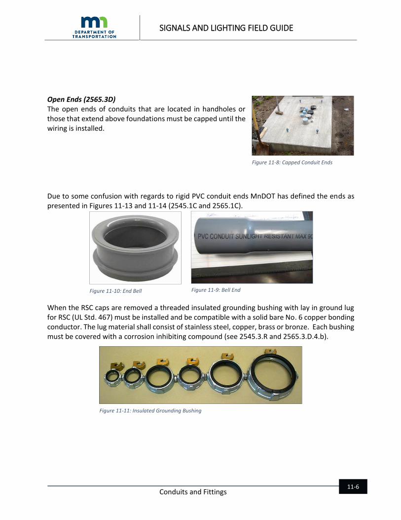
When the RSC caps are removed a threaded insulated grounding bushing with lay in ground lug for RSC (UL Std. 467) must be installed and be compatible with a solid bare No. 6 copper bonding conductor. The lug material shall consist of stainless steel, copper, brass or bronze. Each bushing must be covered with a corrosion inhibiting compound (see 2545.3.R and 2565.3.D.4.b).
Figure 11-8: Capped Conduit Ends
Figure 11-9: Bell End Figure 11-10: End Bell
Figure 11-11: Insulated Grounding Bushing

SIGNALS AND LIGHTING FIELD GUIDE
Conduits and Fittings 11-7
The open ends of conduits in a cabinet or foundation must be sealed in accordance with 2565.3D.2.b.
After the installation of the cables and conductors use a duct seal compound NRTL classified under general use tapes. This prevents moisture from entering the cabinet or pole. The sealant also helps in preventing rodents from entering the foundation through the conduit system.
RSC Joints (2565.3D) When standard length RSC conduit is cut the end must be threaded and reamed to remove burrs and rough edges. Field cuts must be made square and true so that all ends joined by coupling butt together for the full circumference. This provides an electrical bonding and grounding connection throughout the entire length of the conduit run.
If the galvanized coating on the conduit is damaged during handling or installation, the damaged areas must be painted with MnDOT approved paint to the satisfaction of the engineer.
Existing Conduit (2565.3D) If the existing underground conduit is incorporated into a new traffic control signal or lighting system, it must be cleaned and blown out with compressed air before the new wires are installed. If a new handhole is installed into an existing conduit run, the conduit must be cut, threaded and extended into the new handhole as directed by the engineer. A new bushing with an integral lug and ground wire must be installed and the sides of the handhole must be made water tight before the installation of any new wires. Thread less couplings and bushings are not permitted unless otherwise authorized by the engineer.
Figure 11-12: Conduit Duct Seal Compound
Figure 11-13: Threading and Reaming the RSC Conduit End
Figure 11-18: Existing Underground Conduit

SIGNALS AND LIGHTING FIELD GUIDE
Conduits and Fittings 11-8
Expansion and Deflection/Expansion Fittings for Conduits used on Bridges (2565.3D.7 & 3839) Because bridges are subjected to flexing, expansion and contraction, special PVC coated expansion and expansion/deflection conduit fittings as well as hangers are required. Improper installation of conduits can cause severe damage to the electrical system and may cause damage to the bridge structure itself. The expansion fitting provides eight inches of linear movement. The deflection/expansion fitting provides 3/4 of an inch of movement in any direction.
MnDOT requires contractors to obtain a separate installation certification training from at least one PVC coated RSC conduit manufacturer.
Repair of damaged PVC coating shall be made in accordance with the conduit manufacturer’s repair requirements.
All conduits must be attached to bridge as specified in the contract documents.
11.2 Chapter 11 Resources
MnDOT Standard Specifications for Construction 3801, 3803, 2565.3D, 2545.3G.2, 2545.1C, 2565.1C, 2545.3.R, 2565.3.D.4.b, 2565.3D.7 & 3839
National Electrical Code (NEC)
Figure 11-19: Expansion Fitting
Figure 11-14: Deflection/Expansion Fitting