Chapter 11: Applications and Processing of Metal Alloys
119
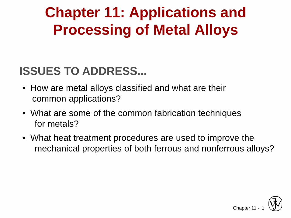
Chapter 11 - 1 Chapter 11: Applications and Processing of Metal Alloys ISSUES TO ADDRESS... • How are metal alloys classified and what are their common applications? • What are some of the common fabrication techniques for metals? • What heat treatment procedures are used to improve the mechanical properties of both ferrous and nonferrous alloys?
Transcript of Chapter 11: Applications and Processing of Metal Alloys
Chapter 11 - 1
Chapter 11: Applications and Processing of Metal Alloys
ISSUES TO ADDRESS...• How are metal alloys classified and what are their
common applications?• What are some of the common fabrication techniques
for metals?• What heat treatment procedures are used to improve the
mechanical properties of both ferrous and nonferrous alloys?
Chapter 11 - 2
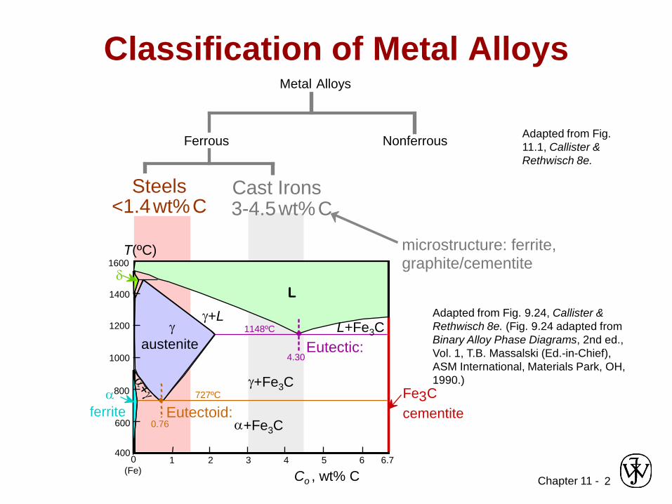
Adapted from Fig. 9.24, Callister & Rethwisch 8e. (Fig. 9.24 adapted from Binary Alloy Phase Diagrams, 2nd ed., Vol. 1, T.B. Massalski (Ed.-in-Chief), ASM International, Materials Park, OH, 1990.)
Adapted from Fig. 11.1, Callister & Rethwisch 8e.
Classification of Metal AlloysMetal Alloys
Steels
Ferrous Nonferrous
Cast Irons<1.4wt%C 3-4.5wt%CSteels
<1.4wt%CCast Irons3-4.5wt%C
Fe3C cementite
1600
1400
1200
1000
800
600
4000 1 2 3 4 5 6 6.7
L
γaustenite
γ+L
γ+Fe3Cα
ferriteα+Fe3C
L+Fe3C
δ
(Fe) Co , wt% C
Eutectic:
Eutectoid:0.76
4.30
727ºC
1148ºC
T(ºC) microstructure: ferrite,graphite/cementite

Chapter 11 - 3Based on data provided in Tables 11.1(b), 11.2(b), 11.3, and 11.4, Callister & Rethwisch 8e.
SteelsLow Alloy High Alloy
low carbon <0.25wt%C
Med carbon0.25-0.6wt%C
high carbon 0.6-1.4wt%C
Uses auto struc. sheet
bridges towers press. vessels
crank shafts bolts hammers blades
pistons gears wear applic.
wear applic.
drills saws dies
high T applic. turbines furnaces
Very corros. resistant
Example 1010 4310 1040 4340 1095 4190 304, 409
Additions none Cr,V Ni, Mo none Cr, Ni
Mo none Cr, V, Mo, W Cr, Ni, Mo
plain HSLA plain heat treatable plain tool stainlessName
Hardenability 0 + + ++ ++ +++ variesTS - 0 + ++ + ++ variesEL + + 0 - - -- ++
increasing strength, cost, decreasing ductility

Chapter 11 - 4
Refinement of Steel from Ore
Iron OreCoke
Limestone
3CO+Fe2O3 →2Fe+3CO2
C+O2 →CO2
CO2 +C→ 2CO
CaCO3 → CaO+CO2CaO + SiO2 + Al2O3 → slag
purification
reduction of iron ore to metal
heat generation
Molten iron
BLAST FURNACE
slagair
layers of cokeand iron ore
gasrefractory vessel
Chapter 11 - 5
Ferrous AlloysIron-based alloys
Nomenclature for steels (AISI/SAE)10xx Plain Carbon Steels11xx Plain Carbon Steels (resulfurized for machinability) 15xx Mn (1.00 - 1.65%)40xx Mo (0.20 ~ 0.30%)43xx Ni (1.65 - 2.00%), Cr (0.40 - 0.90%), Mo (0.20 - 0.30%)44xx Mo (0.5%)
where xx is wt% C x 100example: 1060 steel – plain carbon steel with 0.60 wt% C
Stainless Steel >11% Cr
• Steels• Cast Irons
Chapter 11 - 6
Cast Irons• Ferrous alloys with > 2.1 wt% C
– more commonly 3 - 4.5 wt% C• Low melting – relatively easy to cast• Generally brittle
• Cementite decomposes to ferrite + graphiteFe3C 3 Fe (α) + C (graphite)
– generally a slow process
Chapter 11 - 7
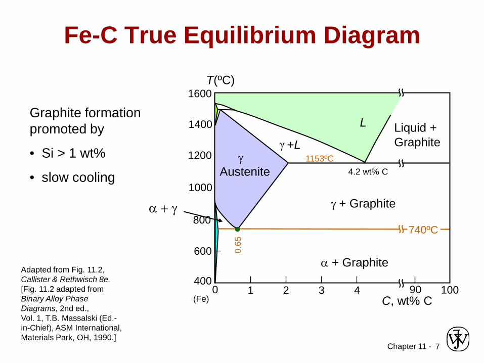
Fe-C True Equilibrium Diagram
Graphite formation promoted by
• Si > 1 wt%
• slow cooling
Adapted from Fig. 11.2, Callister & Rethwisch 8e.[Fig. 11.2 adapted from Binary Alloy Phase Diagrams, 2nd ed.,Vol. 1, T.B. Massalski (Ed.-in-Chief), ASM International, Materials Park, OH, 1990.]
1600
1400
1200
1000
800
600
4000 1 2 3 4 90
L
γ +L
α + Graphite
Liquid +Graphite
(Fe) C, wt% C
0.65
740ºC
T(ºC)
γ + Graphite
100
1153ºCγAustenite 4.2 wt% C
α + γ
Chapter 11 - 8
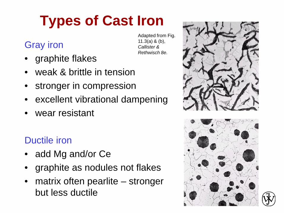
Types of Cast IronGray iron• graphite flakes• weak & brittle in tension• stronger in compression• excellent vibrational dampening• wear resistant
Ductile iron• add Mg and/or Ce• graphite as nodules not flakes• matrix often pearlite – stronger
but less ductile
Adapted from Fig. 11.3(a) & (b), Callister & Rethwisch 8e.
Chapter 11 - 9
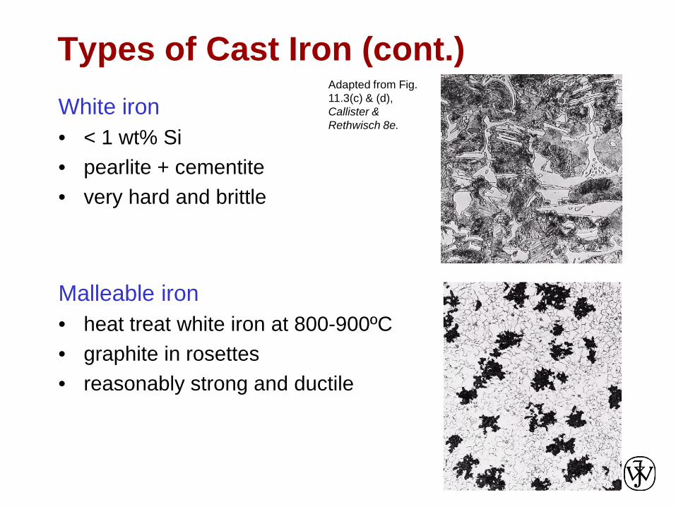
Types of Cast Iron (cont.)White iron• < 1 wt% Si• pearlite + cementite• very hard and brittle
Malleable iron• heat treat white iron at 800-900ºC• graphite in rosettes• reasonably strong and ductile
Adapted from Fig. 11.3(c) & (d), Callister & Rethwisch 8e.

Chapter 11 - 10
Types of Cast Iron (cont.)Compacted graphite iron• relatively high thermal conductivity• good resistance to thermal shock• lower oxidation at elevated
temperatures
Adapted from Fig. 11.3(e), Callister & Rethwisch 8e.

Chapter 11 - 11
Production of Cast Irons
Adapted from Fig.11.5, Callister & Rethwisch 8e.

Chapter 11 - 12
Limitations of Ferrous Alloys
1) Relatively high densities2) Relatively low electrical conductivities3) Generally poor corrosion resistance
Chapter 11 - 13Based on discussion and data provided in Section 11.3, Callister & Rethwisch 3e.
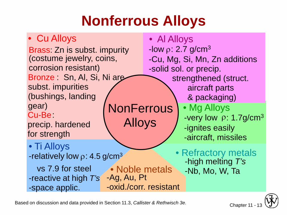
Nonferrous Alloys
NonFerrous Alloys
• Al Alloys-low ρ: 2.7 g/cm3
-Cu, Mg, Si, Mn, Zn additions -solid sol. or precip.
strengthened (struct. aircraft parts & packaging)
• Mg Alloys-very low ρ: 1.7g/cm3
-ignites easily -aircraft, missiles
• Refractory metals-high melting T’s-Nb, Mo, W, Ta• Noble metals
-Ag, Au, Pt -oxid./corr. resistant
• Ti Alloys-relatively low ρ: 4.5 g/cm3
vs 7.9 for steel-reactive at high T’s-space applic.
• Cu AlloysBrass: Zn is subst. impurity(costume jewelry, coins, corrosion resistant)Bronze : Sn, Al, Si, Ni are subst. impurities (bushings, landing gear)Cu-Be: precip. hardened for strength

Chapter 11 - 14
Metal Fabrication• How do we fabricate metals?
– Blacksmith - hammer (forged)– Cast molten metal into mold
• Forming Operations – Rough stock formed to final shape
Hot working vs. Cold working• Deformation temperature
high enough for recrystallization
• Large deformations
• Deformation belowrecrystallization temperature
• Strain hardening occurs• Small deformations

Chapter 11 - 15
FORMING
roll
AoAd
roll
• Rolling (Hot or Cold Rolling)(I-beams, rails, sheet & plate)
Ao Ad
force
dieblank
force
• Forging (Hammering; Stamping)(wrenches, crankshafts)
often atelev. T
Adapted from Fig. 11.8, Callister & Rethwisch 8e.
Metal Fabrication Methods (i)
ram billet
container
containerforce die holder
die
Ao
Adextrusion
• Extrusion(rods, tubing)
ductile metals, e.g. Cu, Al (hot)
tensile force
AoAddie
die
• Drawing(rods, wire, tubing)
die must be well lubricated & clean
CASTING MISCELLANEOUS

Chapter 11 - 16
FORMING CASTING
Metal Fabrication Methods (ii)
• Casting- mold is filled with molten metal– metal melted in furnace, perhaps alloying
elements added, then cast in a mold – common and inexpensive– gives good production of shapes– weaker products, internal defects– good option for brittle materials
MISCELLANEOUS

Chapter 11 - 17
• Sand Casting(large parts, e.g.,auto engine blocks)
Metal Fabrication Methods (iii)
• What material will withstand T >1600ºCand is inexpensive and easy to mold?
• Answer: sand!!!
• To create mold, pack sand around form (pattern) of desired shape
Sand Sand
molten metal
FORMING CASTING MISCELLANEOUS

Chapter 11 - 18
• Stage I — Mold formed by pouring plaster of paris around wax pattern. Plaster allowed to harden.
• Stage II — Wax is melted and then poured from mold—hollow mold cavity remains.
• Stage III — Molten metal is poured into mold and allowed to solidify.
Metal Fabrication Methods (iv)
FORMING CASTING MISCELLANEOUS• Investment Casting
(low volume, complex shapese.g., jewelry, turbine blades)
wax I
II
III
Chapter 11 - 19
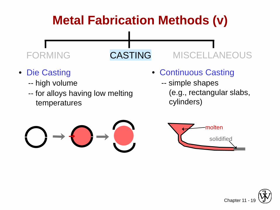
Metal Fabrication Methods (v)
• Continuous Casting-- simple shapes
(e.g., rectangular slabs, cylinders)
molten
solidified
FORMING CASTING MISCELLANEOUS
• Die Casting-- high volume-- for alloys having low melting
temperatures

Chapter 11 - 20
MISCELLANEOUSCASTING
Metal Fabrication Methods (vi)
• Powder Metallurgy(metals w/low ductilities)
pressure
heat
point contact at low T
densificationby diffusion at higher T
area contact
densify
• Welding(when fabrication of one large part is impractical)
• Heat-affected zone:(region in which themicrostructure has beenchanged).
Adapted from Fig. 11.9, Callister & Rethwisch 8e.(Fig. 11.9 from Iron Castings Handbook, C.F. Walton and T.J. Opar (Ed.), 1981.)
piece 1 piece 2
fused base metal
filler metal (melted)base metal (melted)
unaffectedunaffectedheat-affected zone
FORMING

Chapter 11 - 21
Annealing: Heat to Tanneal, then cool slowly.
Based on discussion in Section 11.7, Callister & Rethwisch 8e.
Thermal Processing of Metals
Types of Annealing
• Process Anneal:Negate effects of cold working by (recovery/
recrystallization)
• Stress Relief: Reducestresses resulting from:
- plastic deformation - nonuniform cooling - phase transform.
• Normalize (steels): Deformsteel with large grains. Then heattreat to allow recrystallization and formation of smaller grains.
• Full Anneal (steels): Make soft steels for good forming. Heat to get γ, then furnace-coolto obtain coarse pearlite.
• Spheroidize (steels): Make very soft steels for good machining. Heat just
below Teutectoid & hold for15-25 h.
Chapter 11 - 22
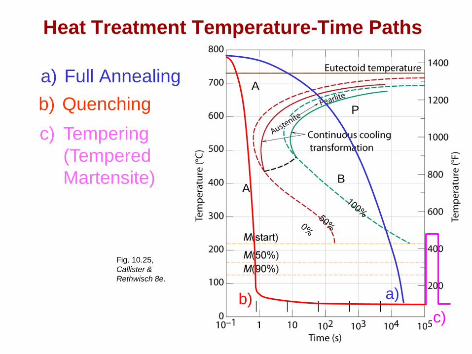
a) Full Annealingb) Quenching
Heat Treatment Temperature-Time Paths
c)
c) Tempering (Tempered Martensite)
P
B
A
A
a)b)
Fig. 10.25,Callister & Rethwisch 8e.

Chapter 11 - 23
Hardenability -- Steels• Hardenability – measure of the ability to form martensite• Jominy end quench test used to measure hardenability.
• Plot hardness versus distance from the quenched end.
Adapted from Fig. 11.11, Callister & Rethwisch 8e. (Fig. 11.11 adapted from A.G. Guy, Essentials of Materials Science, McGraw-Hill Book Company, New York, 1978.)
Adapted from Fig. 11.12, Callister & Rethwisch 8e.
24ºC water
specimen (heated to γphase field)
flat ground
Rockwell Chardness tests
Har
dnes
s, H
RC
Distance from quenched end

Chapter 11 - 24
• The cooling rate decreases with distance from quenched end.
Adapted from Fig. 11.13, Callister & Rethwisch 8e. (Fig. 11.13 adapted from H. Boyer (Ed.) Atlas of Isothermal Transformation and Cooling Transformation Diagrams, American Society for Metals, 1977, p. 376.)
Reason Why Hardness Changes with Distance
distance from quenched end (in)Har
dnes
s, H
RC
20
40
60
0 1 2 3
600
400
200A → M
0.1 1 10 100 1000
T(ºC)
M(start)
Time (s)
0
0%100%
M(finish)

Chapter 11 - 25
Hardenability vs Alloy Composition• Hardenability curves for
five alloys each with, C = 0.4 wt% C
• "Alloy Steels"(4140, 4340, 5140, 8640)-- contain Ni, Cr, Mo
(0.2 to 2 wt%)-- these elements shift
the "nose" to longer times (from A to B)
-- martensite is easierto form
Adapted from Fig. 11.14, Callister & Rethwisch 8e. (Fig. 11.14 adapted from figure furnished courtesy Republic Steel Corporation.)
Cooling rate (ºC/s)
Har
dnes
s, H
RC
20
40
60
100 20 30 40 50Distance from quenched end (mm)
210100 3
41408640
5140
50
80
100
%M4340
T(ºC)
10-1 10 103 1050
200
400
600
800
Time (s)
M(start)M(90%)
BA
TE

Chapter 11 - 26
• Effect of quenching medium:Medium
airoil
water
Severity of Quenchlow
moderatehigh
Hardnesslow
moderatehigh
• Effect of specimen geometry:When surface area-to-volume ratio increases:
-- cooling rate throughout interior increases-- hardness throughout interior increases
Positioncentersurface
Cooling ratelowhigh
Hardnesslowhigh
Influences of Quenching Medium & Specimen Geometry

Chapter 11 - 27
0 10 20 30 40 50wt% Cu
Lα+Lα
α+θθ
θ+L
300
400
500
600
700
(Al)
T(ºC)
composition range available for precipitation hardening
CuAl2
A
Adapted from Fig. 11.24, Callister & Rethwisch 8e. (Fig. 11.24 adapted from J.L. Murray, International Metals Review 30, p.5, 1985.)
Precipitation Hardening• Particles impede dislocation motion.• Ex: Al-Cu system• Procedure:
Adapted from Fig. 11.22, Callister & Rethwisch 8e.
-- Pt B: quench to room temp.(retain α solid solution)
-- Pt C: reheat to nucleatesmall θ particles withinα phase.
• Other alloys that precipitationharden:• Cu-Be• Cu-Sn• Mg-Al
Temp.
Time
-- Pt A: solution heat treat(get α solid solution)
Pt A (sol’n heat treat)
B
Pt B
C
Pt C (precipitate θ)

Chapter 11 - 28
• 2014 Al Alloy:
• Maxima on TS curves.• Increasing T accelerates
process.
Adapted from Fig. 11.27, Callister & Rethwisch 8e. (Fig. 11.27 adapted from Metals Handbook: Properties and Selection: Nonferrous Alloys and Pure Metals, Vol. 2, 9th ed., H. Baker (Managing Ed.), American Society for Metals, 1979. p. 41.)
Influence of Precipitation Heat Treatment on TS, %EL
precipitation heat treat time
tens
ile s
treng
th (M
Pa)
200
300
400
100 1min 1h 1day 1mo 1yr
204ºC149ºC
• Minima on %EL curves.
%E
L(2
in s
ampl
e)10
20
30
0 1min 1h 1day 1mo 1yr
204ºC 149ºC
precipitation heat treat time
Chapter 11 - 29
• Ferrous alloys: steels and cast irons• Non-ferrous alloys:
-- Cu, Al, Ti, and Mg alloys; refractory alloys; and noble metals.• Metal fabrication techniques:
-- forming, casting, miscellaneous.• Hardenability of metals
-- measure of ability of a steel to be heat treated.-- increases with alloy content.
• Precipitation hardening--hardening, strengthening due to formation of
precipitate particles.--Al, Mg alloys precipitation hardenable.
Summary

Chapter 12 - 1
Chapter 12: Structures & Properties of Ceramics
ISSUES TO ADDRESS...• How do the crystal structures of ceramic materials
differ from those for metals?• How do point defects in ceramics differ from those
defects found in metals?• How are impurities accommodated in the ceramic lattice?
• How are the mechanical properties of ceramics measured, and how do they differ from those for metals?
• In what ways are ceramic phase diagrams different from phase diagrams for metals?
Chapter 12 - 2
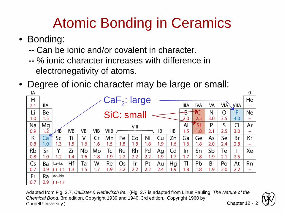
• Bonding:-- Can be ionic and/or covalent in character.-- % ionic character increases with difference in
electronegativity of atoms.
Adapted from Fig. 2.7, Callister & Rethwisch 8e. (Fig. 2.7 is adapted from Linus Pauling, The Nature of the Chemical Bond, 3rd edition, Copyright 1939 and 1940, 3rd edition. Copyright 1960 byCornell University.)
• Degree of ionic character may be large or small:
Atomic Bonding in Ceramics
SiC: smallCaF2: large

Chapter 12 - 3
Ceramic Crystal Structures
Oxide structures– oxygen anions larger than metal cations– close packed oxygen in a lattice (usually FCC)– cations fit into interstitial sites among oxygen ions
Chapter 12 - 4
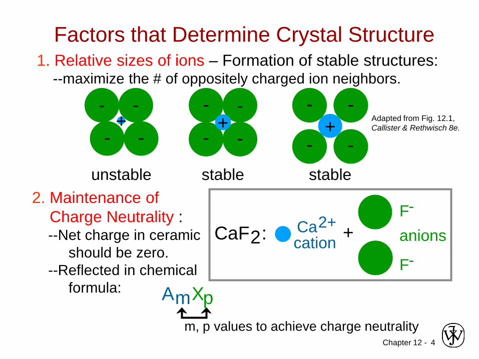
Factors that Determine Crystal Structure1. Relative sizes of ions – Formation of stable structures:
--maximize the # of oppositely charged ion neighbors.
Adapted from Fig. 12.1, Callister & Rethwisch 8e.
- -
- -+
unstable
- -
- -+
stable
- -
- -+
stable2. Maintenance of
Charge Neutrality :--Net charge in ceramic
should be zero.--Reflected in chemical
formula:
CaF2: Ca2+cation
F-
F-
anions+
AmXpm, p values to achieve charge neutrality

Chapter 12 - 5
• Coordination # increases with
Coordination # and Ionic Radii
Adapted from Table 12.2, Callister & Rethwisch 8e.
2
rcationranion
Coord #
< 0.155
0.155 - 0.225
0.225 - 0.414
0.414 - 0.732
0.732 - 1.0
3
4
6
8
linear
triangular
tetrahedral
octahedral
cubic
Adapted from Fig. 12.2, Callister & Rethwisch 8e.
Adapted from Fig. 12.3, Callister & Rethwisch 8e.
Adapted from Fig. 12.4, Callister & Rethwisch 8e.
ZnS (zinc blende)
NaCl(sodium chloride)
CsCl(cesium chloride)
rcationranion
To form a stable structure, how many anions cansurround around a cation?

Chapter 12 - 6
Computation of Minimum Cation-Anion Radius Ratio
• Determine minimum rcation/ranion for an octahedral site (C.N. = 6)
a = 2ranion
2ranion + 2rcation = 2 2ranion
ranion + rcation = 2ranion
rcation = ( 2 −1)ranion
arr 222 cationanion =+
414.012anion
cation =−=rr

Chapter 12 - 7
Bond HybridizationBond Hybridization is possible when there is significant
covalent bonding– hybrid electron orbitals form– For example for SiC
• XSi = 1.8 and XC = 2.5
% ionic character = 100 {1- exp[-0.25(XSi − XC)2]} = 11.5%
• ~ 89% covalent bonding• Both Si and C prefer sp3 hybridization• Therefore, for SiC, Si atoms occupy tetrahedral sites

Chapter 12 - 8
• On the basis of ionic radii, what crystal structurewould you predict for FeO?
• Answer:
550014000770
anion
cation
...
rr
=
=
based on this ratio,-- coord # = 6 because
0.414 < 0.550 < 0.732
-- crystal structure is NaClData from Table 12.3, Callister & Rethwisch 8e.
Example Problem: Predicting the Crystal Structure of FeO
Ionic radius (nm)0.0530.0770.0690.100
0.1400.1810.133
Cation
Anion
Al3+
Fe2+
Fe3+
Ca2+
O2-
Cl-
F-
Chapter 12 - 9
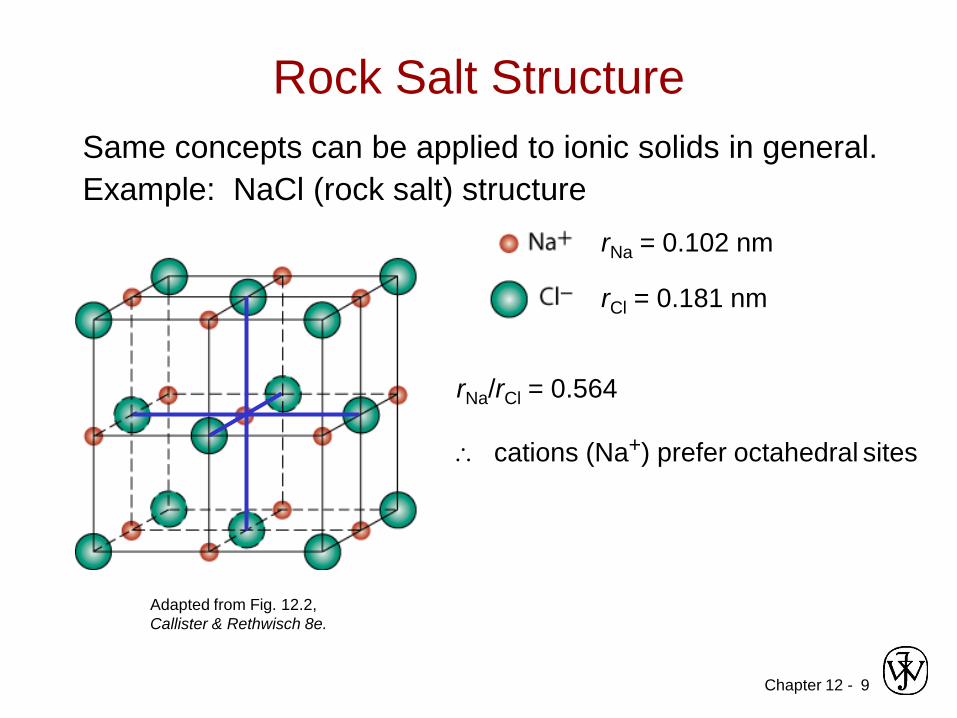
Rock Salt StructureSame concepts can be applied to ionic solids in general. Example: NaCl (rock salt) structure
rNa = 0.102 nm
rNa/rCl = 0.564
∴ cations (Na+) prefer octahedral sites
Adapted from Fig. 12.2, Callister & Rethwisch 8e.
rCl = 0.181 nm

Chapter 12 - 10
MgO and FeO
O2- rO = 0.140 nm
Mg2+ rMg = 0.072 nm
rMg/rO = 0.514
∴ cations prefer octahedral sites
So each Mg2+ (or Fe2+) has 6 neighbor oxygen atoms
Adapted from Fig. 12.2, Callister & Rethwisch 8e.
MgO and FeO also have the NaCl structure

Chapter 12 - 11
AX Crystal Structures
939.0181.0170.0
Cl
Cs ==−
+
r
r
Adapted from Fig. 12.3, Callister & Rethwisch 8e.
Cesium Chloride structure:
∴ Since 0.732 < 0.939 < 1.0, cubic sites preferred
So each Cs+ has 8 neighbor Cl-
AX–Type Crystal Structures include NaCl, CsCl, and zinc blende

Chapter 12 - 12
AX2 Crystal Structures
• Calcium Fluorite (CaF2)• Cations in cubic sites
• UO2, ThO2, ZrO2, CeO2
• Antifluorite structure –positions of cations and anions reversed
Adapted from Fig. 12.5, Callister & Rethwisch 8e.
Fluorite structure

Chapter 12 - 13
ABX3 Crystal Structures
Adapted from Fig. 12.6, Callister & Rethwisch 8e.
• Perovskite structure
Ex: complex oxide BaTiO3
Chapter 12 -
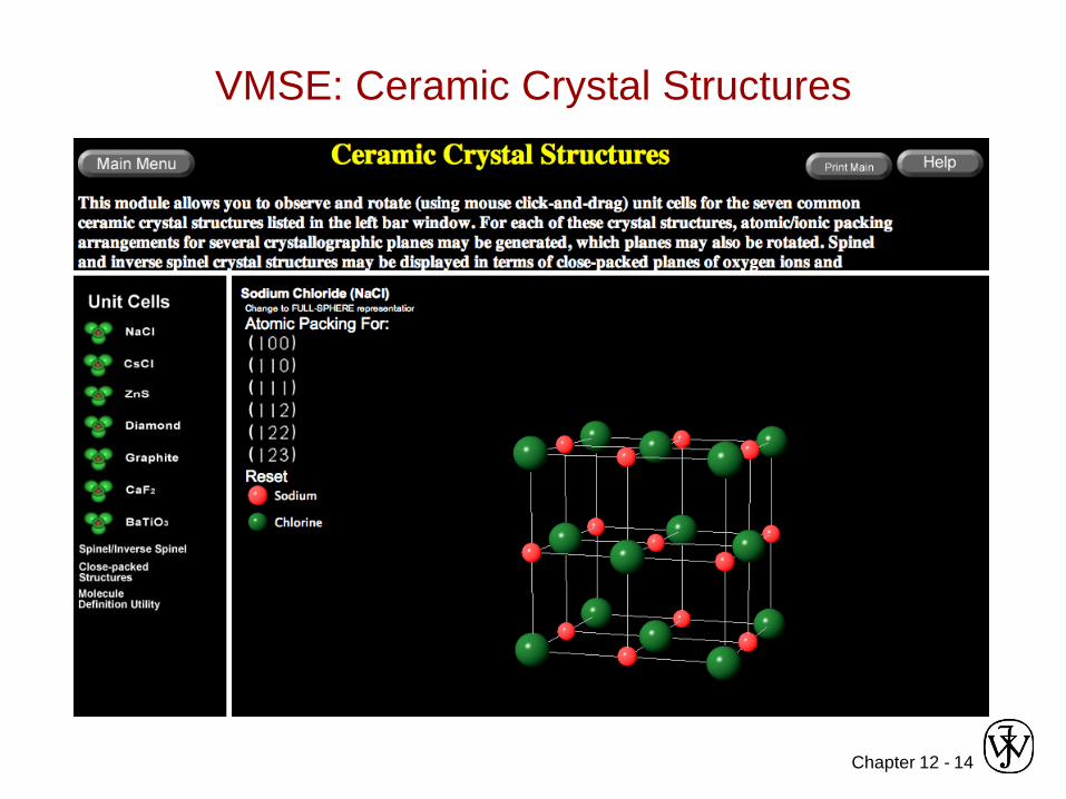
VMSE: Ceramic Crystal Structures
14
Chapter 12 - 15
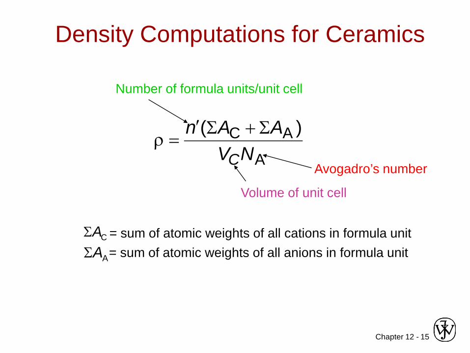
Density Computations for Ceramics
A
AC )(NV
AAn
C
Σ+Σ′=ρ
Number of formula units/unit cell
Volume of unit cell
Avogadro’s number
= sum of atomic weights of all anions in formula unit
ΣAA
ΣAC = sum of atomic weights of all cations in formula unit

Chapter 12 - 16
Silicate CeramicsMost common elements on earth are Si & O
• SiO2 (silica) polymorphic forms are quartz, crystobalite, & tridymite
• The strong Si-O bonds lead to a high melting temperature (1710ºC) for this material
Si4+
O2-
Adapted from Figs. 12.9-10, Callister & Rethwisch 8e crystobalite

Chapter 12 - 17
Bonding of adjacent SiO44- accomplished by the
sharing of common corners, edges, or faces
Silicates
Mg2SiO4 Ca2MgSi2O7
Adapted from Fig. 12.12, Callister & Rethwisch 8e.
Presence of cations such as Ca2+, Mg2+, & Al3+
1. maintain charge neutrality, and2. ionically bond SiO4
4- to one another
Chapter 12 - 18
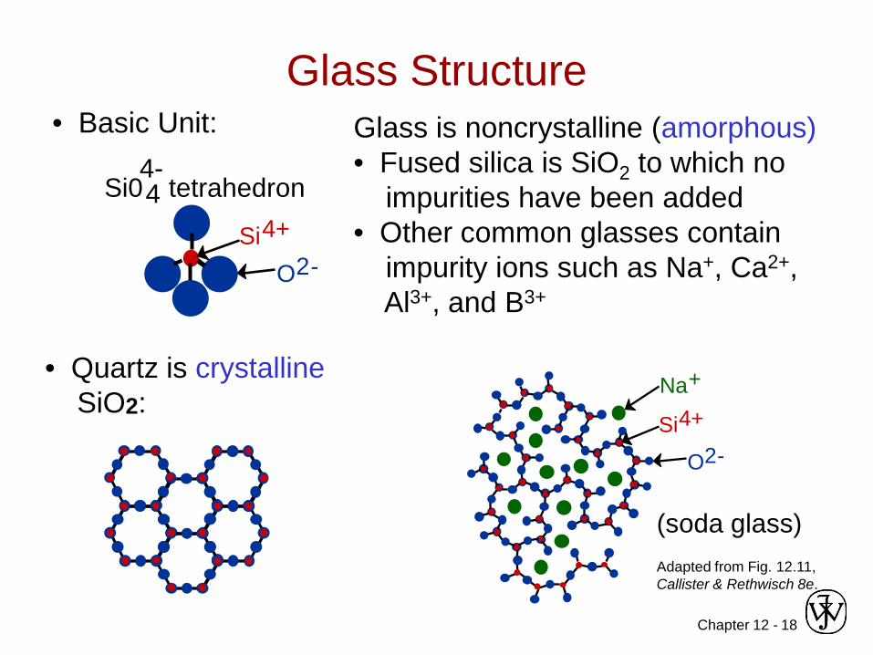
• Quartz is crystallineSiO2:
• Basic Unit: Glass is noncrystalline (amorphous)• Fused silica is SiO2 to which no
impurities have been added• Other common glasses contain
impurity ions such as Na+, Ca2+, Al3+, and B3+
(soda glass)Adapted from Fig. 12.11, Callister & Rethwisch 8e.
Glass Structure
Si04 tetrahedron4-
Si4+
O2-
Si4+Na+
O2-

Chapter 12 - 19
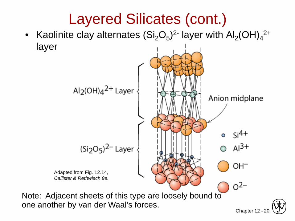
Layered Silicates• Layered silicates (e.g., clays, mica, talc)
– SiO4 tetrahedra connected together to form 2-D plane
• A net negative charge is associated with each (Si2O5)2- unit
• Negative charge balanced by adjacent plane rich in positively charged cations
Adapted from Fig. 12.13, Callister & Rethwisch 8e.
Chapter 12 - 20
• Kaolinite clay alternates (Si2O5)2- layer with Al2(OH)42+
layer
Layered Silicates (cont.)
Note: Adjacent sheets of this type are loosely bound to one another by van der Waal’s forces.
Adapted from Fig. 12.14, Callister & Rethwisch 8e.

Chapter 12 - 21
Polymorphic Forms of CarbonDiamond– tetrahedral bonding of
carbon• hardest material known• very high thermal
conductivity– large single crystals –
gem stones– small crystals – used to
grind/cut other materials – diamond thin films
• hard surface coatings –used for cutting tools, medical devices, etc.
Adapted from Fig. 12.15, Callister & Rethwisch 8e.

Chapter 12 - 22
Polymorphic Forms of Carbon (cont)Graphite– layered structure – parallel hexagonal arrays of
carbon atoms
– weak van der Waal’s forces between layers– planes slide easily over one another -- good
lubricant
Adapted from Fig. 12.17, Callister & Rethwisch 8e.

Chapter 12 - 23
Polymorphic Forms of Carbon (cont)Fullerenes and Nanotubes
• Fullerenes – spherical cluster of 60 carbon atoms, C60
– Like a soccer ball • Carbon nanotubes – sheet of graphite rolled into a tube
– Ends capped with fullerene hemispheres
Adapted from Figs. 12.18 & 12.19, Callister & Rethwisch 8e.
Chapter 12 - 24
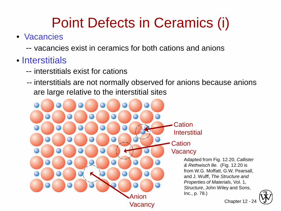
• Vacancies-- vacancies exist in ceramics for both cations and anions
• Interstitials-- interstitials exist for cations-- interstitials are not normally observed for anions because anions
are large relative to the interstitial sites
Adapted from Fig. 12.20, Callister & Rethwisch 8e. (Fig. 12.20 is from W.G. Moffatt, G.W. Pearsall, and J. Wulff, The Structure and Properties of Materials, Vol. 1, Structure, John Wiley and Sons, Inc., p. 78.)
Point Defects in Ceramics (i)
Cation Interstitial
Cation Vacancy
Anion Vacancy
Chapter 12 - 25
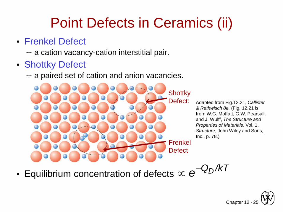
• Frenkel Defect-- a cation vacancy-cation interstitial pair.
• Shottky Defect-- a paired set of cation and anion vacancies.
• Equilibrium concentration of defects
Adapted from Fig.12.21, Callister & Rethwisch 8e. (Fig. 12.21 is from W.G. Moffatt, G.W. Pearsall, and J. Wulff, The Structure and Properties of Materials, Vol. 1, Structure, John Wiley and Sons, Inc., p. 78.)
Point Defects in Ceramics (ii)
Shottky Defect:
Frenkel Defect
/kTQDe−∝

Chapter 12 - 26
• Electroneutrality (charge balance) must be maintained when impurities are present
• Ex: NaCl
Imperfections in Ceramics
Na+ Cl-• Substitutional cation impurity
without impurity Ca2+ impurity with impurity
Ca2+
Na+
Na+Ca2+
cation vacancy
• Substitutional anion impurity
without impurity O2- impurity
O2-
Cl-
anion vacancy
Cl-
with impurity
Chapter 12 - 27
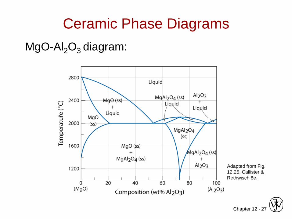
Ceramic Phase DiagramsMgO-Al2O3 diagram:
Adapted from Fig. 12.25, Callister & Rethwisch 8e.
°
Chapter 12 - 28
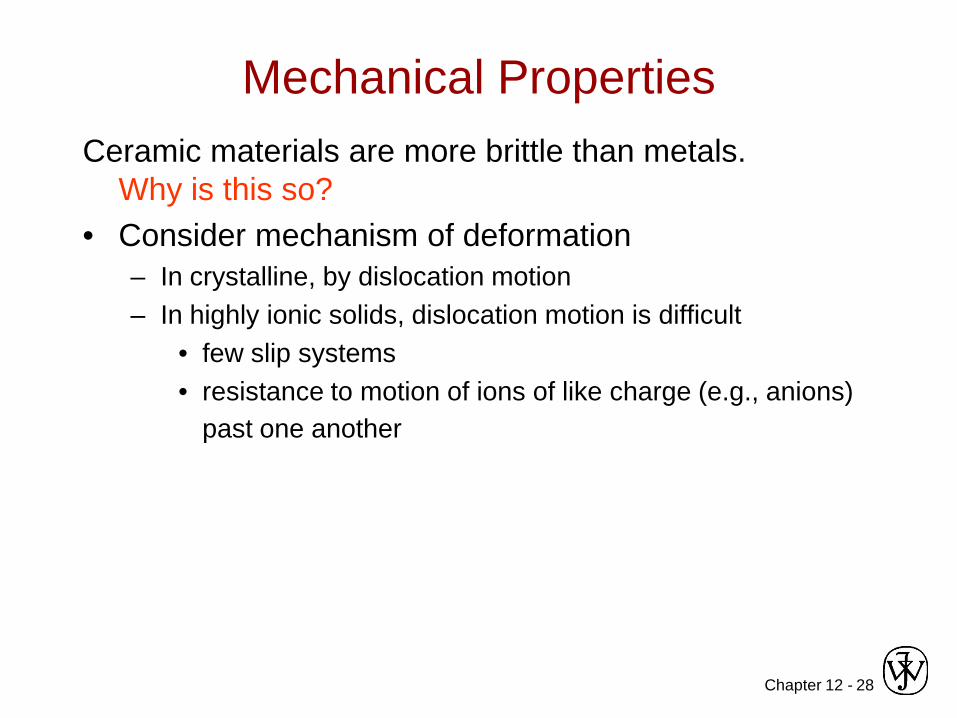
Mechanical PropertiesCeramic materials are more brittle than metals.
Why is this so?• Consider mechanism of deformation
– In crystalline, by dislocation motion– In highly ionic solids, dislocation motion is difficult
• few slip systems• resistance to motion of ions of like charge (e.g., anions)
past one another

Chapter 12 - 29
• Room T behavior is usually elastic, with brittle failure.• 3-Point Bend Testing often used.
-- tensile tests are difficult for brittle materials.
Adapted from Fig. 12.32, Callister & Rethwisch 8e.
Flexural Tests – Measurement of Elastic Modulus
FL/2 L/2
δ = midpoint deflection
cross section
R
b
d
rect. circ.
• Determine elastic modulus according to:F
x
linear-elastic behaviorδ
Fδ
slope =3
3
4bdLFE
δ= (rect. cross section)
4
3
12 RLFEπδ
= (circ. cross section)

Chapter 12 - 30
• 3-point bend test to measure room-T flexural strength.
Adapted from Fig. 12.32, Callister & Rethwisch 8e.
Flexural Tests – Measurement of Flexural Strength
FL/2 L/2
δ = midpoint deflection
cross section
R
b
d
rect. circ.
location of max tension
• Flexural strength: • Typical values:
Data from Table 12.5, Callister & Rethwisch 8e.
Si nitrideSi carbideAl oxideglass (soda-lime)
250-1000100-820275-700
69
30434539369
Material σfs (MPa) E(GPa)
223bd
LFffs =σ (rect. cross section)
(circ. cross section)3RLFf
fsπ
=σ
Chapter 12 - 31
SUMMARY• Interatomic bonding in ceramics is ionic and/or covalent.• Ceramic crystal structures are based on:
-- maintaining charge neutrality-- cation-anion radii ratios.
• Imperfections-- Atomic point: vacancy, interstitial (cation), Frenkel, Schottky-- Impurities: substitutional, interstitial-- Maintenance of charge neutrality
• Room-temperature mechanical behavior – flexural tests-- linear-elastic; measurement of elastic modulus-- brittle fracture; measurement of flexural modulus

Chapter 13 - 1
Chapter 13: Applications and Processing of Ceramics
ISSUES TO ADDRESS...• How do we classify ceramics?
• What are some applications of ceramics?
• How is processing of ceramics different than for metals?

Chapter 13 - 2
Glasses Clay products
Refractories Abrasives Cements Advanced ceramics
-optical -composite reinforce
-containers/ household
-whiteware -structural
-bricks for high T (furnaces)
-sandpaper -cutting -polishing
-composites -structural
-engine rotors valves bearings
-sensorsAdapted from Fig. 13.1 and discussion in Section 13.2-8, Callister & Rethwisch 8e.
Classification of Ceramics
Ceramic Materials

Chapter 13 - 3
tensile force
AoAddie
die
• Die blanks:-- Need wear resistant properties!
• Die surface:-- 4 µm polycrystalline diamond
particles that are sintered onto acemented tungsten carbidesubstrate.
-- polycrystalline diamond gives uniform hardness in all directions to reduce wear.
Adapted from Fig. 11.8(d), Callister & Rethwisch 8e.
Courtesy Martin Deakins, GE Superabrasives, Worthington, OH. Used with permission.
Ceramics Application: Die Blanks
Chapter 13 - 4
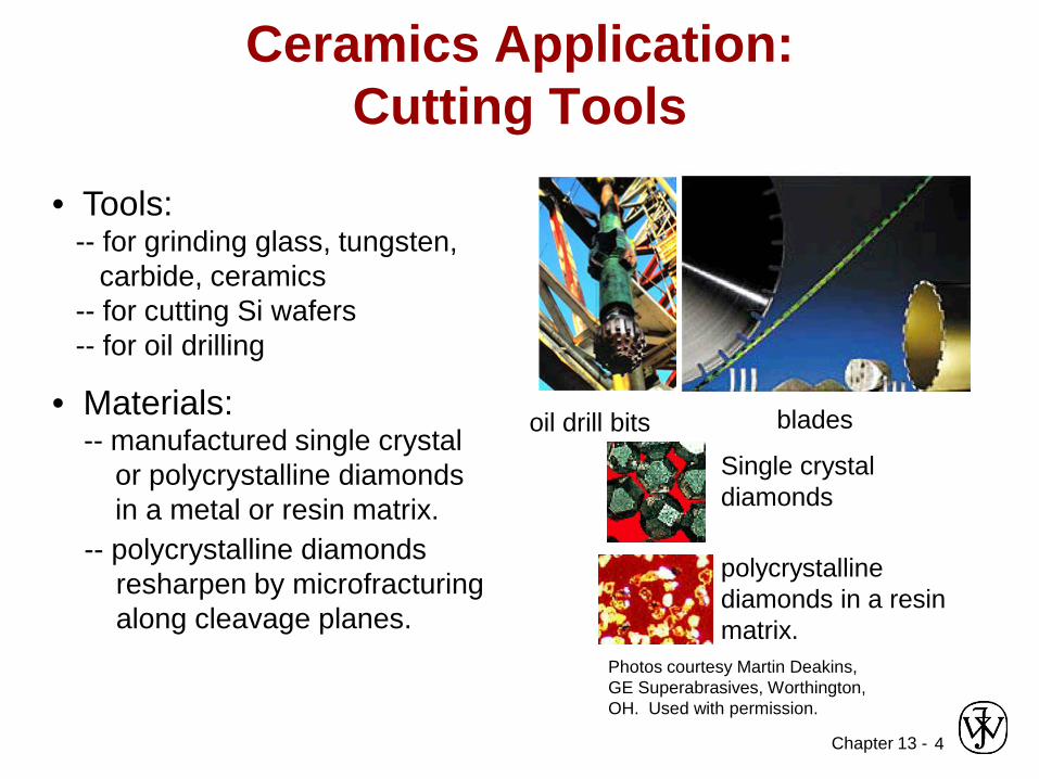
• Tools:-- for grinding glass, tungsten,
carbide, ceramics-- for cutting Si wafers-- for oil drilling
bladesoil drill bits
Single crystal diamonds
polycrystallinediamonds in a resinmatrix.
Photos courtesy Martin Deakins,GE Superabrasives, Worthington,OH. Used with permission.
Ceramics Application: Cutting Tools
• Materials:-- manufactured single crystal
or polycrystalline diamondsin a metal or resin matrix.
-- polycrystalline diamondsresharpen by microfracturingalong cleavage planes.

Chapter 13 - 5
• Example: ZrO2 as an oxygen sensor• Principle: Increase diffusion rate of oxygen
to produce rapid response of sensor signal to change in oxygen concentration
Ceramics Application: Sensors
A substituting Ca2+ ion removes a Zr4+ ion and
an O2- ion.
Ca2+
• Approach:Add Ca impurity to ZrO2:-- increases O2- vacancies-- increases O2- diffusion rate
reference gas at fixed oxygen contentO2-
diffusion
gas with an unknown, higher oxygen content
-+voltage difference produced!
sensor• Operation:
-- voltage difference produced when O2- ions diffuse from the external surface through the sensor to the reference gas surface.
-- magnitude of voltage difference ∝ partial pressure of oxygen at the external surface
Chapter 13 - 6
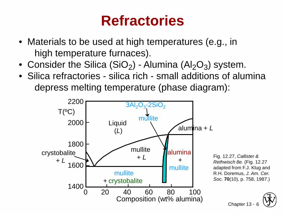
• Materials to be used at high temperatures (e.g., in high temperature furnaces).
• Consider the Silica (SiO2) - Alumina (Al2O3) system.• Silica refractories - silica rich - small additions of alumina
depress melting temperature (phase diagram):
Fig. 12.27, Callister & Rethwisch 8e. (Fig. 12.27 adapted from F.J. Klug and R.H. Doremus, J. Am. Cer. Soc. 70(10), p. 758, 1987.)
Refractories
Composition (wt% alumina)
T(ºC)
1400
1600
1800
2000
2200
20 40 60 80 1000
alumina+
mullite
mullite + L
mulliteLiquid
(L)
mullite+ crystobalite
crystobalite + L
alumina + L
3Al2O3-2SiO2

Chapter 13 - 7
Advanced Ceramics: Materials for Automobile Engines
• Advantages: – Operate at high
temperatures – high efficiencies
– Low frictional losses– Operate without a cooling
system– Lower weights than
current engines
• Disadvantages: – Ceramic materials are
brittle– Difficult to remove internal
voids (that weaken structures)
– Ceramic parts are difficult to form and machine
• Potential candidate materials: Si3N4, SiC, & ZrO2
• Possible engine parts: engine block & piston coatings

Chapter 13 - 8
Advanced Ceramics: Materials for Ceramic Armor
Components:-- Outer facing plates-- Backing sheet
Properties/Materials:-- Facing plates -- hard and brittle
— fracture high-velocity projectile— Al2O3, B4C, SiC, TiB2
-- Backing sheets -- soft and ductile— deform and absorb remaining energy— aluminum, synthetic fiber laminates

Chapter 13 - 9
• Blowing of Glass Bottles:
GLASSFORMING
Adapted from Fig. 13.8, Callister & Rethwisch 8e. (Fig. 13.8 is adapted from C.J. Phillips, Glass: The Miracle Maker, Pittman Publishing Ltd., London.)
Ceramic Fabrication Methods (i)
Gob
Parison mold
Pressing operation
Suspended parison
Finishing mold
Compressed air
• Fiber drawing:
wind up
PARTICULATEFORMING
CEMENTATION
-- glass formed by application of pressure
-- mold is steel with graphite lining
• Pressing: plates, cheap glasses

Chapter 13 -10
Sheet Glass Forming• Sheet forming – continuous casting
– sheets are formed by floating the molten glass on a pool of molten tin
Adapted from Fig. 13.9, Callister & Rethwisch 8e.

Chapter 13 - 11
• Quartz is crystallineSiO2:
• Basic Unit: Glass is noncrystalline (amorphous)• Fused silica is SiO2 to which no
impurities have been added• Other common glasses contain
impurity ions such as Na+, Ca2+, Al3+, and B3+
(soda glass)Adapted from Fig. 12.11, Callister & Rethwisch 8e.
Glass Structure
Si04 tetrahedron4-
Si4+
O2-
Si4+Na+
O2-

Chapter 13 -12
• Specific volume (1/ρ) vs Temperature (T):
• Glasses: -- do not crystallize-- change in slope in spec. vol. curve at
glass transition temperature, Tg-- transparent - no grain boundaries to
scatter light
• Crystalline materials: -- crystallize at melting temp, Tm-- have abrupt change in spec.
vol. at Tm
Adapted from Fig. 13.6, Callister & Rethwisch 8e.
Glass Properties
T
Specific volume
Supercooled Liquid
solid
Tm
Liquid(disordered)
Crystalline (i.e., ordered)
Tg
Glass (amorphous solid)

Chapter 13 -13
Glass Properties: Viscosity
• Viscosity, η: -- relates shear stress (τ) and velocity gradient (dv/dy):
η has units of (Pa-s)
dydv /τ
=η
velocity gradient
dvdy
τ
τ
glass dvdy

Chapter 13 -14
Visc
osity
[Pa-
s]
1102
106
1010
1014
200 600 1000 1400 1800 T(ºC)
Working range: glass-forming carried out
annealing point
Tmelt
strain point
• Viscosity decreases with T
Adapted from Fig. 13.7, Callister & Rethwisch 8e. (Fig. 13.7 is from E.B. Shand, Engineering Glass, Modern Materials, Vol. 6, Academic Press, New York, 1968, p. 262.)
Log Glass Viscosity vs. Temperature
• fused silica: > 99.5 wt% SiO2
• soda-lime glass: 70% SiO2balance Na2O (soda) & CaO (lime)
• Vycor: 96% SiO2, 4% B2O3
• borosilicate (Pyrex): 13% B2O3, 3.5% Na2O, 2.5% Al2O3
Chapter 13 -15
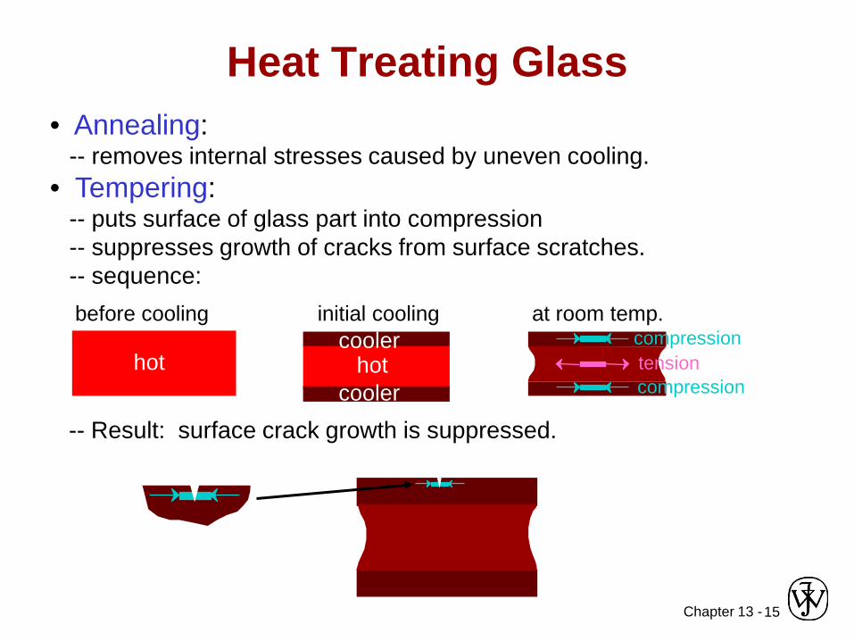
• Annealing:-- removes internal stresses caused by uneven cooling.
• Tempering:-- puts surface of glass part into compression-- suppresses growth of cracks from surface scratches.-- sequence:
Heat Treating Glass
at room temp.
tensioncompression
compression
before cooling
hot
initial cooling
hotcooler
cooler
-- Result: surface crack growth is suppressed.
Chapter 13 -16
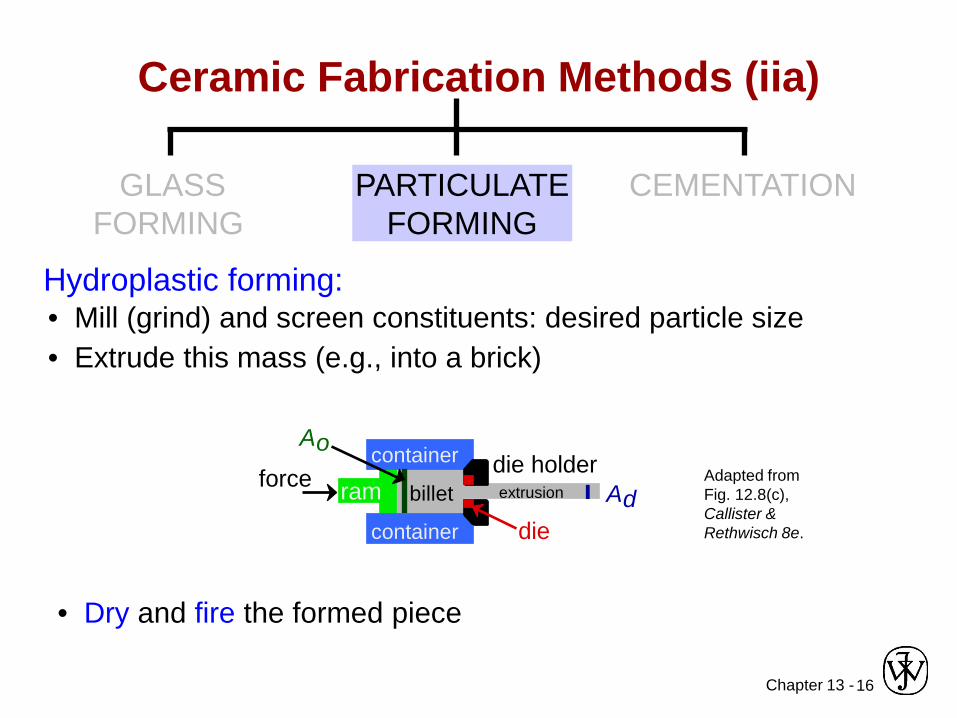
• Mill (grind) and screen constituents: desired particle size• Extrude this mass (e.g., into a brick)
• Dry and fire the formed piece
ram billet
container
containerforce die holder
die
Ao
AdextrusionAdapted from Fig. 12.8(c), Callister & Rethwisch 8e.
Ceramic Fabrication Methods (iia)
GLASSFORMING
PARTICULATEFORMING
CEMENTATION
Hydroplastic forming:

Chapter 13 -17
• Mill (grind) and screen constituents: desired particle size
• Slip casting operation
• Dry and fire the cast piece
Ceramic Fabrication Methods (iia)
solid component
Adapted from Fig. 13.12, Callister & Rethwisch 8e. (Fig. 13.12 is from W.D. Kingery, Introduction to Ceramics, John Wiley and Sons, Inc., 1960.)
hollow component
pour slip into mold
drain mold
“green ceramic”
pour slip into mold
absorb water into mold “green
ceramic”
GLASSFORMING
PARTICULATEFORMING
CEMENTATION
Slip casting:
• Mix with water and other constituents to form slip

Chapter 13 -18
Typical Porcelain Composition
(50%) 1. Clay(25%) 2. Filler – e.g. quartz (finely ground)(25%) 3. Fluxing agent (Feldspar)
-- aluminosilicates plus K+, Na+, Ca+
-- upon firing - forms low-melting-temp. glass

Chapter 13 -19
• Clay is inexpensive• When water is added to clay
-- water molecules fit in between layered sheets
-- reduces degree of van der Waals bonding
-- when external forces applied – clay particles free to move past one another – becomes hydroplastic
• Structure ofKaolinite Clay:
Adapted from Fig. 12.14, Callister & Rethwisch 8e. (Fig. 12.14 is adapted from W.E. Hauth, "Crystal Chemistry of Ceramics", American Ceramic Society Bulletin, Vol. 30 (4), 1951, p. 140.)
Hydroplasticity of Clay
weak van der Waals bonding
charge neutral
charge neutral
Si 4+
Al 3+-OH
O2-
Shear
Shear
Chapter 13 -20
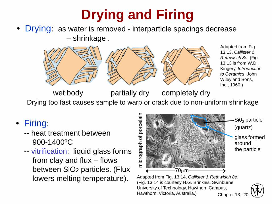
• Drying: as water is removed - interparticle spacings decrease – shrinkage .
Adapted from Fig. 13.13, Callister & Rethwisch 8e. (Fig. 13.13 is from W.D. Kingery, Introduction to Ceramics, John Wiley and Sons, Inc., 1960.)
Drying and Firing
Drying too fast causes sample to warp or crack due to non-uniform shrinkagewet body partially dry completely dry
• Firing:-- heat treatment between
900-1400ºC-- vitrification: liquid glass forms
from clay and flux – flows between SiO2 particles. (Flux lowers melting temperature). Adapted from Fig. 13.14, Callister & Rethwisch 8e.
(Fig. 13.14 is courtesy H.G. Brinkies, Swinburne University of Technology, Hawthorn Campus, Hawthorn, Victoria, Australia.)
Si02 particle(quartz)
glass formed around the particle
mic
rogr
aph
of p
orce
lain
70µm
Chapter 13 -21
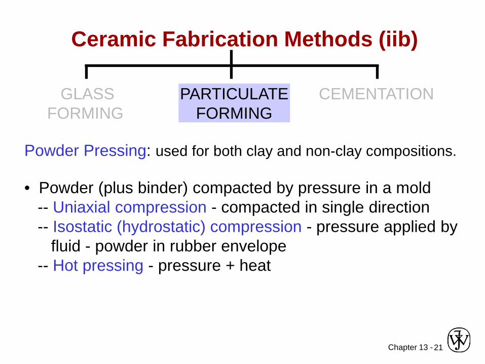
Powder Pressing: used for both clay and non-clay compositions.
• Powder (plus binder) compacted by pressure in a mold-- Uniaxial compression - compacted in single direction-- Isostatic (hydrostatic) compression - pressure applied by
fluid - powder in rubber envelope-- Hot pressing - pressure + heat
Ceramic Fabrication Methods (iib)
GLASSFORMING
PARTICULATEFORMING
CEMENTATION
Chapter 13 -22
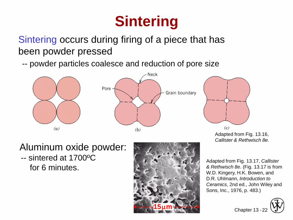
Sintering
Adapted from Fig. 13.16, Callister & Rethwisch 8e.
Aluminum oxide powder:-- sintered at 1700ºC
for 6 minutes.Adapted from Fig. 13.17, Callister & Rethwisch 8e. (Fig. 13.17 is from W.D. Kingery, H.K. Bowen, and D.R. Uhlmann, Introduction to Ceramics, 2nd ed., John Wiley and Sons, Inc., 1976, p. 483.)
15µm
Sintering occurs during firing of a piece that has been powder pressed-- powder particles coalesce and reduction of pore size

Chapter 13 -23
Tape Casting• Thin sheets of green ceramic cast as flexible tape• Used for integrated circuits and capacitors• Slip = suspended ceramic particles + organic liquid
(contains binders, plasticizers)
Fig. 13.18, Callister & Rethwisch 8e.

Chapter 13 -24
• Hardening of a paste – paste formed by mixing cement material with water
• Formation of rigid structures having varied and complex shapes
• Hardening process – hydration (complex chemical reactions involving water and cement particles)
Ceramic Fabrication Methods (iii)
GLASSFORMING
PARTICULATEFORMING
CEMENTATION
• Portland cement – production of:-- mix clay and lime-bearing minerals-- calcine (heat to 1400ºC)-- grind into fine powder
Chapter 13 -25
• Categories of ceramics: -- glasses -- clay products-- refractories -- cements-- advanced ceramics
• Ceramic Fabrication techniques:-- glass forming (pressing, blowing, fiber drawing).-- particulate forming (hydroplastic forming, slip casting,
powder pressing, tape casting)-- cementation
• Heat treating procedures-- glasses—annealing, tempering-- particulate formed pieces—drying, firing (sintering)
Summary

Chapter 14 - 1
ISSUES TO ADDRESS...• What are the general structural and chemical
characteristics of polymer molecules?• What are some of the common polymeric
materials, and how do they differ chemically?• How is the crystalline state in polymers different
from that in metals and ceramics ?
Chapter 14:Polymer Structures

Chapter 14 - 2
What is a Polymer?
Poly mermany repeat unit
Adapted from Fig. 14.2, Callister & Rethwisch 8e.
C C C C C CHHHHHH
HHHHHH
Polyethylene (PE)ClCl Cl
C C C C C CHHH
HHHHHH
Poly(vinyl chloride) (PVC)HH
HHH H
Polypropylene (PP)
C C C C C CCH3
HH
CH3CH3H
repeatunit
repeatunit
repeatunit
Chapter 14 - 3
Ancient Polymers• Originally natural polymers were used
– Wood – Rubber– Cotton – Wool– Leather – Silk
• Oldest known uses– Rubber balls used by Incas– Noah used pitch (a natural polymer)
for the ark

Chapter 14 - 4
Polymer CompositionMost polymers are hydrocarbons
– i.e., made up of H and C• Saturated hydrocarbons
– Each carbon singly bonded to four other atoms– Example:
• Ethane, C2H6
C C
H
H H H
HH

Chapter 14 - 5
Chapter 14 - 6
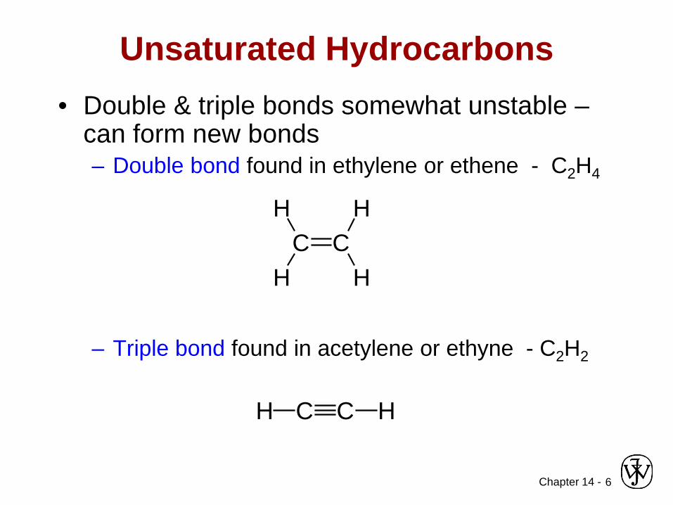
Unsaturated Hydrocarbons• Double & triple bonds somewhat unstable –
can form new bonds– Double bond found in ethylene or ethene - C2H4
– Triple bond found in acetylene or ethyne - C2H2
C CH
H
H
H
C C HH

Chapter 14 - 7
Isomerism• Isomerism
– two compounds with same chemical formula can have quite different structures
for example: C8H18• normal-octane
• 2,4-dimethylhexane
C C C C C C C CH
H
H
H
H
H
H
H
H
H
H
H
H
H
H
H
H
H H3C CH2 CH2 CH2 CH2 CH2 CH2 CH3=
H3C CH
CH3
CH2 CH
CH2
CH3
CH3
H3C CH2 CH3( )6
⇓
Chapter 14 - 8
Polymerization and Polymer Chemistry
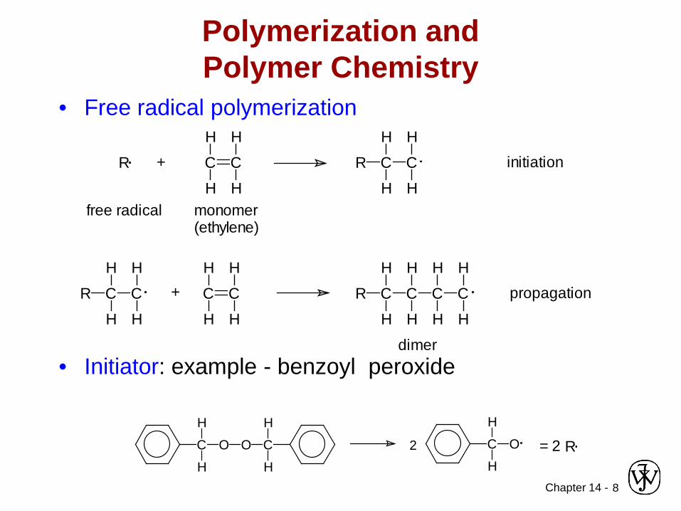
• Free radical polymerization
• Initiator: example - benzoyl peroxide
C
H
H
O O C
H
H
C
H
H
O2
C C
H H
HHmonomer(ethylene)
R +
free radical
R C C
H
H
H
H
initiation
R C C
H
H
H
H
C C
H H
HH
+ R C C
H
H
H
H
C C
H H
H H
propagation
dimer
R= 2

Chapter 14 - 9
Chemistry and Structure of Polyethylene
Adapted from Fig. 14.1, Callister & Rethwisch 8e.
Note: polyethylene is a long-chain hydrocarbon- paraffin wax for candles is short polyethylene

Chapter 14 -10
Bulk or Commodity Polymers
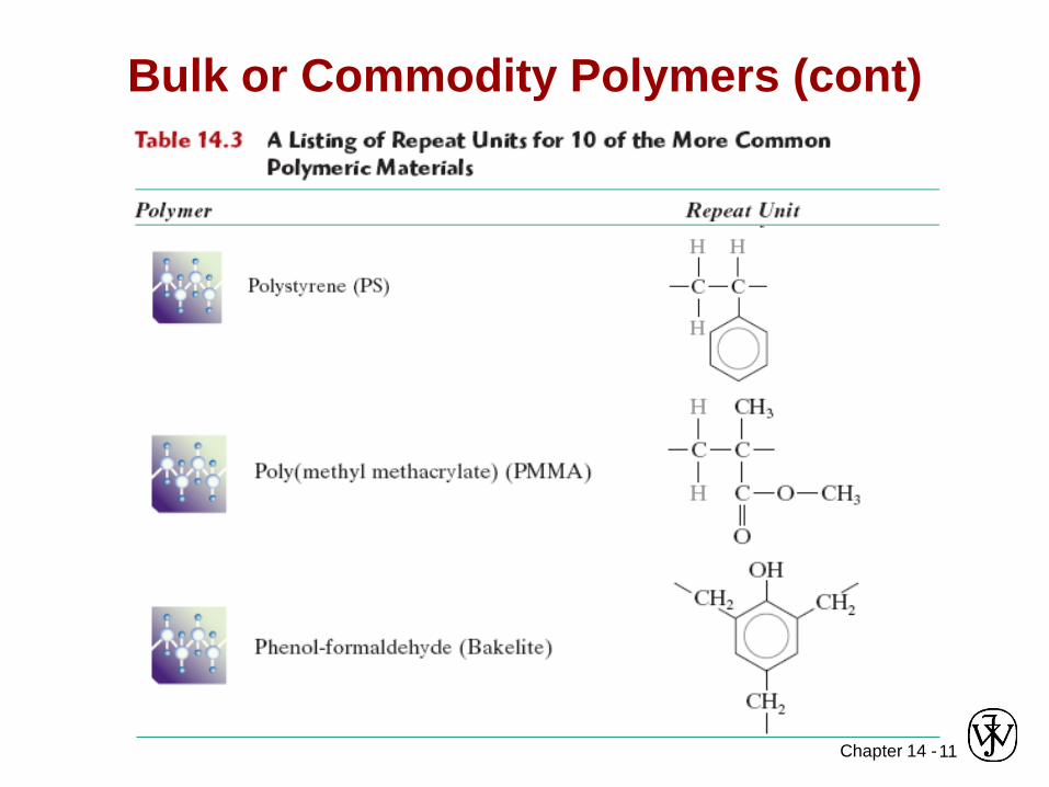
Chapter 14 -11
Bulk or Commodity Polymers (cont)
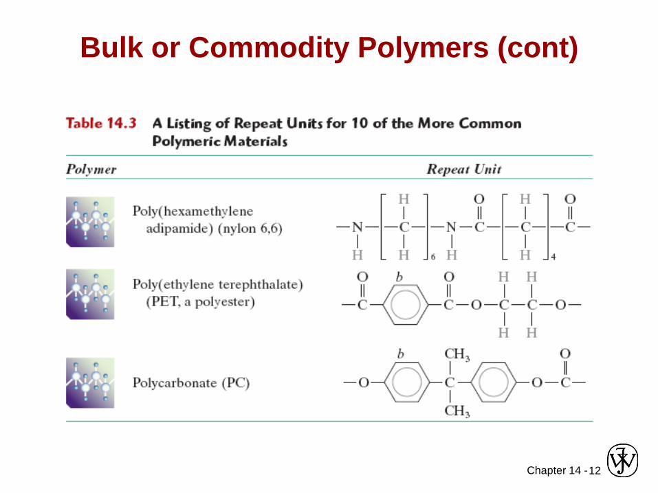
Chapter 14 -12
Bulk or Commodity Polymers (cont)
Chapter 14 -
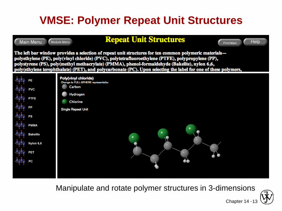
VMSE: Polymer Repeat Unit Structures
13
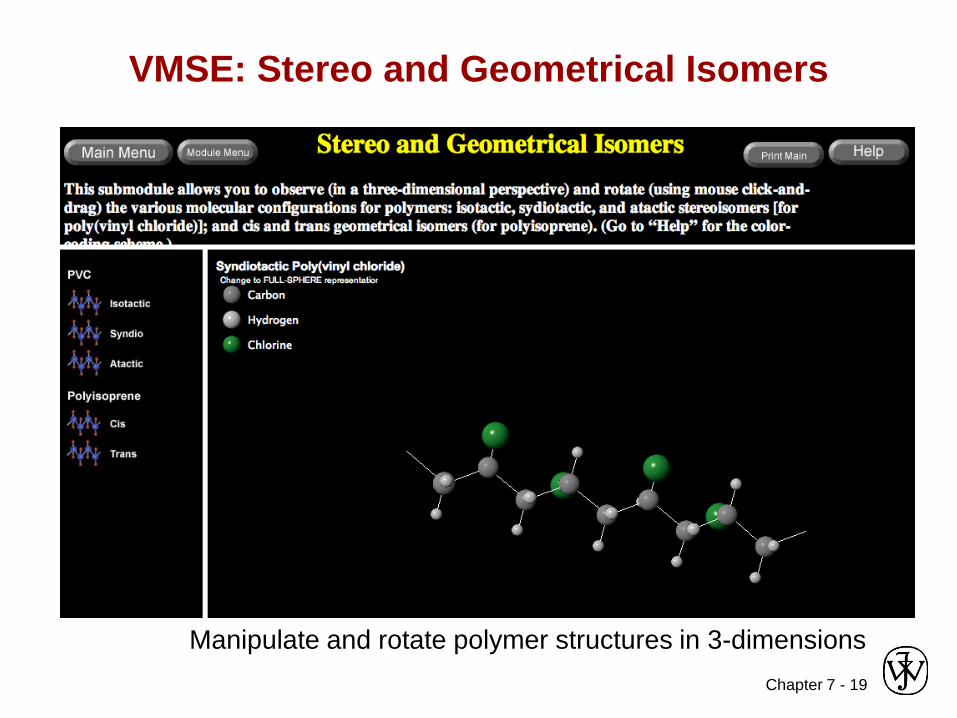
Manipulate and rotate polymer structures in 3-dimensions

Chapter 14 -14
MOLECULAR WEIGHT• Molecular weight, M: Mass of a mole of chains.
Low M
high M
Not all chains in a polymer are of the same length— i.e., there is a distribution of molecular weights
Chapter 14 -15
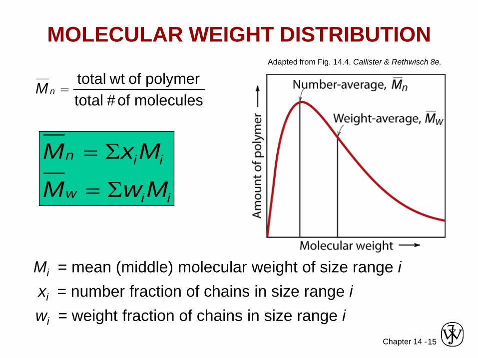
xi = number fraction of chains in size range i
molecules of #totalpolymer of wttotal
=nM
MOLECULAR WEIGHT DISTRIBUTION
Mn = ΣxiMi
Mw = ΣwiMi
Adapted from Fig. 14.4, Callister & Rethwisch 8e.
wi = weight fraction of chains in size range i
Mi = mean (middle) molecular weight of size range i
Chapter 14 -16
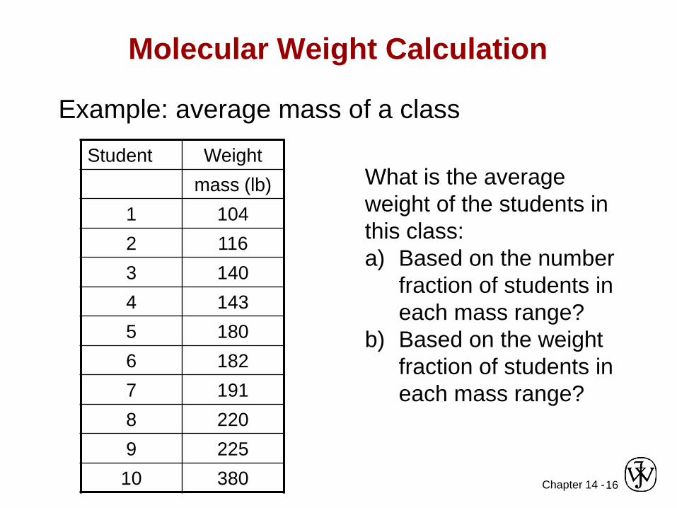
Molecular Weight Calculation
Example: average mass of a classStudent Weight
mass (lb)1 1042 1163 1404 1435 1806 1827 1918 2209 22510 380
What is the averageweight of the students inthis class:a) Based on the number
fraction of students in each mass range?
b) Based on the weight fraction of students in each mass range?
Chapter 14 -17
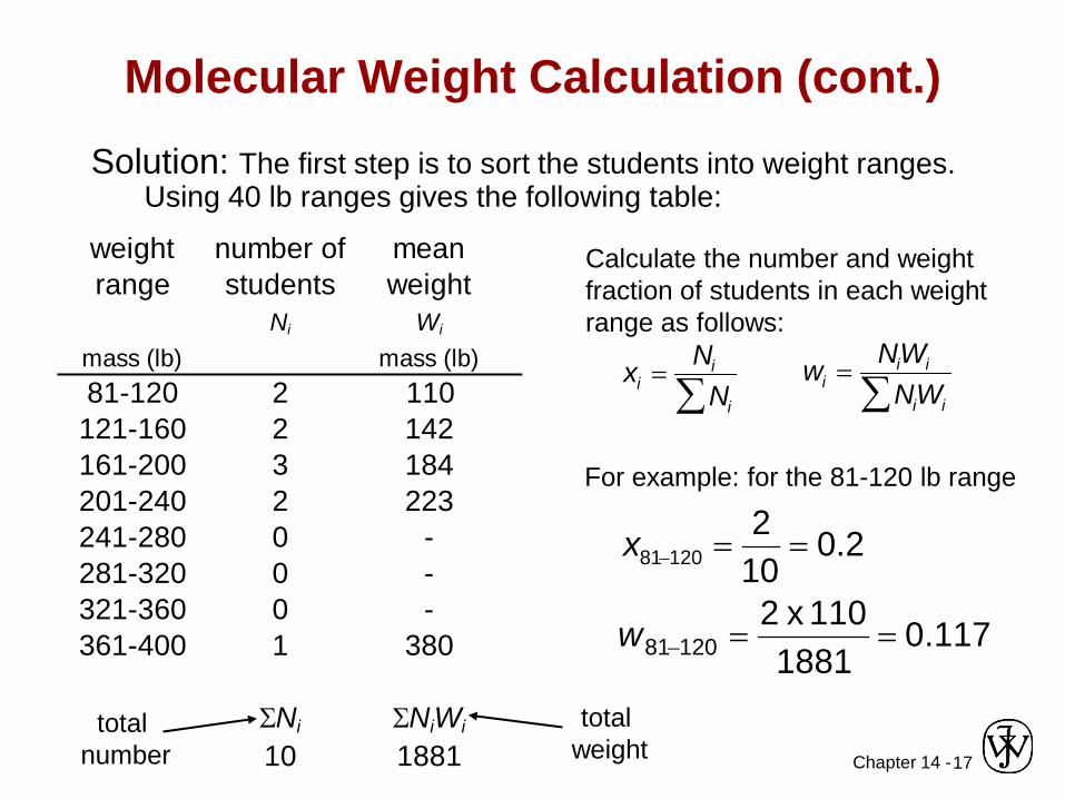
Molecular Weight Calculation (cont.)Solution: The first step is to sort the students into weight ranges.
Using 40 lb ranges gives the following table:
weight number of mean number weightrange students weight fraction fraction
Ni Wi xi wi
mass (lb) mass (lb)81-120 2 110 0.2 0.117
121-160 2 142 0.2 0.150161-200 3 184 0.3 0.294201-240 2 223 0.2 0.237241-280 0 - 0 0.000281-320 0 - 0 0.000321-360 0 - 0 0.000361-400 1 380 0.1 0.202
ΣNi ΣNiWi
10 1881total
numbertotal
weight
Calculate the number and weight fraction of students in each weight range as follows:
xi =Ni
Ni∑
wi =NiWi
NiWi∑
For example: for the 81-120 lb range
x81−120 =2
10= 0.2
117.01881
011 x 212081 ==−w

Chapter 14 -18
Molecular Weight Calculation (cont.)
Mn = xiMi∑ = (0.2 x 110 + 0.2 x 142 + 0.3 x 184 + 0.2 x 223 + 0.1 x 380) =188 lb
weight mean number weightrange weight fraction fraction
Wi xi wi
mass (lb) mass (lb)81-120 110 0.2 0.117
121-160 142 0.2 0.150161-200 184 0.3 0.294201-240 223 0.2 0.237241-280 - 0 0.000281-320 - 0 0.000321-360 - 0 0.000361-400 380 0.1 0.202
Mw = wiMi∑ = (0.117 x 110 + 0.150 x 142 + 0.294 x 184
+ 0.237 x 223 + 0.202 x 380) = 218 lb
Mw = wiMi∑ = 218 lb

Chapter 14 -19
Degree of Polymerization, DPDP = average number of repeat units per chain
iimfm
m
Σ=
=
:follows as calculated is this copolymers forunit repeat of weightmolecular average where
C C C C C C C CH
H
H
H
H
H
H
H
H
H
H
H
H
H
H
H
H
C C C C
H
H
H
H
H
H
H
H
H( ) DP = 6
mol. wt of repeat unit iChain fraction
mMDP n=

Chapter 14 -20
Adapted from Fig. 14.7, Callister & Rethwisch 8e.
Molecular Structures for Polymers
Branched Cross-Linked NetworkLinear
secondarybonding
Chapter 14 -21
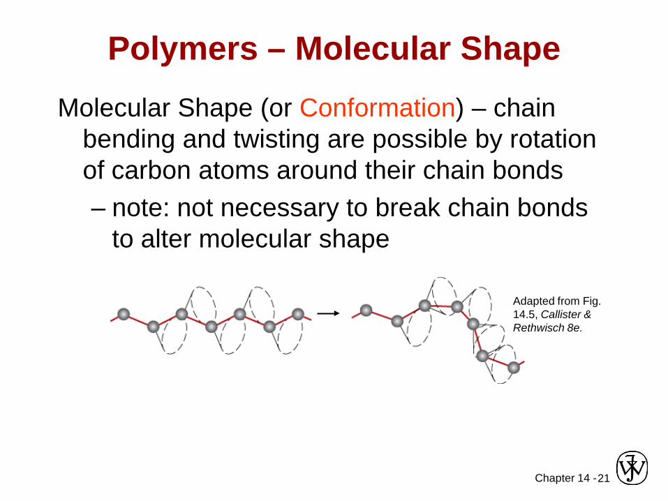
Polymers – Molecular ShapeMolecular Shape (or Conformation) – chain
bending and twisting are possible by rotation of carbon atoms around their chain bonds– note: not necessary to break chain bonds
to alter molecular shape
Adapted from Fig. 14.5, Callister & Rethwisch 8e.
Chapter 14 -22
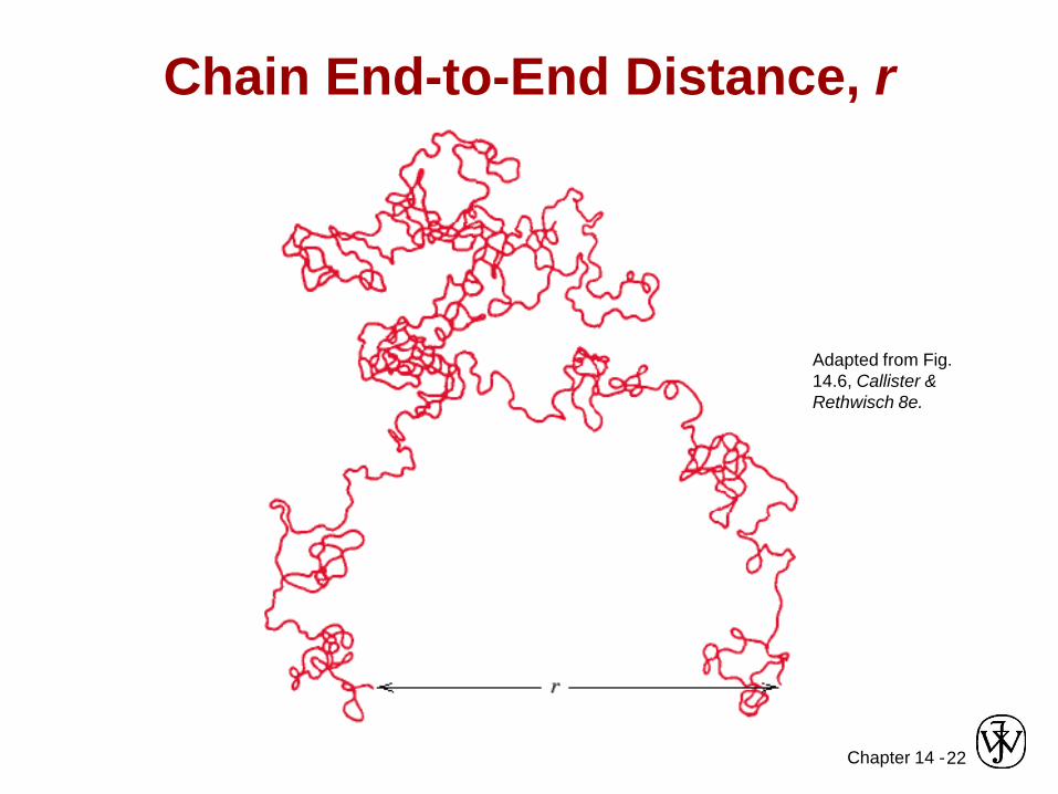
Chain End-to-End Distance, r
Adapted from Fig. 14.6, Callister & Rethwisch 8e.

Chapter 14 -23
Molecular Configurations for Polymers
Configurations – to change must break bonds• Stereoisomerism
EB
A
D
C C
D
A
BE
mirror plane
C CR
HH
HC C
H
H
H
R
or C C
H
H
H
R
Stereoisomers are mirrorimages – can’t superimposewithout breaking a bond
Chapter 14 -24
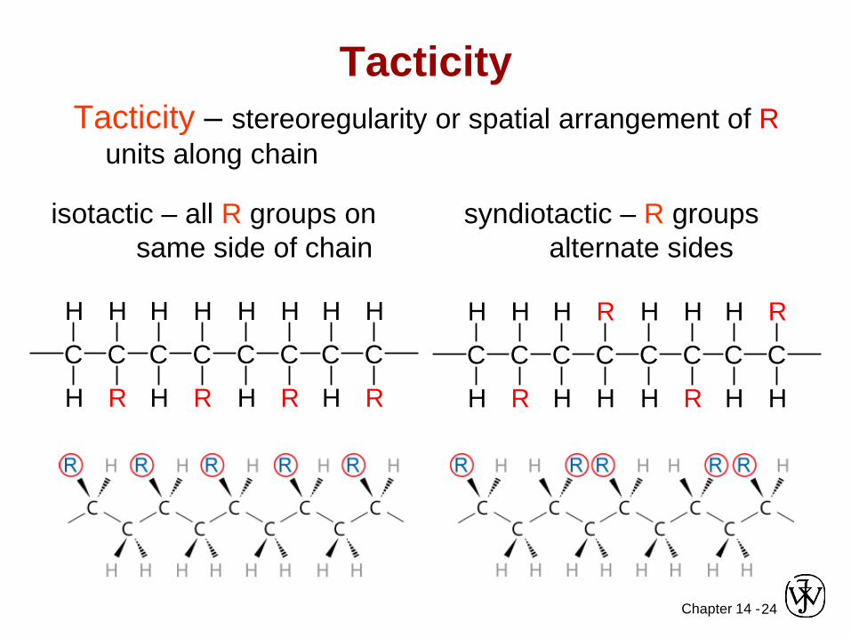
TacticityTacticity – stereoregularity or spatial arrangement of R
units along chain
C C
H
H
H
R R
H
H
H
CC
R
H
H
H
CC
R
H
H
H
CC
isotactic – all R groups on same side of chain
C C
H
H
H
R
C C
H
H
H
R
C C
H
H
H
R R
H
H
H
CC
syndiotactic – R groups alternate sides
Chapter 14 -25
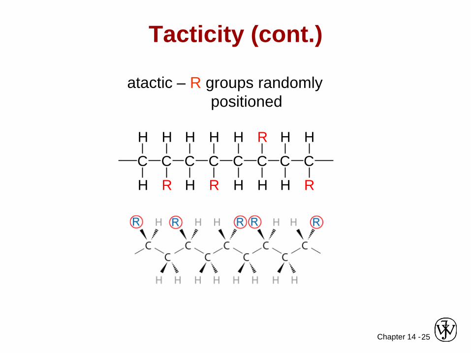
Tacticity (cont.)
atactic – R groups randomlypositioned
C C
H
H
H
R R
H
H
H
CC
R
H
H
H
CC
R
H
H
H
CC
Chapter 14 -26
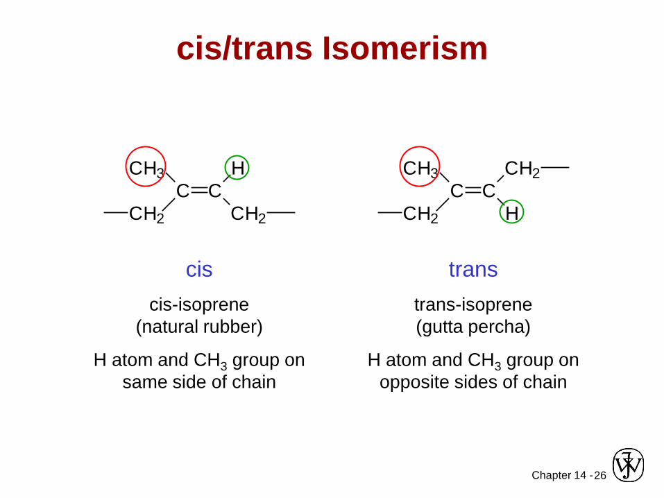
cis/trans Isomerism
C CHCH3
CH2 CH2
C CCH3
CH2
CH2
H
ciscis-isoprene
(natural rubber)
H atom and CH3 group on same side of chain
transtrans-isoprene (gutta percha)
H atom and CH3 group on opposite sides of chain
Chapter 14 -
VMSE: Stereo and Geometrical Isomers
27Chapter 7 - 19
Manipulate and rotate polymer structures in 3-dimensions
Chapter 14 -28
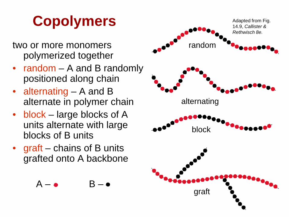
Copolymerstwo or more monomers
polymerized together • random – A and B randomly
positioned along chain• alternating – A and B
alternate in polymer chain• block – large blocks of A
units alternate with large blocks of B units
• graft – chains of B units grafted onto A backbone
A – B –
random
block
graft
Adapted from Fig. 14.9, Callister & Rethwisch 8e.
alternating

Chapter 14 -29
Crystallinity in Polymers• Ordered atomic
arrangements involving molecular chains
• Crystal structures in terms of unit cells
• Example shown– polyethylene unit cell
Adapted from Fig. 14.10, Callister & Rethwisch 8e.
Chapter 14 -30
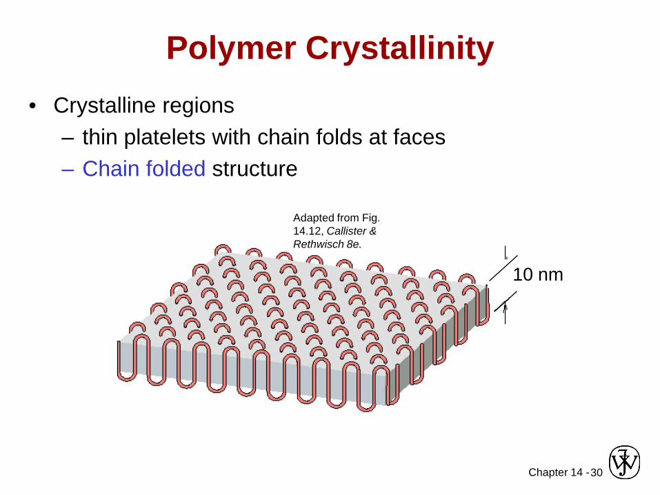
Polymer Crystallinity• Crystalline regions
– thin platelets with chain folds at faces– Chain folded structure
10 nm
Adapted from Fig. 14.12, Callister & Rethwisch 8e.

Chapter 14 -31
Polymer Crystallinity (cont.)Polymers rarely 100% crystalline• Difficult for all regions of all chains to
become aligned
• Degree of crystallinity expressed as % crystallinity.-- Some physical properties
depend on % crystallinity.-- Heat treating causes
crystalline regions to grow and % crystallinity to increase.
Adapted from Fig. 14.11, Callister 6e.(Fig. 14.11 is from H.W. Hayden, W.G. Moffatt,and J. Wulff, The Structure and Properties of Materials, Vol. III, Mechanical Behavior, John Wiley and Sons, Inc., 1965.)
crystalline region
amorphousregion

Chapter 14 -32
Polymer Single Crystals• Electron micrograph – multilayered single crystals
(chain-folded layers) of polyethylene• Single crystals – only for slow and carefully controlled
growth rates
Adapted from Fig. 14.11, Callister & Rethwisch 8e.
Chapter 14 -33
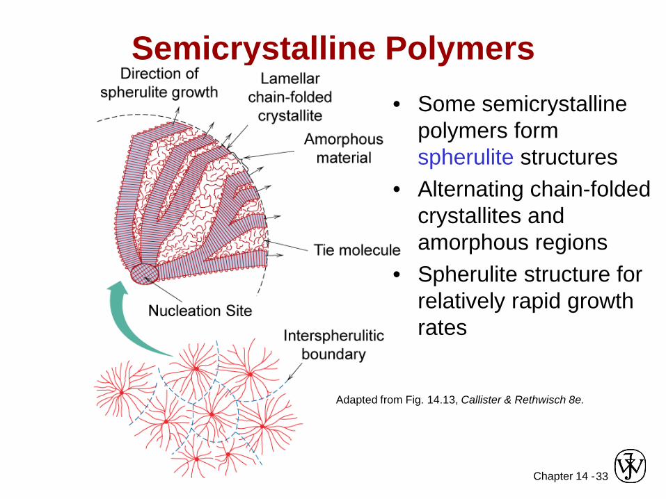
Semicrystalline Polymers
Spherulite surface
Adapted from Fig. 14.13, Callister & Rethwisch 8e.
• Some semicrystalline polymers form spherulite structures
• Alternating chain-folded crystallites and amorphous regions
• Spherulite structure for relatively rapid growth rates

Chapter 14 -34
Photomicrograph – Spherulites in Polyethylene
Adapted from Fig. 14.14, Callister & Rethwisch 8e.
Cross-polarized light used -- a maltese cross appears in each spherulite