Chapter 10 VAPOR AND COMBINED POWER...
14
Chapter 10 VAPOR AND COMBINED POWER CYCLES Copyright © The McGraw-Hill Companies, Inc. Permission required for reproduction or display. Thermodynamics: An Engineering Approach Seventh Edition Yunus A. Cengel, Michael A. Boles McGraw-Hill, 2011
Transcript of Chapter 10 VAPOR AND COMBINED POWER...
Chapter 10
VAPOR AND COMBINED POWER
CYCLES
Copyright © The McGraw-Hill Companies, Inc. Permission required for reproduction or display.
Thermodynamics: An Engineering Approach Seventh Edition
Yunus A. Cengel, Michael A. Boles
McGraw-Hill, 2011
2
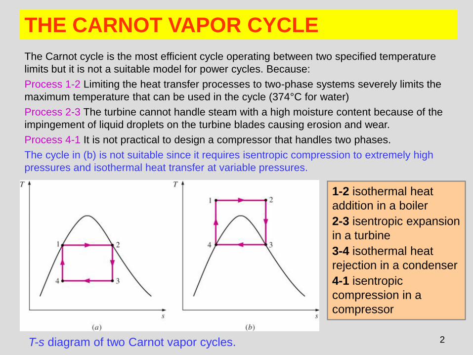
THE CARNOT VAPOR CYCLE
T-s diagram of two Carnot vapor cycles.
The Carnot cycle is the most efficient cycle operating between two specified temperature
limits but it is not a suitable model for power cycles. Because:
Process 1-2 Limiting the heat transfer processes to two-phase systems severely limits the
maximum temperature that can be used in the cycle (374°C for water)
Process 2-3 The turbine cannot handle steam with a high moisture content because of the
impingement of liquid droplets on the turbine blades causing erosion and wear.
Process 4-1 It is not practical to design a compressor that handles two phases.
The cycle in (b) is not suitable since it requires isentropic compression to extremely high
pressures and isothermal heat transfer at variable pressures.
1-2 isothermal heat
addition in a boiler
2-3 isentropic expansion
in a turbine
3-4 isothermal heat
rejection in a condenser
4-1 isentropic
compression in a
compressor
3
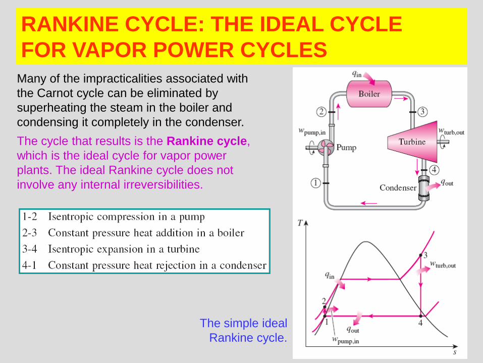
RANKINE CYCLE: THE IDEAL CYCLE
FOR VAPOR POWER CYCLES
Many of the impracticalities associated with
the Carnot cycle can be eliminated by
superheating the steam in the boiler and
condensing it completely in the condenser.
The cycle that results is the Rankine cycle,
which is the ideal cycle for vapor power
plants. The ideal Rankine cycle does not
involve any internal irreversibilities.
The simple ideal
Rankine cycle.
4
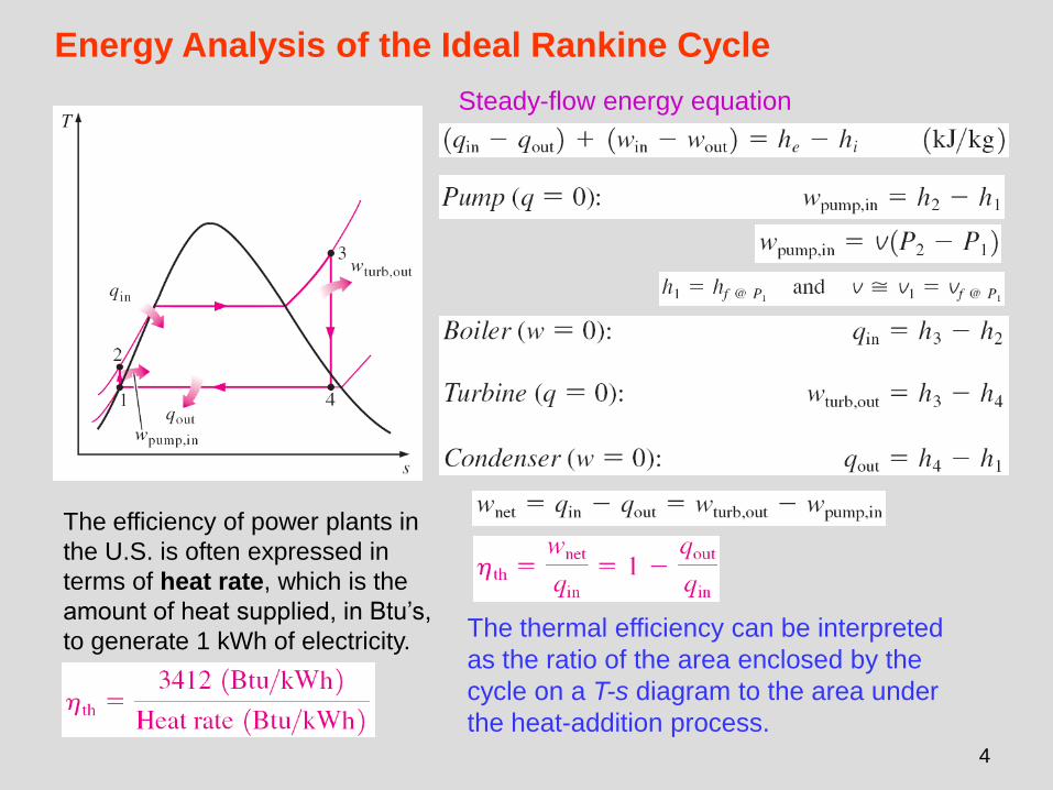
Energy Analysis of the Ideal Rankine Cycle
The efficiency of power plants in
the U.S. is often expressed in
terms of heat rate, which is the
amount of heat supplied, in Btu’s,
to generate 1 kWh of electricity. The thermal efficiency can be interpreted
as the ratio of the area enclosed by the
cycle on a T-s diagram to the area under
the heat-addition process.
Steady-flow energy equation
5
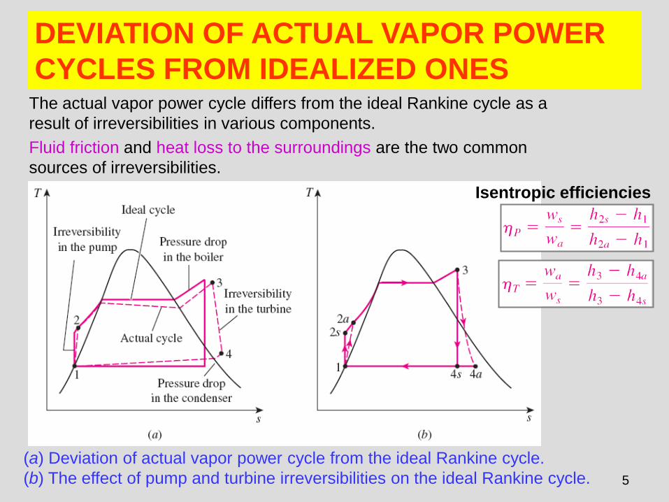
DEVIATION OF ACTUAL VAPOR POWER
CYCLES FROM IDEALIZED ONES
(a) Deviation of actual vapor power cycle from the ideal Rankine cycle.
(b) The effect of pump and turbine irreversibilities on the ideal Rankine cycle.
The actual vapor power cycle differs from the ideal Rankine cycle as a
result of irreversibilities in various components.
Fluid friction and heat loss to the surroundings are the two common
sources of irreversibilities.
Isentropic efficiencies
6
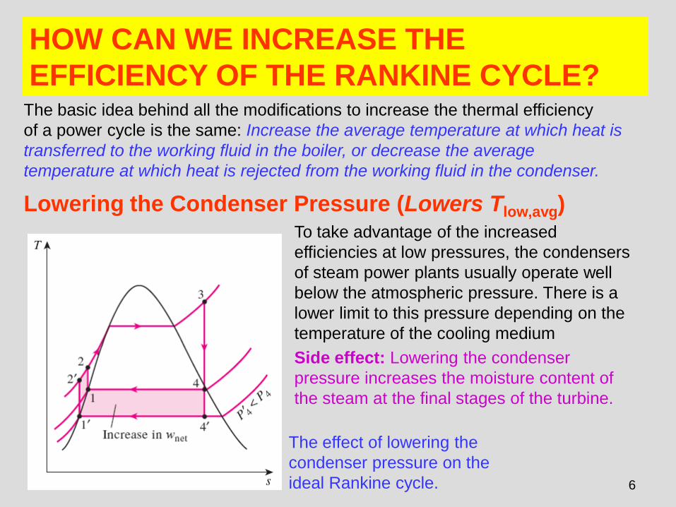
HOW CAN WE INCREASE THE
EFFICIENCY OF THE RANKINE CYCLE?
The effect of lowering the
condenser pressure on the
ideal Rankine cycle.
The basic idea behind all the modifications to increase the thermal efficiency
of a power cycle is the same: Increase the average temperature at which heat is
transferred to the working fluid in the boiler, or decrease the average
temperature at which heat is rejected from the working fluid in the condenser.
Lowering the Condenser Pressure (Lowers Tlow,avg) To take advantage of the increased
efficiencies at low pressures, the condensers
of steam power plants usually operate well
below the atmospheric pressure. There is a
lower limit to this pressure depending on the
temperature of the cooling medium
Side effect: Lowering the condenser
pressure increases the moisture content of
the steam at the final stages of the turbine.
7
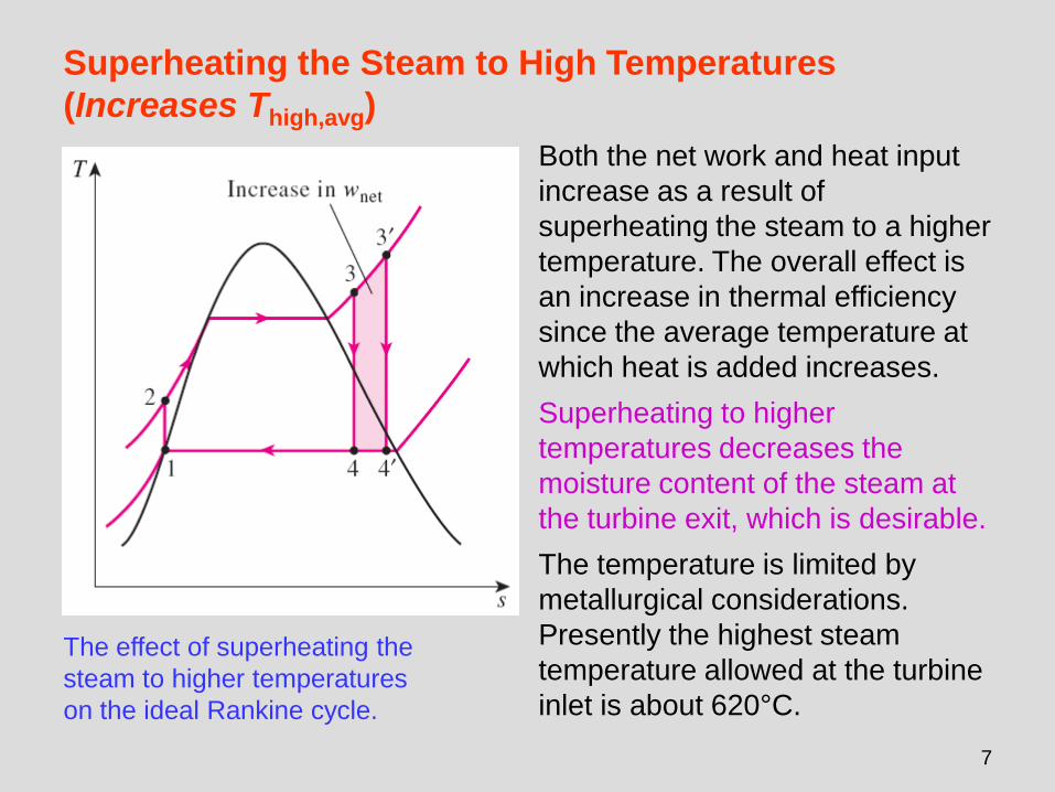
The effect of superheating the
steam to higher temperatures
on the ideal Rankine cycle.
Superheating the Steam to High Temperatures
(Increases Thigh,avg)
Both the net work and heat input
increase as a result of
superheating the steam to a higher
temperature. The overall effect is
an increase in thermal efficiency
since the average temperature at
which heat is added increases.
Superheating to higher
temperatures decreases the
moisture content of the steam at
the turbine exit, which is desirable.
The temperature is limited by
metallurgical considerations.
Presently the highest steam
temperature allowed at the turbine
inlet is about 620°C.
8
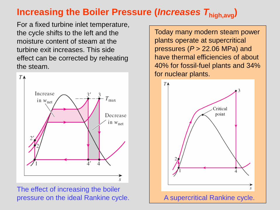
Increasing the Boiler Pressure (Increases Thigh,avg)
The effect of increasing the boiler
pressure on the ideal Rankine cycle.
For a fixed turbine inlet temperature,
the cycle shifts to the left and the
moisture content of steam at the
turbine exit increases. This side
effect can be corrected by reheating
the steam.
A supercritical Rankine cycle.
Today many modern steam power
plants operate at supercritical
pressures (P > 22.06 MPa) and
have thermal efficiencies of about
40% for fossil-fuel plants and 34%
for nuclear plants.
9
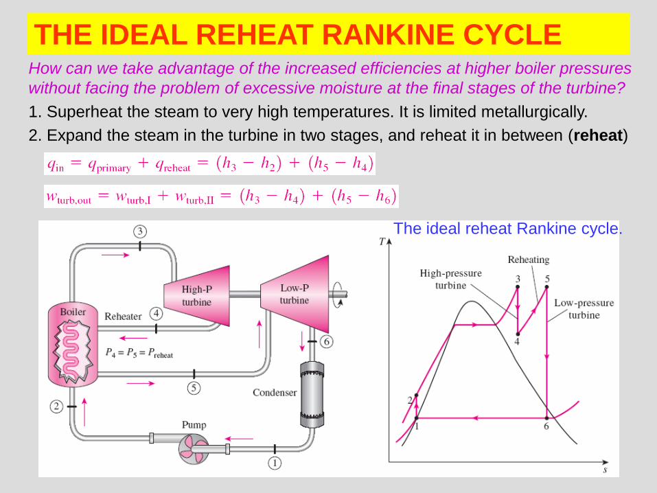
THE IDEAL REHEAT RANKINE CYCLE How can we take advantage of the increased efficiencies at higher boiler pressures
without facing the problem of excessive moisture at the final stages of the turbine?
1. Superheat the steam to very high temperatures. It is limited metallurgically.
2. Expand the steam in the turbine in two stages, and reheat it in between (reheat)
The ideal reheat Rankine cycle.
10
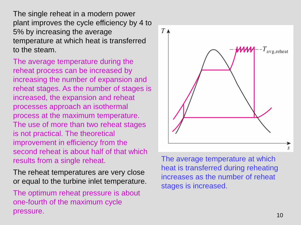
The average temperature at which
heat is transferred during reheating
increases as the number of reheat
stages is increased.
The single reheat in a modern power
plant improves the cycle efficiency by 4 to
5% by increasing the average
temperature at which heat is transferred
to the steam.
The average temperature during the
reheat process can be increased by
increasing the number of expansion and
reheat stages. As the number of stages is
increased, the expansion and reheat
processes approach an isothermal
process at the maximum temperature.
The use of more than two reheat stages
is not practical. The theoretical
improvement in efficiency from the
second reheat is about half of that which
results from a single reheat.
The reheat temperatures are very close
or equal to the turbine inlet temperature.
The optimum reheat pressure is about
one-fourth of the maximum cycle
pressure.
11
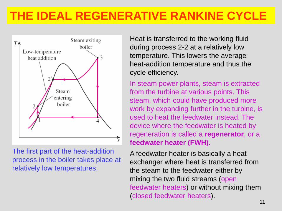
THE IDEAL REGENERATIVE RANKINE CYCLE
The first part of the heat-addition
process in the boiler takes place at
relatively low temperatures.
Heat is transferred to the working fluid
during process 2-2 at a relatively low
temperature. This lowers the average
heat-addition temperature and thus the
cycle efficiency.
In steam power plants, steam is extracted
from the turbine at various points. This
steam, which could have produced more
work by expanding further in the turbine, is
used to heat the feedwater instead. The
device where the feedwater is heated by
regeneration is called a regenerator, or a
feedwater heater (FWH).
A feedwater heater is basically a heat
exchanger where heat is transferred from
the steam to the feedwater either by
mixing the two fluid streams (open
feedwater heaters) or without mixing them
(closed feedwater heaters).
12
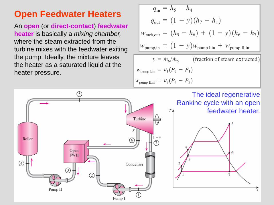
Open Feedwater Heaters
An open (or direct-contact) feedwater
heater is basically a mixing chamber,
where the steam extracted from the
turbine mixes with the feedwater exiting
the pump. Ideally, the mixture leaves
the heater as a saturated liquid at the
heater pressure.
The ideal regenerative
Rankine cycle with an open
feedwater heater.
13
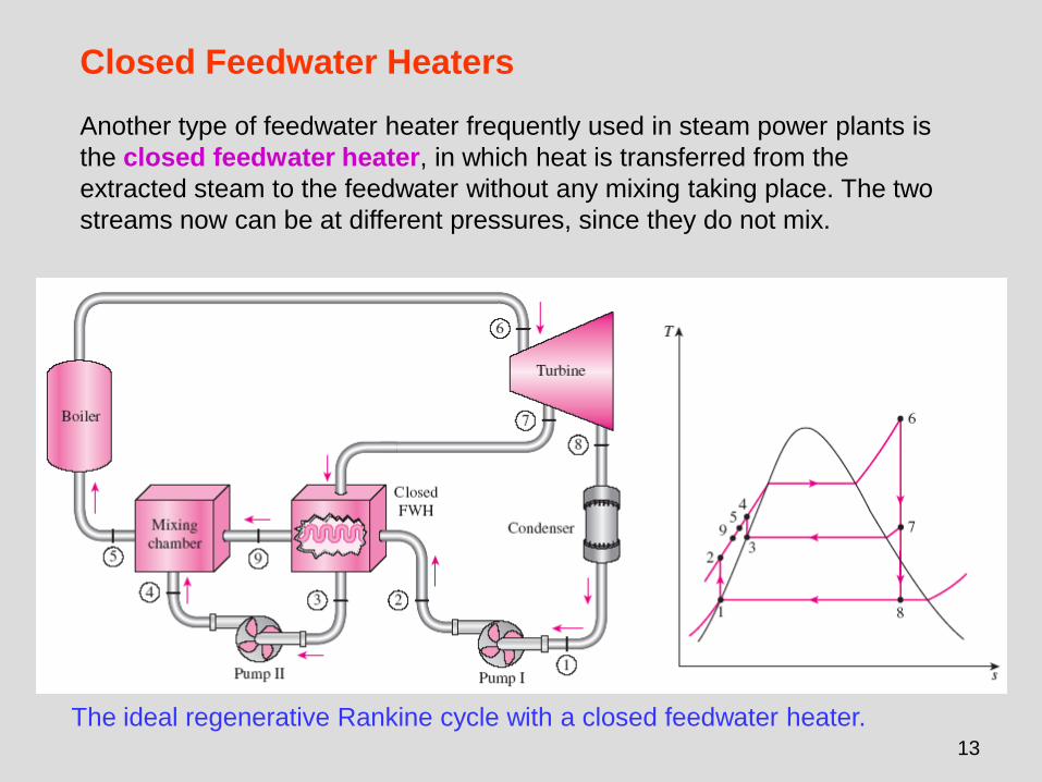
Closed Feedwater Heaters
The ideal regenerative Rankine cycle with a closed feedwater heater.
Another type of feedwater heater frequently used in steam power plants is
the closed feedwater heater, in which heat is transferred from the
extracted steam to the feedwater without any mixing taking place. The two
streams now can be at different pressures, since they do not mix.
14
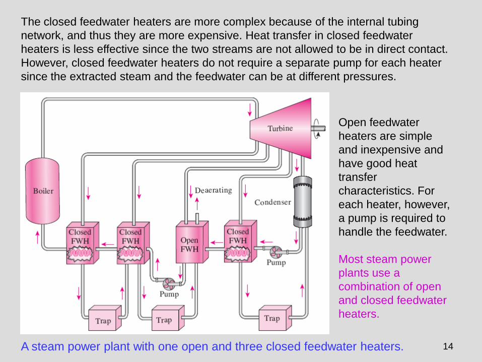
The closed feedwater heaters are more complex because of the internal tubing
network, and thus they are more expensive. Heat transfer in closed feedwater
heaters is less effective since the two streams are not allowed to be in direct contact.
However, closed feedwater heaters do not require a separate pump for each heater
since the extracted steam and the feedwater can be at different pressures.
Open feedwater
heaters are simple
and inexpensive and
have good heat
transfer
characteristics. For
each heater, however,
a pump is required to
handle the feedwater.
Most steam power
plants use a
combination of open
and closed feedwater
heaters.
A steam power plant with one open and three closed feedwater heaters.