Igniting Self-Directed Learning and Higher Level Workforce ...
MSIS 27/CH 10/Rev 1017/Page 1 of 46
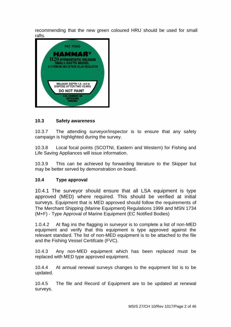
Chapter 10 – LIFE SAVING APPLIANCES 10.1 General These instructions do not give information on the number and type of Life Saving Appliances (LSA) that is required by each fishing vessel. The attending surveyor will have to view the individual regulations covering size and area of operation of the fishing vessel involved. 10.2 Compatibility 10.2.1 The surveyor should ensure that all LSA is compatible. This can be shown by demonstration where information from manufacturers or previous survey is not available. 10.2.2 Examples are - lifejackets and immersion suits should be capable of being worn together, when required, and a normal evacuation carried out. If the immersion suit is not required to be carried the surveyor should consider whether safety would be enhanced by its carriage? If it is not compatible with the required lifejacket an advisory word of caution may be more appropriate than a deficiency. 10.2.3 Lifejackets lights should be automatic wherever possible. Approved manual lights are acceptable but the surveyor should point out the issues of manual activation in cold waters or the issues with an unconscious casualty. They should be secured as high as possible to be visible when a casualty is floating normally in the water. 10.2.4 Lifejackets are encouraged to be worn at all times on deck. Working lifejackets may be carried in addition to the statutory requirements but should not be included in the certification process. 10.2.5 Hydrostatic release unit should be acceptable for the size and type of liferaft. It is apparent that a number of smaller vessels covered by MCA certification are likely to be carrying life rafts which are smaller than those carried on board vessels which are subject to SOLAS requirements. 10.2.6 There may be some doubt as to whether or not the hydrostatic release units supplied for SOLAS size life rafts are appropriate for life rafts of below SOLAS size. 10.2.7 In cases where smaller than SOLAS size life rafts are fitted, and there is any doubt with respect to the compatibility of HRU and the raft itself, then confirmation is to be sought from manufacturers and/or equipment suppliers that the breaking strength of the weak link and the size of the raft are compatible. 10.2.8 Hammar have also produced a small green cartridge type weak link which is for attaching to the standard Hammar HRU. They are now
MSIS 27/CH 10/Rev 1017/Page 2 of 46
recommending that the new green coloured HRU should be used for small rafts.
10.3 Safety awareness 10.3.7 The attending surveyor/inspector is to ensure that any safety campaign is highlighted during the survey. 10.3.8 Local focal points (SCOTNI, Eastern and Western) for Fishing and Life Saving Appliances will issue information. 10.3.9 This can be achieved by forwarding literature to the Skipper but may be better served by demonstration on board. 10.4 Type approval
10.4.1 The surveyor should ensure that all LSA equipment is type approved (MED) where required. This should be verified at initial surveys. Equipment that is MED approved should follow the requirements of
The Merchant Shipping (Marine Equipment) Regulations 1999 and MSN 1734 (M+F) - Type Approval of Marine Equipment (EC Notified Bodies) 1.0.4.2 At flag ins the flagging in surveyor is to complete a list of non-MED equipment and verify that this equipment is type approved against the relevant standard. The list of non-MED equipment is to be attached to the file and the Fishing Vessel Certifcate (FVC). 10.4.3 Any non-MED equipment which has been replaced must be replaced with MED type approved equipment. 10.4.4 At annual renewal surveys changes to the equipment list is to be updated. 10.4.5 The file and Record of Equipment are to be updated at renewal surveys.
MSIS 27/CH 10/Rev 1017/Page 3 of 46
10.5 Ready availability 10.5.1 It is essential the surveyor ensures that all safety equipment is ready for immediate use. This includes equipment on board which is not required by legislation. 10.5.2 Any life saving equipment found on board should be fit for purpose and ready for use. 10.5.3 The attending surveyor should always record this as a deficiency, even if the deficiency is rectified before the survey/inspection is completed. These records are vital to show if any programme is having a measurable outcome. 10.5.4 Inspection of the life-saving appliances, including lifeboat equipment, must be carried out monthly using a checklist to ensure that they are complete and in good order. A report of the inspection shall be entered in the logbook. 10.8 Servicing of LSA equipment 10.8.1 Depending on the type of inspection/survey being carried out the following equipment should be verified as having been serviced by an approved service provider:
Lifeboat davits (flag in, initial, annual and renewal survey); Lifeboat release gear (flag in, initial, annual);
Rescue boat davit and release hook (flag in, initial , annual and
renewal survey); Inflatable rescue boat (flag in, initial , annual and renewal survey);
Solid rescue boat (flag in, initial and renewal );
Liferaft davit (flag in, initial, annual and renewal survey);
Davit launched liferaft release hook (flag in, initial, annual and
renewal survey);
Inflatable liferaft (flag in, initial, annual and renewal survey);
Hydrostatic release units for life rafts and EPIRB (flag in, initial, annual and renewal survey);
EPIRB (flag in, initial, annual and renewal survey);
Inflatable lifejackets (flag in, initial, annual and renewal survey);
MSIS 27/CH 10/Rev 1017/Page 4 of 46
Immersion suits (flag in and as per manufacturers instructions). 10.9 Fishing vessels and other UK Ship Classes 10.9.1 It should be noted that some fishing vessels may have dual certification. An example may be a Small Commercial Vessel Certificate in addition to the Fishing Vessel Certificate or a Class VI passenger and Fishing vessel certificate. 10.9.2 The requirements for LSA are known to have different issues. For example just because an under 15m meets the requirements of a fishing vessel it does not necessarily mean that meets the requirements of a code vessel. 10.9.3 The surveyor/inspector should ensure he is aware of what legislation or code he/she is applying before commencing the work. 10.10 Exemptions/Exceptions 10.10.1 There are some over 24m metre vessels which have exemptions from the carriage of rescue boats. 10.10.2 Exemptions from the requirement for vessels to carry an “inflatable boat” should only be considered for “existing vessels” 10.10.3 Surveyors may consider issuing exemptions for either of the following reasons and conditions:
• Due to the limited numbers of crew onboard a parent vessel it may not be possible to ensure safe and proper operation of an inflatable boat. An inflatable boat (this being the type of craft most commonly fitted) should normally have a crew of at least at least two persons. This should not result in too great a reduction in crew numbers remaining on board the parent vessel, especially during an envisaged retrieval of the vessel’s own crew from the water. As a guide, to enable the safe operation of an inflatable boat, the total complement of crew on the parent vessel should be no less than six (under normal fishing conditions and including the skipper); or
• Due to limited available stowage and/or launch positions. Under certain fishing methods with the gear deployed, the only available stowage would place an inflatable boat and its occupants in danger of being caught in the vessel’s gear and/or propeller.
10.11 Lifejackets 10.11.1 General 10.11.1.1 No lifejacket should be passed as part of the statutory equipment of a ship unless it:-
MSIS 27/CH 10/Rev 1017/Page 5 of 46
• is of an accepted type;
• complies in all respects with the accepted specification;
• is in good condition and fit for the service intended. On board repairs or modifications are not acceptable.
10.11.1.2 Any lifejacket supplied new should be MED approved with required wheelmark and Type approval certification. 10.11.1.3 They can be solid-filled type or comply with BS EN 396 or BSEN 399, which will eventually be replaced by EN ISO 12402, with automatic gas inflation and at least 150 Newtons of buoyancy. It should be fitted with retro-reflective tape, a type approved light and a whistle. 10.11.1.4 Inflatable lifejackets are required to be serviced annually at an approved service station. 10.11.1.5 Lifejackets must be be stowed either in a deckhouse or other dry and readily accessible position; and have stowage positions clearly and permanently marked (it is strongly recommended that lifejackets are always worn when working on deck). 10.11.2 Donning instructions Lifejacket manufacturers should provide illustrated directions for donning and adjustment. This should be displayed and held with vessels training information (where required) 10.12 Lifebuoys 10.12.1 General 10.12.1.1 Lifebuoys should be marked with the vessel name and port of registry or fishing number with reflective tape. They may be circular or horseshoe in shape on under 15m fishing vessels. 10.12.1.2 Lifebuoys made of synthetic materials should be embossed with the manufacturer's trade mark, or trade name of the lifebuoy. 10.12.1.3 Lifebuoys should be of a standard international orange colour or if an old cork lifebuoy covered with a canvas material - painted red and white. 10.12.1.4 Any lifebuoy supplied new should be MED approved with required wheelmark and Type approval certification.
MSIS 27/CH 10/Rev 1017/Page 6 of 46
10.12.2 Lifebuoy self-igniting lights 10.12.2.1 Lights of this type must be self-igniting in water, and be capable of burning brightly for at least 2 hours. The lights should be stowed to prevent accidental or premature ignition. They may be operated by water activated cells or dry batteries. The line should be attached to the light at the level of the centre of flotation where possible to prevent inclination of the signal in a seaway. 10.12.3 Lifebuoy self-activating smoke signals These are usually combined with the man overboard lights for bridge wing lifebuoys. They should be secured as per manufacturers instructions. It is essential that the markers are connected with the lifebuoy with a suitable length of line which will activate the smoke signal when the buoy is released. 10.12.4 Lifebuoy buoyant lifelines 10.12.4.1 Surveyors should note that the property of grip is essential in this application and should ensure that a suitable type of rope is used. They should be of a suitable length, not less than twice the height at which it is stowed above the waterline in the lightest seagoing condition, or 30 metres, whichever is greater. For handling characteristics and its ability to float 8mm polypropylene should be used. Such lifebuoys should not have self-igniting lights. 10.12.4.2 A buoyant quoit fitted with 18m of floating line can be fitted in place of one of the required lifebuoys. 10.12.5 Stowage of lifebuoys 10.12.5.1 At least two of the lifebuoys provided with self-igniting lights in accordance with paragraph 10.12.2 must be provided with self-activating smoke signals and shall, where practicable, be capable of quick release from the navigating bridge. 10.12.5.2 Where four or more lifebuoys are required by the Regulations, two of them should be carried in brackets or cleats attached to the deck rails or some other convenient place near the stern of the ship. The remainder, if any, should be carried in a similar manner, well distributed on the weather deck rails. In small ships where there is difficulty in arranging for the quick release of lifebuoys from the navigating bridge, the surveyor may waive this requirement at his discretion if he is satisfied that the best alternative arrangement is made to ensure that the lifebuoys are readily available. 10.12.5.3 Lifebuoys should not be permanently secured in any way. 10.12.5.4 At least half of the number of lifebuoys must be provided with self-igniting lights.

MSIS 27/CH 10/Rev 1017/Page 7 of 46
10.12.5.5 At least one lifebuoy on each side of the vessel shall be fitted with a buoyant lifeline equal in length to not less than twice the height at which it is stowed above the waterline in the lightest seagoing condition, or 30 metres, whichever is greater. Such lifebuoys should not have self-igniting lights. 10.13 Pyrotechnics 10.13.1 General 10.13.1.1 Every vessel must be provided with means of making effective distress signals by day and by night. All pyrotechnic distress signals shall be packaged in a watertight container and shall be clearly and indelibly labelled to indicate their purpose. 10.13.1.2 Distress signals must be of an approved type. They shall be so placed as to be readily accessible and their position must be plainly indicated. 10.13.1.3 Pyrotechnic signals should be inspected regularly and replaced if any doubt exists as to their condition. In any case, all pyrotechnics should be renewed within four years from the date of manufacture. Pyrotechnics in liferafts may be retained if their expiry date is 6 months or more after the liferaft servicing date provided they appear to be in good condition. 10.13.1.4 Parachute flares -supplied new should be MED approved with required wheelmark and Type approval certification. 10.13.1.5 Hand held flares- supplied new should be MED approved with required wheelmark and Type approval certification. 10.13.1.6 Buoyant smoke signals - supplied new should be MED approved with required wheelmark and Type approval certification. 10.13.1.7 Line throwing apparatus- supplied new should be MED approved with required wheelmark and Type approval certification. 10.13.2 Disposal Disposal of any out of date LSA equipment should be carried out in a responsible manner in line with current legislation and guidance. 10.14 Immersion suits 10.14.1 General No immersion suit or anti-exposure suit should be passed as part of the statutory equipment of a ship unless it:
• is of an approved type and marked as such;
• complies in all respects with the accepted specifications;
MSIS 27/CH 10/Rev 1017/Page 8 of 46
• is in good condition and fit for the service intended; and
• there is a size suitable for each person on board. 10.14.2 Donning instructions 10.14.2.1 Manufacturers should ensure that illustrated instructions for donning, adjustment and maintenance of immersion suits or anti-exposure suits are supplied with each suit. 10.14.2.2 Instructions suitably protected from damage should be available for display and for inclusion into training and maintenance manuals , if carried. Consideration should be given to where there is adequate space for donning the suit. 10.14.3 Repair and servicing of immersion suits 10.14.3.1 Repairs and servicing of immersion suits should only be carried out by the manufacturers or their authorised agents. This does not include carrying out work such as replacing independent light or lubricating a zip. 10.14.3.2 Servicing would be required if the surveyor is in doubt over the watertight integrity of seams etc. or the obvious degradation to the material 10.14.4 Stowage of immersion suits The stowage position of immersion suits must be in a place where they are readily available for collection by crews. Care should be taken to ensure that conditions in the stowage position chosen will not adversely affect the immersion suit. 10.15 Thermal protective aids 10.15.1 General
No thermal protective aid should be passed as part of statutory equipment of a ship unless it:
• is of an approved type;
• complies in all respects with the accepted specifications; and
• is in good condition and fit for the service intended.
MSIS 27/CH 10/Rev 1017/Page 9 of 46
10.15.2 Donning Instructions
10.15.2.1 Manufacturers should provide illustrated instructions for donning and discarding thermal protective aids with each aid. 10.15.2.2 Instructions, suitably protected from damage, should be available for display and for inclusion into training and maintenance manuals, if required. 10.16 VHF radio (portable) 10.16.1 General 10.16.1.1 Radio equipment forming part of a ship's live-saving appliances will perform one or more functional requirements when used in a survival craft thereby enhancing the success of any Search and Rescue (SAR) operations. These include;
• transmit to-shore distress alerts;
• transmit and receive on-scene communications; and
• transmitting signals for locating.
10.16.1.2 The two-way (VHF) Radiotelephone apparatus should be portable. The equipment should be capable of being used for on-scene communication between survival craft, between survival craft and ship and between survival craft and rescue unit. It may also be used for on-board communications when capable of operating on appropriate frequencies. 10.16.1.3 The equipment should be MED wheelmarked and have a type approval certificate or should conform with one of the following performance standards adopted by the IMO through Resolution:
• if installed on or after 23 November 1996, Assembly Resolution A.809(19); or
• if installed before 23 November 1996, Assembly Resolution A.762(18).
10.16.1.4 Equipment provided prior to 1 February 1992 is not required to comply with a IMO performance standard providing suitable arrangements have been made to render the equipment watertight and that it is capable of using the VHF frequencies required by the IMO standards Brief, clear, operating instructions should be provided on the equipment (or adjacent to it in the case of fixed installations). 10.16.1.4 That equipment to be used for Life-Saving purposes should be clearly identified as such through being either of a highly visible yellow/orange colour or marked with a surrounding yellow/orange marking strip.
MSIS 27/CH 10/Rev 1017/Page 10 of 46
10.16.2 Power supply 10.16.2.1 The source of energy should have a capacity to ensure at least 8 hour, preferably 24 hour operation at the highest rated power of the equipment with a duty cycle of 1:9. This duty cycle is defined as 6 seconds transmission, 6 seconds reception above squelch opening level and 48 seconds below squelch opening level. The source of energy should comply with the following:
• A sealed primary battery which should be:
• of a type which will not emit substances which may be injurious to personnel, or damaging to the equipment or fabric of the survival craft. This requirement should be met whether the power source is in a stored condition or normal use;
• securely mounted and clearly marked with the shelf life whose expiry should not be less than 2 years from the date of survey; and
• the battery should have sufficient capacity so that routine testing of 2 minutes once per week should not reduce its capacity below that needed to conform to the operational requirements recommended above. Where the battery is used to supply power to any other equipment, sufficient capacity should be available to operate this equipment at its maximum rated power for the period recommended in addition to the radio apparatus.
10.16.2.2 Batteries should be disposed of strictly in accordance with manufacturer’s instructions. 10.17 Radar transponders (SARTS) 10.17.1 General 10.17.1.1 The equipment should be kept on either side of the ship in a suitable place ready to be moved into a survival craft in case of emergency; where only one is required, it should be located at a suitable location for moving into the survival craft. In ships where the disposition of superstructures or deck houses is such as to involve substantial fore and aft separation and, where two transponders are carried, they should not be located in the same area of superstructure or in the same deck house.. 10.17.1.2 The equipment should be clearly marked with the manufacturer's identity, type or model identification, serial number, brief operating instructions and the expiry date for the primary batteries used. The minimum safe distance from the standard or magnetic steering compass at which the equipment may be installed should also be marked. The arrangements made in individual ships and/or survival craft should be determined to the satisfaction of the
MSIS 27/CH 10/Rev 1017/Page 11 of 46
marine surveyor in consultation with the radio surveyor who should inspect the equipment as part of each survey of Life-Saving Appliances. 10.17.2 Securing the equipment in liferafts 10.17.2.1 Every transponder should be provided with fittings suitable for mounting in each liferaft at a height of not less than 1 metre above the water line. These fittings should be attached to, or located adjacent to, the radar transponder at all times. Clear instructions on how to use the fittings in an emergency should be marked on the radar transponder or provided in a suitable format for carrying on to the survival craft. It is acceptable to mount the equipment within the liferaft; e.g. ‘hang’, the equipment will operate satisfactorily. Alternatively the radar transponder may form an integral part of the survival craft, if so, the transponder should be included in the inflatable liferaft equipment when the liferaft is subject to prototype testing. 10.17.2.2 For vessels operating in the Northern Region or Southern Oceans, every lifeboat, rescue boat and liferaft shall permanently be equipped with an approved radar transponder (SART) capable of operating in the 9 GHz band. 10.18 Satellite Emergency Position Indicating Radio Beacon (EPIRB) 10.18.1 General The equipment should be clearly marked with the manufacturer's identity, type or model identification, serial number, brief operating instructions and the expiry date for the primary batteries used. EPIRB's should be annually tested for all aspects of operational efficiency, with special emphasis on checking the emission on operational frequencies, coding and registration. The arrangements made in individual ships should be determined to the satisfaction of the marine surveyor in consultation with the radio surveyor. 11.18.2 Performance standards The EPIRB should conform with a performance standard adopted by the IMO through Resolution. If operating on 406 MHz the EPIRB should conform with:
• if installed on or after 23 November 1996 or on renewal, conform to IMO Resolution A.810 (19). The Radio and Telecommunication Terminal Directive Declaration of Conformity should include reference to IEC 61097-2 or EN 300 066 or the Marine Equipment Directive Annex referenced by the Compliance Certificate should be A.1/5.60;
• if installed before 23 November 1986, Assembly Resolution A.763(18); or
MSIS 27/CH 10/Rev 1017/Page 12 of 46
• if installed before 4 November 1994, Assembly Resolution A.763(18), except that they need not be provided with the 121.5 MHz homing beacon required by 2.3.14 of part A thereof.
• if operating on the INMARSAT system the EPIRB should conform with:
• if installed on or after 23 November 1996, Assembly Resolution A.812(19); or
• if installed before 23 November 1996, Assembly Resolution A.661(16).
10.18.3 Testing of equipment Satellite EPIRBs are provided with a 'self-test' facility which a surveyor may wish to activate. Should the beacon 'fail' the 'self-test' it must be withdrawn from service. The EPIRB should not be removed from its float-free arrangements other than by an appropriately qualified engineer. Should it be suspected that the EPIRB has been activated inadvertently, in the United Kingdom, the nearest MCA Marine Rescue Co-ordination Centre (MRCC) must be contacted IMMEDIATELY and informed of the ship's name, location and, if available, the EPIRB identification. Alternatively, contact the MCA on 0870 600 6505. Outside of the United Kingdom all efforts should be made to contact the appropriate Rescue Co-ordination Centre for the sea area concerned. 10.18.4 Siting of equipment 10.18.4.1 The installed EPIRB should be located in such a position that:
• upon foundering, it will automatically float free from the ship without hindrance from any item of equipment or superstructure; and
• it may be easily released manually and brought to the survival craft. 10.18.4.2 Surveyors should pay particular attention to the first requirement and great care should be taken when assessing the appropriateness, or otherwise, of the location adopted. Under no circumstances should this requirement be compromised to fulfil any additional functions the EPIRB may be required to perform. Where this is not practicable using a single EPIRB, additional equipment should be provided. 11.8.4 Float free arrangements The float free arrangements should carry a label indicating clearly the operating instructions for manual release. The installed EPIRB should be capable of local manual activation (remote activation may also be provided from the navigating bridge) while the device is installed in the float-free mounting. Any connection to the EPIRB, for example for the purpose of
MSIS 27/CH 10/Rev 1017/Page 13 of 46
supply of data or power, should be corrosion resistant, protected against accidental activation and must not in any way inhibit the release of the beacon in times of emergency. Any hydrostatic release provided should be clearly marked with the date of expiry and tested in accordance with the manufacturer's instructions to ensure satisfactory operation. 11.8.5 Personal Locator Beacons 11.8.5.1 Personal Locator Beacons should comply with EN 302 152 and be registered in accordance with The Merchant Shipping (EPIRB Registration) Regulations SI 2000, No. 1850 and Merchant Shipping Notice 1816 (M&F) – Mandatory Registration of Electronic Position indicating Radio Beacons (EPIRBs). 11.8.5.2 Personal Locator Beacons should be worn whilst working on the open decks of fishing vessels at sea. When not being worn they should be stowed either in a deckhouse or other dry and readily accessible position. 11.8.5.3 Personal Locator Beacons should also be maintained in accordance with the manufacturer’s instructions 10.19 Rigid Rescue boats 10.19.1 General 10.19.1.1 The statutory requirements are contained in LSA Code or Parts 1 and 7 of Schedule 2 of MSN 1676(M). A rigid rescue boat may be accepted as a lifeboat provided it also complies with the relevant requirements of Schedule 1. If a rescue boat is also one of the ships lifeboats, rapid recovery must be possible when loaded with its lifeboat equipment and the approved rescue boat complement or 6 persons whichever is the greater. 10.19.1.2 Rigid rescue boats should be MED approved. If the rescue boat is wheelmarked than this should satisfy the survey unless he has serious doubts regarding its construction. 10.19.1.3 If it is the express wish of the owner that a “Fast Rescue Boat” is to be used, then the boat must be of an approved type for Merchant Shipping use and the crew trained in the use of the craft on a continuous basis:
• Fast rescue boats should be capable of manoeuvring, for at least 4 hours, at a speed of at least 20 knots in calm water with a suitably qualified crew of at least 3 persons and at least 8 knots with the full complement of persons and equipment;
• The fast rescue boat shall be self-righting or capable of being readily righted by its launching crew, this righting equipment is in accord with IMO Res. A656(16) paragraph 1.4. Whichever arrangement is adopted, this “righting” is to be demonstrated to the satisfaction of the Nominated or Notified Body;
MSIS 27/CH 10/Rev 1017/Page 14 of 46
• If the fast rescue boat is not to be operated by a suitably qualified and trained crew, the operating speed in the light condition must be limited to 50% of the maximum designed speed of the craft or 15 knots whichever is the least;
• A suitable warning notice indicating the operating speed restriction is to be placed adjacent to the steering position. This notice will be in line with the requirements above.
10.19.2 Position of motor and fuel tanks Suitable arrangements should be made for stowing the motor and fuel tank ready for operation and protected from weather, but in a place which will not be inaccessible in case of a machinery space or accommodation space fire. If the motor and fuel tank are stowed in the boat they should be stowed in such a manner that damage to the motor, fuel tank and the boat will not occur when the boat is stowed on board ship. 10.19.3 Petrol fuel The outboard petrol motor fuel capacity shall be the same as described for diesel engines. 10.19.4 Security of motor Suitable arrangements should be provided for securely attaching the engine and fuel tank to the boat and preventing damage to the fuel pipe. 10.19.5 Non-portable motors Where owners desire to fit a motor larger than that necessary to achieve a speed of over 6 knots the reason for such a request should be ascertained. Where these are justified the arrangement should be accepted, provided that the motor is attached to the boat at all times, the boat is attached to its launching and recovery device when the ship is on a voyage, and the device is capable of launching and recovering the boat without undue effort. 10.19.6 Stowage of petrol for outboard motors Where an outboard motor is fitted, a small quantity of spare petrol, about 100 litres, may be carried if it is stored in suitable containers in a specially constructed, well ventilated compartment situated in a safe place sited whenever possible on the open deck. Warning notices should clearly indicate the contents of the compartment and smoking should not be permitted in the vicinity. The warning notice may contain instructions to jettison the petrol containers overboard in case of shipboard fire in the vicinity of the store.
MSIS 27/CH 10/Rev 1017/Page 15 of 46
10.19.7 Spare parts and tools A kit of spare parts and tools should be provided and should include the following as appropriate:
• One set of spark plugs;
• Three propeller drive shear pins;
• Three propeller nut split pins;
• One starter rope;
• One spark plug spanner;
• One pair pliers;
• An instruction manual 10.19.8 Petrol fuel tank and pipe 10.19.8.1 Any petrol fuel tank should be specially protected against fire and explosion and separate from the engine. It must be of substantial construction of steel or other accepted material and the joints must not depend on solder for tightness. Provision should be made for sealing the air vent when the tank is not in use to prevent spillage of fuel. 10.19.8.2 The fuel pipe may be of suitable non-metallic material and its end connections should be self-sealing. Provision should be made for shutting off the fuel at the engine. Completed fuel tanks and their connections should be capable of withstanding hydraulic pressure corresponding to a head of at least 4.5 metres above the top of the tank. The maker's Certificate of Conformity may be accepted in this respect. 10.19.9 Instructions and controls Water resistant instructions for starting and operating the engine should be provided and mounted in a conspicuous place near the engine starting controls. 10.20 Rescue boat equipment 10.20.1 General The statutory requirements concerning the equipment of rescue boats are contained in LSA Code or Parts 7 and 8 of Schedule 2 of MSN 1676(M) and Parts 1, 2 and 3 of Schedule 3 of MSN 1676(M).
MSIS 27/CH 10/Rev 1017/Page 16 of 46
10.20.2 Equipment The equipment to be carried in rescue boats is similar to that for lifeboats with the following exceptions:-
• Paddles may be used instead of oars;
• One boat hook, bucket, hatchet, fire extinguisher is to be carried instead of two items as in lifeboats;
• Only one painter of sufficient length is required attached to a quick release device placed at the forward end of the rescue boat;
• Additionally, these boats are required to be provided with a buoyant line of not less than 50 metres in length of sufficient strength to enable towing of a fully laden liferaft;
• In the case of rigid inflated rescue boats, an efficient manually operated bellows or pump is required and also a repair kit in a suitable container for repairing punctures to the coated fabric of the buoyancy tubes; and
• Additionally, in the case of inflated rescue boats and inflated boats a buoyancy safety knife and two sponges are required.
10.21 Rescue boat fittings 10.21.1 General The requirements are listed in LSA Code or MSN 1676(M) Schedule 2, Part 1, paragraph 5. 10.20.2 Drain valves Where access is not possible at arms length by an occupant other suitable means of closing the valve should be provided. Working instructions should be posted adjacent to the position indicator. The surveyor should be satisfied that the design and attachment to the main hull of the automatic drain valve is acceptable. 10.20.2 Bailing Where rescue boats are not automatically self bailing they should be provided with effective means of bailing. This is a particularly important item to consider when rescue boats fitted with outboard motors run astern.
MSIS 27/CH 10/Rev 1017/Page 17 of 46
10.21 Rigid inflated rescue boats - Type A (Boats where the inflated tube is a collar fitted around the hull) 10.21.1 General 10.22.1.1 These rescue boats should be MED approved.
10.22.1.2 The statutory requirements are contained in LSA Code or Parts 1, 7 and 8 of Schedule 2 of MSN 1676(M) as appropriate, these are in many respects similar to those of Part 1 with the exception of:
• they cannot be used as a lifeboat; and
• buoyancy requirements differ. 10.22.1.3 Due account of the engine should be taken at the design stage and the details and plans submitted should include details of:-
• Maximum power and weight of engine for which the boat has been designed.
• Arrangements for securing engine, fuel tank and piping.
• Stowage of fire extinguisher. 10.22.2 Buoyancy The total amount of buoyancy to support the boat with all of its equipment on board when flooded and open to the sea may be made up of inherent buoyancy or inherent buoyant material plus the volume of the inflatable compartments on one side (excluding the forward compartment inflated). ADDITIONAL inherent buoyancy equal to 140 newtons of buoyancy force per person shall be provided for the number of persons the boat is permitted to accommodate. 10.23 Fast Rescue Boats 10.23.1 General These fast rescue boats must be MED approved. The requirements of a FRC are stated in the LSA Code. No alternative is acceptable.
MSIS 27/CH 10/Rev 1017/Page 18 of 46
10.24 Inflated rescue boats 10.24.1 General These rescue boats are to be MED approved. The statutory requirements are contained in the LSA Code and Parts 1 and 2 of Schedule 3 of MSN 1676(M). 10.25 Inflated Boats (Non Solas Boats)
10.25.1 General 10.25.1.1 If an existing fishing vessel is found to be fitted with a non MED inflated boat that is not carried as a statutory requirement then the following guidance should be considered. 10.25.1.2 The statutory requirements for inflated boats (also commonly known as a DOTI boat) are contained in Parts 1 and 3 of Schedule 3 of MSN 1676(M). 10.28 Survival craft
10.28.1 General 10.28.1.1 All lifeboats should be MED approved. In the event that the surveyor is in doubt over the construction, fitting or equipment he can check the requirement against the annex attached. 10.28.1.2 It is not envisioned that fishing vessels will be fitted with fire or air protected lifeboats and these types have not been included in the instructions. 10.28.1.3 These are contained in LSA Code and Schedule 2, Part 1 of MSN 1676(M) or MSN 1677(M). 10.28.1.4 The lifeboat should have MED type approved certification. 10.28.1.5 The weight of the lifeboat, including fixed equipment, should be entered on the form. In the case of lifeboat of accepted design it will be sufficient to verify the weight of the prototype of the lifeboat concerned; surveyors should, however, be satisfied in all cases that, so far as is possible, the weight entered on the form is correct. 10.29 Totally enclosed lifeboats 10.29.1 General Totally enclosed lifeboats should comply with LSA Code or Parts 1, 2 and 4 of Schedule 2 of MSN 1676(M).
MSIS 27/CH 10/Rev 1017/Page 19 of 46
10.29.2 Wooden lifeboats Any inquiry or proposal to fabricate a wooden lifeboat should be referred to a Nominated or Notified Body. 10.29.3 Steel lifeboats Any inquiry or proposal to fabricate a steel lifeboat should be referred to a Nominated or Notified Body. 10.29.4 Aluminium alloy lifeboats Any inquiry or proposal to fabricate an aluminium lifeboat should be referred to a Nominated or Notified Body. 10.29.5 Glass-reinforced plastic lifeboats The lifeboat should be MED approved. In the event the surveyor has doubts over the construction of the boat the Annex Regarding GRP Manufacture and repair can be referred too. 10.30 Lifeboat propulsion 10.30.1 General 10.30.1.1 An MED approved boat should have a propulsion system meeting the requirements of LSA Code or Paragraph 4 Part 1 of Schedule 2 of MSN 1676(M).
10.30.1.2 Non MED lifeboats fitted to existing fishing vessels should comply with the following. 10.30.2 Certificate of materials and tests 10.30.2.1 The makers should normally furnish certificates covering the physical properties of the material of crankshaft, gearbox shafts and hydraulic tests of the cooling water spaces. 10.30.2.2 Alternatively, certificates issued by the following Nominated Bodies covering the engine and gearbox are acceptable:
• The British Technical Committee of the American Bureau of Shipping
• The British Committee of Bureau Veritas
• The British Committee of Det Norske Veritas
• The British Committee of Germanischer Lloyd
• The British Committee of Lloyd's Register of Shipping
MSIS 27/CH 10/Rev 1017/Page 20 of 46
10.30.2.3 Alternatively, certificates issued by a Notified Body under the EU Marine Equipment Directive covering the engine and gearboxes are acceptable. 10.30.3 Intermediate and propeller shafts 10.30.3.1 Intermediate shafts should have a diameter not less than that determined by the following formula:- d = 100 { 560 P/(t + 160)R}0.333 where d = diameter of shaft in mm P = Power transmitted by the shaft in kW R = revolutions per minute of the intermediate shaft t = specified minimum tensile strength of the material normally between 400 N/mm2 and 800 N/mm2 provided percentage elongation on a test length of 5.65 (So)0.5 is between 26 and 11.
(Note: 1.(So) is the cross sectional area of the test piece. 2. If the percentage elongation at corresponding minimum tensile strength is not satisfactory the material may not be acceptable for the intermediate shaft, or the propeller shaft as described below).
Propeller shafts protected from sea water by oil lubrication and effective seals, or by a continuous liner should have a diameter not less than that determined by the following formula:- dp = 100 k { 560 P / (t+160)R }0.333 where dp = diameter of the propeller shaft in mm P, R and t are the same as for Intermediate shaft, however the value of t in the formula now will be limited to 600 N/mm2 although in actuality it might exceed this value and with satisfactory elongation k = 1.22 where the propeller is keyless = 1.26 where the propeller is keyed. 10.30.3.2 If a non-corrosion resistant propeller shaft is exposed to sea water k will be taken as 1.26 and t will be taken as 400 N/mm2 in the above formula so that the formula reduces to: dp = 126 {P/R}0.333 where the symbols are as defined above. 10.30.3.3 If the propeller shaft is made of a corrosion resistant material and is exposed to sea water the diameter should be determined by multiplying the reduced formula above by a factor A which is less than 1 and its value dependent on its corrosion fatigue resistance property. For stainless steel 316 the A value has been accepted as 0.71. For other materials suitable A values would be considered based on metallurgist’s report on any tests.
MSIS 27/CH 10/Rev 1017/Page 21 of 46
10.30.4 Fuel tanks etc. 10.30.4.1 Fuel tanks must be of sufficient capacity for 24 hours continuous operation at speed of 6 knots, and should be substantially constructed of steel or other accepted material and should be free standing as opposed to built-in design. Aluminium alloy fuel tanks may be considered if sited in a position separated and removed from the engine. Aluminium should not be used in association with copper pipes or fittings, unless adequate precautions are taken against electrolytic action. The exterior of the tanks should be protected against corrosion from sea water by metal spraying or other means affording protection equivalent to galvanising. Completed fuel tanks and their connections should be capable of withstanding hydraulic pressure to a head of at least 5 metres above the top of the tank. The fuel tank shall have no external load on it. 10.30.4.2 Surveyors may accept a maker's certificate for the fuel tank test. The number of joints in a fuel pipe should be kept to a minimum and a shut-off cock must be fitted at each end. Fuel pipes should be of copper or steel. Any shut-off cocks fitted in fuel pipes should be clearly marked to show whether they are OPEN or SHUT. 10.30.5 Protection of installation 10.30.5.1 The engine and its accessories including the fuel tanks, pipes, and fittings should be adequately protected to ensure reliable operation under adverse weather conditions with water spraying over the boat and collecting in the bilges. Attention should be given to the location of alternators fitted to recharge batteries to ensure ease of access and protection from adverse weather or water thrown up by the engine flywheel. 10.30.5.2 The engine casing must be fire resistant and should preferably be made of steel; if made of aluminium alloy, glass reinforced plastic or marine plywood they should be lined with materials the insulating properties of which should be equivalent to an A.30 standard. 10.30.5.3 Proposed methods of insulating engine casings should take the form of attaching a 25 mm approved A.30 fire insulation to the engine casing sides and tops by steel pins and spring washers, all covered with a vapour barrier and held in place by a wire mesh. The steel pins with a back plate should be glazed to the casing when the engine casing is made of glass reinforced plastic. When the engine casing is made of aluminium the pins should be stainless steel and mechanically attached to the casing. All conduits and penetrations through the casing will need to be plugged to prevent the spread of fire and fumes within the boat. "INTUMESCENT" paint or resins should NOT be used on the inside of glass reinforced plastic engine casings. Casings for air cooled engines, whilst maintaining the necessary fire protection, should allow adequate circulation of the cooling air and any openings in the casings necessary for this purpose should be capable of ready closure in case of fire.
MSIS 27/CH 10/Rev 1017/Page 22 of 46
10.30.5.4 Cooling water circulating pumps, where fitted, should be self- priming and permit operation for at least five minutes without damage to the pump with the boat clear of the water. 10.30.6 Exhaust piping Care should be taken in the siting of the exhaust pipes to ensure that:
• there are no exhaust system leaks;
• the exhaust and its lagging runs clear of the bilge water area and that there is little risk of bilge water contacting the engine manifold and exhausts when the boat is in use;
• exhaust lagging is clean and dry and is provided with suitable protection; and
• any paint used on engines, manifolds and exhausts does not give off fumes when it is heated.
10.30.7 Lubricating oil Lubricating oil supplied for use in motor lifeboats should be of a grade suitable for the temperatures likely to be encountered in service. 10.30.8 Spare parts and tools 10.30.8.1 A box of durable construction containing spares and tools should be supplied with the engine and include the following:
• one set of inlet and exhaust valves for one cylinder, with springs, washers and cotters;
• one fuel injection nozzle and joint;
• one fuel pipe;
• one set of pressure joints;
• one fuel filter element;
• associated spanners to enable the spares to be fitted;
• screwdriver and pliers; and
• an instruction manual.

MSIS 27/CH 10/Rev 1017/Page 23 of 46
10.30.8.2 The box should be carried in the lifeboat and contain an engine “Fault location chart” which should indicate the likely faults and how they should be remedied. The chart should be printed in “English” in prominent type on a waterproof card. 10.30.9 Manoeuvring and manning trials The surveyor should witness manoeuvring and speed trials of a prototype of each motor lifeboat in both the loaded and light conditions. For each subsequent motor lifeboat he should normally witness engine manoeuvring and running trials to satisfy himself that the machinery has been properly installed. 10.31 Lifeboat fittings 10.31.1 General The requirements are listed in LSA Code and Schedule 2, Part 1, paragraph 5 of the MSN 1676(M). 10.31.2 Partially enclosed lifeboats Partially enclosed lifeboats should comply with LSA Code and Parts 1, 2 and 3 of Schedule 2 of the MSN 1676(M). 10.31.3 Free-fall lifeboats 10.31.3.1 At the time of writing these ItoS there were no UK registered fishing vessels that had freefall lifeboats. In the event that future boats are fitted the following should be used. 10.31.3.2 Particular attention should be made of the fishing equipment being used and any restriction this would put on free fall launching before accepting the equipment on board. 10.31.3.3 These lifeboats and associated launching and recovery arrangements must be MED approved. 10.31.3.4 Free-fall lifeboats should comply with LSA Code and Parts 1, 2, 4, 5, 6 and 9 of Schedule 2 of MSN 1676(M) as appropriate. 10.31.3.5 Free-fall lifeboats are also required to be capable of a secondary mode of launching by wire, where the primary free-fall launching may not be possible. This alternative launching method must also be tested. 10.31.3.6 All occupants of free-fall lifeboats should be provided with an approved inflatable lifejacket, which can be worn during free-fall launching. For safety reasons it is not acceptable to carry inherent buoyant lifejackets during free-fall launching. For this reason all loose gear should be stowed and secured correctly.
MSIS 27/CH 10/Rev 1017/Page 24 of 46
10.32 Retro reflective material All survival craft, rescue boats, lifejackets and lifebuoys shall be fitted with retro-reflective material in accordance with the relevant. 10.33 Marking 10.33.1 Lifeboats As part of certification the boatbuilder is required to permanently mark the boat as required by LSA Code and Schedule 2, Part 1, paragraph 6 of MSN 1676(M) including ship’s identification number. After the manufacturer’s name or trade mark and the date of manufacture the words ‘Nominated or Notified Body’ should be indelibly marked. As the boats have been produced under the manufacturer's quality approval system it will be for the surveyor undertaking the safety equipment survey of the ship to accept the builders certificate as evidence of satisfactory manufacture and he should carry out such further inspection and operational tests as are required. The surveyor at the ship will verify that the marking of the lifeboat is in accordance with the regulations. 10.33.2 Marking of glass-reinforced plastic boats Where, because of the nature of the material used, it is not possible to adopt the conventional methods of “cutting-in or centre punching” the required markings should be engraved in or stamped on plates of metal or plastic which should be secured to the main structure by means of rivets, bolts with ends clenched, or screws with the slots removed by filing. Alternatively, the metal or plastic plates should be secured by means of epoxy adhesives and coated with translucent epoxy resin after fitting. Guidance on any other equally effective method may be sought from a Notified or Nominated Body. 10.33.3 Marking of dimensions Dimensions marked on the lifeboat should be in metric to the nearest centimetre. The surveyor should ensure that the ship’s name or radio call sign letters are clearly marked on top of the lifeboat canopy. 10.33.4 Alteration of markings Once a lifeboat has been marked the marking should not be altered without the permission of the MCA, Nominated or Notified Body. 10.33.5 Marking indicating position on ship In addition, a number should be painted on each bow to indicate the position of the lifeboat on the ship. Lifeboats fitted on the starboard side should be
MSIS 27/CH 10/Rev 1017/Page 25 of 46
allocated odd numbers, from forward to aft, whilst those on the port side should be allocated even numbers in a similar manner. 10.34 Evaluation, testing and approval of LSA and arrangements The surveyor or inspector should satisfy themselves that the equipment meets the required standards. This can be done by verifying the equipment is MED approved and/or meets the requirements of a type approval by a recognised organisation where the equipment was fitted prior to MED coming into force. When in doubt the attending surveyor should contact the appropriate focal point for guidance. 10.35 Availability and stowage of LSA and survival craft 10.35.1 Survival craft must:
• be readily available in case of emergency;
• be capable of being launched safely and rapidly under all conditions;
• be capable of rapid recovery if fulfilling also the requirements for a rescue boat; and
• be so stowed that:
• the marshalling of persons at the embarkation deck is not impeded;
• their prompt handling is not impeded;
• embarkation can be effected rapidly and in good order; and
• the operation of any other survival craft is not interfered with.
10.35.2 Where the distance from the embarkation deck to the waterline of the vessel in the lightest operating condition exceeds 4.5 metres, survival craft, except float-free liferafts, shall be capable of being davit-launched with a full complement of persons or be provided with equivalent approved means of embarkation. 10.35.3 Survival craft and launching appliances must be in working order and available for immediate use before the vessel leaves port and kept so at all times when at sea. 10.35.4 Survival craft shall:
• be stowed:
MSIS 27/CH 10/Rev 1017/Page 26 of 46
• So that neither the survival craft nor its stowage arrangements will interfere with the operation of any other survival craft or rescue boat at any other launching location;
• As near to the water surface as is safe and practicable and, in the case of a survival craft other than a liferaft intended for throw overboard launching, in such a position that the survival craft in its embarkation position is not less than 2 metres above the waterline with the vessel in fully loaded condition under favourable
conditions of trim of up to 10 and listed up to 20 either way, or at an angle at which the weatherdeck becomes submerged, which ever is less;
• In a state of continuous readiness so that the crew can carry out preparations for embarkation and launching in less than 5 minutes; and
• Fully equipped as required by this chapter.
• Every lifeboat shall be attached to a separate set of davits or approved launching appliance;
• Survival craft shall be positioned as close to accommodation and service spaces as possible, stowed in suitable positions to ensure safe launching, with particular regard to clearance from the propeller. Lifeboats for lowering down the vessel's side shall be stowed with regard to steeply overhanging portions of the hull, so ensuring, as far as practicable, that they can be launched down the straight side of the vessel. If positioned forward, they shall be stowed abaft the collision bulkhead in a sheltered position on suitably strengthened davits;
• The equipment, arrangements and method of launching and recovering of rescue boats shall be approved taking into account the weight of the rescue boat including its equipment and 100% of the number of persons it is certificated to carry, the construction and size of the rescue boat and its position of stowage above the waterline in the vessel's lightest operating condition;
• Launching and embarkation appliances and free fall lifeboats shall comply with the requirements of the IMO International Life-Saving Appliance Code;
• The liferafts must be so stowed:
• as to be readily available in case of emergency;
MSIS 27/CH 10/Rev 1017/Page 27 of 46
• in such a manner as to permit them to float free from their stowage, inflate and break free from the vessel in the event of its sinking;
• davit-launched liferafts need not float free;
• lashings, if used, should be fitted with an automatic (hydrostatic) release system of an approved type;
• The MCA, if it is satisfied that the constructional features of the vessel and the method of fishing operation may render it unreasonable and impractical to apply particular provision of this paragraph, may accept relaxations from such provisions, provided that the vessel is fitted with alternative launching and recovering arrangements adequate for the service for which it is intended. Alternative launching and recovery arrangements, which the MCA has allowed under this subparagraph, shall be notified to the International Maritime Organization for circulation to other Parties.
10.36 Embarkation into survival craft 10.36.1 Suitable arrangements shall be made for embarkation into the survival craft which shall include:
• at least one ladder, or other approved means, on each side of the vessel to afford access to the survival craft when waterborne except where the MCA is satisfied that the distance from the point of embarkation to the waterborne survival craft is such that a ladder is unnecessary. This ladder to have safe securing and access arrangement;
• means for illuminating the stowage position of survival craft and their launching appliances during preparation for and the process of launching, and also for illuminating the water into which the survival craft are launched until the process of launching is completed, the power for which to be supplied from the emergency source;
• arrangements for warning all persons on board that the vessel is about to be abandoned; and
• means for preventing any discharge of water into the survival craft. 10.37 Operational readiness, maintenance and inspections Before the vessel leaves port and at all times during the voyage, all life-saving appliances, including the spare ones, must be in working order and ready for immediate use.
MSIS 27/CH 10/Rev 1017/Page 28 of 46
10.38 Maintenance 10.38.1 Instructions for on-board maintenance of life-saving appliances shall be provided and maintenance should be carried out accordingly; 10.38.2 The MCA may accept, in lieu of the instructions required by 10.38.1, a shipboard planned maintenance programme. 10.39 Servicing of LSA 10.39.1 Rigid inflated rescue boats which form part of the ships' Life-Saving Appliances are normally required to be serviced annually, and every effort should be made to ensure that this is carried out. When, however, it is clearly impracticable to comply with this requirement, the servicing may be deferred for a period not exceeding 5 months. 10.39.2 At every bi-annual servicing of a rigid inflated rescue boat a 10% overload static load test should be carried out with the rescue boat suspended from its lifting hook or bridle in accordance with the manufacturer's approved servicing instructions. 10.39.3 An "approved service station" is one which has been formally appointed by the manufacturer of an approved type of rigid inflated rescue boat and has been accepted by the Secretary of State. It has certificated personnel who have been trained to undertake servicing and repairs, and it carries genuine spares and is kept fully informed of the current servicing procedures by the approved manufacturer. 10.39.4 Detailed lists of names and addresses of the manufacturers of approved rigid inflated rescue boats and their currently appointed service stations located in the United Kingdom are given in the relevant Marine Guidance Note . 10.39.5 Shipowners and masters are respectfully reminded that it is an offence to carry a rigid inflated rescue boat, which is known to be defective, or which has not been serviced at the intervals prescribed by the Regulations. 10.40 On board training and instructions 10.40.1 On-board training in the use of the vessel's life-saving appliances, including survival craft equipment, must be given as soon as possible but not later than two weeks after a crewmember joins the vessel. However, if the crew member is on a regularly scheduled rotating assignment to the vessel, such training must be given not later than two weeks after the time of first joining the vessel; 10.40.2 Instructions in the use of the vessel's life saving appliances and in survival at sea shall be given at the same intervals as the drills. Individual
MSIS 27/CH 10/Rev 1017/Page 29 of 46
instruction may cover different parts of the vessel's life-saving system, but all the vessel's life-saving equipment and appliances shall be covered within any period of two months. Each member of the crew should be given instructions which shall include but not necessarily be limited to:
• Operation and use of the vessel's inflatable liferafts, including precautions concerning sharp objects;
• Problems of hypothermia, cold water shock, first-aid treatment for hypothermia and other appropriate first-aid procedures;
• Special instructions necessary for use of the vessel's life-saving appliances in severe weather and severe sea conditions.
10.40.3 On-board training in the use of davit-launched liferafts must take place at intervals of not more than four months on every vessel fitted with such appliances. Whenever practicable this shall include the inflation and lowering of a liferaft. This liferaft may be a special liferaft intended for training purposes only, which is not part of the vessel's life-saving equipment; such a special liferaft shall be conspicuously marked. 10.41 Training manual 10.41.1 A training manual shall be provided in each crew messroom and recreation room or in each crew cabin. The training manual, which may comprise several volumes, shall contain instructions and information, in easily understood terms illustrated wherever possible, on the life-saving appliances provided in the vessel and on the best methods of survival. Any part of such information may be provided in the form of audio-visual aids in lieu of the manual. The following shall be explained in detail:
• Donning of lifejackets and immersion suits, as appropriate;
• Muster at the assigned stations;
• Boarding, launching, and clearing the survival craft and rescue boats;
• Method of launching from within the survival craft;
• Release from launching appliances;
• Methods and use of devices for protection in launching areas, where appropriate;
• Illumination in launching areas;
• Use of all survival equipment;
• Use of all detection equipment;
MSIS 27/CH 10/Rev 1017/Page 30 of 46
• With the assistance of illustrations, the use of radio life-saving appliances;
• Use of drogues;
• Use of engine and accessories;
• Recovery of survival craft and rescue boats including stowage and securing;
• Hazards of exposure and the need for warm clothing;
• Best use of the survival craft facilities in order to survive;
• Methods of retrieval, including the use of helicopter rescue gear (slings, baskets, stretchers), breeches buoy and shore life-saving apparatus and vessel's line-throwing apparatus;
• All other functions contained in the muster list and emergency instructions;
• Instructions for emergency repair of the life-saving appliances;
• On vessels of less than 45 metres in length (L) the MCA may permit relaxation of certain requirements. However, appropriate safety information should be carried on board; and
• Instruction on use and operation of fire appliances. 10.42 PERIODIC SURVEYS OF LIFE-SAVING APPLIANCES
10.42.1 General When carrying out a survey, surveyors should take the opportunity to impress upon masters and owners or their representatives the necessity and their statutory obligations to frequently inspect all life-saving appliances and maintain them in accordance with the “Instructions for On-board Maintenance”. 10.42.2 Lifeboats 10.42.2.1 Method of survey When ships are under survey for a FVC the lifeboats should be lifted clear of the chocks and carefully examined both inside and outside.
MSIS 27/CH 10/Rev 1017/Page 31 of 46
10.42.2.2 Built-in buoyancy air cases Where lifeboats are fitted with built-in buoyancy compartments the surveyor should, after careful examination, carry out such tests, which may include tests by air pressure, as he considers necessary. A pressure of 10 kgf/m2 is sufficient for this purpose and should not be exceeded. In order to avoid overstressing the compartments, it is strongly recommended that the pressure should be applied by means of a hand pump in conjunction with a suitable calibrated mercurial U-tube for enabling small differences in pressure to be read. Leakage where indicated, may be located by the application of soapy water to the seams. 10.42.2.3 Solid buoyancy Where solid buoyancy is fitted it will normally be unnecessary, to remove this for inspection at each survey unless the surveyor has reason, because of the condition or general appearance of the boat, to suspect defects. It should be noted that some of the earlier types of solid buoyancy, e.g. polystyrene, were not fully oil resistant and were subject to damage from oil leakage in motor propelled lifeboats. Partial opening up should be required to facilitate examination of such material and any defective portions should be replaced by an accepted oil resistant material which is not chemically incompatible with existing material. 10.42.2.4 Lifting hooks Careful attention should be paid to the condition of lifting hooks and their connection in all lifeboats. Where signs of corrosion are evident in the lifeboat lifting connections the lifting hooks should be removed and one or more lifting hook connection bolts through keel backed out for examination. Where disengaging gear is fitted surveyors should carry out and witness tests in accordance recognised procedures. 10.42.2.5 Steel lifeboats Rust and scale should be removed from steel lifeboats before any detailed inspection is carried out. 10.42.2.6 Aluminium alloy lifeboats Aluminium alloy lifeboats should be carefully examined for condition, particularly behind the skates, their securing wires and also gripe wires where metals other than aluminium may have been in contact with the hull of the lifeboat. Surveyors should pay special attention to the riveting of aluminium alloy as in some cases rivets of NR6 material were used which have proved to be unsatisfactory. Where re-riveting is found to be necessary only rivets of NR5 material should be used.
MSIS 27/CH 10/Rev 1017/Page 32 of 46
10.42.2.7 Glass-reinforced plastic lifeboats Glass-reinforced plastic lifeboats should be carefully examined for fractures particularly in garboard attachments of built-in buoyancy and the junction of thwarts and side seats. Fractures may also have occurred in the horizontal and vertical surfaces of side buoyancy and in the gunwale, usually at positions approximately one-quarter of the length of the lifeboat from the bow or stern. Repairs should be carried out as recommended by the lifeboat manufacturer to the satisfaction of the surveyor. If repairs are extensive a 25% overload strength test may be necessary on completion 10.42.2.8 Wood lifeboats Wood lifeboats are to be carefully examined for timber decay, and if found, the affected timber should be cut out well beyond the affected area and replaced. 10.42.2.9 Repairs Where defective portions are found in lifeboats, surveyors should refer to the relevant paragraph of these Instructions and ensure that repairs are effected with the materials and in accordance with the procedure detailed therein. All repairs, renewals, etc. to the hulls of fibre-reinforced plastic lifeboats should be carried out by experienced laminators. 10.42.2.10 Lowering of lifeboats at survey As many lifeboats as possible should be lowered into the water at the time of survey to test not only the watertightness of the lifeboats but also the operation and efficiency of the lowering gear. 10.42.3 Motor and other mechanically propelled lifeboats 10.42.3.1 Motor lifeboats and rescue boats The machinery of motor lifeboats and rescue boats should be inspected. Engine running and manoeuvring trials should be carried out at each survey. The engine need only be dismantled for examination if the surveyor has reason to doubt its condition and performance. The survey should include the fuel tanks, their filling and relief arrangements, the fire extinguishing appliances and, where fitted, the searchlight, the radio battery, etc. 10.42.3.2 Mechanically propelled lifeboats Propelling gear should be inspected at each survey and tried preferably afloat, for ahead and astern operation.
MSIS 27/CH 10/Rev 1017/Page 33 of 46
10.42.3.3 Totally enclosed lifeboats In addition to thither tests required for totally enclosed lifeboats, when a totally enclosed lifeboat is in the water the opportunity should be taken to run the engine to full operating temperature to see if fumes develop from the exhaust system. Surveyors should check that:
• there are no exhaust system leaks;
• there are no oil or diesel leaks and the engines are clean;
• the exhaust and its lagging runs clear of the bilge water area and that there is little risk of bilge water contacting the engine manifold and exhausts when the boat is in use;
• exhaust lagging is clean and dry and is provided with suitable protection;
• bilges are kept dry and clear of oil; and
• any paint used on engines, manifolds and exhausts does not give off fumes when it is heated.
10.42.3.4 Outboard motors for rescue boats and inflated boats Surveyors should inspect and conduct running trials on outboard motors for rescue boats and inflated boats at each survey. Servicing of outboard motors is dependent upon the amount of use they receive, but in any case should be serviced annually. A record of the servicing should be kept. The fire extinguishing appliances and arrangements for the stowage of petrol should also be examined 10.42.4 Lifeboat equipment and fittings 10.42.4.1 General All lifeboat equipment and fittings should be checked for condition and compliance with the Regulations. The surveyor should ensure that each item meets the requirements set out in the relevant paragraphs of these Instructions. 10.42.4.2 Masts and sails, etc. Masts and sails where provided should be rigged, exposure covers were required should be placed in position, rudder and tiller shipped and grab lines and their means of attachment to the boat examined.
MSIS 27/CH 10/Rev 1017/Page 34 of 46
10.42.4.3 Skates Skate securing arrangements where fitted should be examined and their means of release from the lifeboat tested for satisfactory operation. The shell of the boat in way of the skates should be carefully examined. 10.42.4.4 Water and ration tanks Fresh water tanks and ration tanks should be examined at each survey and their markings renewed if necessary. Filling plugs and aperture covers should be well fitting and properly rubbered to prevent the entry of contaminants. Portable plastic water containers should be examined to ensure that the dipper is secured by its lanyard or chain to the inside of the larger of the two caps. The surveyor should be satisfied that fresh water tanks are clean and that the water is changed frequently. 10.42.4.5 Rations Should be examined for their condition and those defective should be replaced. Surveyors should ensure that the scale of rations is provided in accordance with the 1999 Regulations. (See paragraph 10.16). 10.42.4.6 Radio equipment The examination and testing of all lifeboat radio equipment will be carried out by a Radio Surveyor as part of the Safety Radio Certificate survey if applicable or upon request. MCA surveyors should ensure that battery charging arrangements for the two-way radio telephone sets are in order and that stowage arrangements for radar transponders (SARTs) are satisfactory. The float free arrangements for the Satellite Emergency Position Indicating Radio Beacons (EPIRB) are in good condition and working order. Hydrostatic release units used on EPIRBs should be serviced or replaced in the same way as those required for liferafts. 10.42.4.7 Seat belts Surveyors should ensure that seat belts and their fastenings together with their anchor points and head restraints, where fitted, are in good serviceable condition.
MSIS 27/CH 10/Rev 1017/Page 35 of 46
10.42.5 Inflatable liferafts, rigid inflated rescue boats and inflated boats 10.42.5.1 General The survey of inflatable liferafts and boats and their equipment including any provisions should be carried out at approved service stations. Surveyors should ensure that inflatable liferafts and boats are serviced and tested strictly in accordance with the procedure set out in the relevant maintenance manuals. Particular attention should be given to the packing and sealing of inflatable liferafts in their containers (or valises where still used and accepted). 10.42.5.2 Stowage of inflatable liferafts Careful consideration should be given to the siting of inflatable liferafts for ease of launching, particularly in those Classes of ships where they must be stowed in position such that they can be readily transferred to the water on either side of the ship. Whilst it is considered that the practice in small ships of stowing boats and liferafts alongside the accommodation is generally most desirable the concentration of these appliances in small areas is to be avoided if possible. It is impracticable to lay down precise instructions as to where liferafts should be sited but in small ships, generally, the liferafts should not be placed alongside the boat(s). Where more than one liferaft is provided they should be distributed on each side of the ship and so sited, fore and aft, that an incident (fire or collision) is unlikely to make all liferafts inaccessible. 10.42.5.3 Quick release of liferafts The surveyor should examine the arrangements for affecting quick release of each liferaft from its stowage . 10.42.5.4 Stowage of inflated and rigid inflated rescue boats Surveyors should be guided by these Instructions in respect of the stowage arrangements for inflated and rigid inflated rescue boats and should ensure that the securing arrangements are adequate in every case, and are not damaging the craft. 10.42.6 Lifeboat and rescue boat davits, liferaft launching appliances, winches, lowering and release gear 10.42.6.1 General Surveyors should check that arrangements for operational readiness, maintenance, shipboard periodic inspections and servicing manuals are in place. Ships officers and crew should be aware of the Training Manuals and Instructions for on-board maintenance for these appliances including release hooks and that log records of inspections and maintenance are kept up-to-date.
MSIS 27/CH 10/Rev 1017/Page 36 of 46
10.42.6.2 The lifeboat davits, the lowering gear including blocks and falls, the fairleads, the tricing gear, the bowsing-in tackles and the boat lowering winches should be inspected at each survey. Particular attention should be given to parts of the davits structure and wire rope falls which are normally out of sight and to the security of the attachment of the ends of the falls. In the case of a limited number of specialised designs of davits which requires some structural dismantling to enable a proper examination of all parts of the davit structure to be made, it should be arranged that such thorough examination be made at intervals not normally exceeding five years. It should be seen that sufficient attention has been given to the lubrication of the working parts and that no grease nipples have been removed or painted over. 10.42.6.3 Turning out and boat lowering tests or proof tests should be witnessed, and the remote control of pumps discharging in way of lifeboats and liferafts, and the limiting devices to prevent the overloading of the falls in gravity davits should be tested by the surveyor at each survey. 10.42.6.4 While turning out and boat lowering the release gear should be tested for on-load simultaneous release (if fitted) when the keel of the boat is near the water. After this is demonstrated to be satisfactory, the boat can be lightened if it was weighted, and hooked up again to be hoisted by the winch within its designed SWL. It should be specially noted that the winch is normally designed to hoist a lifeboat with its launching crew only and that hoisting with additional persons or load could damage the winch and be dangerous for persons in the boat. It should also be specially noted that following a satisfactory release of the boat from the hooks it is also essential that re-attachment of the falls to the hooks and proper locking of the hooks and the operating lever, as advised by the manufacturer in the instruction manual, is carried out. Many accidents can be attributed to the eagerness to bring the boat back on board after a satisfactory boat drill and overlooking the importance of relocking properly. It may be that a fault in the release gear develops after release so that it cannot be re-set and locked properly in which case the hooks should not be used until the fault has been rectified. The boat can be hoisted back on board by using the maintenance lugs and pennants. Once the boat can be safely handled by the shipboard winch, the off-load release test may be carried out by lowering the boat in water until it is waterborne and then operating the release mechanism. Note that the precautions and checks for re-setting and re-locking of the hooks and the operating lever is applicable after every release whether on-load or off-load or whether the boat is loaded or light. 10.42.6.5 Wire rope falls 10.42.6.5.1 Wire rope falls should be renewed every five years. If on inspection on the davits , those parts of the falls that have been exposed to the weather are found to have deteriorated to an extent likely to affect their strength the surveyor should require the falls to be renewed. Where davits, which employ a single length of wire rope fall, middled between the davits with the two ends attached to the winch, are fitted, reversal can be achieved by cutting the falls at the centre of its length and splicing the ends which were
MSIS 27/CH 10/Rev 1017/Page 37 of 46
originally on the winch barrels with thimbles to form eyes. The eyes can then be joined with a suitable shackle and the pin fitted with a satisfactory locking arrangement. Compliance with Schedule 6, Part 1, paragraphs 4(3) and 4(4) of MSN 1676(M) as appropriate is required in respect of the spliced connection and surveyors should be satisfied with the components used. 10.42.6.5.2 It may be that the reversal of the falls cannot be carried out safely or conveniently as required and in such event the MCA has recognised the equivalent of renewing the falls after four years instead of five provided thorough inspection does not reveal any deterioration. Shipowners requiring the benefit of such equivalence should contact the nearest Marine Office. Surveyors attention is also drawn to MSIS 23 Part 2, paragraph 2.4 of MCA Survey and Certification Policy Instructions. 10.42.6.5.3 There are many kinds of stainless steel, only the very best quality is likely to have a service life greater than five years. Stainless steel falls are subject to heavy pitting in inside areas where this is not easily visible by simple outside inspection and if no service life is recommended by the manufacturer for marine use, stainless steel falls should be treated no differently than galvanised steel falls for renewal purposes. 10.42.6.6 Winches 10.42.6.6.1 A proportion of boat winches should be opened up for thorough examination at each survey, the programme for this work should be arranged in such a manner that every winch is opened up for examination at intervals of not more than four years. 10.42.6.6.2 Where winches are used for lifeboat/passenger launches or any other highly worked survival craft or work boat the winches should be opened up for thorough examination every two years. In addition, on all winches which are fitted with a roller ratchet mechanism the opportunity should be taken to renew the roller retaining springs at these examinations. 10.42.6.6.3 There have been reports of some hand brake failures during tests of this type of winch. The winch is used normally in conjunction with a single arm davit for handling rescue boats. The winch was originally type approved by the MCA in 1979 for a maximum load of 500 kg and the design is such that an externally fitted spring tension holds the hand brake in effective position. The failures reported are for winches which have been more recently manufactured and accepted for loads higher than 800 kg. 10.42.6.6.4 Investigations of failure suggest that the spring tension is reduced over time until the hand brake is no longer able to hold a heavy load. In each case the replacement of the spring rectified the fault. The MCA has therefore informed the manufacturer that such a design of winch will no longer be accepted for UK Registered Vessels for a working load over 500 kg. 10.42.6.6.5 For vessels which already have these winches fitted for loads higher than 500 kg acceptance will be continued on condition that:-
MSIS 27/CH 10/Rev 1017/Page 38 of 46
• the spring is inspected at least once a week if the equipment is not in use, and inspected prior to commencement of any operation, and
• sufficient spare springs are carried on the vessel to replace any faulty or suspected spring.
10.42.6.6.6 Although no adverse reports have been received for the winches where the working load is 500 kg or less, the winch operators are nevertheless advised to inspect the external spring regularly and carry spares. 10.42.6.6.7 Winches used for any type of survival craft, work boat or launch should, if fitted with a roller ratchet mechanism, have such mechanisms regularly maintained. The ratchet mechanisms should never be packed with grease; a light non-solidifying grease or light oil should be lightly smeared on the mechanisms to assist easy movement and to prevent the onset of corrosion. 10.42.7 Lowering devices other than davits for lifeboats, rescue boats, inflated boats, Class C boats or boats Surveyors should be satisfied with the condition of all parts of the devices and its fittings, and with the lowering and recovery gear including the purchase, blocks, topping lift and guys. Turning out and boat lowering tests would be witnessed at each survey. 10.42.8 Under-strength davits or other launching devices for lifeboats, rescue boats, inflated boats, Class C boats or boats and launching crews 10.42.8.1 General 10.42.8.1.1 In a case where the boat or the means of launching is not of sufficient strength for the boat to be lowered safely into the water when loaded with its full complement of persons and equipment required by the Regulations the davits or other means of launching shall be conspicuously marked with a RED BAND 150 millimetres wide painted on a white background. 10.42.8.1.2 The MCA considers that the proper number of men for a launching or recovery crew when the device is “RED-BANDED” is two. Shipowners, Masters, Officers and Seamen of merchant ships, and Owners, Skippers, Mates and Crews of fishing vessels are, therefore, asked to note that this number should never be exceeded. 10.42.8.1.3 A notice should be attached to each relevant set of davits or other device stating “Lower or recover with two man crew only”. 10.42.8.1.4 In the case of a launch/recovery device for an inflatable boat, although in certain circumstances the boat is not required to be fitted with an
MSIS 27/CH 10/Rev 1017/Page 39 of 46
engine, an allowance is made in all cases for the weight of an engine and its fuel of at least 60 kgs in case one is fitted at a later date. Note: Lifeboat Davits must be of sufficient strength to launch the boat and full complement. Rescue boat davits must be of sufficient strength to safely enable recovery of the rescue boat, it’s equipment and full complement of persons.
10.43 LIFEBOAT AND RESCUE BOAT DISENGAGING GEARS AND SIMILAR ARRANGEMENTS
10.43.1 General conditions of acceptance of disengaging gears 10.43.1.1 In general the equipment should be MED approved. If not MED approved, such as on a Non European flag-in it must be still be type approved by a recognised organisation to at least the same standards used for MED approval. 10.43.1.2 The statutory requirements for lifeboat and rescue boat disengaging gears are contained in Schedule 2, Part 1, paragraphs 8.1 to 8.7 of MSN 1676(M). MSC Circulars 317,320,1392 and 1393 gives guidance on the future requirements for changing over existing davit launched lifeboat on-load release hooks into a “release and retrieval system “ that comply with the requirements of the amendments to 4.4.7.6 of the LSA Code. 10.43.2 Fall preventer 10.43.2.1 At all times that the equipment is being used the fitting of a fall preventer mechanism should be used in accordance with IMO and relevant MCA guidance. 10.43.2.2 Unless fitted with a release hooks complying with MSC. Circ 320 than fall preventers should still be used. 10.43.3 Tests for disengaging gears 10.43.3.1 Proof testing of production hooks Disengaging gears for lifeboats and rescue boats shall be proof tested. 10.43.3.2 Towing and disengaging tests 10.43.3.2.1 The 10% overload "on-load" release test need only be carried out once, either at the lifeboat and rescue boat builders works or when installed on the ship. 10.43.3.2.2 Other annual and five year testing should be carried out in accordance with relevant testing procedure. (MSN1803 at time of writing).
MSIS 27/CH 10/Rev 1017/Page 40 of 46
10.43.4 Marking of emergency hand release In all lifeboats and rescue boats fitted with disengaging gear the position of the emergency hand release should be clearly indicated. 10.43.5 Operating instructions A card containing simple operating instructions should be supplied to every lifeboat and rescue boat fitted with disengaging gear, for the guidance of officers and lifeboatmen. 10.43.6 Lubrication Only grease which will function satisfactorily over a wide temperature range should be used to lubricate disengaging gear. 10.43.7 Installation and inspection of disengaging gears In dealing with the installation of disengaging gears surveyors should satisfy themselves that such gears comply in all respects with the specification referred to in the certificate. Fitting should be carried out strictly in accordance with the accepted arrangements and the gear should be subjected to the programme of tests detailed in MSN 1803. 10.43.8 Tests at periodic surveys 10.43.8.1 At the periodic surveys of MCA on board ships, disengaging gears should be tested to ensure the simultaneous release when the lifeboat or rescue boats are waterborne. Where the rods are found to be defective in certain standard type disengaging gear comprising part rod, part chain release, they should be replaced with all chain release. When the surveyor is satisfied that the simultaneous release mechanism is in good working order it should be further tested with the lifeboat suspended just above the water to ensure that release does not take place until the lifeboat is waterborne. 10.43.8.2 Surveyors should be satisfied that the safety pin or safety catch and clip on the release lever are effective. Every opportunity should be taken to impress upon masters and officers the need for ensuring that the lifting hooks are fully engaged with the lower fall blocks and that the release lever safety pin or safety catch and clip are in the safe position before lifeboats are recovered and stowed after boat drills, lowering tests, etc. 10.43.9 Statutory proof testing of disengaging gears 10.43.9.1 The Merchant Shipping (Life-Saving Appliances for Ships other than Ships of Classes III to VI(A)) Regulations 1999 require (among other things) that “at least once every 5 years rescue boats and lifeboats shall be turned out and lowered when loaded with weights to simulate 1.1 times the
MSIS 27/CH 10/Rev 1017/Page 41 of 46
total mass of the lifeboat or rescue boat when loaded with its full complement of persons and equipment and whenever the release gear is overhauled”. 10.43.9.2 Such a test is intended to prove the adequacy of every part of the fully loaded launching system such as davits, winches and their foundations; falls, blocks, connecting loose gear such as shackles, rings; release gear hooks and their connections to the boat etc. In addition it tests the tricing and bowsing arrangements and load distribution on the boat itself as would be imposed in a real evacuation situation. 10.43.9.3 Some shipowners have approached the MCA for guidance in conducting this test safely. The MCA has therefore consulted the relevant experts in the field and one method of carrying out the test safely is described in this paragraph. 10.43.9.4 The shipowner must look ahead and plan such tests. The launching device comprises many specialised components which require regular inspection, maintenance, replacement, overhaul etc. by specially trained personnel which should best be completed before the test. There may be a large number of boats to test (e.g. for large passenger ships), so a regular programme of tests spread over five years to cover all the boats may be essential. 10.43.9.5 Having decided to test a particular boat, preliminary inspection of key parts likely to be stressed during the test needs to be made. If specialised help from manufacturers is not available, the ship’s Chief Engineer (or his delegate) should carry out such an inspection following the manufacturer’s manuals and general engineering principles. In addition ship’s LSA maintenance logs are to be scrutinised to confirm evidence of regular maintenance and history of any persistent problem or major fault. It is also necessary to carry out an audit of certificates on board for falls, blocks, loose gear, davits, winches, release gear hooks, lugs etc. to confirm compliance with proof load requirements and identification of correct and adequate gear. Having been satisfied by these preliminary inspections and checks that a test can go ahead, a shore or floating crane with an SWL rating of at least 2.2 times the fully loaded boat weight (to absorb shock loads in emergency) is to be arranged for assisting in the test with safety. An experienced ship’s officer familiar with boat launching operations is to be designated as the “person in charge” (PIC) to conduct and assume responsibility for the test. This is notwithstanding that MCA surveyors may be present to witness the tests, or component manufacturers’ representatives may be present having overhauled or repaired any item, or that a dockyard foreman may be present who has arranged to supply labour, weights and the crane. Before commencing any operation, agreed signal or verbal concurrence from the PIC needs to be obtained and similarly any actual or potential problems must be quickly brought to his attention for resolution. 10.43.9.6 At a suitable time the procedure should commence with lowering of the empty boat to the embarkation deck and checking of tricing arrangement and the winch brake effectiveness. The bowsing tackle should then be set up
MSIS 27/CH 10/Rev 1017/Page 42 of 46
and tightened from the shipside for this test (and not from within the boat as is normal) and the tricing pendants removed. (For directly loaded and launched boats the effectiveness of brake is to be tested by partly lowering the empty boat and then moving it back to the stowed position for loading.) 10.43.9.7 The boat should then be connected to the crane via transportation or maintenance lugs (which should have been proof load tested to at least 2.2 times the fully loaded boat), ensuring that the crane main wires can be disconnected from the ship without having to climb into the boat when the loading is completed. A load cell should preferably be incorporated in the crane connection wire to verify the correct loading. The crane should then gently take up the load of the boat, causing the falls to be visibly and slightly slack. 10.43.9.8 The loading of the boat then should commence with the agreed and predetermined mode of loading (e.g. pellet bags, weights, waterbags etc. as available and suitable. Note: large waterbags have been known to cause instability during lowering and braking operation). The load should be distributed evenly simulating an actual body load of persons as nearly as practicable taking into account possibility of load shift and damage to the boat. 10.43.9.9 When the loading is completed (either determined by calculation or verified by the load cell), the boat weight should be gently transferred to the falls and crane wires made minimally but visibly slack. The boat should also be seen to be held against the shipside by the bowsing tackles and this position is to be held and observed for at least 5 minutes with further inspection of shipboard structural parts of the system under stress for integrity. Afterwards crane connections are to be slackened and pulled on board the ship (either by a boat hook, or pre-connected rope etc) and disconnected. The crane main wires should then be hoisted and cleared away and the short wire ends connected to the boat should be thrown back on the boat or put there by a boat hook.
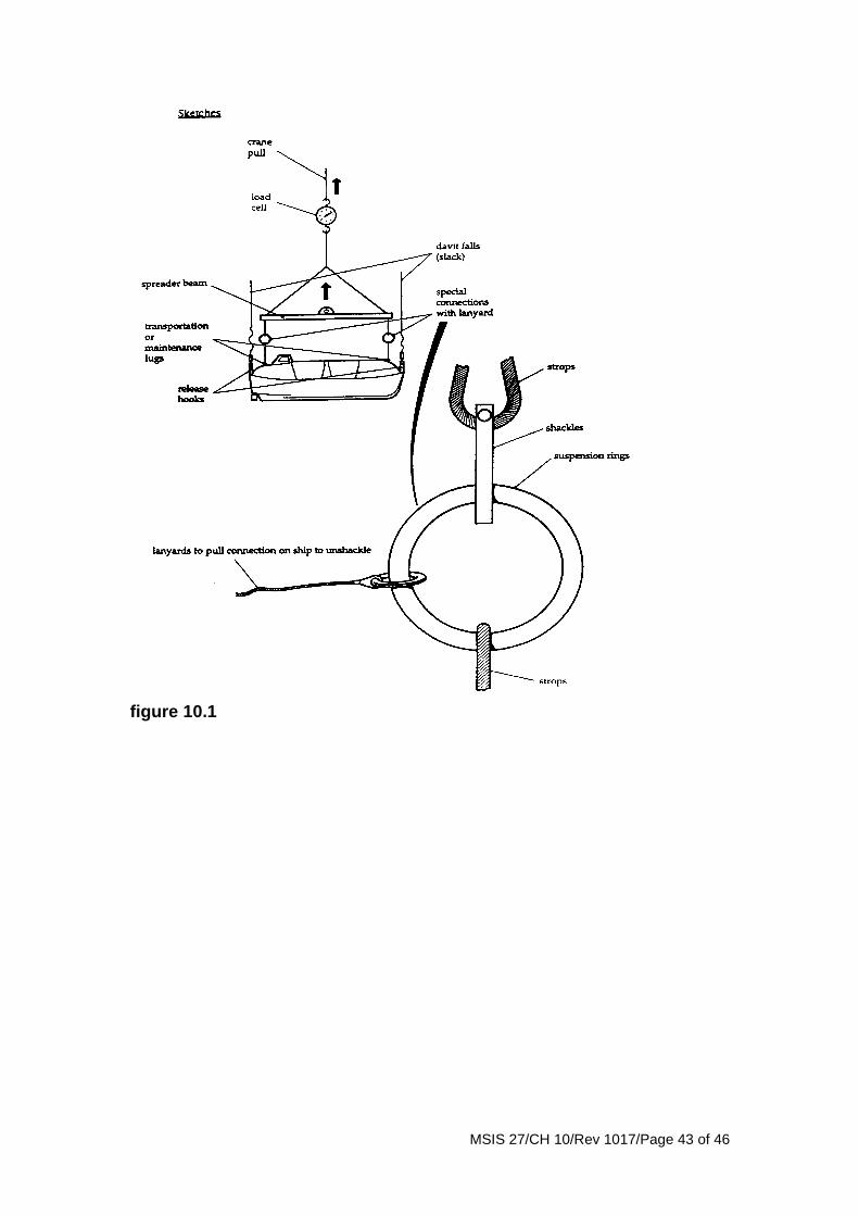
MSIS 27/CH 10/Rev 1017/Page 43 of 46
figure 10.1
MSIS 27/CH 10/Rev 1017/Page 44 of 46
10.43.9.10 The fully loaded boat, without any persons, should then be gently bowed out from the ship side (see 10.43.9.6 above for special bowsing tackle set up for this test only) until falls are vertical and then the shipside ends of the bowsing gear are to be disconnected and the loose ends put back on the boat . 10.43.9.11 The fully loaded boat, without any person, should then be lowered away (observing look-out and other precautions) until maximum lowering speed is reached when the hand brakes should be suddenly applied and tested for effectiveness, followed by thorough visual inspection of heavily stressed parts of the davit and winch structures, including welded areas on deck. When satisfied, the boat should then be gently lowered further by easing the winch hand brake until the boat reaches a position where its keel is just touching (or clear of) the water, where the boat should be stopped. Operating crewmen should then approach the boat under test by another boat and enter it observing relevant precautions with the intention of testing of the on-load release gear. (Note: If the boat has been lowered past this position and it is necessary to hoist it back even by a small amount, the crane is again to be connected up to assist, as the shipboard winch is designed (under SOLAS and MS Regulations) to hoist a lifeboat with only the handling crew and not with full load.) 10.43.9.12 The crew having entered the boat should inspect the release hooks for proper closure (as in the manual) and the fixing arrangements to the relevant boat areas. If satisfactory, the release gear should then be operated according to the instructions manual, to test the on-load mechanism under fully loaded condition. 10.43.9.13 If it is advantageous to unload this way, the fully loaded boat can then be hoisted back by the crane and held in the embarkation position for unloading, followed by the transfer of the light boat to the davits for light boat release tests etc. as described below. 10.43.9.14 If it is advantageous to lighten the boat when waterborne, the weights can be unloaded from the boat, and the boat re-hooked to the falls (observing instructions in the release gear manual) and hoisted just clear of water and stopped for inspection (as in the manual). The light boat should then be released from this position by operation of the release mechanism to test it under the light load condition. 10.43.9.15 The light boat should then be re-hoisted some distance (with precautions and observations as in the manual), and lowered back into the water, and when fully waterborne tested for satisfactory off-load operation of the release gear. 10.43.9.16(Repeat tests with the light boat (maintaining precautions and observations as in the manual) can be made as necessary to satisfy other requirements.)
MSIS 27/CH 10/Rev 1017/Page 45 of 46
10.43.9.17 The opportunity should also be taken to test the painter release mechanism when under load. (Note: The on-load release gear test should not be conducted without a proper purpose nor from a greater height than advised.) 10.43.9.18 The PIC at his discretion need not disconnect the crane but may allow it to remain connected but slackened. In such a case as the shipboard winch lowers the boat, the shore crane must correctly follow the boat movement during the brake test and thereafter down to the waterline when crewmen embarking the boat can disconnect the shore crane from the boat and then test the release mechanism at full load. (Note: While following this method it is also within the bounds of possibility that a sudden load may come on the crane due to failure of normal shipboard launching devices, and therefore minimum SWL of the crane is important). 10.43.9.19 If all the component items have been maintained in the prescribed manner and preliminary inspections of equipment’s, logbooks, certificates etc. do not give any cause to doubt the adequacy of the equipment for the test, then at the discretion of the PIC the assistance of the additional crane may be waived, and the PIC may institute other means to enhance safety (e.g. the final 10 or 20% of the loading may take the form of suitable water bags or drums close to the boat entrances which may be filled by a hose from the ship. Some companies produce water bag systems which can be laid out in empty condition and strapped to the boat to simulate full loading, and these bags can then be filled up from the shipside without the necessity to enter the boat). 10.43.9.20 Some older type lifeboats may not be fitted with on-load release gears. It is to be noted that the five yearly test is also required for such a boat and its launching appliance. 10.43.9.21 Lifeboats on vessels built before 1 January 1999 which are not attached to davits should be tested every five years by being attached to a device capable of putting the equipped boat and a crew of two in the water. If the device is not capable of putting the boat in the water with its complement of persons, then other suitable means shall be provided for embarking persons into the boat (see 10.42.8.1). 10.43.9.22 Some individual shipowners in conjunction with lifeboat manufacturers and local MCA offices have devised alternative equivalent means for the load test which basically consist of: 10.43.9.23 With respect to the 5 yearly load test of lifeboats operators now have two options available to them:
• Option 1
o Test the lifeboat, release mechanism and winch brake as a whole by testing the launching appliance, winch and brakes, lifeboat disengaging gears and lifeboat by loading the lifeboat to 1.1 times the total mass of the lifeboat when loaded to with its
MSIS 27/CH 10/Rev 1017/Page 46 of 46
full compliment of persons and equipment. The lifeboat shall then be turned out and lowered, during which the winch brake shall be operationally tested.
• Option 2
o Test the lifeboat, release mechanism and winch brake as separate entities by
o A static load test of the lifeboat loaded to 1.1 times the total mass of the lifeboat when loaded with its full compliment of persons and equipment.
o Using a hydraulic test device a load of 1.1 times the total mass of the lifeboat when loaded with its full compliment of persons and equipment shall be applied to the release mechanism and the release mechanism shall be operationally tested under load.
o The lifeboat launching appliance shall be loaded (using a spreader bar) to 1.1 times the total mass of the lifeboat when loaded with its full compliment of persons and equipment and the winch brake shall be operationally tested by lowering the weight and applying the brake."
10.43.9.24 If the release hooks are of the on-load type, if it was carried out above water, the boat can be lightened to 100% full load, and the release gear operated at fully loaded condition. If the test was done in a workshop, then when the light boat is resting on chocks on the workshop floor, hydraulic or mechanical jack loads can be set up between the hooks and the boat structure (provided the structure is strong enough for this purpose) and when the load on the hooks represent 100% fully loaded boat (this needs to be confirmed by hydraulic pressure or load cell), the central release gear can be operated to test simultaneous and satisfactory release at full load. 10.43.9.25 If the release hooks are of the on-load type and the 100% load release test cannot be carried out, the light boat is transferred to the ship and connected to its davits. The light boat is then lowered to the position just above water and held there for 100% loading to enable the fully loaded on-load release gear test to be performed. 10.43.9.26 Further tests with the light boat being handled by the shipboard davit are made to satisfy off-load release tests and other requirements. 10.43.10 Lifeboat and rescue boat painter release gears The statutory requirements for painter release gears installed on lifeboats and rescue boats are contained in the LSA Code and Schedule 2, Part 1, paragraph 5.6 of MSN 1676(M).