Chapter 10 HVAC&R CONTROLS 10.1...
18
Chapter 10 HVAC&R CONTROLS 10.1 CONTEXT Controls provide the critical link between HVAC design intent, HVAC&R equipment and systems, and the operating building. Controls are an integral part of the design of an HVAC&R system. They implement design intent by operating the HVAC equipment as required. Inappropriate or inoperative controls can cancel out good design and construction and amplify occupant discontent with a building and its systems. It is imperative that controls be designed and implemented correctly. To provide a complete system solution, an HVAC&R designer must consider how controls will make all parts of the system function. Controls are instrumental in obtaining an energy efficient building. Herzog and Carmody (1996) put this fairly simply: equipment should operate as intended, when intended, to the extent intended. Anything else is inefficient. There is currently growing interest in controls as a contributor to green building status. The growing complexity and proprietary nature of building controls, counteracted somewhat by improvements in control capabilities and computerization, are important issues that affect the role of HVAC&R controls in the design and commissioning processes and ultimate building success. 10.2 INTRODUCTION This chapter outlines the fundamentals of controls and illustrates principles for providing reliable and easily maintainable control systems for a variety of air-conditioning systems. Such control is required to match system operation with the need for space conditioning. The simplest control is an on/off operation typical of residential applications where, as a thermostat senses an increase in room temperature the air conditioner is switched on, and as the temperature falls it is switched off. Most large HVAC&R systems, however, use modulating controls, i.e., controls that vary the output of the equipment being controlled, to provide for the control of temperature, humidity, and air quality in various spaces in a building. 10.3 TERMINOLOGY Figure 10-1 provides the legend for all the figures in this chapter. Figure 10-2 shows a simple cooling coil control scheme. The basic elements of the system include a sensor, that measures a control variable—in this case, air temperature in the duct. The controller compares the sensed value with the setpoint. The difference between the measured variable and the setpoint is called the error. The error signal is processed to change the output from the controller. In this case, the output goes to a valve that modulates the flow of water in the coil, thereby changing the temperature of the air leaving the coil. The
Transcript of Chapter 10 HVAC&R CONTROLS 10.1...
Chapter 10 HVAC&R CONTROLS 10.1 CONTEXT Controls provide the critical link between HVAC design intent, HVAC&R equipment and systems, and the operating building. Controls are an integral part of the design of an HVAC&R system. They implement design intent by operating the HVAC equipment as required. Inappropriate or inoperative controls can cancel out good design and construction and amplify occupant discontent with a building and its systems. It is imperative that controls be designed and implemented correctly. To provide a complete system solution, an HVAC&R designer must consider how controls will make all parts of the system function. Controls are instrumental in obtaining an energy efficient building. Herzog and Carmody (1996) put this fairly simply: equipment should operate as intended, when intended, to the extent intended. Anything else is inefficient. There is currently growing interest in controls as a contributor to green building status. The growing complexity and proprietary nature of building controls, counteracted somewhat by improvements in control capabilities and computerization, are important issues that affect the role of HVAC&R controls in the design and commissioning processes and ultimate building success. 10.2 INTRODUCTION This chapter outlines the fundamentals of controls and illustrates principles for providing reliable and easily maintainable control systems for a variety of air-conditioning systems. Such control is required to match system operation with the need for space conditioning. The simplest control is an on/off operation typical of residential applications where, as a thermostat senses an increase in room temperature the air conditioner is switched on, and as the temperature falls it is switched off. Most large HVAC&R systems, however, use modulating controls, i.e., controls that vary the output of the equipment being controlled, to provide for the control of temperature, humidity, and air quality in various spaces in a building. 10.3 TERMINOLOGY Figure 10-1 provides the legend for all the figures in this chapter. Figure 10-2 shows a simple cooling coil control scheme. The basic elements of the system include a sensor, that measures a control variable—in this case, air temperature in the duct. The controller compares the sensed value with the setpoint. The difference between the measured variable and the setpoint is called the error. The error signal is processed to change the output from the controller. In this case, the output goes to a valve that modulates the flow of water in the coil, thereby changing the temperature of the air leaving the coil. The

process by which the controller output is influenced by the sensed variable that it controls is called feedback. Fig. 10-1 Legend for Control System Schematic Diagrams. Two types of feedback control strategies commonly used in HVAC&R applications are proportional control and proportional plus integral (PI) control. With proportional control, the controller output varies in proportion to the error. In mathematical terms, the controller output is: 0 = A + Kp e (10-1) where, A = a constant defining what the output should be when the error is zero Kp = proportional gain e = error 0 = output Fig. 10-2 Elements of a Basic Control System. For example, if a proportional controller were installed to control the temperature leaving a chilled water cooling coil and if the output ranged from 0 to 100%, then A might be 50 and Kp might be 10. Under these conditions, the output from the controller would be 100% when the leaving coil temperature was 5° above the setpoint, 50% when the temperature and setpoint were the same, and 0% when the temperature was 5° below the setpoint. It would take a 10° change in the leaving coil temperature to cause a 100% change in the controller output. This is called the throttling range of the controller. As this example suggests, the controlled variable is only rarely at the setpoint when proportional control is used. As the name implies, proportional plus integral (PI) control adds integral control action. In mathematical terms 0 = A + (Kp)(e) + Ki ∫ edt (10-2) where Ki is the integral gain. By integrating the error signal over time, the output from the controller is increasing or decreasing any time the error is not zero. This forces the error to zero as steady state is reached. 10.4 CONTROL TYPES Three types of control hardware are used in HVAC&R systems—pneumatic, analog electronic, and direct digital control. Historically, pneumatic controls were used in most large building applications. They are reasonably well understood by designers and maintenance personnel, which was a compelling reason for their use. A second advantage
Walter Grondzik
Highlight
Walter Grondzik
Highlight
Walter Grondzik
Note
integral sign is missing in printed text
Walter Grondzik
Note
this is 8.2 in printed text (incorrect)

was that pneumatic valve and damper actuators, besides being inherently modulating, are inexpensive and reliable when compared to the electric motors and gears required to produce the same control force with electric actuation. Most pneumatic control equipment, however, requires a very clean source of supply air. The air must be dry and free of oil. While it may not be difficult to install a system with clean air, one failure or mistake, such as overfilling a compressor with oil, can permanently foul an entire pneumatic system. Another potential disadvantage of pneumatic controls is that they are not particularly precise. Usually, field calibration is required in order to obtain acceptable accuracy, and periodic recalibration of the pneumatic instruments is required. Modern analog electronic control equipment has several advantages. Power is provided electrically, and there are no air compressors, driers, or filters to maintain. Signals flow at the speed of light, and controllers essentially have an instantaneous response (signal processing is instantaneous; temperature sensors and motors still have time constants). Electronic devices can be extremely accurate and free of drift. Resistance temperature detectors made of platinum, nickel, or other metals manufactured to tolerances of 0.5°F [0.3°C] are relatively inexpensive, do not require field calibration, and are drift free. They are also inexpensive, and it is easy to display electronic signals using digital readouts, providing for ready diagnostics. Another advantage is that it is relatively easy to implement proportional plus integral (PI) control electronically. PI control has important energy-saving advantages that will be discussed later. In the past, electronic control systems were often more expensive than pneumatic systems, partly because of the high cost of electric valve and damper motors. Electronic control systems are now, however, very competitive with pneumatic systems, and can be cheaper when integrated with a building automation system (BAS) because many sensors can perform control and automation functions, whereas additional sensors are required for BAS functions with pneumatic systems. A problem with electronic control hardware is that many different types of systems are in use. For example, some companies use inexpensive thermistor temperature sensors while another uses platinum or nickel. One company may use pulsed voltages to control actuators, while others use 0-9 or 2-10 volts. Some HVAC&R control companies use equipment that follows industrial control practice (platinum resistance temperature sensors and 2-10 volt and 4-20 milliamp control signals). This practice makes components interchangeable and gives designers access to a variety of high-quality industrial sensors and transducers. ASHRAE has stepped into this area of design with the development of Standard 135-2004: BACnet, which provides a protocol for data communication services in building automation and control systems (ASHRAE 2004). Direct digital control (DDC) has become the standard in control systems. Large integrated systems as well as small-scale control units for single-fan systems are available for both new and retrofit applications. DDC accepts analog electronic inputs from appropriate sensors, converts them to digital, uses these digitized signals to produce digital outputs via software control algorithms resident in a local microprocessor, and, finally, converts the digital output signals to analog electronic signals to drive control

actuators that may be electrical or pneumatic. Figure 10-3 presents a schematic diagram of the direct digital control system concept. Fig. 10-3 Direct Digital Control Concept. Perhaps the greatest single advantage of DDC is the flexibility it provides because control is implemented through software rather than hardware. Time sequencing, reset control, PI loops, economizer cycles, and a variety of other operational schemes are accomplished by programming a microprocessor, not by modifying or adding hardware. Of course, with this power comes the designer's responsibility to avoid unnecessary complexity. Another benefit of direct digital control is precision and a complete absence of controller drift. For example, once a temperature setpoint is entered into a digital controller, it remains in the microprocessor's memory unambiguously until it is changed by an operator or until the controller fails. The concept of recalibration is simply not part of digital hardware, and maintenance should be required only when the hardware fails. All problems do not vanish, however, with direct digital control. Analog sensors may still require periodic recalibration. A serious drawback of DDC equipment is a proliferation of programming languages and protocols, making DDC system commissioning and maintenance difficult, particularly since the user interface into the nuts-and-bolts of the controls logic is often not user friendly. Programming of controls is also an issue in that it is often not transparent to the design team and/or readily available for review by the design and commissioning team. Controls programming is moving out of the design office and into the hands of specialists, thus becoming a less integral part of the design process to the potential detriment of integrated design. 10.5 CONTROL STRATEGIES Formerly, many details of control system design were left to the discretion of the contractor. This is no longer true, as the costs of building operation have escalated (largely as a result of increases in energy costs), concern for green building design has escalated (via the impact of the US Green Building Council’s LEED rating system), and control systems have become more complicated. Today, HVAC&R designers must be intimately familiar with the concepts and details of control systems and must be acutely aware of how their design features affect operation and maintenance. Building owners and operators want reliable and easily maintainable control systems. This contradicts the move toward custom controls programming. To meet these conflicting requirements, designers must provide a complete conceptual design for the control system. This includes: ■ The control sequence of operation. ■ A control logic diagram. ■ Ladder diagrams showing the interactions between the various parts of the system.

■ A plan that allows the building and its air-conditioning systems to be put into operation and commissioned.
■ Clear and useful operations and maintenance information. Controls for a number of HVAC&R systems are discussed in the following sections, and examples of control sequences are given in Appendix G. The control schematics provided usually assume that electronic temperature sensing and control is to be used, but that it is interfaced with pneumatic actuators. Designers who choose different control hardware must make the appropriate mental adjustments to the diagrams—although the underlying logic remains generally unchanged. 10.5.1 VAV Systems Figure 10-4 shows a complete control system schematic for a VAV system consisting of the following subsystems: individual room air temperature control, supply air temperature control, mixed air temperature control, and duct static pressure control. Room air temperature control is achieved via VAV boxes controlled by room thermostats. Thermostats and actuators are used to modulate the air supply flow rate in response to room temperature. Most VAV boxes also incorporate flow sensors to allow the box to maintain control of flow rate under varying upstream duct pressures, and provide minimum and maximum airflow settings. VAV boxes that maintain a set airflow regardless of inlet static pressure are referred to as “pressure independent” terminals. If the airflow through a VAV box does change with changing inlet static pressure, the box is referred to as a “pressure dependent” terminal. System-powered or self-powered (deriving motive power from duct pressure only) VAV boxes are also available, although not commonly used. Some of these devices require substantial duct pressure to operate properly. If they are being considered, it may be advisable to require independent performance tests before approving them for installation. Heating is provided where required by reheat coils at the terminal boxes or by baseboard convectors. The heating is controlled either by the room thermostat or by an outdoor air temperature sensor, as described in Appendix C. Baseboard convectors or small fan-coil units (located at floor level or above the ceiling) are a preferred approach for heating exterior zones, since their use permits lower minimum airflow settings on the VAV boxes and allows for building warm-up and night setback heating without turning on the air-handling system. Supply air temperature control should be accomplished using a temperature sensor, a proportional plus integral (PI) controller, appropriate transducers, and a two-way throttling or three-way mixing valve on the cooling coil—as shown in Figure 10-4. Commissioning plans should include detailed descriptions of how to test the control system for stable operation under low and high airflow conditions and cooling loads. Temperature sensors should be located far enough downstream from the fan discharge to

ensure adequate mixing (but not further than 25 ft [7.6 m]), and their locations should be shown on the control drawings. Outdoor and return air dampers should be controlled to achieve the appropriate temperature. This is done by a temperature sensor connected to a PI controller that modulates the dampers. The setpoint of the mixed air temperature controller should be lower than the setpoint of the supply air temperature controller by the value of the temperature rise across the fan. Two temperature sensors in the outdoor and return air streams can be used in conjunction with a comparator that evaluates the temperature signals and returns the outdoor and relief air dampers to their minimum positions whenever the outdoor air is warmer (or has a higher enthalpy) than the return air. Fig. 10-4 Control Schematic for a VAV System. Construction details showing the connection of outdoor and return air ducts to the air-handling equipment should be included in the drawings. Baffles or other devices should be used to minimize stratification in this part of the duct system. Complete mixing of the outdoor and return air is necessary if the mixed air temperature sensor is to sense a meaningful value. Modulation of fan speed (or an alternative technique) is usually employed in VAV systems to achieve energy efficiency, avoid potentially damaging duct pressures, and permit the VAV boxes to perform adequately. Consider PI control for this application. Varying the fan speed is the preferred control method. Not only is it the most efficient, but it can also modulate to lower airflow rates and avoids the problems of stuck or broken vanes or linkages. The commissioning plan should include a requirement to test the stability of the control system with all the VAV boxes at their minimum airflow setting. If fans can produce potentially damaging duct pressures, a high-pressure limit switch or blowout panel should be provided. Mutammara and Hittle (1990) compared the energy consumption in high-rise office buildings in five different climates under a variety of control strategies. They found that, except in hot, humid climates, the most energy-efficient control strategies are: (1) PI control with an economizer, and (2) cold deck reset for perimeter zones. Cold deck reset involves the use of room thermostat signals to reset the discharge air temperature (discriminating control, see Section 9.3.3). While this system can provide additional energy efficiency, reliability is a serious question. Failure of an individual room thermostat or tampering by an occupant could cause the air temperatures to be adjusted to an unreasonably low value. Fan energy also increases, which might lead to an increase in operating cost. Thus, the simpler fixed deck temperature with PI control and an economizer may be more attractive. Economizers are not recommended for hot, humid climates because the number of hours during which they can be used effectively is small. Instead, minimum outdoor air is provided for quality ventilation. Return fans should generally be avoided in VAV systems because good control of return fans is difficult and involves sophisticated hardware. Return fans also require more energy than relief fans, as shown in Section 6.8.2.4. If, however, a return fan is absolutely
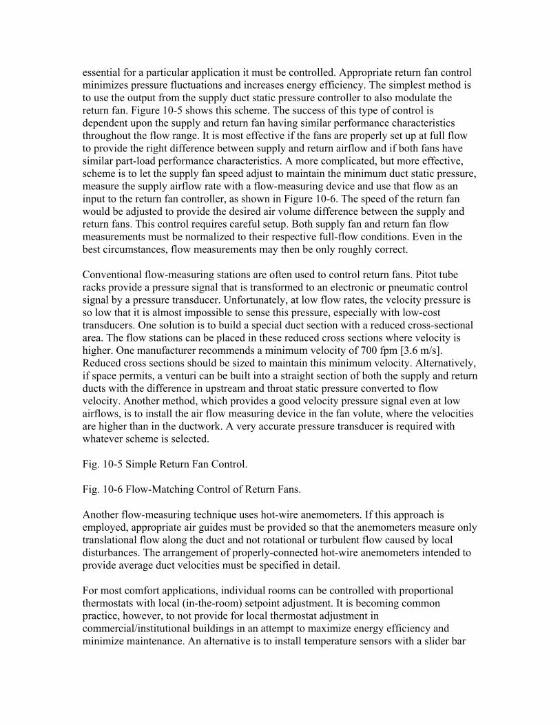
essential for a particular application it must be controlled. Appropriate return fan control minimizes pressure fluctuations and increases energy efficiency. The simplest method is to use the output from the supply duct static pressure controller to also modulate the return fan. Figure 10-5 shows this scheme. The success of this type of control is dependent upon the supply and return fan having similar performance characteristics throughout the flow range. It is most effective if the fans are properly set up at full flow to provide the right difference between supply and return airflow and if both fans have similar part-load performance characteristics. A more complicated, but more effective, scheme is to let the supply fan speed adjust to maintain the minimum duct static pressure, measure the supply airflow rate with a flow-measuring device and use that flow as an input to the return fan controller, as shown in Figure 10-6. The speed of the return fan would be adjusted to provide the desired air volume difference between the supply and return fans. This control requires careful setup. Both supply fan and return fan flow measurements must be normalized to their respective full-flow conditions. Even in the best circumstances, flow measurements may then be only roughly correct. Conventional flow-measuring stations are often used to control return fans. Pitot tube racks provide a pressure signal that is transformed to an electronic or pneumatic control signal by a pressure transducer. Unfortunately, at low flow rates, the velocity pressure is so low that it is almost impossible to sense this pressure, especially with low-cost transducers. One solution is to build a special duct section with a reduced cross-sectional area. The flow stations can be placed in these reduced cross sections where velocity is higher. One manufacturer recommends a minimum velocity of 700 fpm [3.6 m/s]. Reduced cross sections should be sized to maintain this minimum velocity. Alternatively, if space permits, a venturi can be built into a straight section of both the supply and return ducts with the difference in upstream and throat static pressure converted to flow velocity. Another method, which provides a good velocity pressure signal even at low airflows, is to install the air flow measuring device in the fan volute, where the velocities are higher than in the ductwork. A very accurate pressure transducer is required with whatever scheme is selected. Fig. 10-5 Simple Return Fan Control. Fig. 10-6 Flow-Matching Control of Return Fans. Another flow-measuring technique uses hot-wire anemometers. If this approach is employed, appropriate air guides must be provided so that the anemometers measure only translational flow along the duct and not rotational or turbulent flow caused by local disturbances. The arrangement of properly-connected hot-wire anemometers intended to provide average duct velocities must be specified in detail. For most comfort applications, individual rooms can be controlled with proportional thermostats with local (in-the-room) setpoint adjustment. It is becoming common practice, however, to not provide for local thermostat adjustment in commercial/institutional buildings in an attempt to maximize energy efficiency and minimize maintenance. An alternative is to install temperature sensors with a slider bar

that permits local adjustment. The slider bar can be programmed to establish how much temperature adjustment is allowed. The temperature control profile for the VAV dampers and heating coil (or baseboard heaters) should be as shown in Figures 10-7 and 10-8. Room thermostats should not be located on exterior walls, in dead corners, or in other unsuitable locations where they are likely to be unduly affected by equipment, occupant, or solar radiation loads. The best locations are those that provide some air motion and allow thermostats to sense the average room temperature. The location of all thermostats should be indicated on the plans. If add-on, tamperproof covers are used, they should be constructed to allow free air movement over the thermostat. Metal or plastic box-type security enclosures with minimal air slits should not be used, since they do not provide enough airflow over the thermostat for it to respond rapidly to changing room conditions. If thermostats must be installed on exterior walls, insulating bases should be used and the wall penetration sealed airtight. Fig. 10-7 Room Temperature Control Profile for "Zero Energy Band" Thermostat (temperatures shown are merely suggested values). Fig. 10-8 Room Temperature Control Profile for "Dead Band" Thermostat (temperatures shown are merely suggested values). 10.5.2 Single-Zone, Constant-Volume Air Systems Very small single-zone air-handling units are thermodynamically equivalent to room fan-coil units or residential air-conditioning systems and can be controlled by simple two-position electric or electronic thermostat/valve systems common in this type of unit. For larger single-zone systems, one of the schemes illustrated in Figures 10-9 and 10-11 can be used. Figure 10-9 shows a minimum configuration, which may provide inadequate control and should be used only on closely coupled systems, i.e., systems with relatively short ductwork and high air volume flow rates compared to the room volume. In this scheme, a room or return air temperature sensor is connected to a single proportional controller, which modulates the heating coil valve, mixing dampers, and cooling coil valve in sequence. The temperature control profiles should be as shown in Figure 10-10. The outdoor and return air temperature sensors are used to return the outdoor and return air dampers to the minimum position whenever the outdoor air is warmer (or of higher enthalpy, if enthalpy control is used) than the return air. This economizer cycle should have a hysteresis of up to 2°F [1°C], i.e., the cycle should be initiated or terminated when the outdoor air is 2°F [1°C] cooler or warmer than the return air. The proper sequencing of the valves and dampers is achieved by carefully adjusting the positioners on the equipment. Verification of successful sequencing should be part of the commissioning plan and ongoing operations and maintenance checks. The room temperature sensors should not be located in the return air duct if the return air is drawn through lighting fixtures or in any other
Walter Grondzik
Note
correction to be made to illustration right hand labels (at VAV DAMPER) change CLOSED to OPEN change OPEN to MINIMUM
Walter Grondzik
Note
correction to be made to illustration right hand labels (at VAV DAMPER) change CLOSED to OPEN change OPEN to MINIMUM
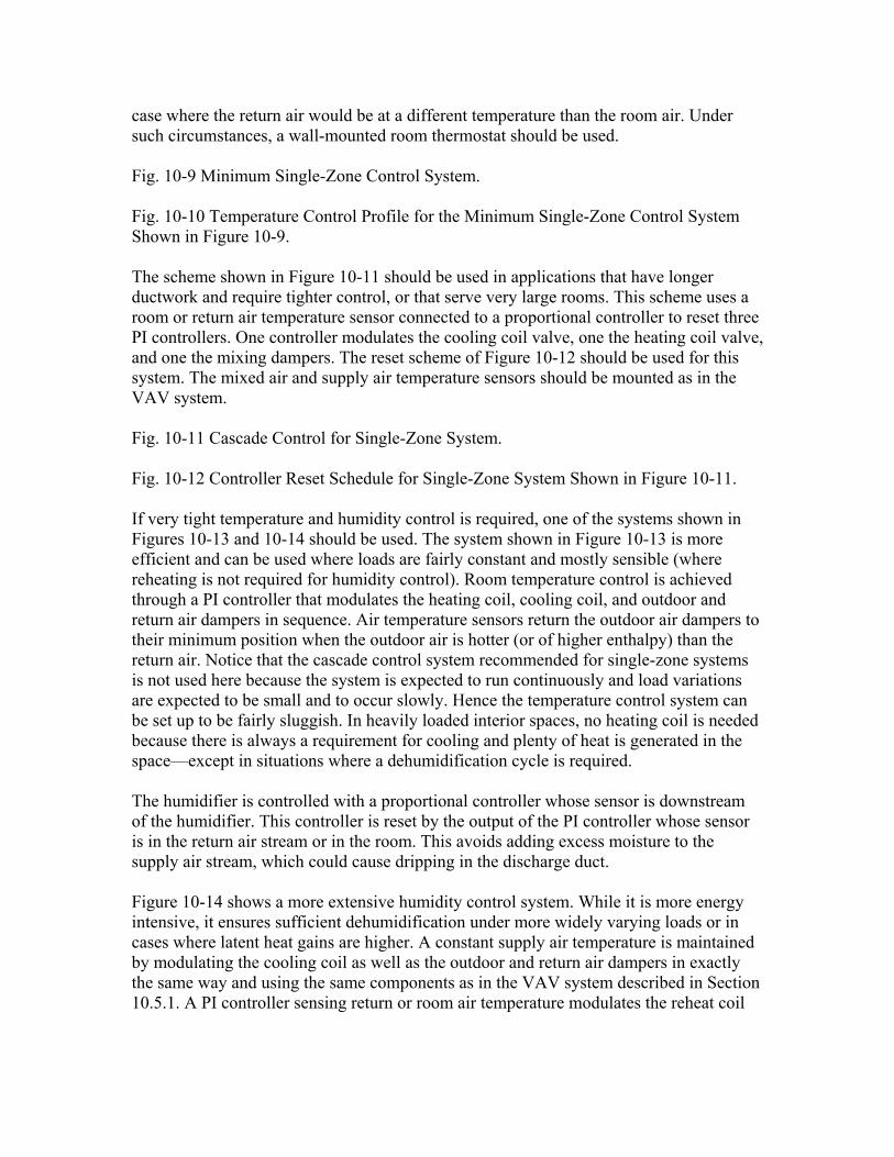
case where the return air would be at a different temperature than the room air. Under such circumstances, a wall-mounted room thermostat should be used. Fig. 10-9 Minimum Single-Zone Control System. Fig. 10-10 Temperature Control Profile for the Minimum Single-Zone Control System Shown in Figure 10-9. The scheme shown in Figure 10-11 should be used in applications that have longer ductwork and require tighter control, or that serve very large rooms. This scheme uses a room or return air temperature sensor connected to a proportional controller to reset three PI controllers. One controller modulates the cooling coil valve, one the heating coil valve, and one the mixing dampers. The reset scheme of Figure 10-12 should be used for this system. The mixed air and supply air temperature sensors should be mounted as in the VAV system. Fig. 10-11 Cascade Control for Single-Zone System. Fig. 10-12 Controller Reset Schedule for Single-Zone System Shown in Figure 10-11. If very tight temperature and humidity control is required, one of the systems shown in Figures 10-13 and 10-14 should be used. The system shown in Figure 10-13 is more efficient and can be used where loads are fairly constant and mostly sensible (where reheating is not required for humidity control). Room temperature control is achieved through a PI controller that modulates the heating coil, cooling coil, and outdoor and return air dampers in sequence. Air temperature sensors return the outdoor air dampers to their minimum position when the outdoor air is hotter (or of higher enthalpy) than the return air. Notice that the cascade control system recommended for single-zone systems is not used here because the system is expected to run continuously and load variations are expected to be small and to occur slowly. Hence the temperature control system can be set up to be fairly sluggish. In heavily loaded interior spaces, no heating coil is needed because there is always a requirement for cooling and plenty of heat is generated in the space—except in situations where a dehumidification cycle is required. The humidifier is controlled with a proportional controller whose sensor is downstream of the humidifier. This controller is reset by the output of the PI controller whose sensor is in the return air stream or in the room. This avoids adding excess moisture to the supply air stream, which could cause dripping in the discharge duct. Figure 10-14 shows a more extensive humidity control system. While it is more energy intensive, it ensures sufficient dehumidification under more widely varying loads or in cases where latent heat gains are higher. A constant supply air temperature is maintained by modulating the cooling coil as well as the outdoor and return air dampers in exactly the same way and using the same components as in the VAV system described in Section 10.5.1. A PI controller sensing return or room air temperature modulates the reheat coil

valve to control the room temperature. The humidifier is controlled as shown in Figure 10-13. Fig. 10-13 Single-Zone System with Precise Temperature Control. Fig. 10-14 Single-Zone System with Precise Temperature and Humidity Control. 10.5.3 Dual-Duct Systems A potential automatic control arrangement for a dual-duct system is shown in Figure 10-15. It is adequate for most installations and can be easily modified to suit particular applications and requirements. The minimum outdoor air damper is open when the fan is running, except when all areas are unoccupied during warm-up. The hot duct temperature is controlled by the submaster hot duct thermostat, which operates the heating coil valve (or valves) in sequence. The control point of this thermostat is reset by the outdoor master thermostat according to a predetermined schedule. The air in the cold duct is maintained at the desired dew-point temperature by the cold duct thermostat, which operates a cooling coil valve. At a predetermined outdoor air temperature, the system is switched to economizer cooling by a two-position switchover thermostat. When outdoor air is used for cooling, the cold duct thermostat controls the operation of the maximum outdoor air, exhaust, and return air dampers through the use of a three-way air valve. This thermostat also controls the operation of the cooling coil when mechanical cooling is required. The control of the central system is simple, since it is asked only to serve as a source of warm and cold dehumidified air. There are numerous possible refinements for operating economies, ventilation optimization, and so forth. Fig. 10-15 Simple Automatic Control for Dual-Duct System. Dual-duct systems with mechanical or automatic flow regulators do not need fan or system static pressure regulation, since each terminal unit compensates for any changes in backpressure. To take full advantage of fan energy savings at reduced flow conditions in dual-duct VAV systems, however, fan regulation is recommended. This also helps to avoid high-pressure-drop noise effects in VAV terminal units and is a more important consideration in dual-fan systems. 10.6 COMPONENTS Control valves must be sized to provide proper control stability and authority. Authority is the ratio of the pressure drop through the wide-open valve to the combined pressure drop through the valve and coil or valve and heat exchanger. Line-size valves are almost always too large. Valve sizes and valve coefficients should be shown on a schedule on the plans. Equal percentage valves (see Section 5.6.2) with a turndown ratio of 20:1 or better are usually needed for most HVAC applications. The authority of control valves
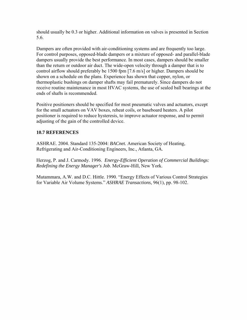
should usually be 0.3 or higher. Additional information on valves is presented in Section 5.6. Dampers are often provided with air-conditioning systems and are frequently too large. For control purposes, opposed-blade dampers or a mixture of opposed- and parallel-blade dampers usually provide the best performance. In most cases, dampers should be smaller than the return or outdoor air duct. The wide-open velocity through a damper that is to control airflow should preferably be 1500 fpm [7.6 m/s] or higher. Dampers should be shown on a schedule on the plans. Experience has shown that copper, nylon, or thermoplastic bushings on damper shafts may fail prematurely. Since dampers do not receive routine maintenance in most HVAC systems, the use of sealed ball bearings at the ends of shafts is recommended. Positive positioners should be specified for most pneumatic valves and actuators, except for the small actuators on VAV boxes, reheat coils, or baseboard heaters. A pilot positioner is required to reduce hysteresis, to improve actuator response, and to permit adjusting of the gain of the controlled device. 10.7 REFERENCES ASHRAE. 2004. Standard 135-2004: BACnet. American Society of Heating, Refrigerating and Air-Conditioning Engineers, Inc., Atlanta, GA. Herzog, P. and J. Carmody. 1996. Energy-Efficient Operation of Commercial Buildings: Redefining the Energy Manager's Job. McGraw-Hill, New York. Mutammara, A.W. and D.C. Hittle. 1990. “Energy Effects of Various Control Strategies for Variable Air Volume Systems.” ASHRAE Transactions, 96(1), pp. 98-102.
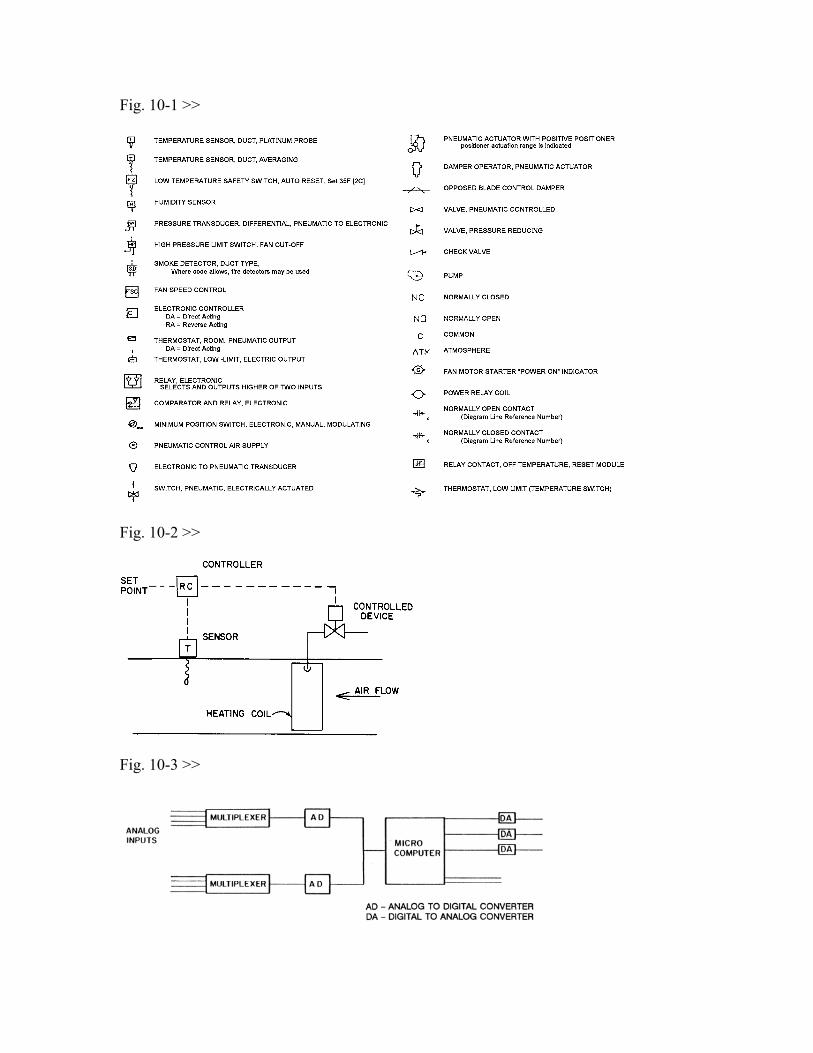
Fig. 10-1 >>
Fig. 10-2 >>
Fig. 10-3 >>
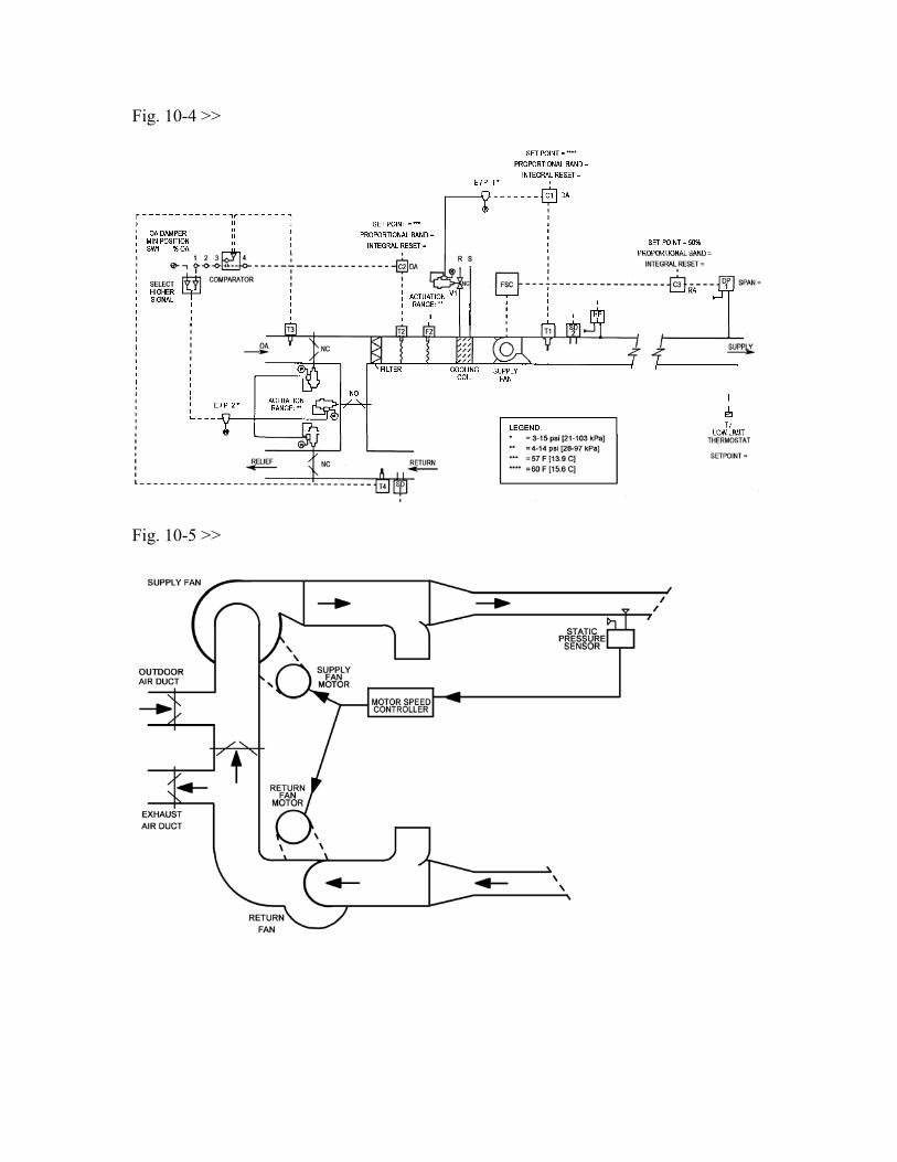
Fig. 10-4 >>
Fig. 10-5 >>

Fig. 10-6 >>
Fig. 10-7 >>
Fig. 10-8 >>

Fig. 10-9 >>
Fig. 10-10 >>
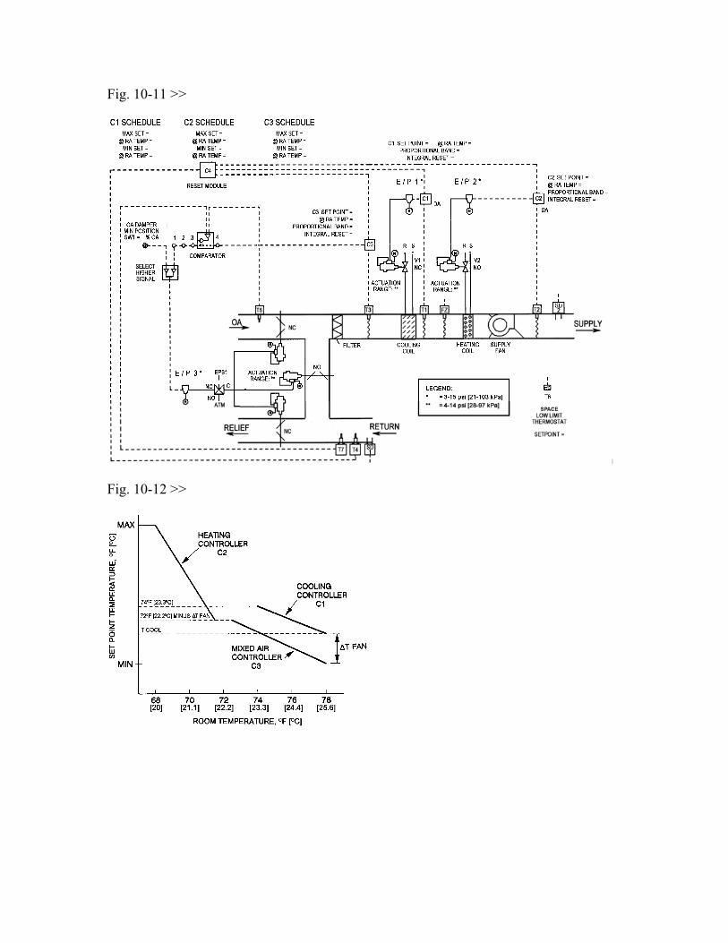
Fig. 10-11 >>
Fig. 10-12 >>
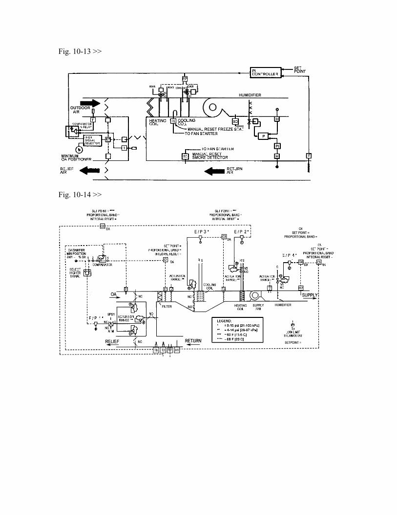
Fig. 10-13 >>
Fig. 10-14 >>

Fig. 10-15 >>