Chapter 10 Diffraction - SKKUicc.skku.ac.kr/~yeonlee/Display Optics/HECHT_10a.pdf · 2012-10-23 ·...
10
Hecht; 11/28/2010; 10-1 Chapter 10 Diffraction 10.1 Preliminary Considerations Diffraction is a deviation of light from rectilinear propagation. It occurs whenever a portion of a wavefront is obstructed. No significant distinction between interference and diffraction . ↑ ↑ Superposition of a few waves, many waves Huygens-Fresnel Principle Every point on a wavefront serves as a source of spherical secondary wavelets with the same frequency. The amplitude of the optical field at a later time is the superposition of all the secondary wavelets. If the wavelength is larger than the aperture, the wave will spread out at a large angle. [Picture P445] A. Opaque Obstructions There is no optical field beyond it. The incident wave and the electron-oscillator fields superimpose to yield zero field beyond the screen. A screen = Apertured screen + Small disk ↓ ↓ Diffraction field + Electron-oscillator field ⇒ Zero field Unpaired electron-oscillator at the rim → Not negligible near the aperture. B. Fraunhofer-Fresnel Diffraction A point source at infinity → Aperture → Screen ↑ ↑ ↑ Distance O l . Distance S l . Diffraction pattern. Plane wave. S l The diffraction pattern Short dist. Same shape as the aperture. Geometrical optics applies. Intermediate Recognizable aperture shape with fringes. Fresnel or Near-field diffraction. Long dist. Smooth pattern with no resemblance to the aperture. Fraunhofer or Far-field diffraction. z Reducing the wavelength. Fraunhofer diffraction → Fresnel diffraction → Geometrical optics The point source closer to the aperture. → Not plane wave at the aperture. → Fresnel diffraction even if S l →∞ Fraunhofer diffraction when 2 / R a λ > R: Smaller distance of O l and S l . a: aperture size.
Transcript of Chapter 10 Diffraction - SKKUicc.skku.ac.kr/~yeonlee/Display Optics/HECHT_10a.pdf · 2012-10-23 ·...

Hecht; 11/28/2010; 10-1
Chapter 10 Diffraction 10.1 Preliminary Considerations Diffraction is a deviation of light from rectilinear propagation. It occurs whenever a portion of a wavefront is obstructed. No significant distinction between interference and diffraction. ↑ ↑ Superposition of a few waves, many waves Huygens-Fresnel Principle Every point on a wavefront serves as a source of spherical secondary wavelets with the same frequency. The amplitude of the optical field at a later time is the superposition of all the secondary wavelets. If the wavelength is larger than the aperture, the wave will spread out at a large angle. [Picture P445] A. Opaque Obstructions There is no optical field beyond it. The incident wave and the electron-oscillator fields superimpose to yield zero field beyond the screen. A screen = Apertured screen + Small disk ↓ ↓ Diffraction field + Electron-oscillator field ⇒ Zero field Unpaired electron-oscillator at the rim → Not negligible near the aperture. B. Fraunhofer-Fresnel Diffraction A point source at infinity → Aperture → Screen ↑ ↑ ↑
Distance Ol . Distance Sl . Diffraction pattern. Plane wave. Sl The diffraction pattern
Short dist. Same shape as the aperture. Geometrical optics applies. Intermediate Recognizable aperture shape with fringes. Fresnel or Near-field diffraction. Long dist. Smooth pattern with no resemblance to the aperture. Fraunhofer or Far-field diffraction.
Reducing the wavelength. Fraunhofer diffraction → Fresnel diffraction → Geometrical optics The point source closer to the aperture. → Not plane wave at the aperture. → Fresnel diffraction even if Sl → ∞ Fraunhofer diffraction when 2 /R a λ> R: Smaller distance of Ol and Sl . a: aperture size.
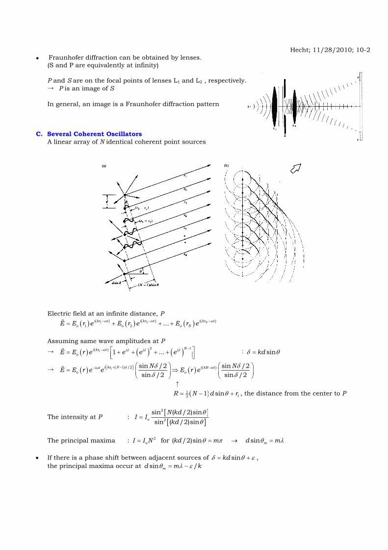
Hecht; 11/28/2010; 10-2 Fraunhofer diffraction can be obtained by lenses.
(S and P are equivalently at infinity)
P and S are on the focal points of lenses L1 and L2 , respectively. → P is an image of S In general, an image is a Fraunhofer diffraction pattern C. Several Coherent Oscillators A linear array of N identical coherent point sources
Electric field at an infinite distance, P ( ) ( ) ( ) ( ) ( ) ( )21
1 2 ... Ni kr ti kr t i kr to o o NE E r e E r e E r eωω ω−− −= + + +
Assuming same wave amplitudes at P
→ ( ) ( ) ( ) ( )12 1
1 ...Ni kr t i i i
oE E r e e e eω δ δ δ −− ⎡ ⎤= + + + +⎢ ⎥⎣ ⎦ : sinkdδ θ=
→ ( ) ( ) ( ) ( )1 1 /2 sin /2 sin /2sin /2 sin /2
i kr N i kR ti to o
N NE E r e e E r eδ ωω δ δδ δ
+ −⎡ ⎤ −− ⎣ ⎦ ⎛ ⎞ ⎛ ⎞= ⇒⎜ ⎟ ⎜ ⎟
⎝ ⎠ ⎝ ⎠
↑ ( )1
12 1 sinR N d rθ= − + , the distance from the center to P
The intensity at P : [ ][ ]
2
2
sin ( /2)sinsin ( /2)sino
N kdI I
kdθθ
=
The principal maxima : 2
oI I N= for ( /2)sin sin mkd m d mθ π θ λ= → = • If there is a phase shift between adjacent sources of sinkdδ θ ε= + , the principal maxima occur at sin /md m kθ λ ε= −
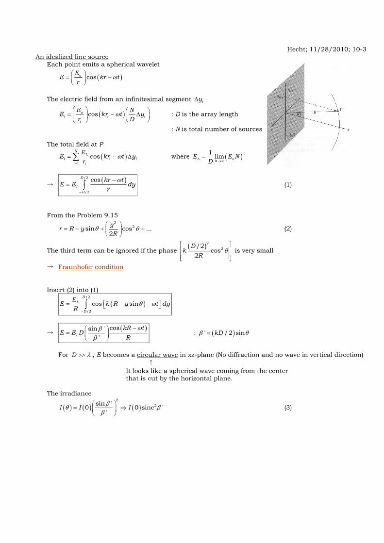
Hecht; 11/28/2010; 10-3 An idealized line source Each point emits a spherical wavelet
( )cos ω⎛ ⎞= −⎜ ⎟⎝ ⎠
oEE kr t
r
The electric field from an infinitesimal segment iyΔ
( )cos ω⎛ ⎞ ⎛ ⎞= − Δ⎜ ⎟ ⎜ ⎟
⎝ ⎠⎝ ⎠o
i i ii
E NE kr t yr D
: D is the array length
: N is total number of sources The total field at P
( )1
cos ω=
= − Δ∑N
Li i i
i i
EE kr t yr
where ( )1 limL oNE E N
D →∞≡
→ ( )/2
/2
cos ω
−
−= ∫
D
LD
kr tE E dy
r (1)
From the Problem 9.15
2
2sin cos ...2yr R yR
θ θ⎛ ⎞
= − + +⎜ ⎟⎝ ⎠
(2)
The third term can be ignored if the phase ( )2 2/2
cos2
θ⎡ ⎤⎢ ⎥⎢ ⎥⎣ ⎦
Dk
R is very small
→ Fraunhofer condition Insert (2) into (1)
( )/2
/2
cos sinθ ω−
= − −⎡ ⎤⎣ ⎦∫D
L
D
EE k R y t dyR
→ ( )cossin '
'L
kR tE E D
Rωβ
β−⎛ ⎞
= ⎜ ⎟⎝ ⎠
: ( )' /2 sinkDβ θ≡
For D λ>> , E becomes a circular wave in xz-plane (No diffraction and no wave in vertical direction) ↑ It looks like a spherical wave coming from the center that is cut by the horizontal plane. The irradiance
( ) ( ) ( )2
2sin '0 0 sinc ''
I I Iβθ ββ
⎛ ⎞= ⇒⎜ ⎟
⎝ ⎠ (3)
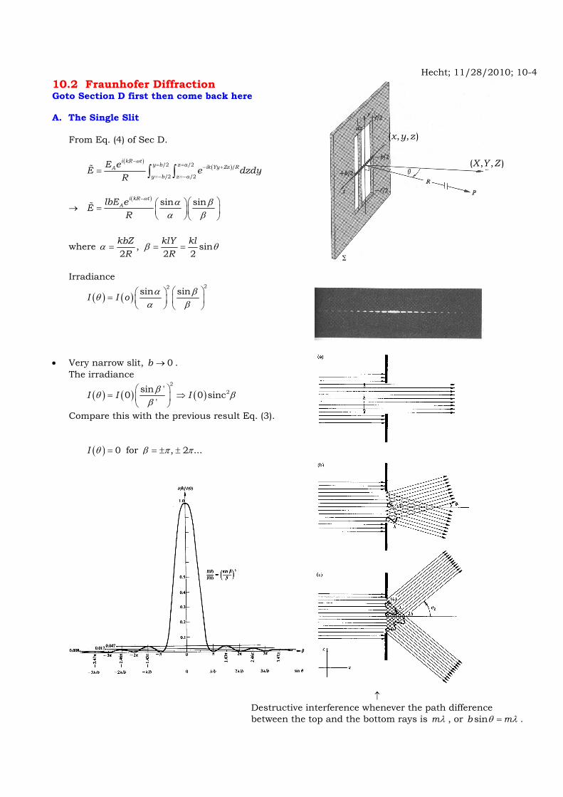
Hecht; 11/28/2010; 10-4 10.2 Fraunhofer Diffraction Goto Section D first then come back here A. The Single Slit
From Eq. (4) of Sec D.
( )
( )/2 /2 /
/2 /2
i kR ty b z a ik Yy Zz RAy b z a
E eE e dzdyR
ω−= = − +
=− =−= ∫ ∫
→ ( ) sin sini kR t
AlbE eER
ω α βα β
− ⎛ ⎞⎛ ⎞= ⎜ ⎟⎜ ⎟⎝ ⎠ ⎝ ⎠
where , sin2 2 2kbZ klY kl
R Rα β θ= = =
Irradiance
( ) ( )22sin sinI I o α βθ
α β⎛ ⎞⎛ ⎞= ⎜ ⎟⎜ ⎟
⎝ ⎠ ⎝ ⎠
• Very narrow slit, 0b → . The irradiance
( ) ( ) ( )2
2sin '0 0 sinc'
I I Iβθ ββ
⎛ ⎞= ⇒⎜ ⎟
⎝ ⎠
Compare this with the previous result Eq. (3).
( ) 0I θ = for , 2 ...β π π= ± ±
↑ Destructive interference whenever the path difference between the top and the bottom rays is mλ , or sinb mθ λ= .
( , , )X Y Z
( , , )x y z

Hecht; 11/28/2010; 10-5 B. The Double Slits Waves from each slit will interfere
The total electric field at P using Eq. (4)
( ) ( )/2 /2 /2 /2
/ /
/2 /2 /2 /2
l b l a bik Yy Zz R ik Yy Zz R
l b l a b
E C e dzdy C e dzdy+
− + − +
− − − −
= +∫ ∫ ∫ ∫
→ ( ) ( )/2 /2
/ /
/2 /2
sin b a bik Zz R ik Zz R
b a b
E lC e dz e dzββ
+− −
− −
⎡ ⎤⎛ ⎞= +⎢ ⎥⎜ ⎟
⎝ ⎠ ⎢ ⎥⎣ ⎦∫ ∫ :
2klY
Rβ =
→ sin sin2 cosiE lbCe γ β α γβ α
− ⎛ ⎞ ⎛ ⎞= ⎜ ⎟ ⎜ ⎟⎝ ⎠⎝ ⎠
: sin2 2kbZ kb
Rα θ= = , sin
2 2kaZ ka
Rγ θ= =
The irradiance
( )2 2
2sin sin4 cosoI I β αθ γβ α
⎛ ⎞ ⎛ ⎞= ⎜ ⎟ ⎜ ⎟⎝ ⎠⎝ ⎠
: oI is the irradiance from each slit
↑ ↑ ↑ Diffraction. Interference. An interference maximum and a diffraction minimum correspond to the same θ → Missing order For a mb= , there are m bright fringes within the central diffraction peak
( , , )X Y Z
( , , )x y z

Hecht; 11/28/2010; 10-6 C. Diffraction by Many Slits The total electric field at P
( ) ( ) ( ) ( )( 1) /2/2 /2 /2 /2 /2 2 /2 /2
/2 /2 /2 /2 /2 2 /2 /2 ( 1) /2
...N a bl b l a b l a b l
l b l a b l a b l N a b
E C F z dzdy C F z dzdy C F z dzdy C F z dzdy− ++ +
− − − − − − − − −
= + + + +∫ ∫ ∫ ∫ ∫ ∫ ∫ ∫
→ ( ) ( )( )2 1/ / /sin sin 1 ...NikZa R ikZa R ikZa RE lbC e e eβ α
β α−− − −⎛ ⎞ ⎛ ⎞ ⎡ ⎤= + + + +⎜ ⎟ ⎜ ⎟ ⎢ ⎥⎣ ⎦⎝ ⎠⎝ ⎠
→ sin sin sinsin
i N NE lbCe γ β α γβ α γ
− ⎛ ⎞ ⎛ ⎞= ⎜ ⎟ ⎜ ⎟⎝ ⎠⎝ ⎠
where 2klY
Rβ = , sin
2 2kbZ kb
Rα θ= = , sin
2 2kaZ ka
Rγ θ= =
The irradiance
( ) ( ) 2 22
2
0 sin sin sinsin
I NIN
β α γθβ α γ
⎛ ⎞ ⎡ ⎤⎛ ⎞= ⎜ ⎟ ⎜ ⎟ ⎢ ⎥⎝ ⎠⎝ ⎠ ⎣ ⎦
(0)I , peak of the total I at the screen center oI , peak irradiance by one slit The principal maxima for 0sinγ = , 0, , 2 ...γ π π= ± ±
(N-1) minima for 0sinNγ = , 2 3, , ...N N Nπ π πγ = ± ± ±
A subsidiary maxima at 3 5, ...2 2N Nπ πγ = ± ±
The irradiance of the first subsidiary maximum
22 1(0)
3 22I I
π⎛ ⎞≈ ≈⎜ ⎟⎝ ⎠

Hecht; 11/28/2010; 10-7 D. The Rectangular Aperture
a
bz
x
y
dSP(X,Y,Z)
R
r
The differential electric field at P from a differential source AE dS
( )( )i kr t
AedE E dS
r
ω−
=
Radial distance
( ) ( ) ( ) ( ) ( )2 22 2 2 2 2 21 / 2 / 1 /r X Y y Z z R y z R Yy Zz R R Yy Zz R⎡ ⎤= + − + − = + + − + ≈ − +⎣ ⎦
↑ In the Fraunhofer region R → ∞ The total electric field at P
( )
( )/2 /2 /
/2 /2
i kR ty b z a ik Yy Zz RAy b z a
E eE e dydzR
ω−= = − +
=− =−= ∫ ∫ (4)
→ ( ) sin ' sin '
'
i kR tAabE eER
ω α βα β
− ⎛ ⎞⎛ ⎞= ⎜ ⎟⎜ ⎟⎝ ⎠ ⎝ ⎠
: ' /2 , ' /2kaZ R kbY Rα β= =
The irradiance
22sin ' sin '( , ) (0)
' 'I Y Z I α β
α β⎛ ⎞⎛ ⎞= ⎜ ⎟⎜ ⎟
⎝ ⎠ ⎝ ⎠
The maxima along 'β axis : 2
(0)'m
IIβ
= for 3 5' , ,...2 2mπ πβ = ± ± and ' 0α =
The maxima along 'α axis : 2
(0)'m
IIα
= for 3 5' , ,...2 2mπ πα = ± ± and ' 0β =
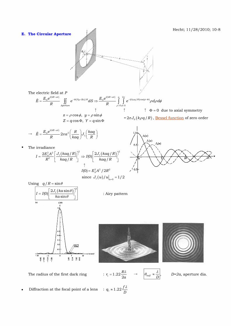
Hecht; 11/28/2010; 10-8 E. The Circular Aperture
The electric field at P
( )
( )( )
( ) ( )2
/ / cos
0 0
i kR t i kR t aik Yy Zz R i k q RA A
Aperture
E e E eE e dS e d dR R
ω ω πρ φ
ρ φ
ρ ρ φ− −
− + − −Φ
= =
= ⇒∫∫ ∫ ∫
↑ ↑ ↑ 0Φ = due to axial symmetry
cos , sincos , sin
z yZ q Y q
ρ φ ρ φ= == Φ = Φ
= ( )02 /J k q Rπ ρ , Bessel function of zero order
→ ( )
212
i kR tAE e R kaqE a J
R kaq R
ω
π− ⎛ ⎞ ⎛ ⎞= ⎜ ⎟ ⎜ ⎟
⎝ ⎠⎝ ⎠
The irradiance
( ) ( )2 22 2
1 12
/ 2 /2(0)
/ /A J kaq R J kaq RE AI I
kaq R kaq RR⎡ ⎤ ⎡ ⎤
= ⇒⎢ ⎥ ⎢ ⎥⎣ ⎦ ⎣ ⎦
↑ 2 2 2(0) /2AI E A R=
since ( )1 0/ 1/2
uJ u u
==
Using / sinq R θ=
( ) 2
12 sin(0)
sinJ ka
I Ika
θθ
⎡ ⎤= ⎢ ⎥
⎣ ⎦ : Airy pattern
The radius of the first dark ring : 1 1.222Rr
aλ
= → half Dλθ ≈ , D=2a, aperture dia.
Diffraction at the focal point of a lens : 1 1.22 fqDλ
≈
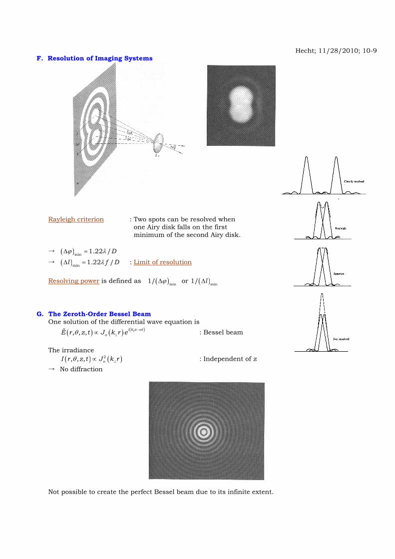
Hecht; 11/28/2010; 10-9 F. Resolution of Imaging Systems
Rayleigh criterion : Two spots can be resolved when one Airy disk falls on the first minimum of the second Airy disk. → ( )min
1.22 /Dϕ λΔ =
→ ( )min1.22 /l f DλΔ = : Limit of resolution
Resolving power is defined as ( )min
1/ ϕΔ or ( )min1/ lΔ
G. The Zeroth-Order Bessel Beam One solution of the differential wave equation is ( ) ( ) ( ), , , i k z t
oE r z t J k r e ωθ −⊥∝ : Bessel beam
The irradiance ( ) ( )2, , , oI r z t J k rθ ⊥∝ : Independent of z → No diffraction
Not possible to create the perfect Bessel beam due to its infinite extent.

Hecht; 11/28/2010; 10-10 H. The Diffraction Grating A diffraction grating produces periodic alterations in the phase and/or amplitude of the incident wave.
Transmission amplitude grating Reflection phase grating A multiple-slits modulates the amplitude. Ruling on a reflective surface Transmission phase grating Ruling of parallel notches on a flat glass plate. (Periodic change of the refractive index)
Grating equation Constructive interference condition sin ma mθ λ= : Normal incidence ( )sin sinm ia mθ θ λ− = : Oblique incidence The main disadvantage of these gratings → Most of the incident energy is wasted in the specular reflection Blazed grating can shift energy from the zeroth order
to a higher order
and i mθ θ are measured from the normal to the grating plane not to the groove surface. Grating Spectroscopy Two and Three Dimensional Gratings