Chapter 1 - PPT - Mano & Kime - 3rd Ed Karnaugh.pdfKarnaugh Maps (K-map) A K-map is a collection of...
57
Circuit Optimization Goal: To obtain the simplest implementation for a given function Optimization is a more formal approach to simplification that is performed using a specific procedure or algorithm Optimization requires a cost criterion to measure the simplicity of a circuit Distinct cost criteria we will use: • Literal cost (L) • Gate input cost (G) • Gate input cost with NOTs (GN) 1
Transcript of Chapter 1 - PPT - Mano & Kime - 3rd Ed Karnaugh.pdfKarnaugh Maps (K-map) A K-map is a collection of...

Circuit Optimization
Goal: To obtain the simplest implementation for a given function
Optimization is a more formal approach to simplification that is performed using a specific procedure or algorithm
Optimization requires a cost criterion to measure the simplicity of a circuit
Distinct cost criteria we will use:• Literal cost (L)• Gate input cost (G)• Gate input cost with NOTs (GN)
1
D
Literal – a variable or it complement
Literal cost – the number of literal appearances in a Boolean expression corresponding to the logic circuit diagram
Example, which solution is best?• F = BD + A C + A L = 8
• F = BD + A C + A + AB L =
• F = (A + B)(A + D)(B + C + )( + + D) L =
Literal Cost
DB CB BD C
B C
2
1110

Gate Input Cost
Gate input costs - the number of inputs to the gates in the implementation corresponding exactly to the given equation or equations. (G - inverters not counted, GN - inverters counted)
For SOP and POS equations, it can be found from the equation(s) by finding the sum of:• all literal appearances
• the number of terms excluding single literal terms,(G) and
• optionally, the number of distinct complemented single literals (GN).
Example, which solution is best?
• F = BD + A C + A G =11, GN = 14
• F = BD + A C + A + AB G = , GN =
• F = (A + )(A + D)(B + C + )( + + D) G = , GN =
D
D
D
B
B B
B B
C
CC
3
15 18
14 17

Example 1:
F = A + B C +
Cost Criteria (continued)
A
BC
F
B CL = 5
• L (literal count) counts the AND inputs and the single literal OR input.
G = L + 2 = 7
G (gate input count) adds the remaining OR gate inputs
GN = G + 2 = 9
GN(gate input count with NOTs) adds the inverter inputs
4

• F = A B C +
• L = 6 G = 8 GN = 11
• F = (A + )( + C) ( + B)
• L = 6 G = 9 GN = 12 Same function and same
literal cost
But first circuit has bettergate input count and bettergate input count with NOTs
Cost Criteria (continued)
B C
A
ABC
F
C B
F
ABC
A
5
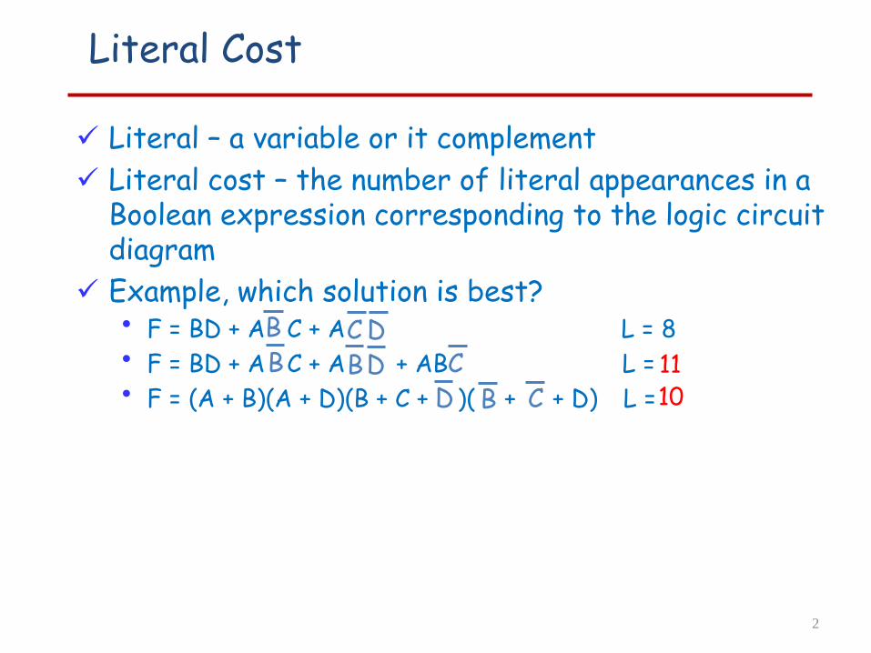
Boolean Function Optimization
Minimizing the gate input (or literal) cost of a (a set of) Boolean equation(s) reduces circuit cost.
We choose gate input cost.
Boolean Algebra and graphical techniques are tools to minimize cost criteria values.
Some important questions:• When do we stop trying to reduce the cost?
• Do we know when we have a minimum cost?
Treat optimum or near-optimum cost functionsfor two-level (SOP and POS) circuits first.
Introduce a graphical technique using Karnaugh maps (K-maps, for short)
6
Karnaugh Maps (K-map)
A K-map is a collection of squares• Each square represents a minterm• The collection of squares is a graphical representation of a
Boolean function• Adjacent squares differ in the value of one variable• Alternative algebraic expressions for the same function are
derived by recognizing patterns of squares (corresponding to cubes)
The K-map can be viewed asA reorganized version of the truth table or a
particular cube representation
7

Some Uses of K-Maps
Provide a means for:• Finding optimum
SOP and POS standard forms, and two-level AND/OR and OR/AND circuit implementations
for functions with small numbers of variables• Visualizing concepts related to manipulating Boolean
expressions• Demonstrating concepts used by computer-aided design
programs to simplify large circuits
8

9
The Boolean Space Bn
B = { 0,1}
B2 = {0,1} X {0,1} = {00, 01, 10, 11}
B0
Karnaugh Maps: Boolean Cubes:
B1
B2
B3
B4

Two Variable Maps
A 2-variable Karnaugh Map:• Note that minterm m0 and
minterm m1 are “adjacent”and differ in the value of thevariable y
• Similarly, minterm m0 and
minterm m2 differ in the
x variable.• Also, m1 and m3 differ in the x variable as well. • Finally, m2 and m3 differ in the value of the variable y
y = 0 y = 1
x = 0m0 m1
x = 1
yx yx
yx yx
10
y x
m2 m3

K-Map and Truth Tables
The K-Map is just a different form of the truth table.
Example – Two variable function:
• We choose a,b,c and d from the set {0,1} to implement a particular function, F(x,y).
Function Table K-Map
Input
Values
(x,y)
Function
Value
F(x,y)
0 0 a
0 1 b
1 0 c
1 1 d
y = 0 y = 1
x = 0 a b
x = 1 c d
11
y x

K-Map Function Representation
Example: F(x,y) = x
For function F(x,y), the two adjacent cells containing 1’s can be combined using the Minimization Theorem:
F = x y = 0 y = 1
x = 0 0 0
x = 1 1 1
xyxyx)y,x(F =+=
12

K-Map Function Representation
Example: G(x,y) = xy + xy + xy
For G(x,y), two pairs of adjacent cells containing 1’s can be combined using the Minimization Theorem:
G=x+y y = 0 y = 1
x = 0 0 1
x = 1 1 1
( ) ( ) yxyxxyyxyx)y,x(G +=+++=
Duplicate xy
13

Three Variable Maps
A three-variable K-map:
Where each minterm corresponds to the product terms:
Note that if the binary value for an index differs in one bit position, the minterms are adjacent on the K-Map
14
yz yz=00 yz=01 yz=11 yz=10
x=0
x=1
zyx zyx zyx zyx
zyx zyx zyx zyx
X
yz=00 yz=01 yz=11 yz=10
x=0 m0 m1 m3 m2
x=1 m4 m5 m7 m6
yzX

Alternative Map Labeling
Map use largely involves:• Entering values into the map, and
• Reading off product terms from the map.
Alternate labelings are useful:
yy z
z
10 2
4
3
5 67
x
0
1
00 01 11 10
x
15
y
z
x
10 2
4
3
5 67
x
y
zz
y zx

Example: Combining Squares
Example: Let
F (x, y, z) = m (2, 3, 6, 7)
Applying the Minimization Theorem three times:
Thus the four terms that form a 2 × 2 square correspond to the term "y".
y=zyyz +=
zyxzyxzyxzyx)z,y,x(F +++=
x
y
10 2
4
3
5 671 1
11
z
16
y zx
Combining Squares
By combining squares, we reduce number of literals in a product term, reducing the literal cost, thereby reducing the other two cost criteria
On a 3-variable K-Map:• One square represents a minterm with three variables
• Two adjacent squares represent a cube that is product term with two variables
• Four “adjacent” terms represent a cube that is product term with one variable
• Eight “adjacent” terms is the function of all ones (no variables) is a tautology f1=1.
17

Example Functions
By convention, we represent the minterms of F by a "1" in the map and leave the minterms of blank
Example:
F (x, y, z) = m (2, 3, 4, 5)
Example:
F (x, y, z) = m (3, 4, 6, 7)
Learn the locations of the 8 indices based on the variable order shown (x, most significantand z, least significant) on themap boundaries
y
x
10 2
4
3
5 67
1
11
1
zy
10 2
4
3
5 671 11
1
z
F
18
y zx
y zx
x

Three-Variable Maps
Reduced literal product terms for SOP standard forms correspond to cubes i.e. to rectangles on the K-maps containing cell counts that are powers of 2.
Rectangles of 2 cells represent 2 adjacent minterms; of 4 cells represent 4 minterms that form a “pairwise adjacent” ring.
19

Three-Variable Maps
Topological warps of 3-variable K-maps that show all adjacencies: Venn Diagram Cylinder
Y Z
X
13
76 5
4
2
0
20
y
z
x
10 2
4
3
5 67
x
y
zz
y zx
Three-Variable Maps
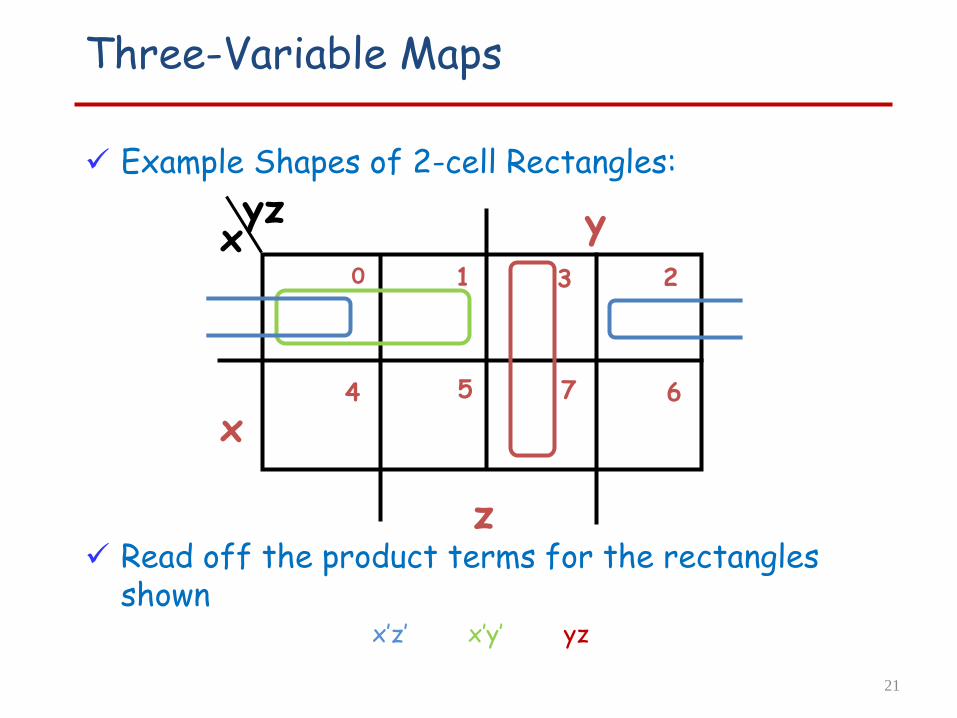
Example Shapes of 2-cell Rectangles:
Read off the product terms for the rectangles shown
x’z’ x’y’ yz
y0 1 3 2
5 64 7
x
z
21
yzx

Three-Variable Maps
Example Shapes of 4-cell Rectangles:
Read off the product terms for the rectangles shown
z’ z X’ Y’
y0 1 3 2
5 64 7
x
z
22
yzx

Three Variable Maps
y
11
x
z
1 1
1
z
z)y,F(x, = z yx+
yx
K-Maps can be used to simplify Boolean functions by a systematic methods. Terms are selected to cover the “1s”in the map.
Example: Simplify F (x, y, z) = m (1, 2, 3, 5, 7)
yzx
Three-Variable Map Simplification
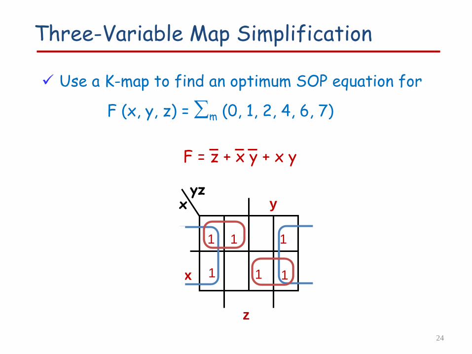
Use a K-map to find an optimum SOP equation for
F (x, y, z) = m (0, 1, 2, 4, 6, 7)
F = z + x y + x y
24
y
11
x
z
1 1 1
1
yzx

Four Variable Maps
Map and location of minterms:
8 9 1011
12 13 1415
0 1 3 2
5 64 7
X
Y
Z
W
yz=00 yz=01 yz=11 yz=10
wx=00
wx=01
wx=11
wx=10
yzWX

Four Variable Terms
Four variable maps can have rectangles corresponding to:• A single 1 = 4 variables, (i.e. Minterm)• Two 1s = 3 variables,• Four 1s = 2 variables• Eight 1s = 1 variable,• Sixteen 1s = zero variables (i.e. Constant "1")
26

Four-Variable Maps
Example Shapes of Rectangles:
8 9 1011
12 13 1415
0 1 3 2
5 64 7
X
Z
W
Y
27
yz=00 yz=01 yz=11 yz=10
wx=00
wx=01
wx=11
wx=10
yzWX

Four-Variable Maps
Example Shapes of Rectangles:
X
Y
Z
8 9 1011
12 13 1415
0 1 3 2
5 64 7
W
28
yz=00 yz=01 yz=11 yz=10
wx=00
wx=01
wx=11
wx=10
yzWX

Four-Variable Map Simplification
F = XZ + X'Z‘+W’X
)8,10,13,152,4,5,6,7,(0,Z)Y,X,F(W, mS=
29
8 9 1011
12 13 1415
0 1 3 2
5 64 7
X
Y
Z
W
1 1
1 11 1
1 1
1 1
yz=00 yz=01 yz=11 yz=10
wx=00
wx=01
wx=11
wx=10
yzWX

3,14,15
Four-Variable Map Simplification
F = W' X Y' + W' Y Z + WXY + WY'Z
)(3,4,5,7,9,1Z)Y,X,F(W, mS=
30
8 9 1011
12 13 1415
0 1 3 2
5 64 7
X
Y
Z
W
1
1 1 1
1
1 1 1
yzWX

Systematic Simplification
A Prime Implicant is a cube i.e. a product term obtained by combining the maximum possible number of adjacent squares in the map into a rectangle with the number of squares a power of 2.
A prime implicant is called an Essential Prime Implicant if it is the only prime implicant that covers (includes) one or more minterms.
Prime Implicants and Essential Prime Implicantscan be determined by inspection of a K-Map.
A set of prime implicants "covers all minterms" if, for each minterm of the function, at least one prime implicant in the set of prime implicantsincludes the minterm.
31

DB
CB
1 1
1 1
1 1
B
D
A
1 1
1 1
1
Example of Prime
Find ALL Prime Implicants
ESSENTIAL Prime Implicants
C
BD
CD
BD
Minterms covered by single prime implicant
DB
1 1
1 1
1 1
B
C
D
A
1 1
1 1
1
AD
BA
32
CDAB

Prime Implicant Practice
33
8 9 1011
12 13 1415
0 1 3 2
5 64 7
B
C
D
A
11 1
1 1
1 1 1
1 1
1
Find all prime implicants for:
F (A, B, C, D) = m (0,2,3,8,9,10,11,12,13,14,15)
Prime implicants are: A,BC, and BD
CDAB

Another Example
Find all prime implicants for:
F (A, B, C, D) = m (0,2,3,4,7,12,13,14,15)
AB, BCD, ACD, ABD, ABC, ACD, BCD
34m= AB+ACD+ACD+ABC c= m+ABD+BCD+BCD
8 9 1011
12 13 1415
0 1 3 2
5 64 7
B
C
D
A
11 1
1
1 1 1
1
1
CDAB

Find all prime implicates for:
F=(w+y+z) (w’+x’+y) (x+y) (w+x+y’) (w+x’+z) (w’+x+z)
K-Maps, implicates
35
8 9 1011
12 13 1415
0 1 3 2
5 64 7
X
Z
W
0
0
0 0
0 0
0 0
0
0
0
m= (w+x)(w’+y)(w+z)(x+z)
yz=00 yz=01 yz=11 yz=10
wx=00
wx=01
wx=11
wx=10
Y
c= m(y+z)
YZWX

Five Variable or More K-Maps
For five variable problems, we use two adjacent K-maps. It becomes harder to visualize adjacent minterms for selecting PIs. You can extend the problem to six variables by using four K-Maps.
X
Y
Z
W
V = 0
X
Z
W
V = 1Y
36
YZWX
YZWX

Find all prime implicants for:
G(v,w,x,y,z)=m(0,1,2,4,5,6,7,8,10,16,17,18,20,21,24,25,26,27,29)
Five Variable K-Maps
37
1111
111
1
1
11
1 1111
1
1
1X
Y
Z
W
V = 0
X
Z
W
V = 1Y
m= w’y’+x’z’+v’w’x+vy’z+vwx’ c= m+v’w’z’
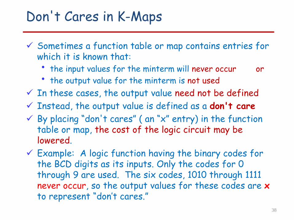
Sometimes a function table or map contains entries for which it is known that:
• the input values for the minterm will never occur or
• the output value for the minterm is not used
In these cases, the output value need not be defined
Instead, the output value is defined as a don't care
By placing “don't cares” ( an “x” entry) in the function table or map, the cost of the logic circuit may be lowered.
Example: A logic function having the binary codes for the BCD digits as its inputs. Only the codes for 0 through 9 are used. The six codes, 1010 through 1111 never occur, so the output values for these codes are xto represent “don’t cares.”
Don't Cares in K-Maps
38

39
Incompletely Specified Functions
F = (f, d, r) : Bn {0, 1, x}where x represents “don’t care”.
• f = onset function - f(x)=1 F (x)=1 • r = offset function - r(x)=1 F (x)=0 • d = don’t care function - d(x)=1 F (x)=*
(f,d,r) forms a partition of Bn. i.e.• f + d + r = Bn
• fd = fr = dr = (pairwise disjoint)

40
Example:Logic Minimization
Consider F (a,b,c)=(f,d,r), where f={abc, abc, abc} and d ={abc, abc}, and the sequence of covers illustrated below:
F1= abc + abc+ abc
abc is redundanta is primeF
3= a+abc
Expand abc bc
Expand abca
F2= a+abc + abc
F4= a+bc
Off
On
Don’t care
a
c
b

Example: BCD “5 or More”
In the map below gives a function F1(w,x,y,z) which is defined as "5 or more" over BCD inputs. With the don't cares used for the 6 non-BCD combinations:
z
w
0 1 3 2
4 5 7 6
12 13 15 14
8 9 11 10
1
1
11
1
X X X
X X
X
0 0 0 0
0
x
y
yxwyxwzxwz) y,x,F1(w, ++=
41
F2 (w,x,y,z) = w + x z + x yG = 7
This is much lower in cost than F1 where the “don't cares” were treated as "0s" having G = 12For this particular function, cost G for the POS solution for F1(w,x,y,z) is not changed by using the don't cares.
F3 (w,x,y,z) = (w + x) (w + y + z) G = 7

Product of Sums Example
Find the optimum POS solution:
F (A,B,C,D)=m(3,9,11,12,13,14,15) +m (1,4,6)• Hint: Use F‘ and complement it to get the result.
F = A B+B' D
F = (B + D)(A + B') 42
B
C
D
A
x
x
x
1
11
1
1 11B
D
A
C
x
xx 11
1 1
1 1
F' = B' D' + A' B
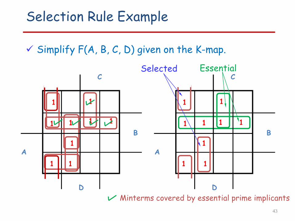
Selection Rule Example
Simplify F(A, B, C, D) given on the K-map.
1
1
1
1 1
1
1
B
D
A
C
1
1
1
1
1
1 1
1
1
B
D
A
C
1
1
Essential
Minterms covered by essential prime implicants
Selected
43

Selection Rule Example with Don't Cares
Simplify F(A, B, C, D) given on the K-map.
Selected
Minterms covered by essential prime implicants
1
1
x
x
x x
1
B
D
A
C
1
1 1
1
x
x
x x
1
B
D
A
C
1
1
Essential
44

Combinational Circuits
A combinational logic circuit has:• A set of m Boolean inputs,
• A set of n Boolean outputs, and
• n switching functions, each mapping the 2m input combinations to an output such that the current output depends only on the current input values
A block diagram:
m Boolean Inputs n Boolean Outputs
COMBINATORIAL
LOGIC
CIRCUIT

Design Procedure
Specification• Write a specification for the circuit
Formulation• Derive a truth table or initial Boolean equations that
define the required relationships between the inputs and outputs
Optimization• Apply 2-level and multiple-level optimization
• Draw a logic diagram for the resulting circuit using ANDs, ORs, and inverters
Technology Mapping• Map the logic diagram to the implementation technology
selected
Verification• Verify the correctness of the final design
Design Example BCD to Excess-3 code converter
Specification • BCD to Excess-3 code converter
Transforms BCD code for the decimal digits to Excess-3 code for the decimal digits
• BCD code words for digits 0 through 9 4-bit patterns 0000 to 1001, respectively
• Excess-3 code words for digits 0 through 9 4-bit patterns consisting of 3 (binary 0011) added to each BCD
code word
• Implementation: multiple-level circuit NAND gates (including inverters)

Specification of BCD-to-Excess3
Inputs: a BCD input, A,B,C,D with A as the most significant bit and D as the least significant bit.
Outputs: an Excess-3 output W,X,Y,Z that corresponds to the BCD input.
Internal operation – circuit to do the conversion in combinational logic.
48
BCD to Excess-3converter
W X Y Z
A B C D
Formulation of BCD-to-Excess-3
Excess-3 code is easily formed by adding a binary 3 to the binary or BCD for the digit.
There are 16 possible inputs for both BCD and Excess-3.
It can be assumed that only valid BCD inputs will appear so the six combinations not used can be treated as don’t cares.
49

BCD-to-Excess-3 Code converter
50

Expressions for W X Y Z
W(A,B,C,D) = Σm(5,6,7,8,9) + d(10,11,12,13,14,15)
X(A,B,C,D) = Σm(1,2,3,4,9) + d(10,11,12,13,14,15)
Y(A,B,C,D) = Σm(0,3,4,7,8) + d(10,11,12,13,14,15)
Z(A,B,C,D) = Σm(0,2,4,6,8) + d(10,11,12,13,14,15)
51

Optimization – BCD-to-Excess-3
Lay out K-maps for each output, W X Y Z
52
Σm (5,6,7,8,9)
W = A + BC + BD

Optimization – BCD-to-Excess-3
Lay out K-maps for each output, W X Y Z
53
Σm (1,2,3,4,9)
X = BC’D’+B’C+B’D
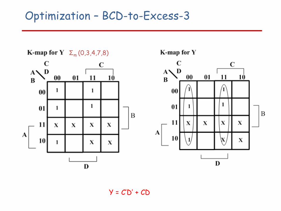
Optimization – BCD-to-Excess-3
Y = C’D’ + CD
Σm (0,3,4,7,8)
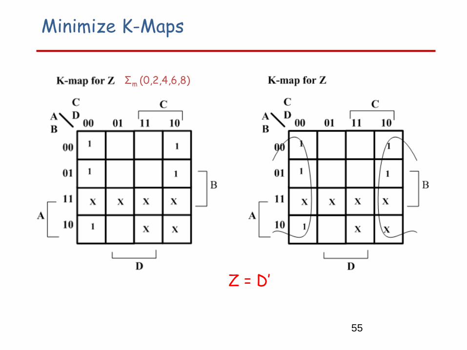
Minimize K-Maps
Z minimization
Z = D’
55
Σm (0,2,4,6,8)

Two level versus multi-level circuit implementation
Have equations• W = A + BC + BD • X = B’C + B’D + BC’D’ • Y = CD + C’D’• Z = D’
Call T= C+D, then T’ = (C+D)’ = C’D’
• W = A + BT• X = B’T + BT’• Y = CD + T’• Z = D’
56
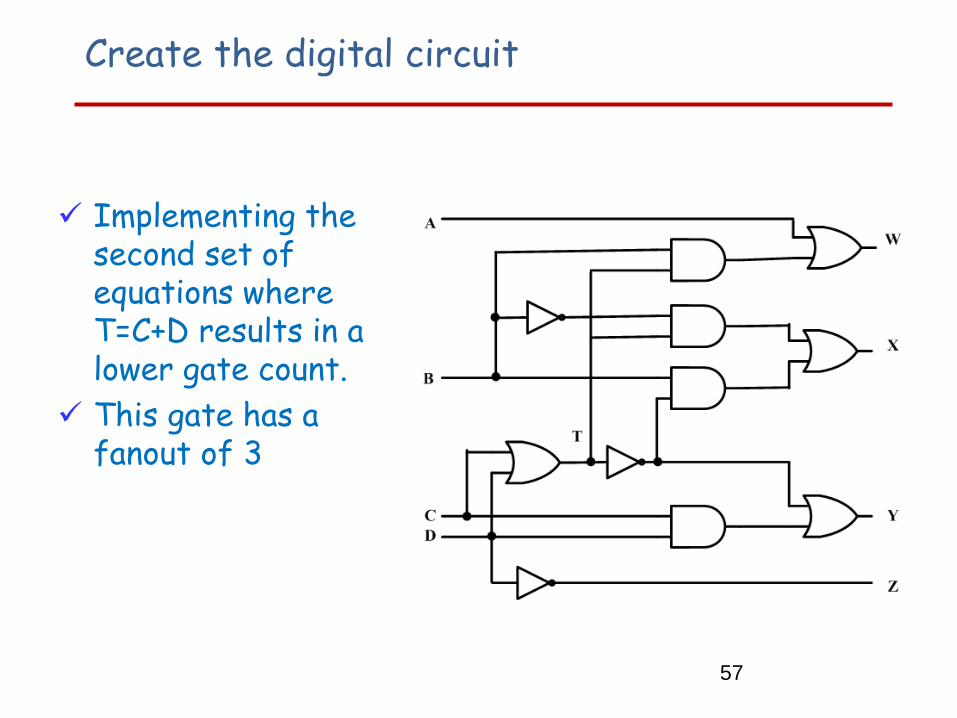
Create the digital circuit
Implementing the second set of equations where T=C+D results in a lower gate count.
This gate has a fanout of 3
57