Chapter 1 · Orthographic projection technique can produce either 1. Multiview drawing . that each...
89
Chapter 1 Overview of an Engineering Drawing
Transcript of Chapter 1 · Orthographic projection technique can produce either 1. Multiview drawing . that each...
Chapter 1
Overview of an Engineering Drawing
TOPICS
Drawing standards
Projection methods
Orthographic projection
Graphics language
Engineering drawing
TOPICS
Traditional Drawing Tools
Freehand Sketching
Lettering
GRAPHICS LANGUAGE
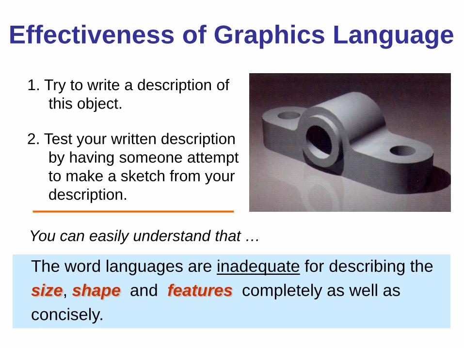
1. Try to write a description of this object.
2. Test your written description by having someone attempt to make a sketch from your description.
Effectiveness of Graphics Language
The word languages are inadequate for describing the size, shape and features completely as well as concisely.
You can easily understand that …
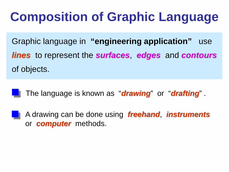
Graphic language in “engineering application” use
lines to represent the surfaces, edges and contours of objects.
A drawing can be done using freehand, instruments or computer methods.
Composition of Graphic Language
The language is known as “drawing” or “drafting” .
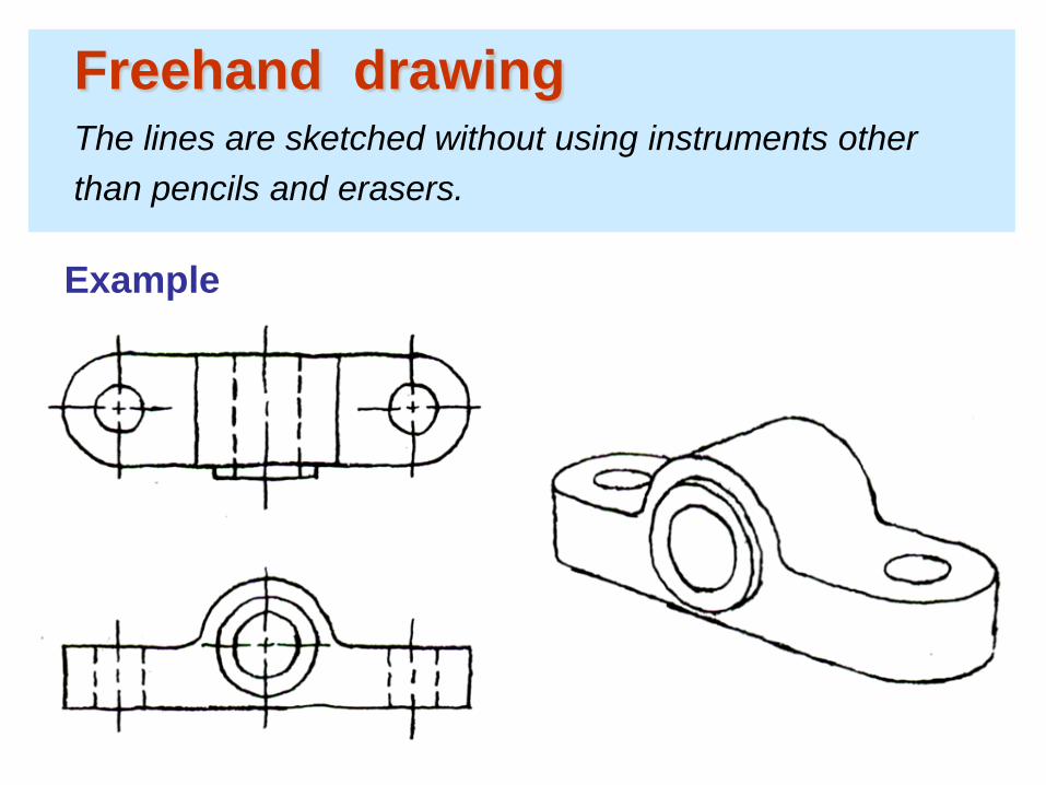
Freehand drawing The lines are sketched without using instruments other than pencils and erasers.
Example
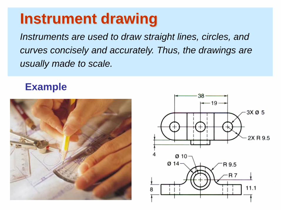
Instrument drawing Instruments are used to draw straight lines, circles, and curves concisely and accurately. Thus, the drawings are usually made to scale.
Example
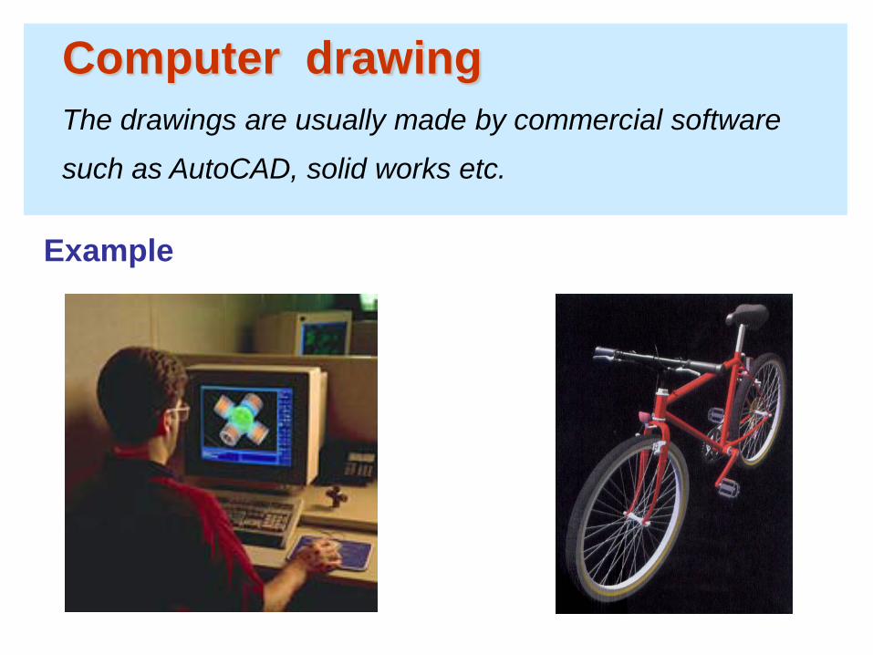
Computer drawing The drawings are usually made by commercial software
such as AutoCAD, solid works etc.
Example
Popular CAD programs include AutoCAD, Inventor, SolidWorks, and ProE.
CAD Software
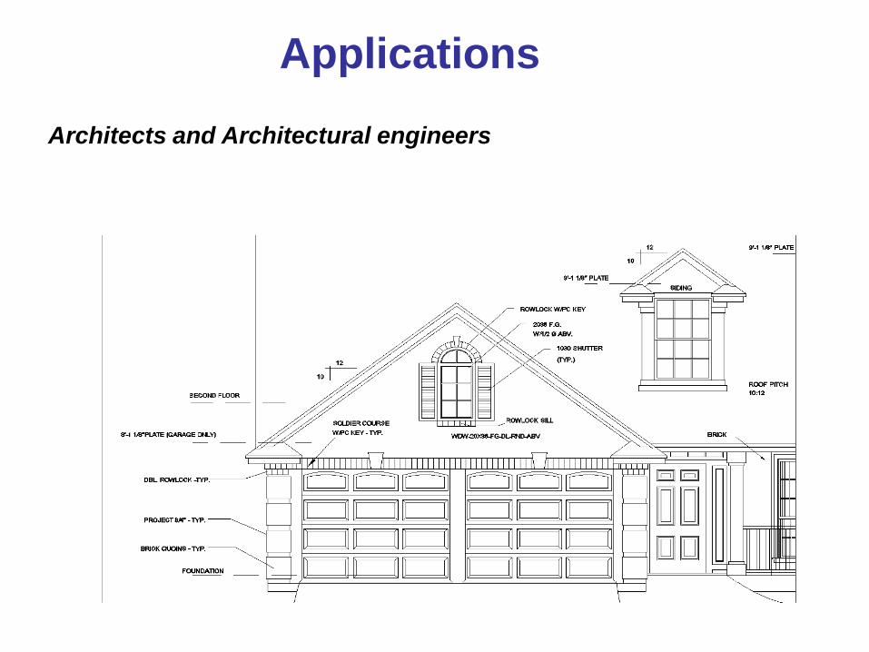
Applications Architects and Architectural engineers
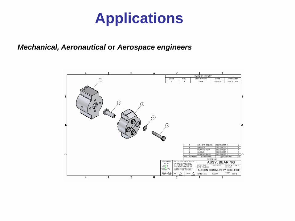
Mechanical, Aeronautical or Aerospace engineers
Applications
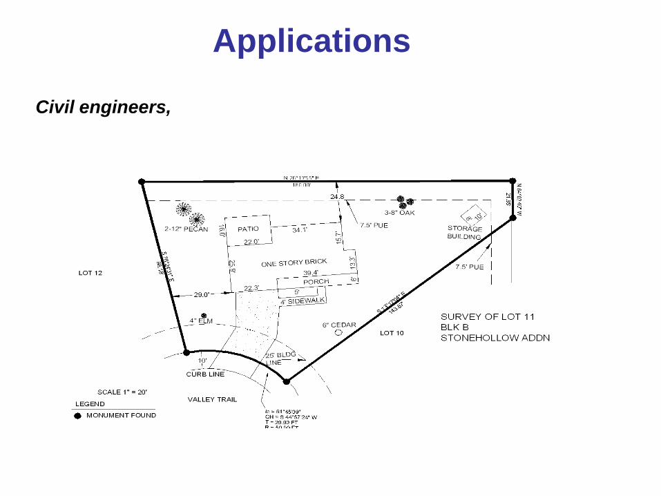
Civil engineers,
Applications
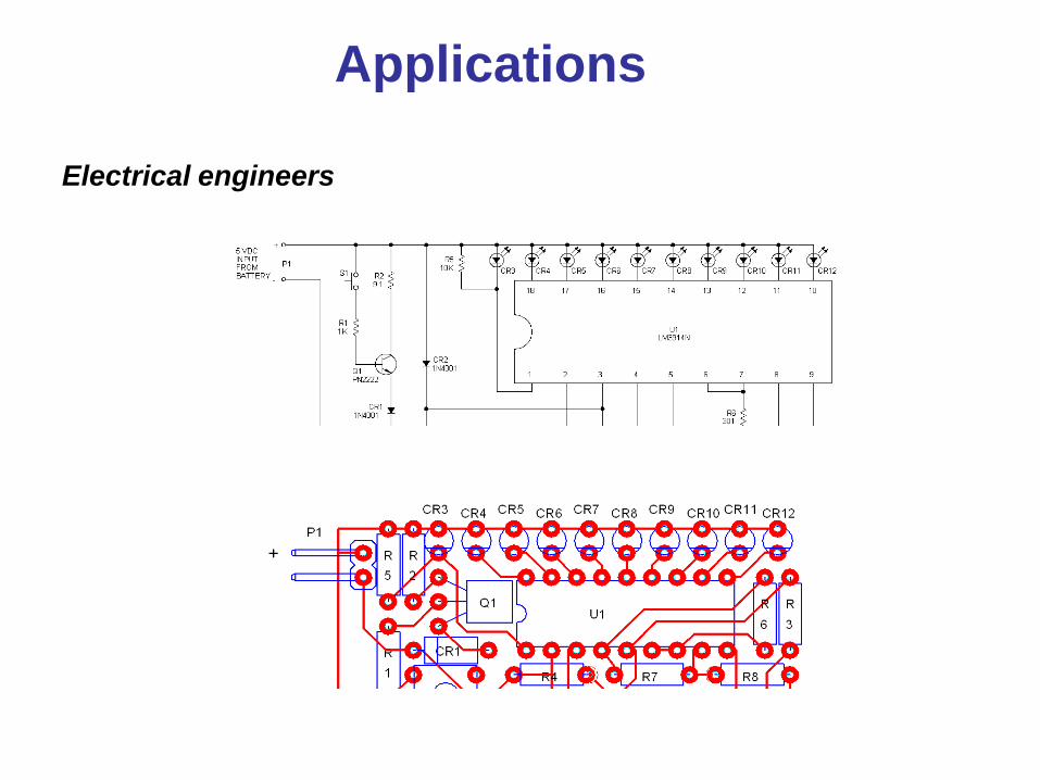
Electrical engineers
Applications

Pipeline engineers
Applications
Engineering Drawing
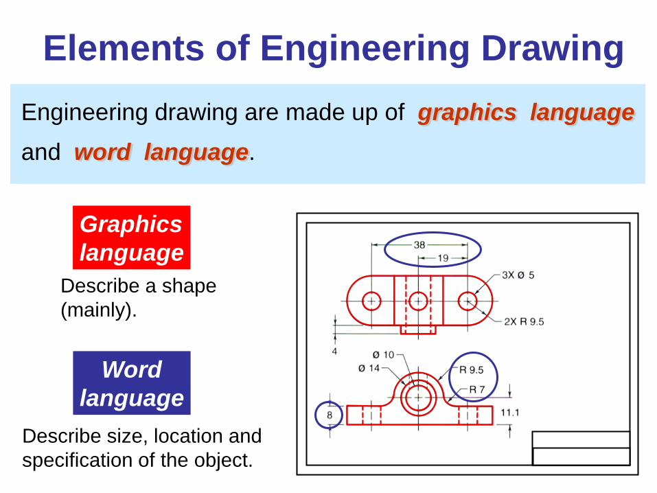
Elements of Engineering Drawing Engineering drawing are made up of graphics language and word language.
Graphics language
Describe a shape (mainly).
Word language
Describe size, location and specification of the object.
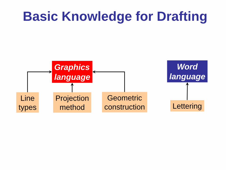
Basic Knowledge for Drafting
Graphics language
Word language
Line types
Geometric construction Lettering
Projection method
PROJECTION METHOD
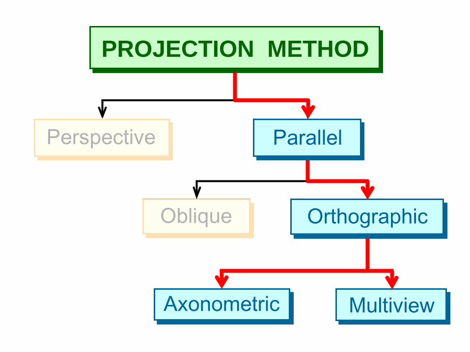
PROJECTION METHOD
Perspective
Oblique Orthographic
Axonometric Multiview
Parallel
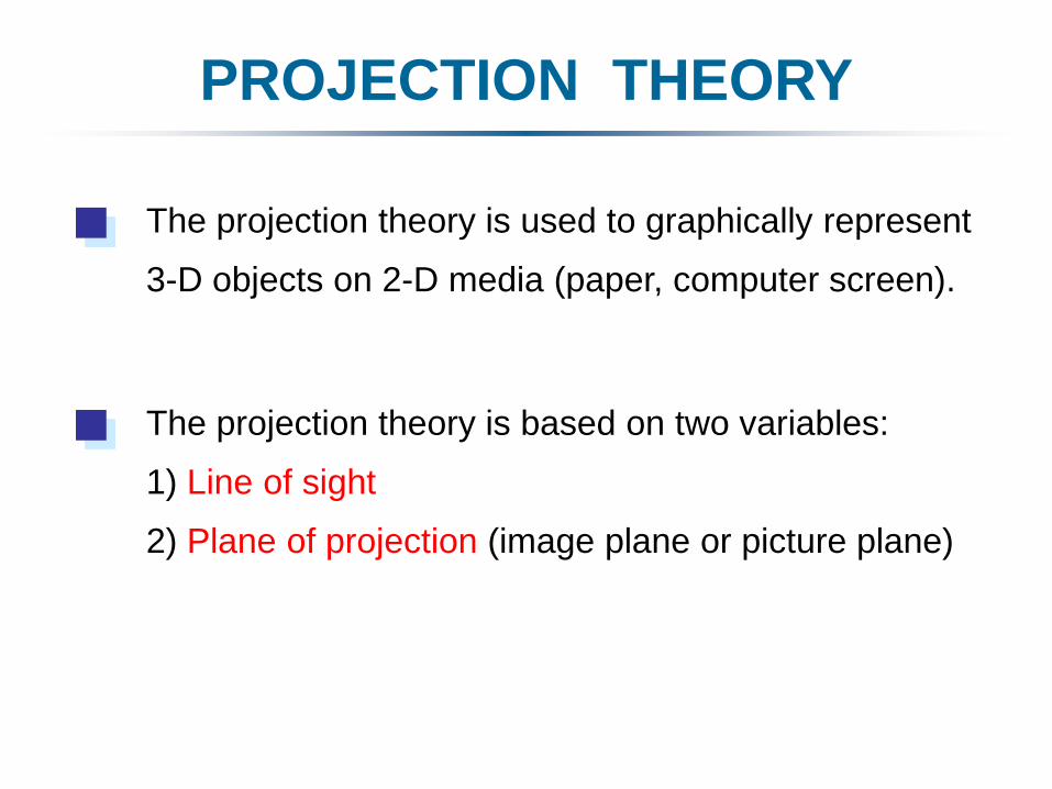
PROJECTION THEORY
The projection theory is based on two variables:
1) Line of sight
2) Plane of projection (image plane or picture plane)
The projection theory is used to graphically represent
3-D objects on 2-D media (paper, computer screen).
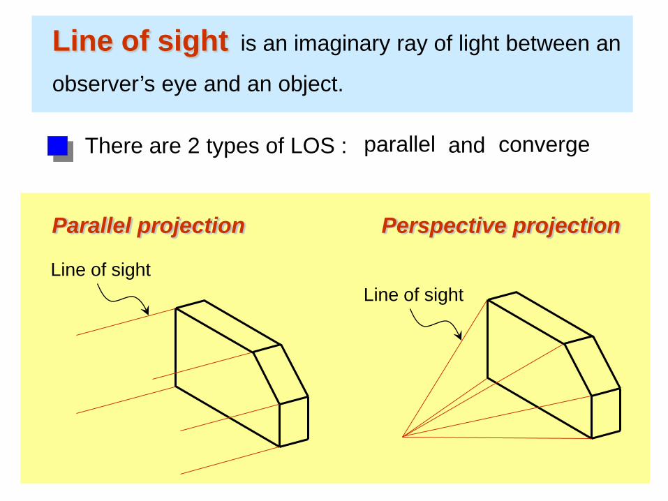
Line of sight is an imaginary ray of light between an
observer’s eye and an object.
Line of sight
Parallel projection
Line of sight
Perspective projection
There are 2 types of LOS : parallel converge and
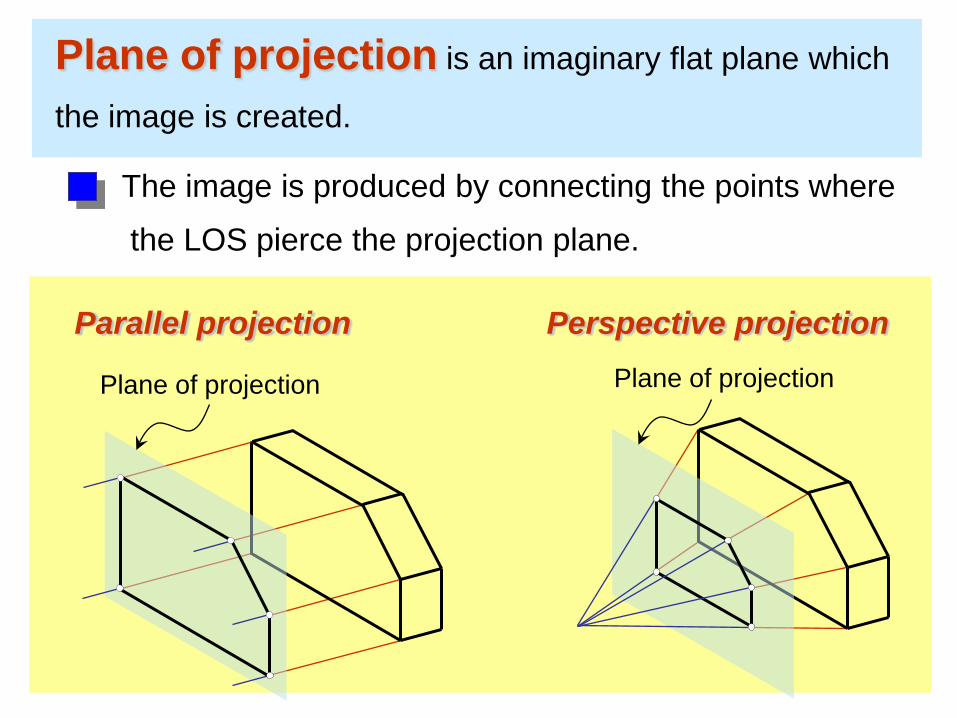
Plane of projection is an imaginary flat plane which
the image is created.
The image is produced by connecting the points where
the LOS pierce the projection plane.
Parallel projection Perspective projection
Plane of projection Plane of projection
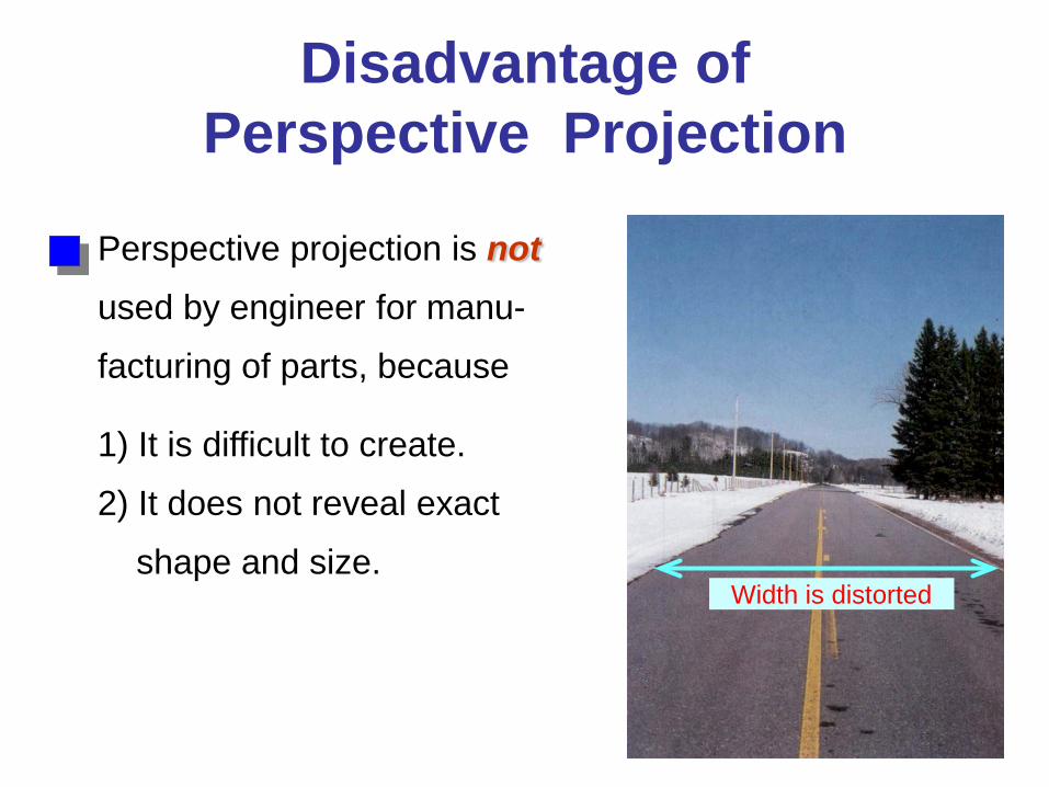
Disadvantage of Perspective Projection
Perspective projection is not used by engineer for manu-
facturing of parts, because
1) It is difficult to create.
2) It does not reveal exact
shape and size. Width is distorted
Orthographic Projection
5
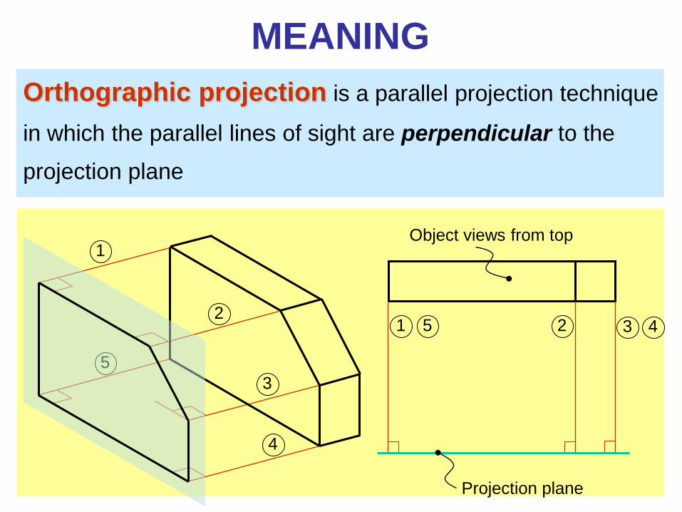
Orthographic projection is a parallel projection technique
in which the parallel lines of sight are perpendicular to the
projection plane
MEANING
Object views from top
Projection plane
1
2
3
4
5 1 2 3 4
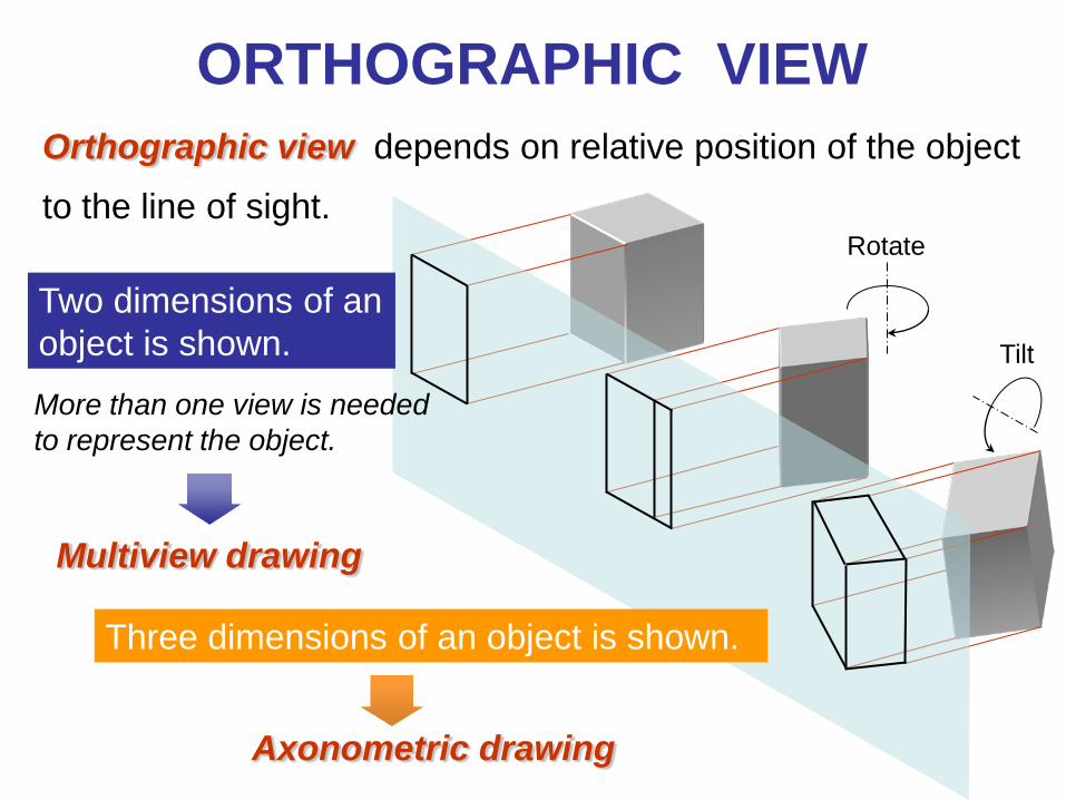
ORTHOGRAPHIC VIEW Orthographic view depends on relative position of the object
to the line of sight.
Two dimensions of an object is shown.
Three dimensions of an object is shown.
Rotate
Tilt
More than one view is needed to represent the object.
Multiview drawing
Axonometric drawing
Orthographic projection technique can produce either
1. Multiview drawing that each view show an object in two dimensions.
2. Axonometric drawing that show all three dimensions of an object in one view. Both drawing types are used in technical drawing for
communication.
NOTES
ORTHOGRAPHIC VIEW
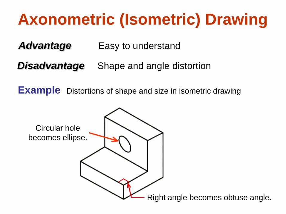
Axonometric (Isometric) Drawing Easy to understand
Right angle becomes obtuse angle.
Circular hole becomes ellipse.
Distortions of shape and size in isometric drawing
Advantage
Disadvantage Shape and angle distortion
Example
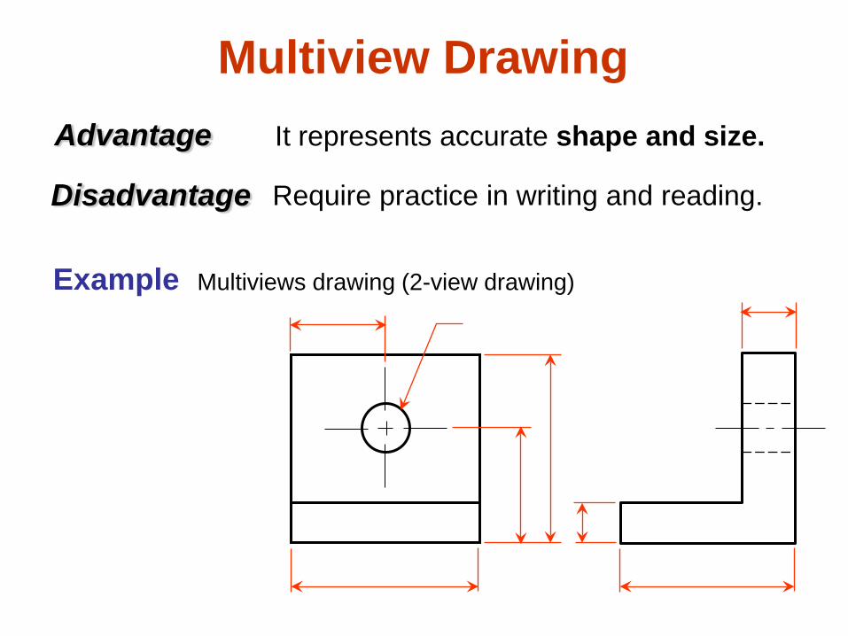
Multiview Drawing It represents accurate shape and size. Advantage
Disadvantage Require practice in writing and reading.
Multiviews drawing (2-view drawing) Example
Drawing Standard
Introduction
Standards are set of rules that govern how technical
drawings are represented.
Drawing standards are used so that drawings convey
the same meaning to everyone who reads them.
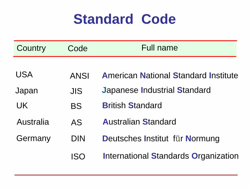
ISO International Standards Organization
Standard Code
ANSI American National Standard Institute USA
JIS Japanese Industrial Standard Japan
BS British Standard UK
AS Australian Standard Australia
Deutsches Institut für Normung DIN Germany
Country Code Full name
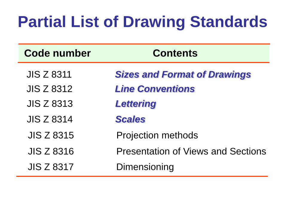
Partial List of Drawing Standards
JIS Z 8311 Sizes and Format of Drawings JIS Z 8312 Line Conventions JIS Z 8313 Lettering JIS Z 8314 Scales JIS Z 8315 Projection methods
JIS Z 8316 Presentation of Views and Sections JIS Z 8317 Dimensioning
Code number Contents
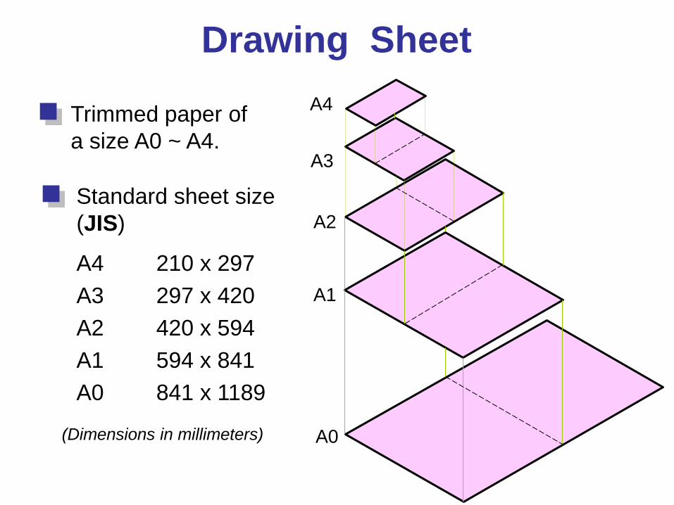
Drawing Sheet
Trimmed paper of a size A0 ~ A4.
Standard sheet size (JIS)
A4 210 x 297 A3 297 x 420 A2 420 x 594 A1 594 x 841 A0 841 x 1189
A4
A3
A2
A1
A0 (Dimensions in millimeters)
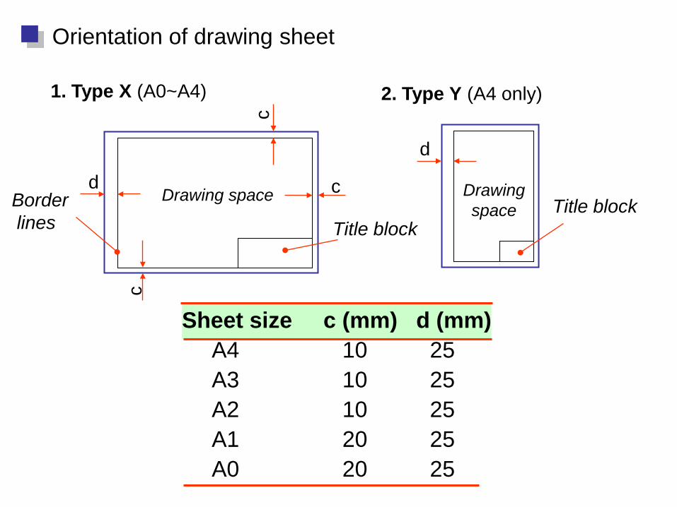
Drawing space Drawing space
Title block
d
d
c
c
c Border lines
1. Type X (A0~A4) 2. Type Y (A4 only)
Orientation of drawing sheet
Title block
Sheet size c (mm) d (mm) A4 10 25 A3 10 25 A2 10 25 A1 20 25 A0 20 25
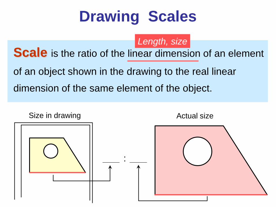
Drawing Scales
Scale is the ratio of the linear dimension of an element
of an object shown in the drawing to the real linear
dimension of the same element of the object.
Size in drawing Actual size
Length, size
:
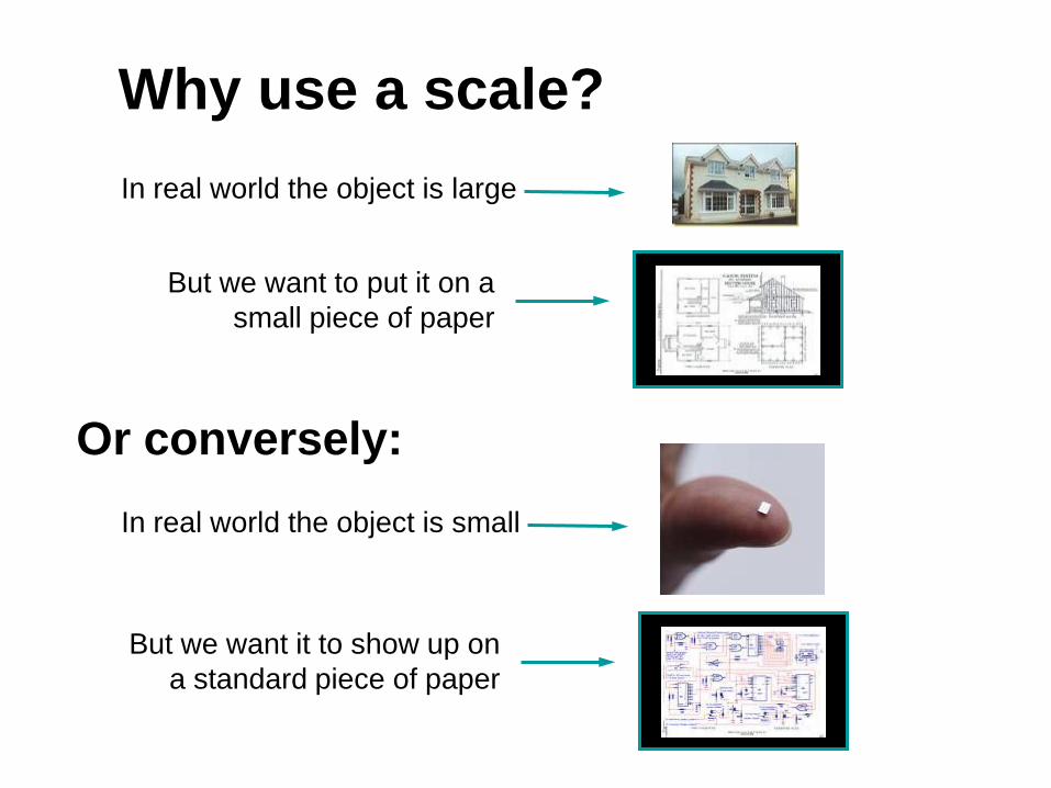
Or conversely: In real world the object is small
But we want it to show up on a standard piece of paper
But we want to put it on a small piece of paper
In real world the object is large
Why use a scale?
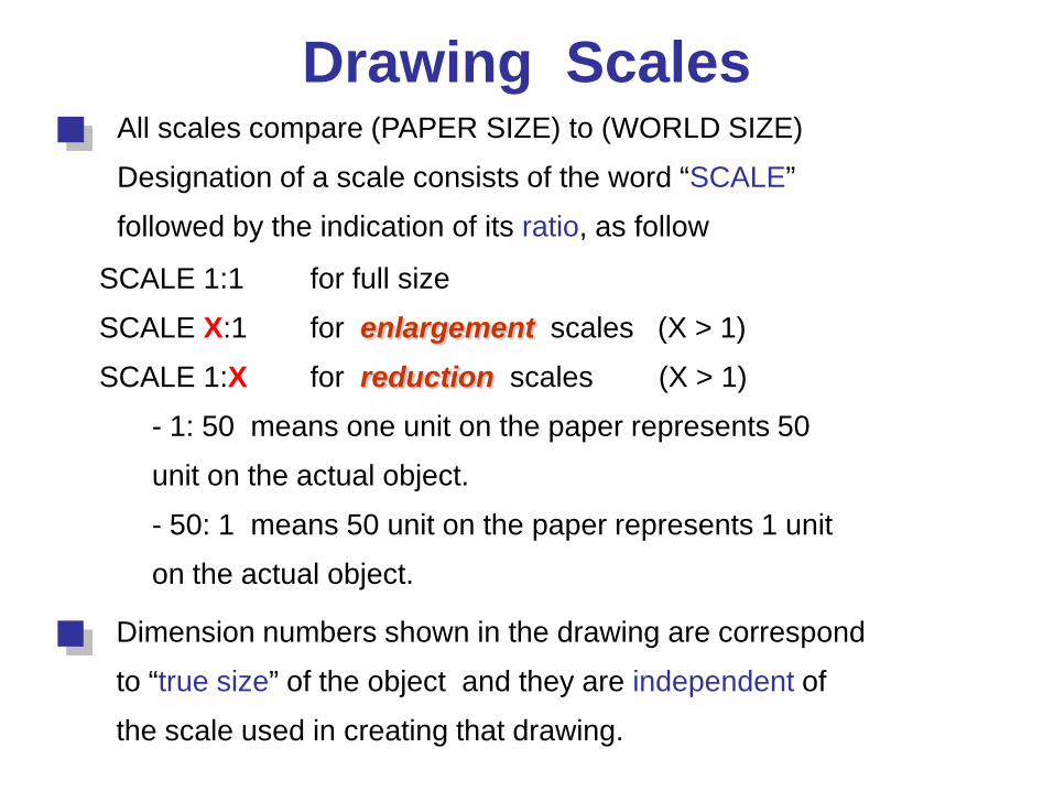
Drawing Scales All scales compare (PAPER SIZE) to (WORLD SIZE)
Designation of a scale consists of the word “SCALE”
followed by the indication of its ratio, as follow
SCALE 1:1 for full size
SCALE X:1 for enlargement scales (X > 1)
SCALE 1:X for reduction scales (X > 1)
- 1: 50 means one unit on the paper represents 50
unit on the actual object.
- 50: 1 means 50 unit on the paper represents 1 unit
on the actual object.
Dimension numbers shown in the drawing are correspond
to “true size” of the object and they are independent of
the scale used in creating that drawing.
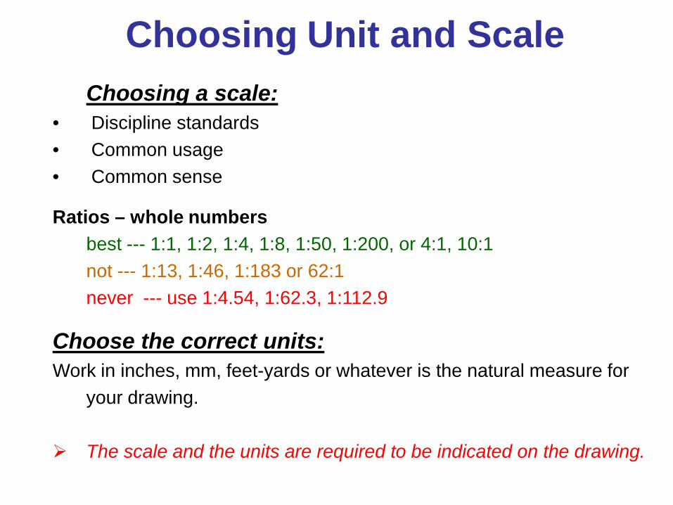
Choosing Unit and Scale Choosing a scale:
• Discipline standards • Common usage • Common sense
Ratios – whole numbers best --- 1:1, 1:2, 1:4, 1:8, 1:50, 1:200, or 4:1, 10:1 not --- 1:13, 1:46, 1:183 or 62:1 never --- use 1:4.54, 1:62.3, 1:112.9
Choose the correct units: Work in inches, mm, feet-yards or whatever is the natural measure for
your drawing. The scale and the units are required to be indicated on the drawing.
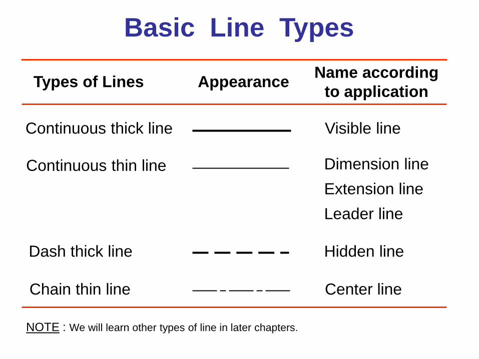
Basic Line Types
Types of Lines Appearance Name according to application
Continuous thick line Visible line
Continuous thin line Dimension line Extension line Leader line
Dash thick line Hidden line
Chain thin line Center line
NOTE : We will learn other types of line in later chapters.
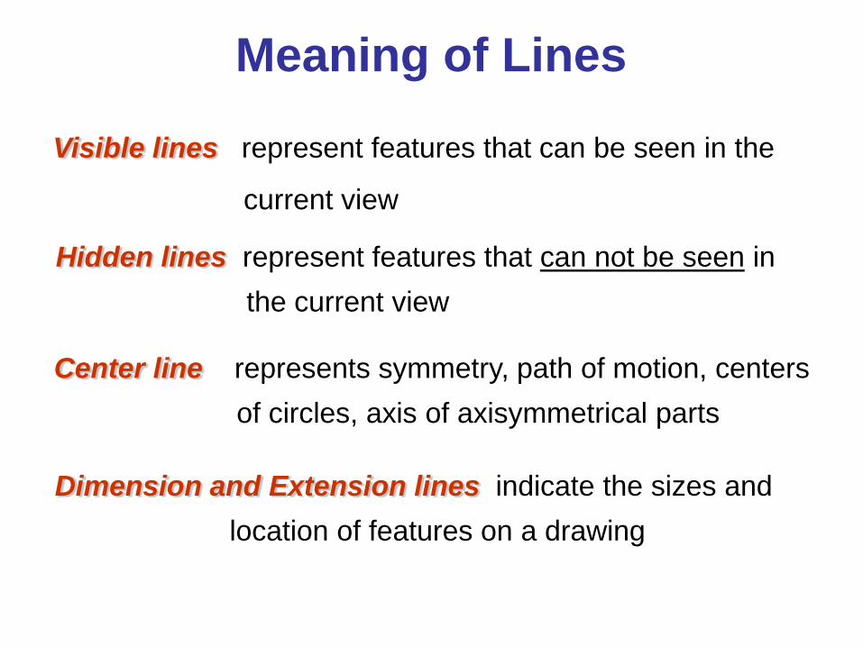
Visible lines represent features that can be seen in the
current view
Meaning of Lines
Hidden lines represent features that can not be seen in the current view
Center line represents symmetry, path of motion, centers of circles, axis of axisymmetrical parts
Dimension and Extension lines indicate the sizes and location of features on a drawing
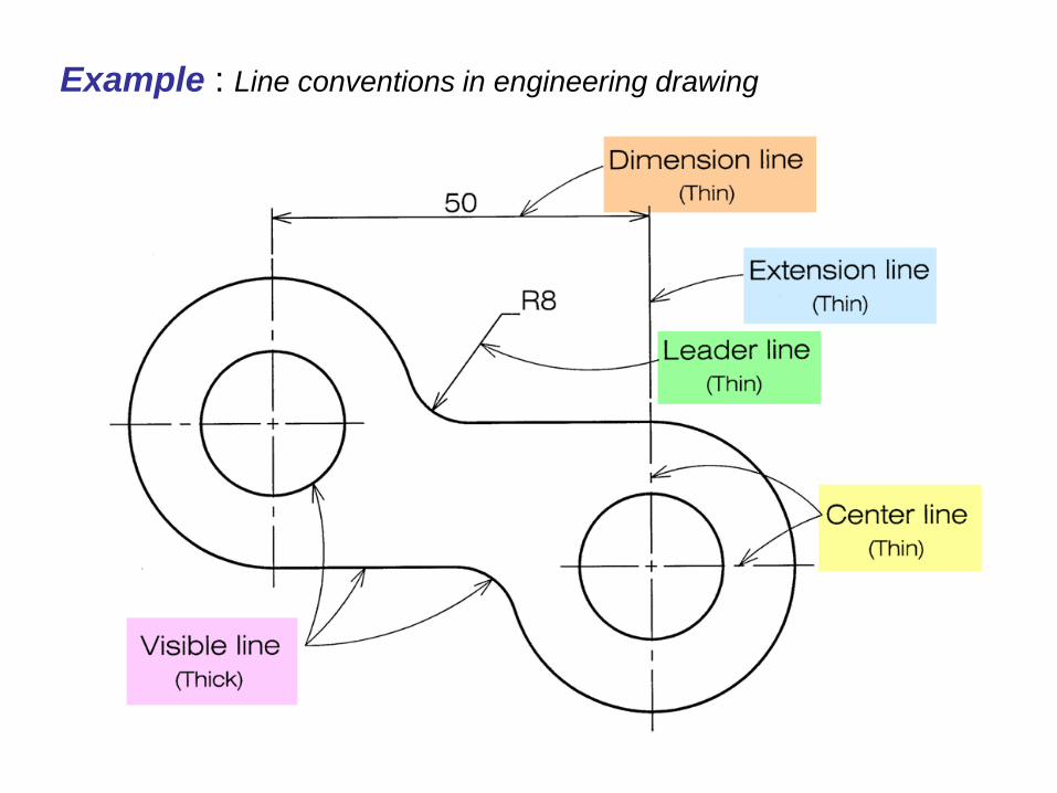
Example : Line conventions in engineering drawing
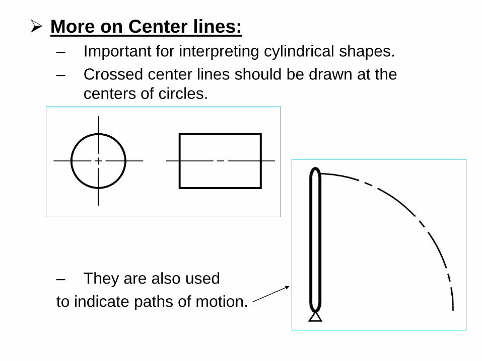
More on Center lines: – Important for interpreting cylindrical shapes. – Crossed center lines should be drawn at the
centers of circles.
– They are also used to indicate paths of motion.
Traditional Drawing Tools
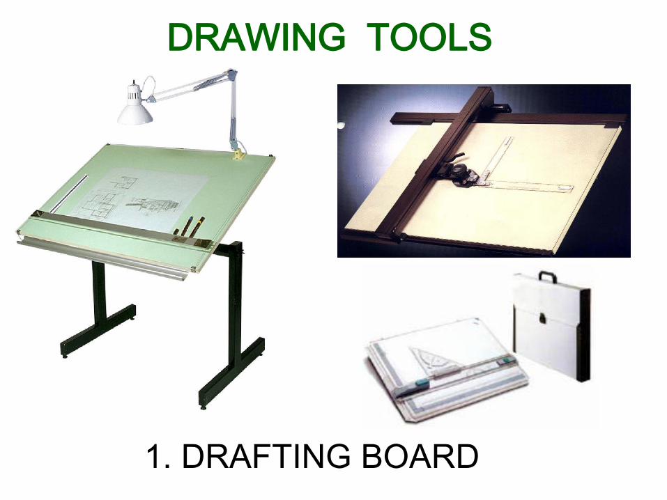
DRAWING TOOLS
1. DRAFTING BOARD
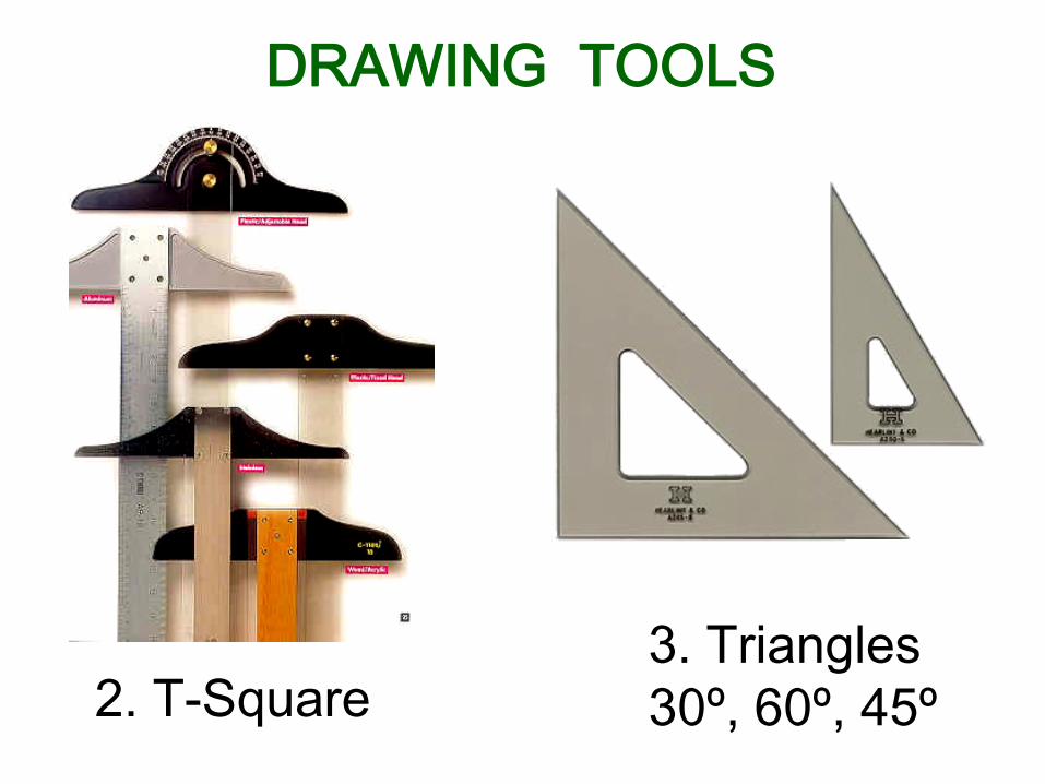
2. T-Square 3. Triangles 30º, 60º, 45º
DRAWING TOOLS
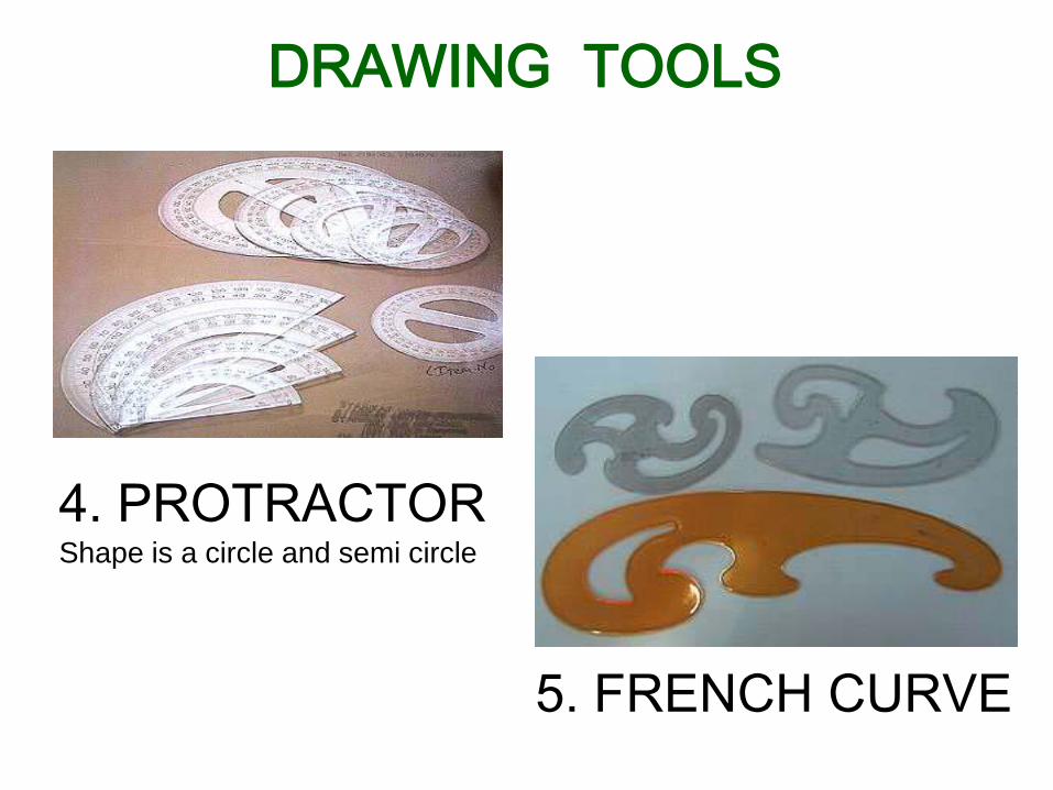
DRAWING TOOLS
4. PROTRACTOR Shape is a circle and semi circle
5. FRENCH CURVE
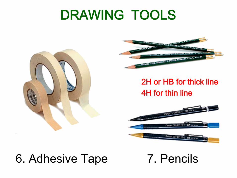
6. Adhesive Tape 7. Pencils
2H or HB for thick line 4H for thin line
DRAWING TOOLS
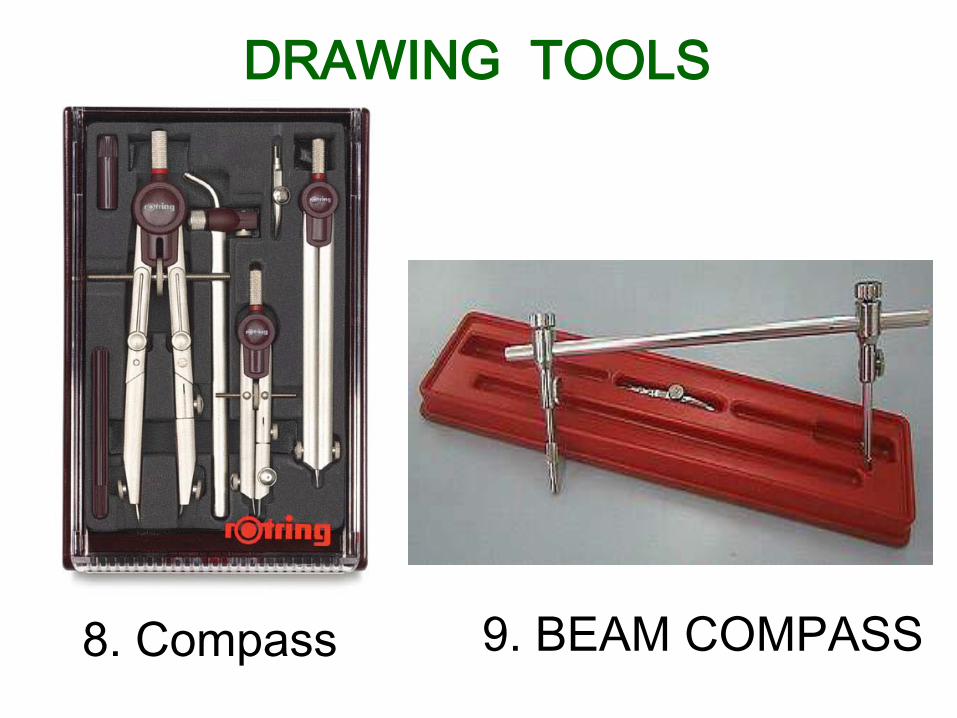
9. BEAM COMPASS 8. Compass
DRAWING TOOLS
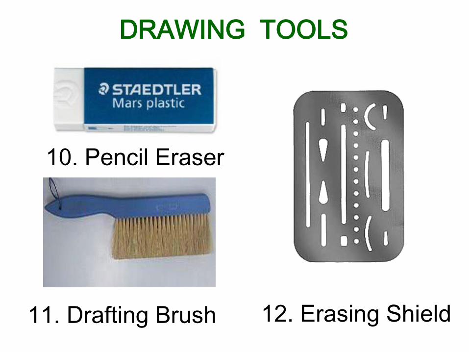
10. Pencil Eraser
12. Erasing Shield
DRAWING TOOLS
11. Drafting Brush
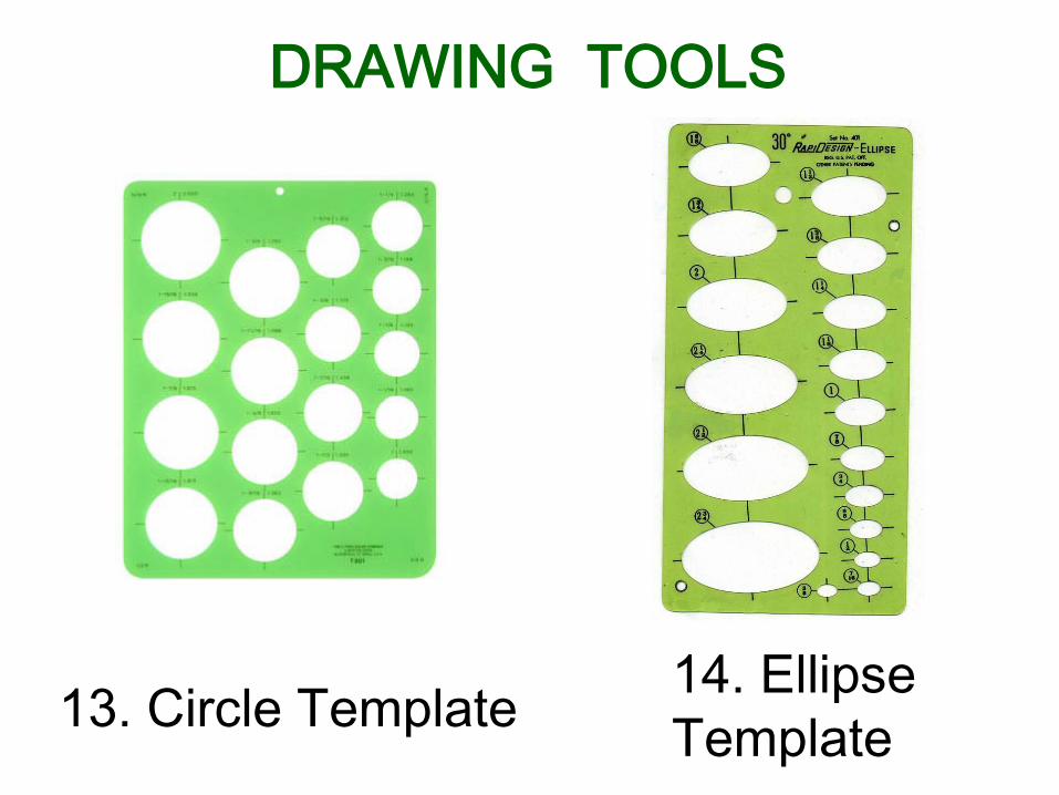
13. Circle Template 14. Ellipse Template
DRAWING TOOLS
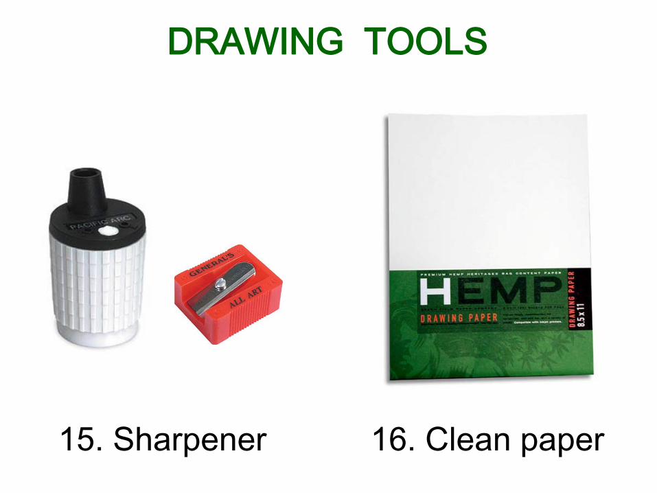
15. Sharpener 16. Clean paper
DRAWING TOOLS
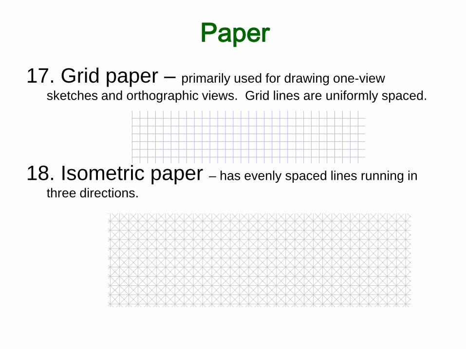
Paper 17. Grid paper – primarily used for drawing one-view
sketches and orthographic views. Grid lines are uniformly spaced.
18. Isometric paper – has evenly spaced lines running in
three directions.
ABCDEFGHIJKLMNOPQRSTUVWXYZABCDEFGHIJKLMNOPQRSTUVWXYZABCDEF
ABCDEFGHIJKLMNOPQRSTUVWXYZABCDEFGHIJKLMNOPQRSTUVWXYZABCDEF
Lettering
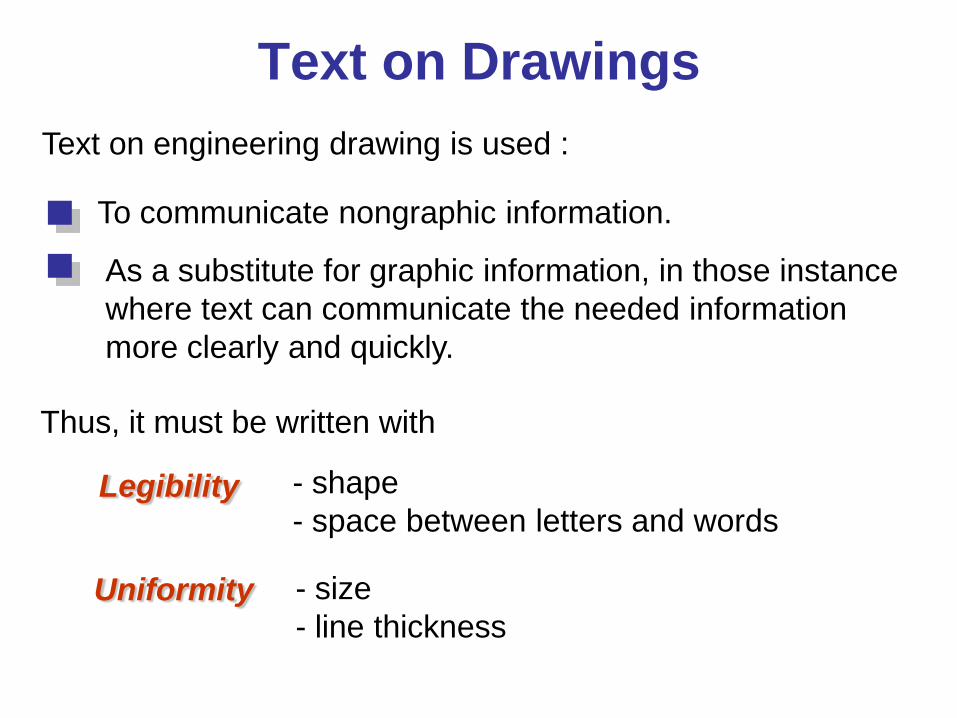
Text on Drawings Text on engineering drawing is used :
To communicate nongraphic information.
As a substitute for graphic information, in those instance where text can communicate the needed information more clearly and quickly.
Uniformity - size - line thickness
Legibility - shape - space between letters and words
Thus, it must be written with
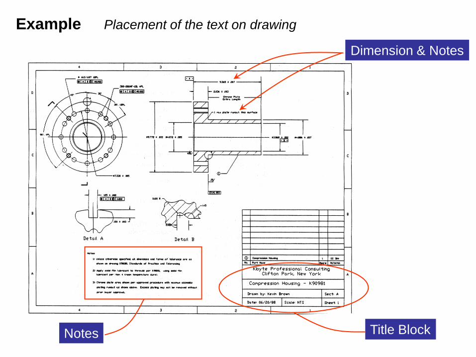
Example Placement of the text on drawing
Dimension & Notes
Notes Title Block
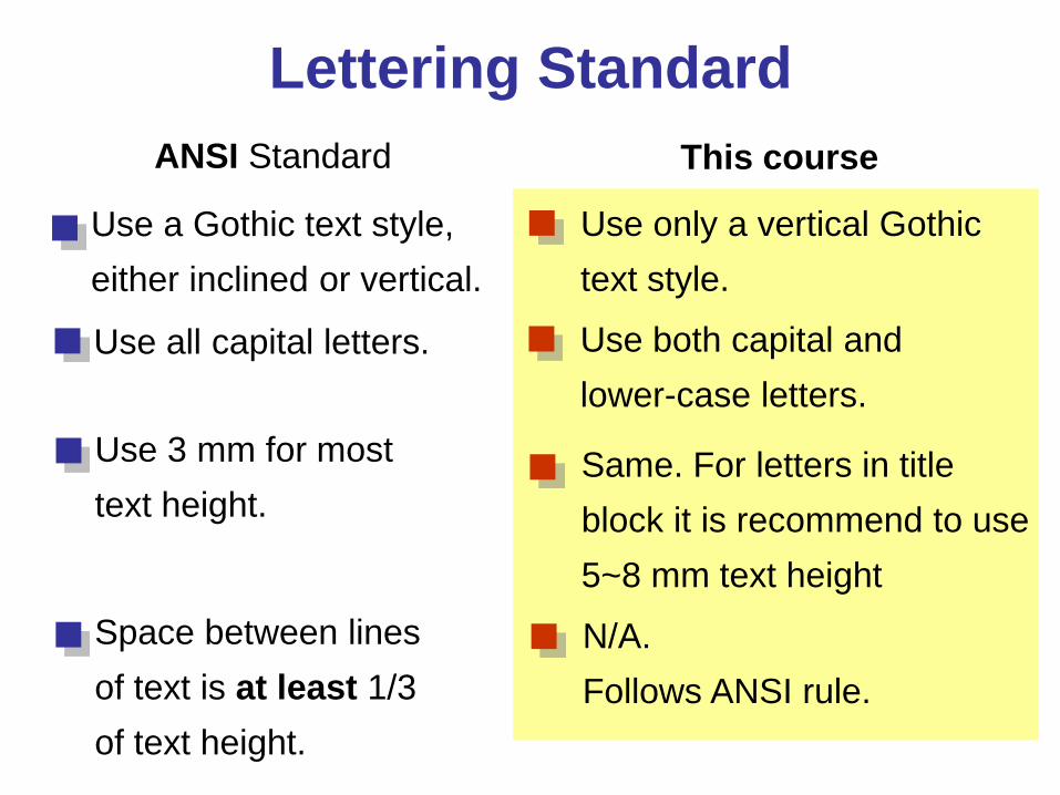
Lettering Standard ANSI Standard This course
Use a Gothic text style, either inclined or vertical.
Use all capital letters.
Use 3 mm for most text height.
Space between lines of text is at least 1/3 of text height.
Use only a vertical Gothic text style.
Use both capital and lower-case letters.
Same. For letters in title block it is recommend to use 5~8 mm text height
N/A. Follows ANSI rule.
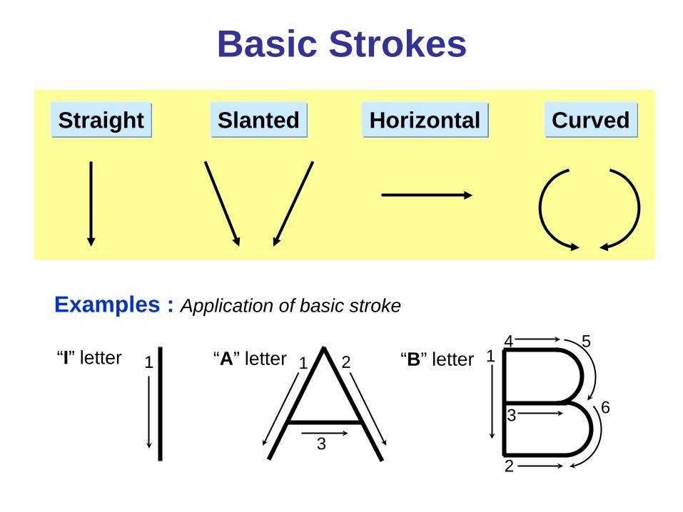
Basic Strokes
Straight Slanted Curved Horizontal
1 1 2
3
Examples : Application of basic stroke
“I” letter “A” letter 1
2
3
4 5
6
“B” letter
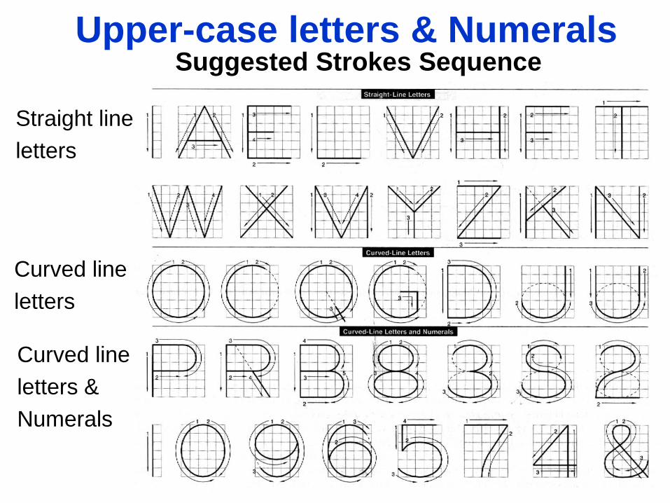
Suggested Strokes Sequence
Straight line letters
Curved line letters
Curved line letters & Numerals
Upper-case letters & Numerals
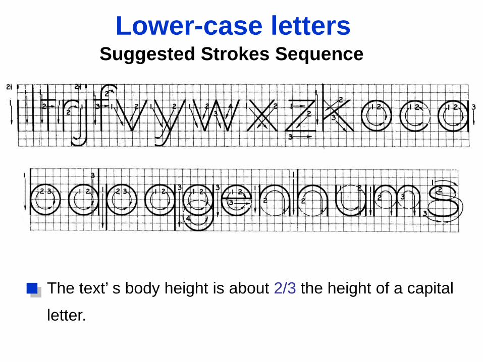
The text’ s body height is about 2/3 the height of a capital
letter.
Lower-case letters Suggested Strokes Sequence
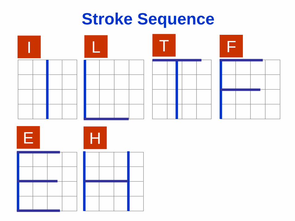
Stroke Sequence
I L T F
E H
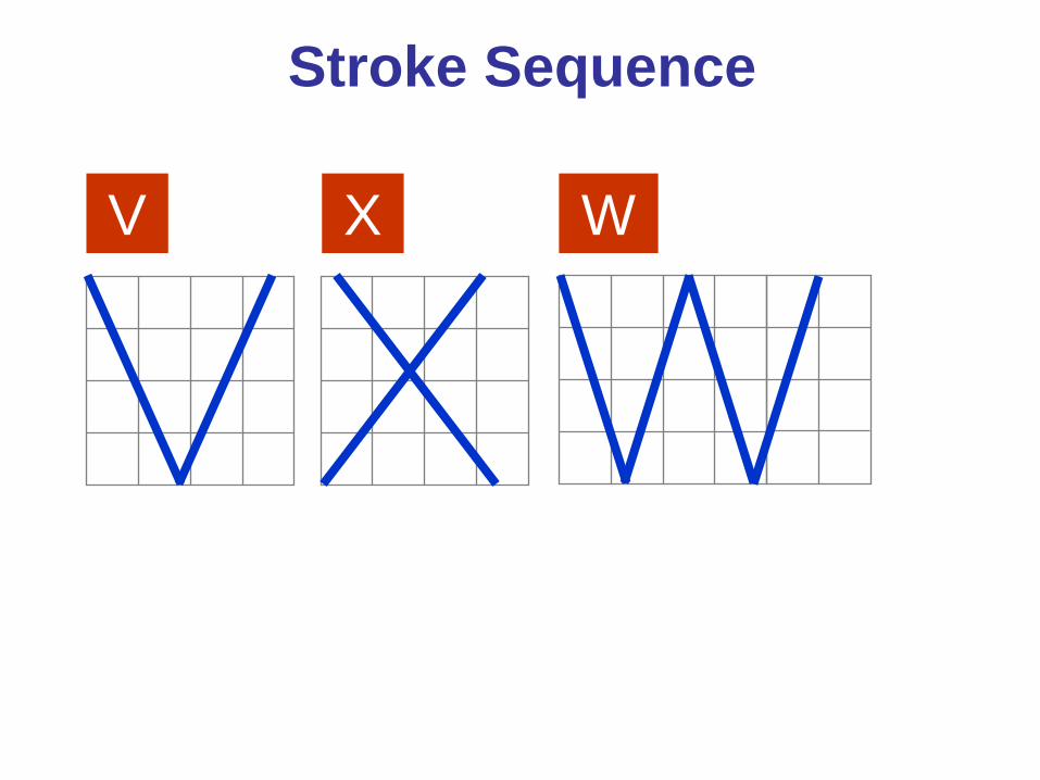
V X W
Stroke Sequence
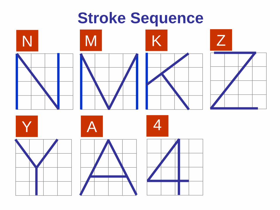
N M K Z
Y A
Stroke Sequence
4
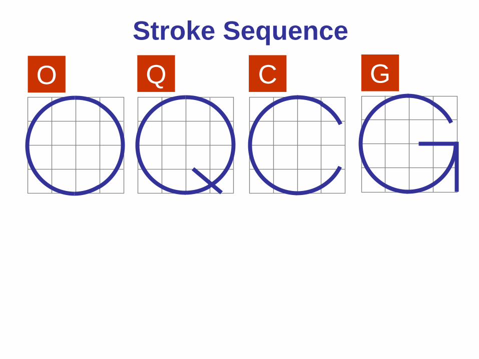
O Q C G Stroke Sequence
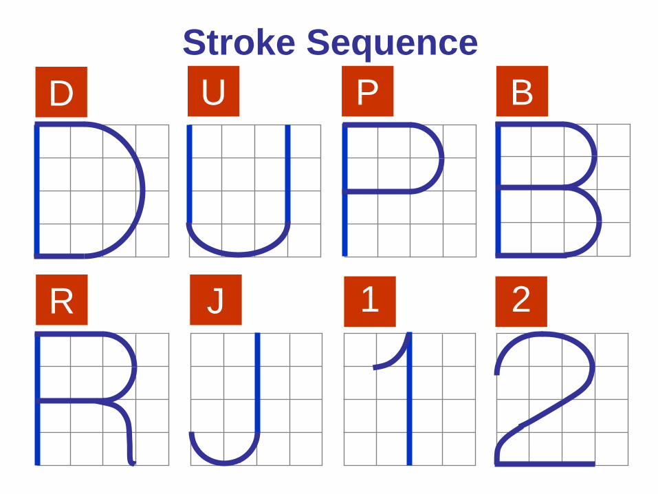
D U P B
R J
Stroke Sequence
1 2
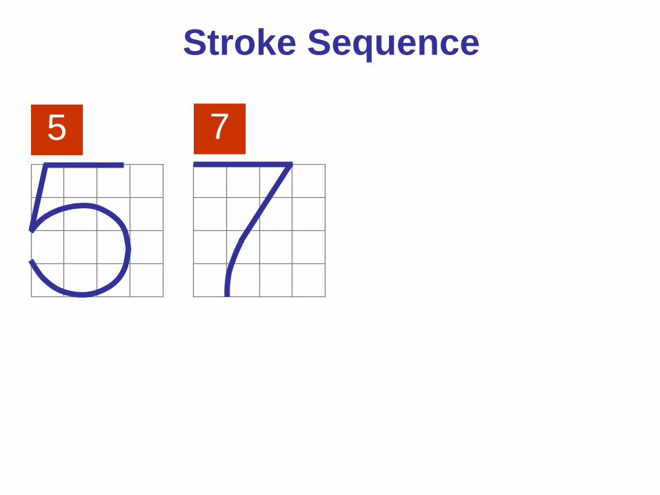
5
Stroke Sequence
7
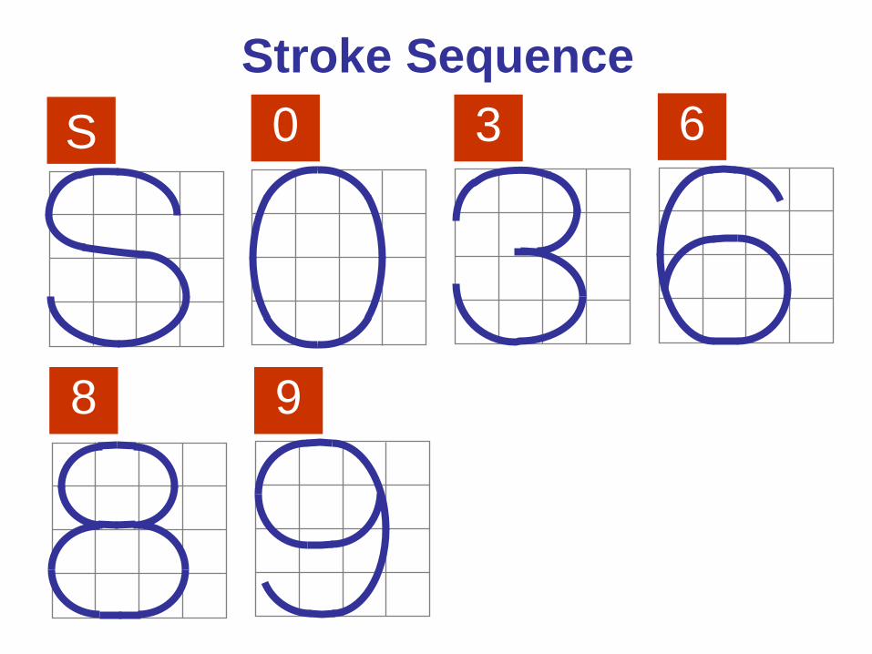
6
8 9
0
Stroke Sequence S 3
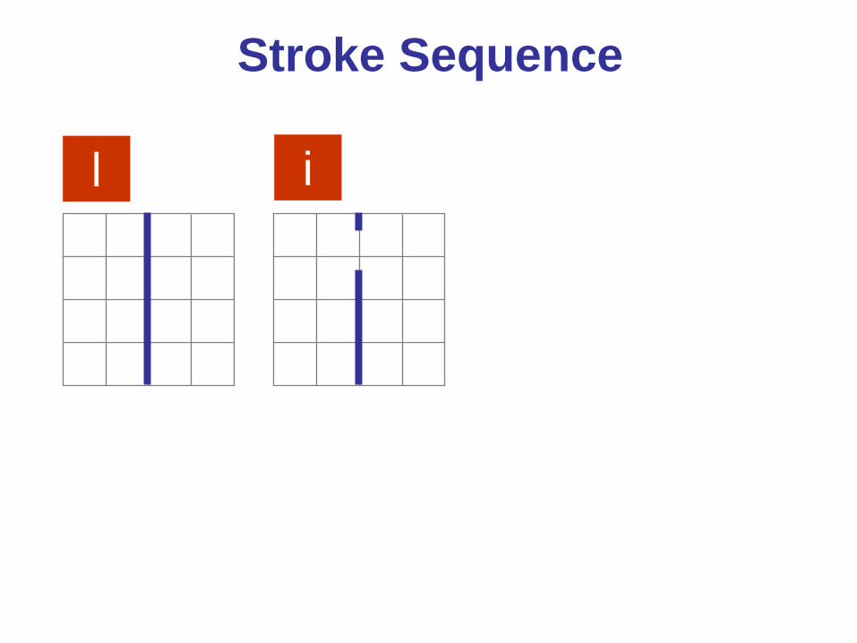
Stroke Sequence
l i
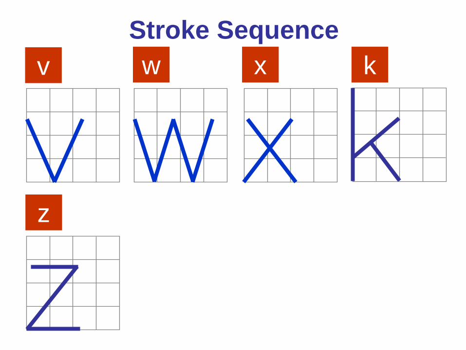
Stroke Sequence v w x k
z
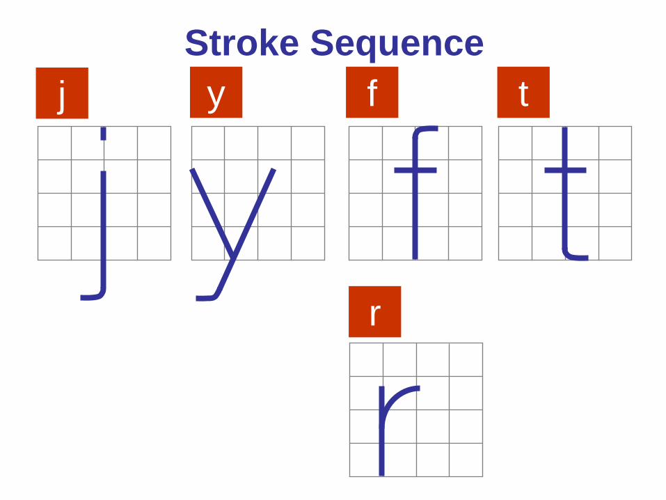
Stroke Sequence j y f
r
t
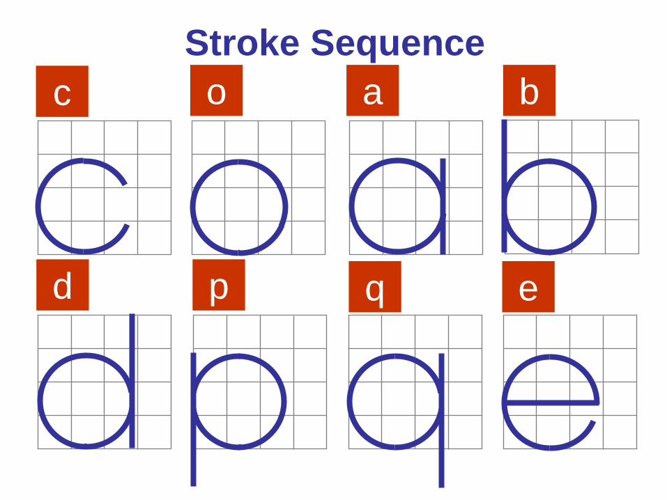
Stroke Sequence c o a b
d p q e
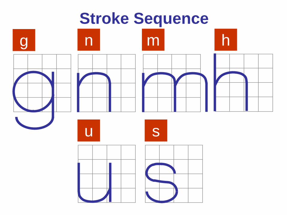
Stroke Sequence g n m h
u s
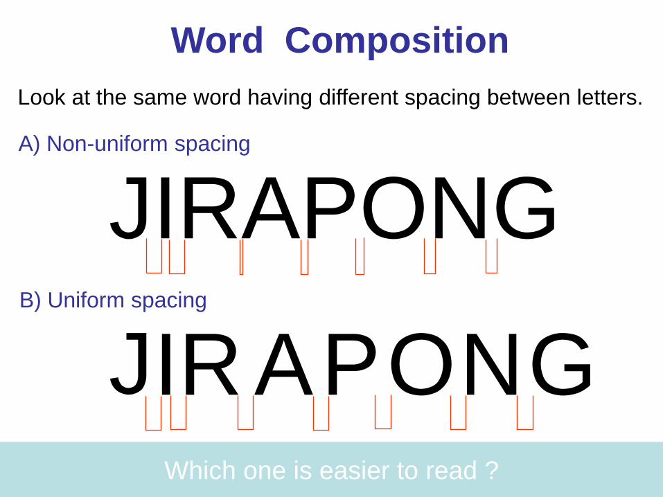
Word Composition Look at the same word having different spacing between letters.
JIRAPONG
J I G O R N P A
Which one is easier to read ?
A) Non-uniform spacing
B) Uniform spacing
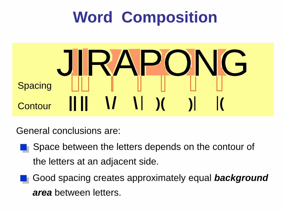
Word Composition
JIRAPONG \ / \ | )( ) | ( |
Space between the letters depends on the contour of the letters at an adjacent side.
Spacing
Contour | | | |
General conclusions are:
Good spacing creates approximately equal background area between letters.
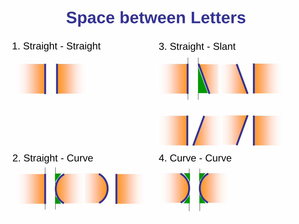
1. Straight - Straight
2. Straight - Curve
3. Straight - Slant
4. Curve - Curve
Space between Letters
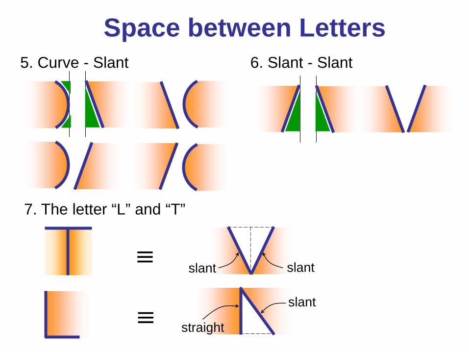
6. Slant - Slant 5. Curve - Slant
7. The letter “L” and “T”
≡ slant slant
≡ slant
straight
Space between Letters
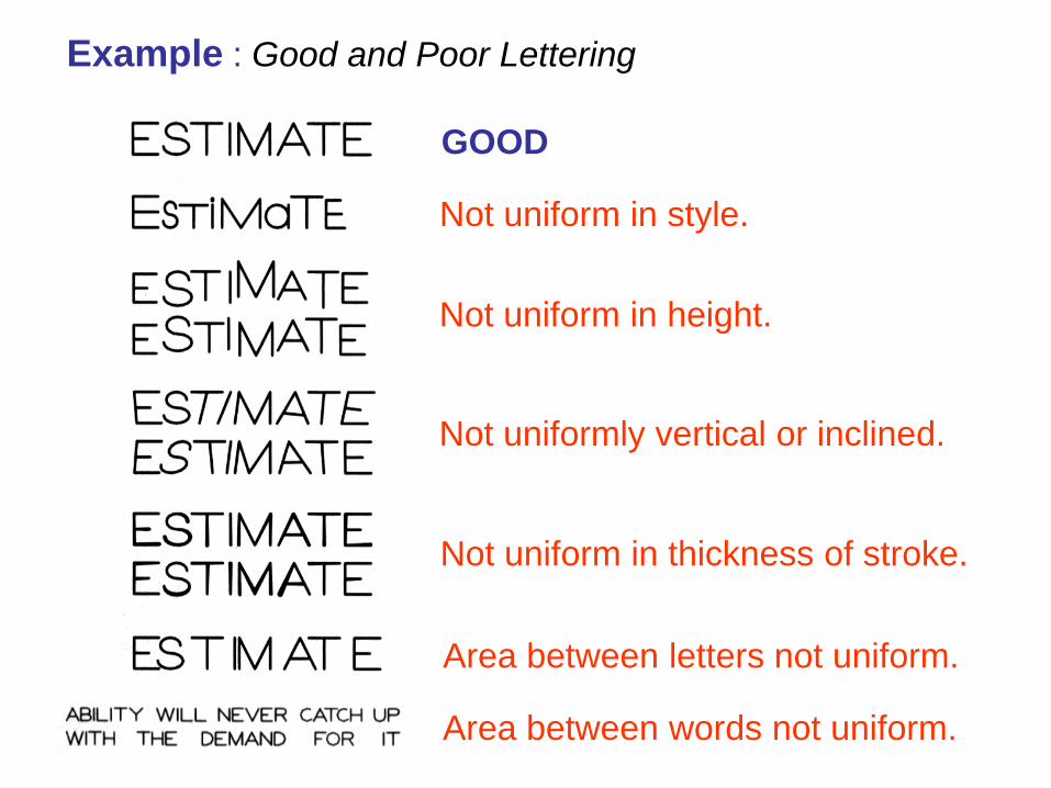
GOOD
Not uniform in style.
Not uniform in height.
Not uniformly vertical or inclined.
Not uniform in thickness of stroke.
Area between letters not uniform.
Area between words not uniform.
Example : Good and Poor Lettering
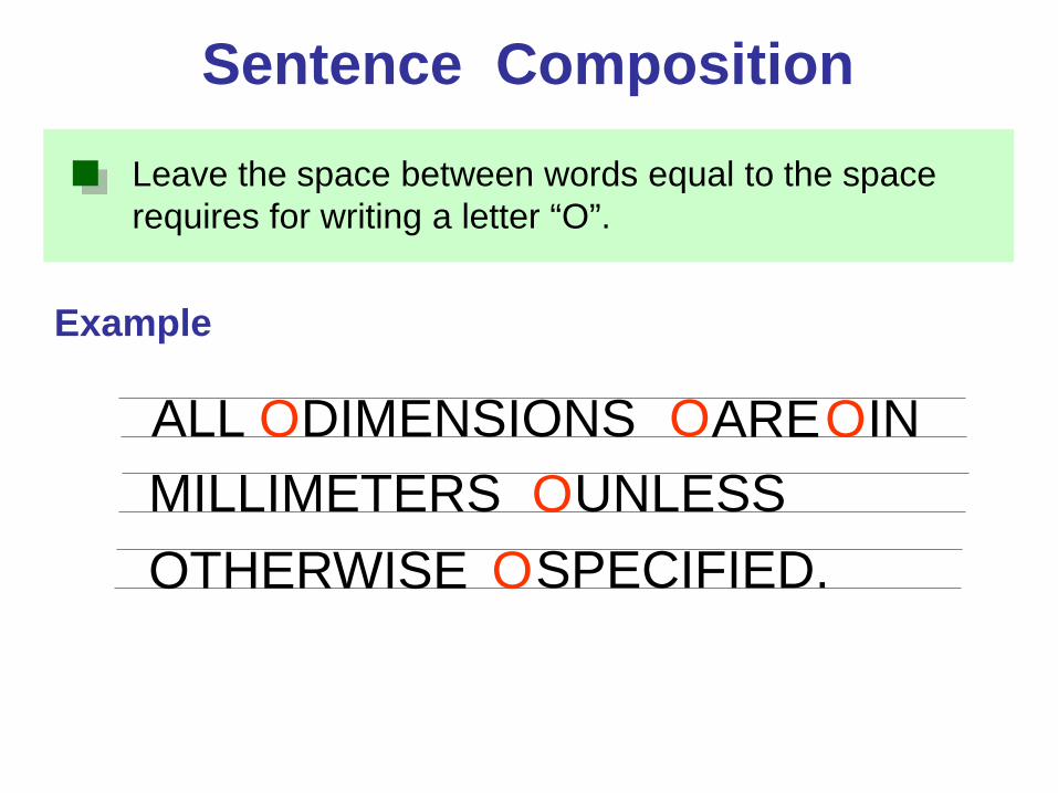
Leave the space between words equal to the space requires for writing a letter “O”.
Example
Sentence Composition
ALL DIMENSIONS ARE IN MILLIMETERS
O O O O UNLESS
OTHERWISE SPECIFIED. O
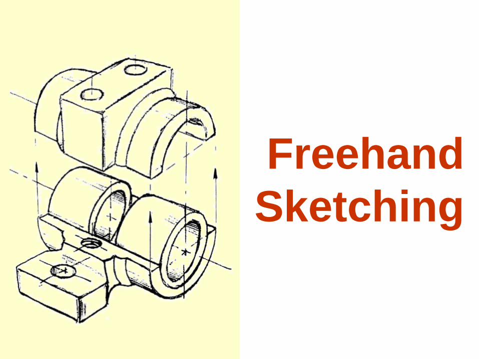
Freehand Sketching
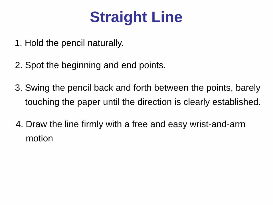
Straight Line 1. Hold the pencil naturally.
2. Spot the beginning and end points.
3. Swing the pencil back and forth between the points, barely touching the paper until the direction is clearly established.
4. Draw the line firmly with a free and easy wrist-and-arm motion
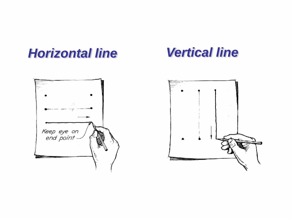
Horizontal line Vertical line
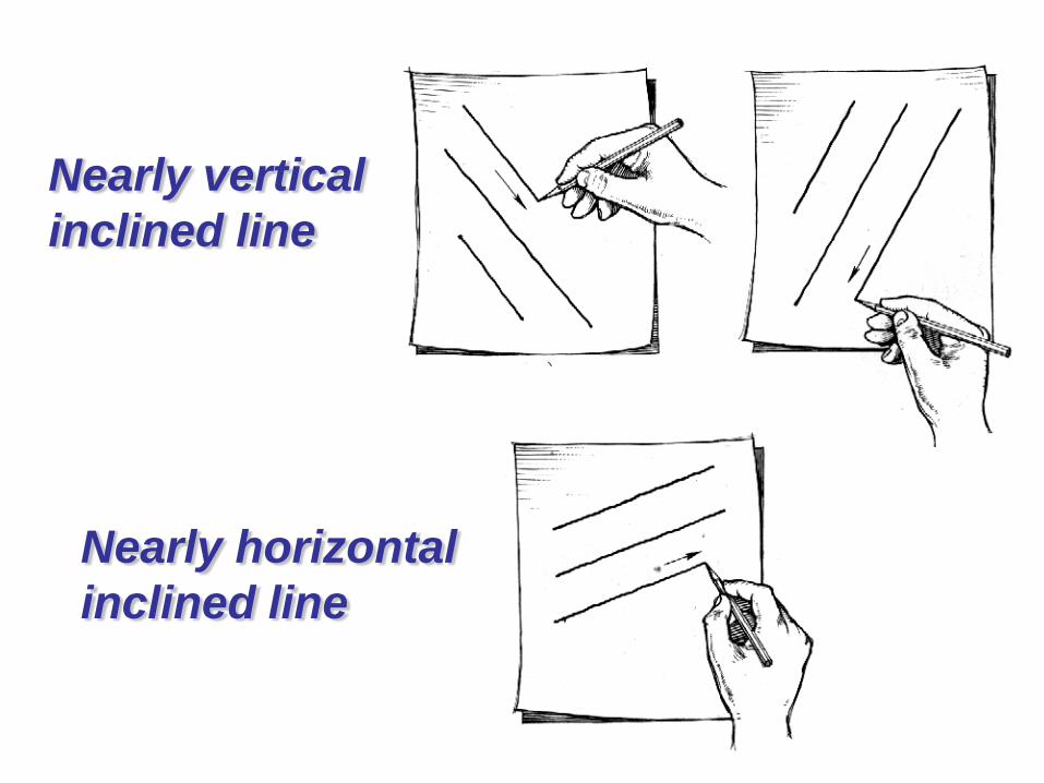
Nearly vertical inclined line
Nearly horizontal inclined line
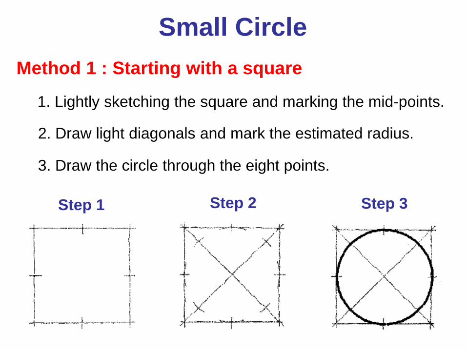
Small Circle Method 1 : Starting with a square
1. Lightly sketching the square and marking the mid-points.
2. Draw light diagonals and mark the estimated radius.
3. Draw the circle through the eight points.
Step 1 Step 2 Step 3
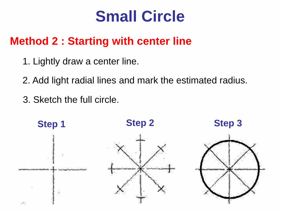
Method 2 : Starting with center line
Step 1 Step 2 Step 3
1. Lightly draw a center line.
2. Add light radial lines and mark the estimated radius.
3. Sketch the full circle.
Small Circle
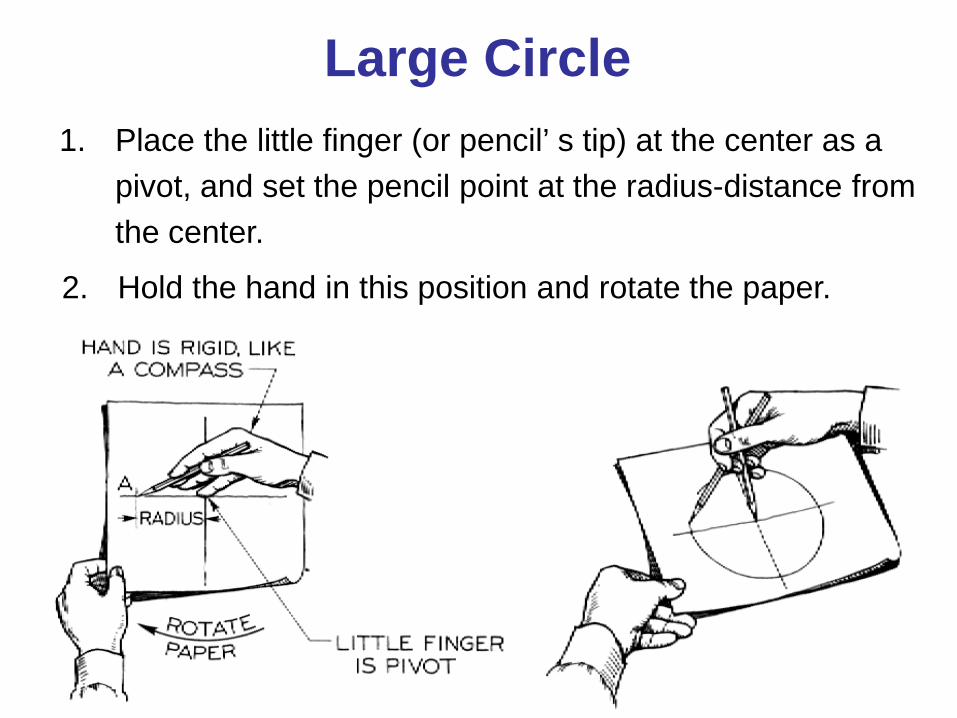
1. Place the little finger (or pencil’ s tip) at the center as a pivot, and set the pencil point at the radius-distance from the center.
2. Hold the hand in this position and rotate the paper.
Large Circle
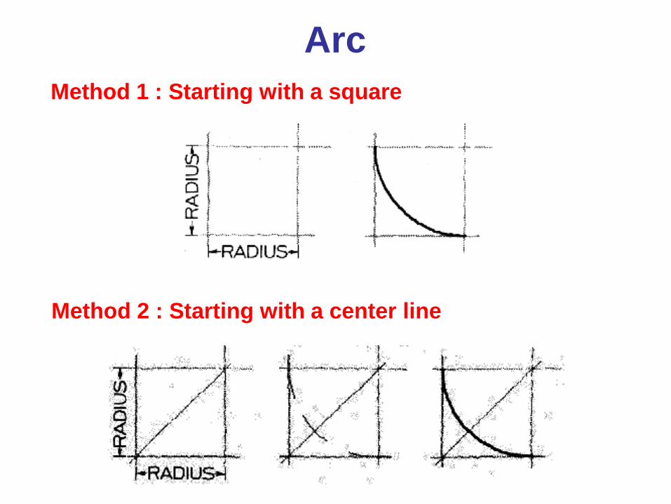
Arc Method 1 : Starting with a square
Method 2 : Starting with a center line
Steps in Sketching
1. Block in main shape.
2. Locate the features.
3. Sketch arcs and circles.
4. Sketch lines.
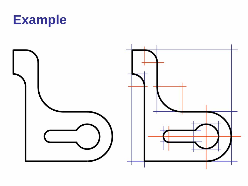
Example