CHAPTER 1 - LTH€¦ · (b) Notice that the references are opposite to the passive sign convention....
21
CHAPTER 1 Exercises E1.1 Charge = Current × Time = (2 A) × (10 s) = 20 C E1.2 A ) 2cos(200 ) 200cos(200 0.01 0t) 0.01sin(20 ( ) ( ) ( t t dt d dt t dq t i = × = = = (b) Notice that the references are opposite to the passive sign convention. Thus we have: E1.3 Because i 2 has a positive value, positive charge moves in the same direction as the reference. Thus positive charge moves downward in element C. Because i 3 has a negative value, positive charge moves in the opposite direction to the reference. Thus positive charge moves upward in element E. E1.4 Energy = Charge × Voltage = (2 C) × (20 V) = 40 J Because v ab is positive, the positive terminal is a and the negative terminal is b. Thus the charge moves from the negative terminal to the positive terminal, and energy is removed from the circuit element. E1.5 i enters terminal a. Furthermore, v is positive at terminal a. Thus the current enters the positive reference, and we have the passive reference configuration. ab ab E1.6 (a) 2 20 ) ( ) ( ) ( t t i t v t p a a a = = J 6667 3 20 3 20 20 ) ( 3 10 0 3 10 0 10 0 2 = = = = = ∫ ∫ t t dt t dt t p w a a 200 20 ) ( ) ( ) ( − = − = t t i t v t p b b b J 1000 200 10 ) 200 20 ( ) ( 10 0 2 10 0 10 0 − = − = − = = ∫ ∫ t t dt t dt t p w b b 1
Transcript of CHAPTER 1 - LTH€¦ · (b) Notice that the references are opposite to the passive sign convention....
CHAPTER 1
Exercises
E1.1 Charge = Current × Time = (2 A) × (10 s) = 20 C
E1.2
A )2cos(200 )200cos(2000.01 0t)0.01sin(20()()( ttdtd
dttdqti =×===
(b) Notice that the references are opposite to the passive sign convention. Thus we have:
E1.3 Because i2 has a positive value, positive charge moves in the same direction as the reference. Thus positive charge moves downward in element C.
Because i3 has a negative value, positive charge moves in the opposite direction to the reference. Thus positive charge moves upward in element E.
E1.4 Energy = Charge × Voltage = (2 C) × (20 V) = 40 J Because vab is positive, the positive terminal is a and the negative
terminal is b. Thus the charge moves from the negative terminal to the positive terminal, and energy is removed from the circuit element.
E1.5 i enters terminal a. Furthermore, v is positive at terminal a. Thus the current enters the positive reference, and we have the passive reference configuration.
ab ab
E1.6 (a)
220)()()( ttitvtp aaa ==
J 66673
203
20 20)(310
0
310
0
10
0
2 ===== ∫ ∫ttdttdttpw aa
20020)()()( −=−= ttitvtp bbb
J 100020010 )20020()(10
02
10
0
10
0
−=−=−== ∫ ∫ ttdttdttpw bb
1
E1.7 (a) Sum of currents leaving = Sum of currents entering ia = 1 + 3 = 4 A
(b) 2 = 1 + 3 + ib ⇒ ib = -2 A (c) 0 = 1 + ic + 4 + 3 ⇒ ic = -8 A
E1.8 Elements A and B are in series. Also, elements E, F, and G are in series.
E1.9 Go clockwise around the loop consisting of elements A, B, and C: -3 - 5 +vc = 0 ⇒ vc = 8 V Then go clockwise around the loop composed of elements C, D and E: - vc - (-10) + v = 0 ⇒ v = -2 V e e
E1.10 Elements E and F are in parallel; elements A and B are in series.
E1.11 The resistance of a wire is given by . Using and
substituting values, we have:
ALR ρ
= 4/2dA π=
⇒ L = 17.2 m
E1.12 ⇒ ⇒ E1.13 ⇒
4/)106.1(1012.16.9 23
6
−
−
×××
=π
L
RVP 2= Ω== 144/2 PVR A 833.0144/120/ === RVI
RVP 2= V 8.15100025.0 =×== PRVmA 8.151000/8.15/ === RVI
E1.14 Using KCL at the top node of the circuit, we have i1 = i2. Then using KVL
going clockwise, we have -v1 - v = 0; but v = 25 V, so we have v = -25 V. Next we have = = v /R = -1 A. Finally, we have
and
2 1 2
i1 i2 2
E1.15 At the top node we have iR = is = 2A. By Ohm’s law we have v = Ri = 80
V. By KVL we have v = v = 80 V. Then p = -v i = -160 W (the minus sign is due to the fact that the references for v and i are opposite to the passive sign configuration). Also we have
W 25)1()25(22 =−×−== ivPR W. 25)1()25(11 −=−×== ivPs
R R
s R s s s
s s
W. 160== RRR ivP
2
Problems
P1.1 Broadly, the two objectives of electrical systems are: 1. To gather, store, process, transport and present information. 2. To distribute, store, and convert energy between various forms.
P1.2 Four reasons that non-electrical engineering majors need to learn the
fundamentals of EE are: 1. To pass the Fundamentals of Engineering Exam. 2. To be able to lead in the design of systems that contain electrical/electronic elements. 3. To be able to operate and maintain systems that contain electrical/electronic functional blocks. 4. To be able to communicate effectively with electrical engineers.
P1.3 Eight subdivisions of EE are: 1. Communication systems. 2. Computer systems. 3. Control systems. 4. Electromagnetics. 5. Electronics. 6. Photonics. 7. Power systems. 8. Signal Processing.
P1.4 Responses to this question are varied.
P1.5 (a) Electrical current is the time rate of flow of net charge through a
conductor or circuit element. Its units are amperes, which are equivalent to coulombs per second. (b) The voltage between two points in a circuit is the amount of energy transferred per unit of charge moving between the points. Voltage has units of volts, which are equivalent to joules per coulomb.
3
(c) The current through an open switch is zero. The voltage across the switch can be any value depending on the circuit. (d) The voltage across a closed switch is zero. The current through the switch can be any value depending of the circuit. (e) Direct current is constant in magnitude and direction with respect to time. (f) Alternating current varies either in magnitude or direction with time.
P1.6 (a) A conductor is anagolous to a frictionless pipe. (b) An open switch is anagolous to a closed valve. (c) A resistance is anagolous to a constriction in a pipe or to a pipe with friction. (d) A battery is analogous to a pump.
P1.7
1819 105.7
ectroncoulomb/el 1060.1coulomb/s 2.1second per Electrons ×=
×=
−
P1.8* The reference direction for points from a to b. Because has a negative value, the current is equivalent to positive charge moving opposite to the reference direction. Finally since electrons have negative charge, they are moving in the reference direction (i.e., from a to b). For a constant (dc) current, charge equals current times the time interval. Thus,
P1.9 The positive reference for v is at the head of the arrow, which is
terminal a. The positive reference for vba is terminal b. Thus, we have
abi abi
C. 15 s) (3A) 5( =×=Q
Also, i is the current entering terminal a, and iba is the current leaving terminal a. Thus, we have Thus, current enters the positive reference and energy is being delivered to the device.
V. 12−=−= vvba
A. 2=−= baii
P1.10 To stop current flow, we break contact between the conducting parts of the switch, and we say that the switch is open. The corresponding fluid
4

analogy is a valve that does not allow fluid to pass through. This corresponds to a closed valve. Thus, a closed valve is analogous to an open switch.
P1.11*
( ) ( ) ( ) A 12122 =+== tdtd
dttdqti
P1.12 (a) The sine function completes one cycle for each 2 radian increase in the angle. Because the angle is 200 one cycle is completed for each time interval of 0.01 s. The sketch is:
π,tπ
C 0318.0
)200cos()200/10( )200sin(10)( (b) 005.0
0
005.0
0
005.0
0
=
=== ∫∫ tdttdttiQ πππ
C 0
)200cos()200/10( )200sin(10)( (c) 01.0
0
01.0
0
01.0
0
=
=== ∫∫ tdttdttiQ πππ
P1.13*
P1.14
coulombs 5.3 |5.37)( 02
0
2
0
=−=== ∞−∞
−∞
∫∫ tt edtedttiQ
( ) A 823)()( 44 tt eedtd
dttdqti −− =−==
P1.15 The number of electrons passing through a cross section of the wire per second is
secondelectrons/ 105.12106.1
20 1919 ×=
×=
−N
5
The volume of copper containing this number of electrons is
31029
19
m 105.1210
105.12volume −×=×
=
The cross sectional area of the wire is
262
m 10297.24
−×==dA π
Finally, the average velocity of the electrons is
P1.16* The charge flowing through the battery is
mm/s 5443.0volume==
Au
coulombs 10432)seconds 360024()amperes 5( 3×=××=Qand the stored energy is
(a) Equating gravitational potential energy, which is mass times height times the acceleration due to gravity, to the energy stored in the battery and solving for the height, we have
joules10184.5)12()10432(Energy 63 ×=××==QV
km 6.178.93010184.5Energy 6
=××
==mg
h
(b) Equating kinetic energy to stored energy and solving for velocity, we have
(c) The energy density of the battery is
m/s 9.587Energy2=
×=
mv
which is about 0.384% of the energy density of gasoline.
J/kg 108.17230
10184.5 36
×=×
P1.17
Because iba is positive, if the current were carried by positive charge it would be entering terminal b. Electrons enter terminal a. The energy is taken from the element.
coulombs 40)seconds 20()amperes 2(time current =×=×=Q joules200)10(20)(Energy =×==QV
6
P1.18
joules 104.149106.1 gains electron The 1919 −− ×=××
P1.19*
coulombs 1044.1)seconds 000,36()amperes 4(time current 5×=×=×=Q
joules 10016.2)14()101.44(Energy 65 ×=××==QV
P1.20 If the current is referenced to flow into the positive reference for the voltage, we say that we have the passive reference configuration. Using double subscript notation, if the order of the subscripts are the same for the current and voltage, we have a passive reference configuration.
P1.21* (a) P -vaia = 30 W Energy is being absorbed by the element.
(b) P vbib = 30 W Energy is being absorbed by the element.
=
= (c) P -vDEi = -60 W Energy is being supplied by the element. = ED
P1.22 The amount of energy is Because the
reference polarity is positive at terminal a and the voltage value is negative, terminal b is actually the positive terminal. Because the charge moves from the negative terminal to the positive terminal, energy is removed from the device.
J. 30 V) (10C) (3 =×==QVW
P1.23* .
To increase the chemical energy stored in the battery, positive charge should move from the positive terminal to the negative terminal, in other words from a to b. Electrons move from b to a.
C 50 V) (12J) (600 === VwQ
P1.24
Energy
( ) ( ) ( ) W 20 tetitvtp −==
∫∞
∞− =−==0
0 joules 20 |20)( tedttp
The element absorbs the energy.
7

P1.25
W )200sin(50)( a)( tivtp abab π==
J 1592.0
)200cos()200/50( )200sin(50)( (b) 005.0
0
005.0
0
005.0
0
=
=== ∫∫ tdttdttpw πππ
P1.26*
J 0
)200cos()200/50( )200sin(50)( (c) 01.0
0
01.0
0
01.0
0
=
=== ∫∫ tdttdttpw πππ
kWh 1.457$/kWh 0.14
$64RateCost Energy ===
W 634.9 h 2430
kWh 457.1Time
Energy=
×==P A 162.5
1239.634===
VPI
%24.10%1009.634
65Reduction =×=
P1.27 (a) P 60 W delivered to element A. (b) (c) P 60 W delivered to element A.
P1.28* (a) (b)
=A. element from taken W 60=P
=
. element from taken W 60 AP =. element to delivered W 60 AP =
(c)
P1.29 The power that can be delivered by the cell is In 71 hours, the energy is Thus, the unit cost of the energy is
. element from taken W 60 AP =
W. 84.0==vipkWhr. 0.05964 Whr 64.59 === pTW$/kWhr. 05.9=)05964.0/()54.0(=Cost
8
P1.30 The current supplied to the electronics is The ampere-hour rating of the battery is the operating time to discharge the battery multiplied by the current. Thus, the operating time is
The energy delivered by the battery is Neglecting the cost of
recharging, the cost of energy for 300 discharge cycles is
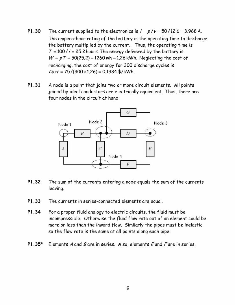
P1.31 A node is a point that joins two or more circuit elements. All points
joined by ideal conductors are electrically equivalent. Thus, there are four nodes in the circuit at hand:
A. 968.36.12/50/ === vpi
hours. 2.25/100 == iTkWh. 1.26wh 1260)2.25(50 ==== pTW
$/kWh. 1984.0)26.1300/(75 =×=Cost
P1.32 The sum of the currents entering a node equals the sum of the currents
leaving. P1.33 The currents in series-connected elements are equal.
P1.34 For a proper fluid analogy to electric circuits, the fluid must be
incompressible. Otherwise the fluid flow rate out of an element could be more or less than the inward flow. Similarly the pipes must be inelastic so the flow rate is the same at all points along each pipe.
P1.35* Elements A and B are in series. Also, elements E and F are in series.
9
P1.36 (a) Elements C and D are in series. (b) Because elements C and D are in series, the currents are equal in magnitude. However, because the reference directions are opposite, the algebraic signs of the current values are opposite. Thus, we have . (c) At the node joining elements A, B, and C, we can write the KCL equation . Also we found earlier that
dc ii −=
A 4 1 3 =+=+= cab iiiA. 1− =−= cd ii
P1.37* At the node joining elements A and B, we have Thus,
For the node at the top end of element C, we have . Thus, . Finally, at the top right-hand corner node, we have
Thus, . Elements A and B are in series.
P1.38* We
.0=+ ba ii A. 2 −=ai3=+ cb ii
A 1=ci .d3 e ii =+ A 4 =di
find we KCL, Applying A. 3 and A, 5 A, 4 A, 2 given are =−=== hdba iiii
P1.39 Applying KCL, we find
A 2=−= abc iii 5=+= hce iii AA 3−=+= daf iii A 6−=−= hfg iii
A. 1 and A, 5 A, 3 A, 1 given are We ===−= hgca iiii
P1.40 If one travels around a closed path adding the voltages for which one enters the positive reference and subtracting the voltages for which one enters the negative reference, the total is zero.
A 2=+= acb iii 4=+= hce iii AA 7=−= afd iii A 6=+= hgf iii
P1.41 (a) Elements A and B are in parallel.
(b) Because elements A and B are in parallel, the voltages are equal in magnitude. However because the reference polarities are opposite, the algebraic signs of the voltage values are opposite. Thus, we have
(c) Writing a KVL equation while going clockwise around the loop composed of elements A, C and D, we obtain Solving for
and substituting values, we find Also we have
.ba vv −=
.0=−− cda vvvcv V. 8=cv
V. 3−=−= ab vv
10
P1.42* Summing voltages for the lower left-hand loop, we have − which yields Then for the top-most loop, we have
which yields Finally, writing KCL around the outside loop, we have which yields
,0111 =++ avV. 10−=av
,015 =−− ac vv V. 5=cv,01 =++− bc vv V. 4−=bv
P1.43 We are given Applying KVL, we find
V. 6 and V, 10 V, 7 V, 5 =−=== hfba vvvv
V 12=+= bad vvv V 1−=−−−= hfac vvvvV 8=+−−= dcae vvvv V 2=−= heg vvv
V 7=+= ecb vvv P1.44* Applying KCL and KVL, we have
A 1=−= dac iii 2−=−= ab ii A The power for each element is
V 6−=−= adb vvv V 4== dc vv
W 20−=−= aaA ivP W 12== bbB ivPW 4== ccC ivP 4== ddD ivP W
0 Thus, =+++ DCBA PPPP
P1.45 (a) In Figure P1.28, elements C, D, and E are in parallel. (b) In Figure P1.33, no element is in parallel with another element. (c) In Figure P1.34, elements C and D are in parallel.
P1.46 Applying KVL to the loop abca, substituting values and solving, we obtain: Similarly, applying KVL to the loop abcda, substituting values and solving, we obtain:
0=−− accbab vvv0124 =−− acv 8−=acv V
0=++− dacdcbab vvvv
P1.47 (a) The voltage between any two points of an ideal conductor is zero
regardless of the current flowing.
15124 =−+− cdv 0V 23=cdv
11
(b) An ideal voltage source maintains a specified voltage across its terminals. (c) An ideal current source maintains a specified current through itself.
P1.48 Four types of controlled sources and the units for their gain constants
are: 1. Voltage-controlled voltage sources. V/V or unitless. 2. Voltage-controlled current sources. A/V or siemens. 3. Current-controlled voltage sources. V/A or ohms. 4. Current-controlled current sources. A/A or unitless.
P1.49 Provided that the current reference points into the positive voltage
reference, the voltage across a resistance equals the current through the resistance times the resistance. On the other hand, if the current reference points into the negative voltage reference, the voltage equals the negative of the product of the current and the resistance.
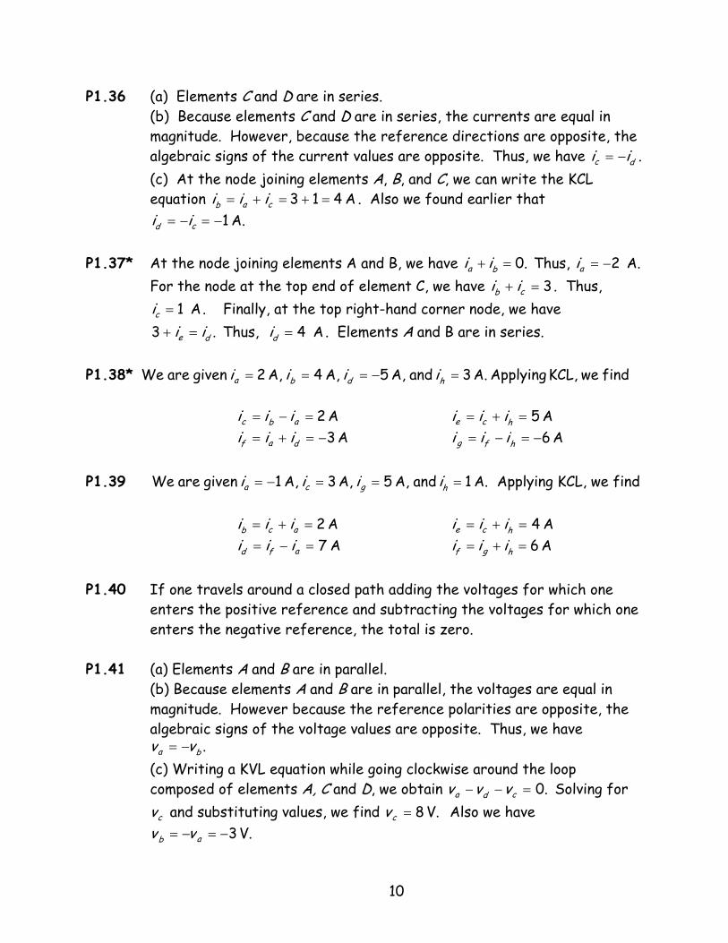
P1.50*
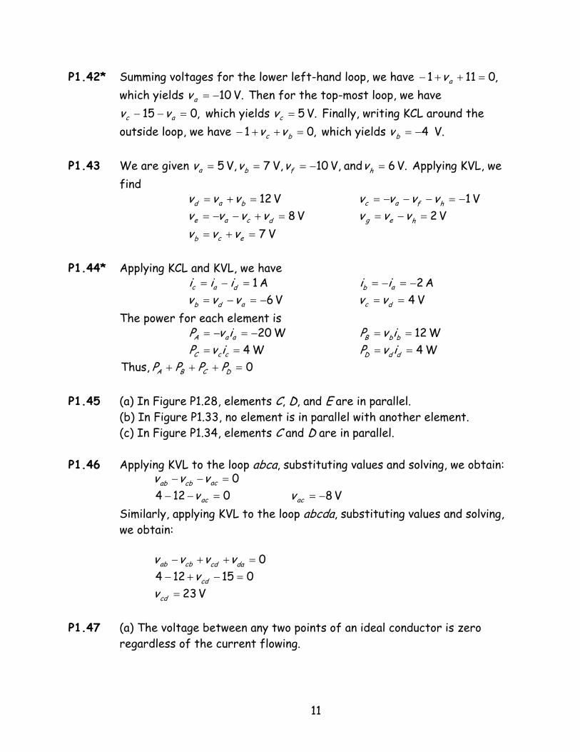
P1.51
12
P1.52 The resistance of the copper wire is given by , and the resistance of the nichrome wire is . Taking the ratios of the respective sides of these equations yields . Solving for and substituting values, we have
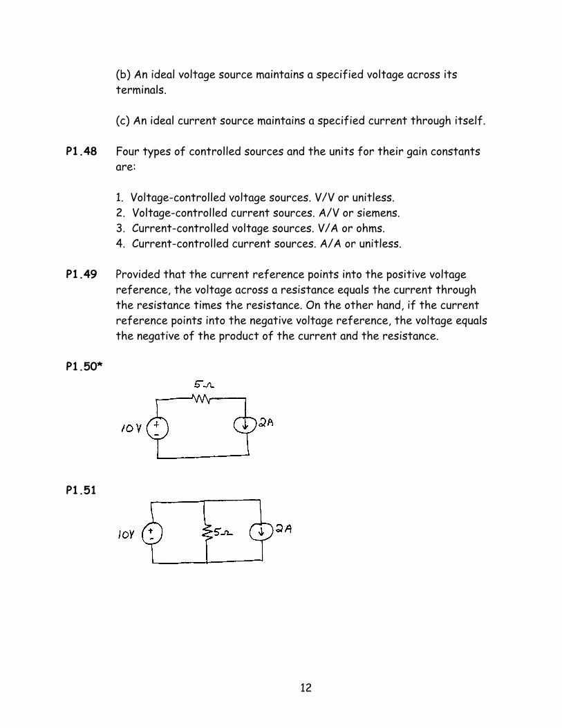
P1.53
ALR CuCu ρ=
ALR WW ρ=
CuWCuW RR ρρ=
WR
Ω=
×××=
=−
22.8 )1072.1()10 (1.12 (0.35) 86-
CuWCuW RR ρρ
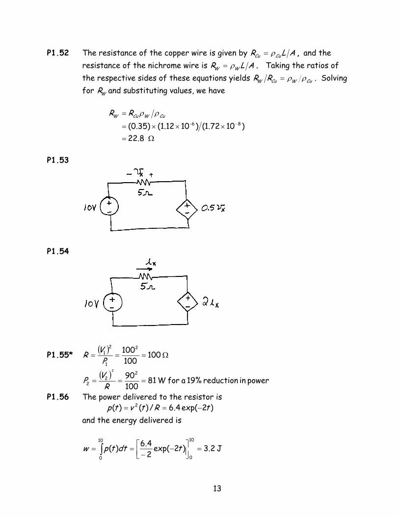
P1.54
P1.55*
( )Ω=== 100
1001002
1
21
PVR
( ) power in reduction 19% a for W 81100902
22
2
===R
VP
P1.56 The power delivered to the resistor is and the energy delivered is
)2exp(4.6/)()( 2 tRtvtp −==
J 2.3)2exp(24.6)(
10
0
10
0
=
−−
== ∫ tdttpw
13
P1.57 The power delivered to the resistor is
)4cos(2162.02162.0)2(sin4324.0/)()( 22 ttRtvtp ππ −===
and the energy delivered is
J 108.4)(19
0
== ∫ dttpw
P1.58 Equation 1.10 gives the resistance as
(a) Thus, if the length of the wire is doubled, the resistance doubles to 1 (b) If the diameter of the wire is doubled, the cross sectional area A is
ALR ρ
=
. Ω
increased by a factor of four. Thus, the resistance is decreased by a factor of four to 0.125 Ω
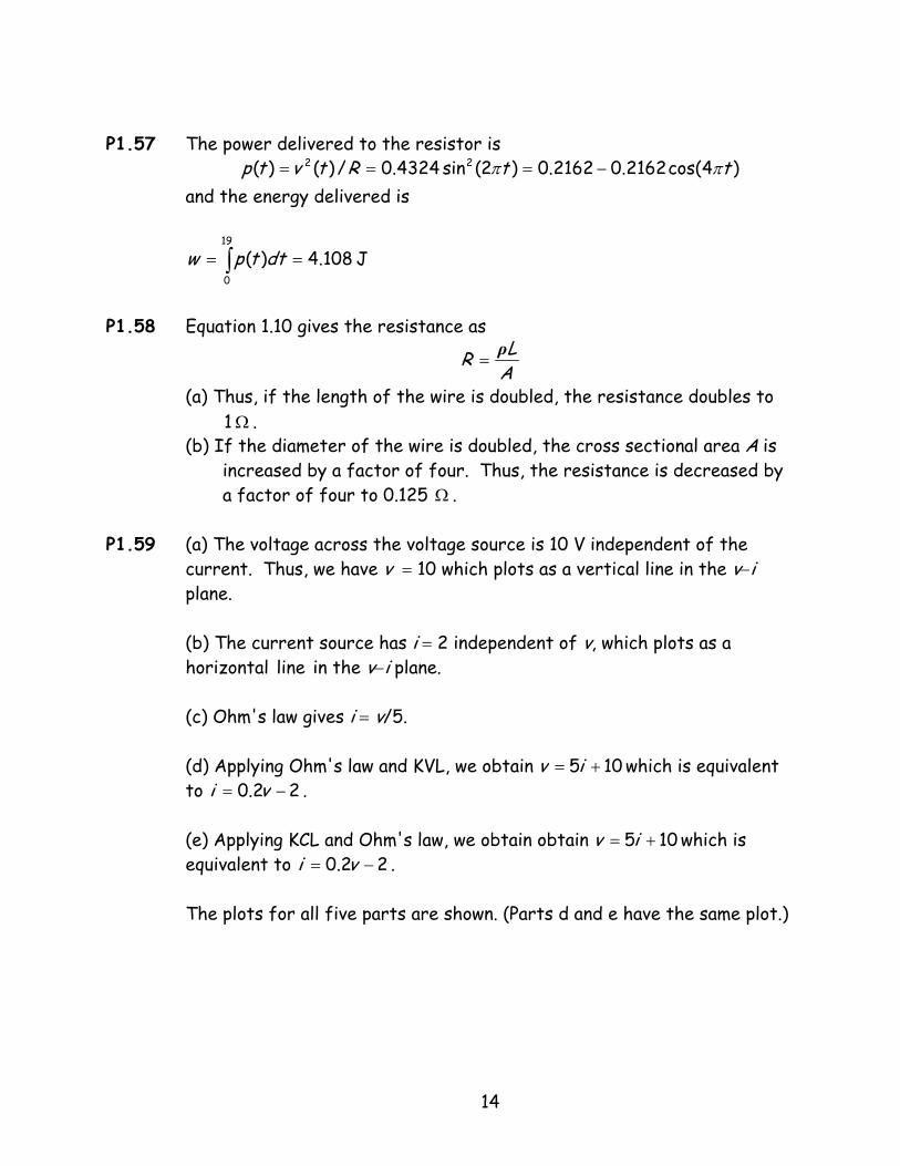
P1.59 (a) The voltage across the voltage source is 10 V independent of the
current. Thus, we have v = 10 which plots as a vertical line in the v−i plane.
.
(b) The current source has i = 2 independent of v, which plots as a horizontal line in the v−i plane. (c) Ohm's law gives i = v/5. (d) Applying Ohm's law and KVL, we obtain which is equivalent to .
105 += iv22.0 −= vi
(e) Applying KCL and Ohm's law, we obtain obtain which is equivalent to . The plots for all five parts are shown. (Parts d and e have the same plot.)
105 += iv22.0 −= vi
14
P1.60* (a) Not contradictory. (b) A 2-A current source in series with a 3-A current source is contradictory because the currents in series elements must be equal. (c) Not contradictory. (d) A 2-A current source in series with an open circuit is contradictory because the current through a short circuit is zero by definition and currents in series elements must be equal. (e) A 5-V voltage source in parallel with a short circuit is contradictory because the voltages across parallel elements must be equal and the voltage across a short circuit is zero by definiton.
P1.61 The power for each element is 20 W. The current source delivers power and the voltage source absorbs it.
15

P1.62*
As shown above, the 2 A current circulates clockwise through all three elements in the circuit. Applying KVL, we have
V 2010510 =+=+= RRc ivv
Thus, the current source delivers power.
The resistor absorbs power.
The voltage source absorbs power.
W. 40−=−=− Rcsourcecurrent ivP
W. 2052)( 22 =×== RiP RR
W. 2010 =×=− Rsourcevoltage iP
P1.63 This is a parallel circuit and the voltage across each element is 10 V positive at the top end. Thus, the current through the resistor is
Applying KCL, we find that the current through the voltage source is zero. Computing power for each element, we find
A 2 5V 10=
Ω=Ri
W 20−=−sourcecurrentP
Thus, the current source delivers power.
W 20)( 2 == RiP RR
0=−sourcevoltageP
16
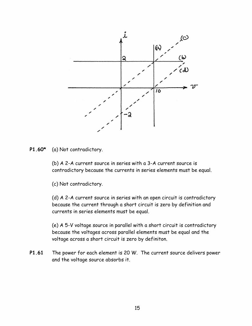
P1.64*
Applying Ohm's law, we have . However,
, and . Applying KCL, we have
. By Ohm's law: . Finally using KVL, we have .
( ) ( ) V 28A 7 42 =×Ω=v 2vThus, parallel.three all across voltage the is in are that resistors
A 6.552
3 ==vi A 75.1
162
2 ==vi
A 35.147321 =++= iii V 75.715 11 == ivV 75.9921 =+= vvvx
P1.65
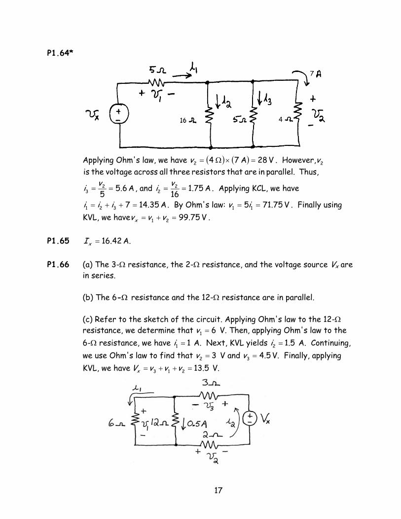
P1.66 (a) The 3-Ω resistance, the 2-Ω resistance, and the voltage source Vx are in series. (b) The 6-Ω resistance and the 12-Ω resistance are in parallel.
A. 42.16=xI
(c) Refer to the sketch of the circuit. Applying Ohm's law to the 12-Ω resistance, we determine that V. Then, applying Ohm's law to the 6-Ω resistance, we have A. Next, KVL yields A. Continuing, we use Ohm's law to find that V and V. Finally, applying KVL, we have V.
61 =v11 =i 5.12 =i
32 =v 5.43 =v5.13213 =++= vvvVx
17
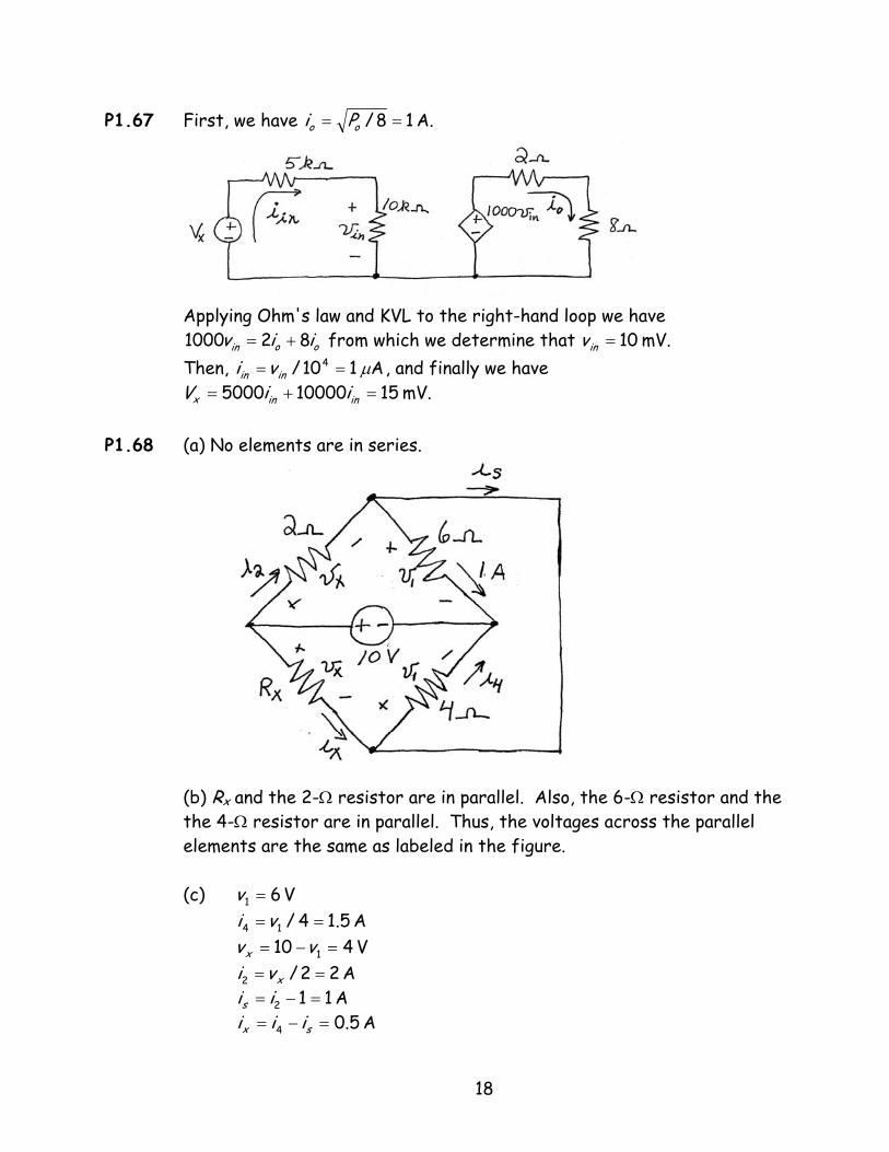
P1.67 First, we have A. 18/ == oo Pi
Applying Ohm's law and KVL to the right-hand loop we have
from which we determine that Then, , and finally we have
P1.68 (a) No elements are in series.
(b) R and the 2-Ω resistor are in parallel. Also, the 6-Ω resistor and the the 4-Ω resistor are in parallel. Thus, the voltages across the parallel elements are the same as labeled in the figure.
ooin iiv 821000 += mV. 10=invA 110/ 4 µ== inin vi
mV. 15100005000 =+ inin=x iiV
x
(c) V 61 =v
A 5.14/14 ==vi
V 410 1 =−= vvx
A 22/2 == xvi
A 112 =−= iis
A 5.04 =−= sx iii
18
Ω== 8/ xxx ivR
P1.69 V A A
P1.70* (a) Applying KVL, we have 10 , which yields
(b)
12/12 vi = 6/6 vi = 36/12/612 =+=+ vvii12=v 112 =i 26 =i
xx vv 5+= V 667.16/10 ==xv
A 5556.03/ == xx vi (c) (This represents power delivered by
the voltage source.)
W. 556.510 −=−=− xsourcevoltage iP
(absorbed) W 926.0)(3 2 == xR iP
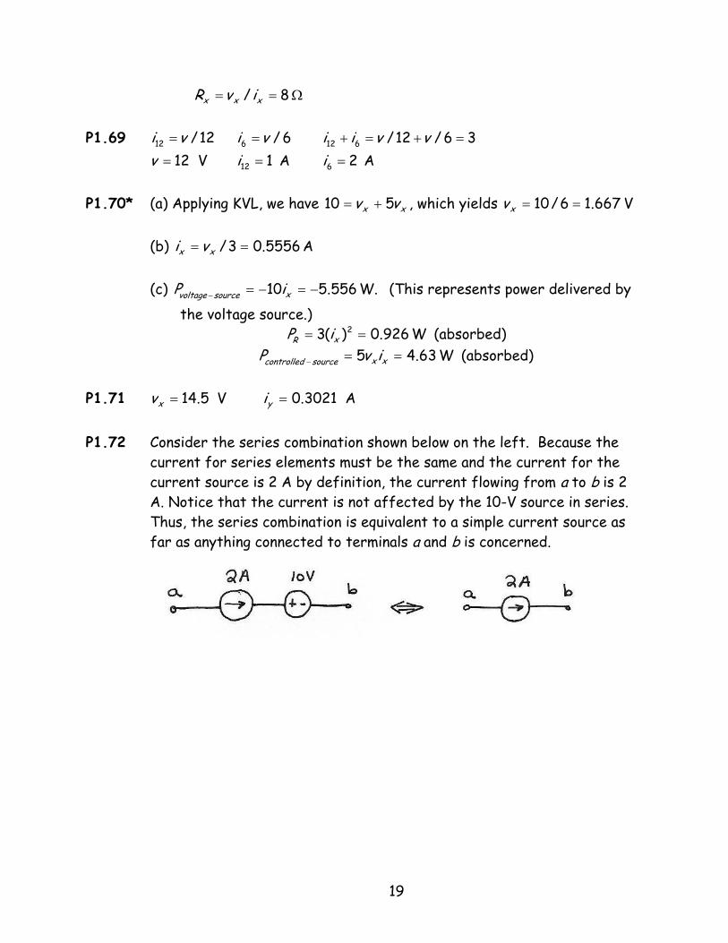
P1.71 V A P1.72 Consider the series combination shown below on the left. Because the
current for series elements must be the same and the current for the current source is 2 A by definition, the current flowing from a to b is 2 A. Notice that the current is not affected by the 10-V source in series. Thus, the series combination is equivalent to a simple current source as far as anything connected to terminals a and b is concerned.
(absorbed) W 63.45 ==− xxsourcecontrolled ivP
5.14=xv 3021.0=yi
19
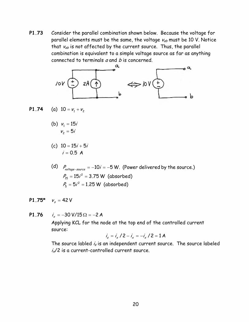
P1.73 Consider the parallel combination shown below. Because the voltage for parallel elements must be the same, the voltage vab must be 10 V. Notice that v is not affected by the current source. Thus, the parallel combination is equivalent to a simple voltage source as far as anything connected to terminals a and b is concerned.
ab
P1.74 (a) 10
21 vv +=
(b)
iv 151 =iv 52 =
(c) 10
ii 515 +=A 5.0=i
(d)
V
(absorbed) W 25.15(absorbed) W 75.315
source.) the by delivered (Power W. 510
25
215
==
==
−=−=−
iPiP
iP sourcevoltage
P1.75*
42=sv
P1.76 Applying KCL for the node at the top end of the controlled current source:
The source labled is is an independent current source. The source labeled
ix/2 is a current-controlled current source.
A 2 V/15 30 −=Ω−=xi
A 12/2/ =−=−= xxxs iiii
20
P1.77 Applying Ohm's law and KVL, we have 20 Solving, we obtain
The source labeled 20 V is an independent voltage source. The source labeled 5ix is a current-controlled voltage source.
.510 xx ii =+A. 4−=xi
21