Chapter 1 INTRODUCTION TO NORMAL BINOCULAR VISION
14
Chapter 1 INTRODUCTION TO NORMAL BINOCULAR VISION 1.1 The end product of binocular vision Normal binocular vision is defined as the integration of monocular sensory and motor visual information into a combined percept of the surrounding physical space. This visual percept is heavily edited by the brain. It is affected by visual memory, and we sometimes react to visual stimuli before they pass into consciousness. This book sets out the processes and equipment involved in that editing. Human binocular vision has several advantages over monocular vision. The obvious advantage is single vision rather than double vision, or vision alternating between each eye. Next, the subtle difference between the right and left viewpoints allows the most accurate form of depth perception, stereopsis. It is possible to see the effect of the different viewpoints in bin- ocular vision by holding a hand edge in front of the eyes, and then closing each eye in turn. Stereopsis assists primates in hand–eye coordination and in precise interception of mobile food sources. Stereopsis helps to identify threats – adversaries may be spotted moving across the visual field with monocular vision, but when stationary, three-dimensional vision helps to identify a specific threat from background visual information. This is known as figure–ground separation, or breaking camouflage. With binocular vision, the amount of binocular convergence used to fixate a target with each eye allows an approximate assessment of the target distance by triangulation. Binocular vision also helps with spatial localisation: visual attention can be concentrated on objects situated in the plane of the binocular fixation point, allowing distracting stimuli nearer or farther away to be ignored. Binocular perception has advantages over monocular vision in assessing surface cur- vature. It also allows enhanced surface material perception using lustre perception. At a higher level of visual performance, fine stereopsis allows very precise detailed tasks, e.g. using binocular operating microscopes, or mapping the apparent height of terrain using stereoscopic photographs. The brain also averages the visual input when combining right and left eye images, so that an individual with early cataract, who sees a letter ‘O’ as a ‘Q’ with one eye and as an inverted ‘Q’ with the other eye, correctly perceives ‘O’ in binocular vision. This process, binocular visual summation, improves bin- ocular performance over monocular for: Normal Binocular Vision: theory, investigation and practical aspects. By David Stidwill and Robert Fletcher. © 2011 Blackwell Publishing Ltd 1 COPYRIGHTED MATERIAL
Transcript of Chapter 1 INTRODUCTION TO NORMAL BINOCULAR VISION
Chapter 1
INTRODUCTION TO NORMAL BINOCULAR VISION
1.1 The e nd p roduct of b inocular v ision
Normal binocular vision is defi ned as the integration of monocular sensory and motor visual information into a combined percept of the surrounding physical space. This visual percept is heavily edited by the brain. It is affected by visual memory, and we sometimes react to visual stimuli before they pass into consciousness. This book sets out the processes and equipment involved in that editing.
Human binocular vision has several advantages over monocular vision. The obvious advantage is single vision rather than double vision, or vision alternating between each eye. Next, the subtle difference between the right and left viewpoints allows the most accurate form of depth perception, stereopsis . It is possible to see the effect of the different viewpoints in bin-ocular vision by holding a hand edge in front of the eyes, and then closing each eye in turn. Stereopsis assists primates in hand – eye coordination and in precise interception of mobile food sources. Stereopsis helps to identify threats – adversaries may be spotted moving across the visual fi eld with monocular vision, but when stationary, three - dimensional vision helps to identify a specifi c threat from background visual information. This is known as fi gure – ground separation , or breaking camoufl age. With binocular vision, the amount of binocular convergence used to fi xate a target with each eye allows an approximate assessment of the target distance by triangulation. Binocular vision also helps with spatial localisation : visual attention can be concentrated on objects situated in the plane of the binocular fi xation point, allowing distracting stimuli nearer or farther away to be ignored. Binocular perception has advantages over monocular vision in assessing surface cur-vature . It also allows enhanced surface material perception using lustre perception.
At a higher level of visual performance, fi ne stereopsis allows very precise detailed tasks, e.g. using binocular operating microscopes, or mapping the apparent height of terrain using stereoscopic photographs. The brain also averages the visual input when combining right and left eye images, so that an individual with early cataract, who sees a letter ‘ O ’ as a ‘ Q ’ with one eye and as an inverted ‘ Q ’ with the other eye, correctly perceives ‘ O ’ in binocular vision. This process, binocular visual summation , improves bin-ocular performance over monocular for:
Normal Binocular Vision: theory, investigation and practical aspects. By David Stidwill and Robert Fletcher. © 2011 Blackwell Publishing Ltd
1
COPYRIG
HTED M
ATERIAL

2 ■ Normal Binocular Vision
• high - contrast visual acuity, and the upper spatial frequencies of contrast sensitivity;
• absolute light detection at threshold of perception; • threshold contrast sensitivity function; • reaction time to fl ashing visual stimuli, e.g. sine - wave bar gratings.
This can be important in several occupational situations.
Two eyes and binocular vision supply a paired and therefore spare organ , true for many of the body ’ s functions as insurance against injury and disease. Two eyes also give a wider fi eld of vision . In animals that are subject to predators, the horizontal visual fi eld may extend to 360 degrees, i.e. panoramic vision . In humans, the horizontal binocular visual fi eld is 120 degrees, with a further monocular fi eld of about 45 degrees (the temporal crescents) on each side of the binocular fi eld, on the horizontal (medial - lateral) axis passing through the eyes, but reducing to zero superiorly and inferiorly (Fig. 1.1 ). The nose reduces binocular fi eld inferiorly. In animals the monocular and binocular visual fi elds vary according to the species (Fig. 1.2 ).
1.2 The r equirements for b inocular v ision
The requirements for binocular vision are as follows.
• Two eyes , and a separation between the eyes called the interocular distance , generally about 65 mm in adult humans.
• A neural pathway to transfer the two images to the brain (Fig. 1.3 ). • Neural processing systems to integrate the different types of raw visual
information, such as luminosity, size, movement relative to the eye, colour and contrast. These systems also analyse and produce further percepts, such as distance, shape, movement relative to the body and stereopsis.
Figure 1.1 The human visual fi elds. With both eyes open and fi xation on the central cross, binocular vision is possible where the right and left fi elds overlap. The lower triangle represents the highly variable infl uence of the nose. The grey areas show the monocular extensions of the binocular visual fi eld on each side.

Introduction to Normal Binocular Vision ■ 3
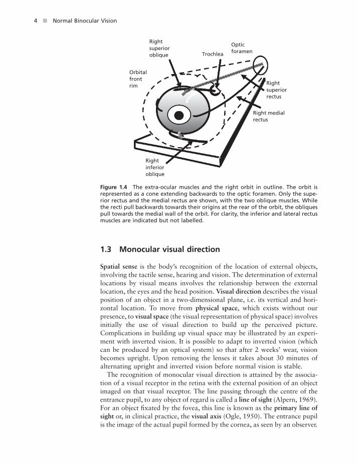
• Extra - ocular muscles to allow the object fi xated to be imaged on appropriate retinal areas of each eye (Fig. 1.4 ).
• Motor control systems to govern voluntary and refl ex eye movements – e.g. to maintain or vary fi xation. Also there has to be a method of correlating binocular sensory input and binocular motor function: motor correspondence .
• Further enhancement of binocular perception is obtained by the triangulation of objects observed using head and body movements and the addition of other, monocular, clues to the total visual perception.
Figure 1.2 The visual fi elds of the pigeon, showing a 24 - degree binocular fi eld, and a total fi eld of 340 degrees, mainly monocular (after Walls, 1942 ).
Binocular 24 degrees
Total 340 degrees
Figure 1.3 The human neural pathway for vision, from the retina to the visual cortex. LGN, lateral geniculate nucleus.
Lateral ventricle
Chiasma
Visual radiations curveforward then back fromLGN
LGN
Striatecortex
4 ■ Normal Binocular Vision
1.3 Monocular v isual d irection
Spatial sense is the body ’ s recognition of the location of external objects, involving the tactile sense, hearing and vision. The determination of external locations by visual means involves the relationship between the external location, the eyes and the head position. Visual direction describes the visual position of an object in a two - dimensional plane, i.e. its vertical and hori-zontal location. To move from physical space , which exists without our presence, to visual space (the visual representation of physical space) involves initially the use of visual direction to build up the perceived picture. Complications in building up visual space may be illustrated by an experi-ment with inverted vision. It is possible to adapt to inverted vision (which can be produced by an optical system) so that after 2 weeks ’ wear, vision becomes upright. Upon removing the lenses it takes about 30 minutes of alternating upright and inverted vision before normal vision is stable.
The recognition of monocular visual direction is attained by the associa-tion of a visual receptor in the retina with the external position of an object imaged on that visual receptor. The line passing through the centre of the entrance pupil, to any object of regard is called a line of sight (Alpern, 1969 ). For an object fi xated by the fovea, this line is known as the primary line of sight or, in clinical practice, the visual axis (Ogle, 1950 ). The entrance pupil is the image of the actual pupil formed by the cornea, as seen by an observer.
Figure 1.4 The extra - ocular muscles and the right orbit in outline. The orbit is represented as a cone extending backwards to the optic foramen. Only the supe-rior rectus and the medial rectus are shown, with the two oblique muscles. While the recti pull backwards towards their origins at the rear of the orbit, the obliques pull towards the medial wall of the orbit. For clarity, the inferior and lateral rectus muscles are indicated but not labelled.
Rightsuperior oblique Trochlea
Optic foramen
Rightinferioroblique
Rightsuperior rectus
Right medial rectus
Orbitalfrontrim

Introduction to Normal Binocular Vision ■ 5
The visual axis is more strictly defi ned as the external light ray that, after refraction by the optical system of the eye, will fall on the fovea (Freedman and Brown, 2008 ). The fovea is the retinal area that receives images from objects observed straight ahead. Visual acuity and colour perception are normally best at the fovea. When the object of regard is imaged on the fovea, the oculomotor system ceases to initiate any eye movement. The fovea is thus the retino - motor zero point, or retino - motor centre.
Disambiguation n ote: the term ‘ zero point ’ is also used in relation to retinal correspondence (see section 4.5 in Chapter 4 ).
Note: • In 1907 Maddox used the terms ‘ visual line ’ and ‘ fi xation line ’
(Maddox, 1907 ). • The visual axis must pass through the nodal point(s), and as there are
two nodal points in the eye situated 7.13 and 7.41 mm behind the corneal vertex, a single visual axis cannot strictly connect the fovea with the object of regard (Rabbetts, 2007 ; Harris, 2010 ). For simplicity hereafter the terms ‘ visual axis ’ and ‘ primary line of sight ’ are used synonymously, and this is indicated in the text.
• The visual axis is not (usually) the same as the optic axis of the eye, which is why the anterior corneal refl ection is not usually in the centre of the pupil (Fig. 1.5 ). The measurement of these axes is discussed by Dunne et al. , (2005) .
The primary line of sight (the visual axis) is said to have the principal visual direction , i.e. from the fovea to the object imaged on the fovea. All non - foveal retinal receptors have secondary visual directions . The angular value of a secondary visual direction is calibrated by reference to the primary visual direction. The general term ‘ line of sight ’ includes both primary and secondary visual directions. Non - foveal lines of sight are referred to as ‘ secondary ’ lines of sight, or ‘ lines of direction ’ (Cline et al. , 1980 ). Hereafter,
Figure 1.5 The visual, pupillary and optic axes. View of the human right eye from above, indicating the conventional directions of various axes relative to the route from the fi xation point to its retinal image, via the pupil, and the assumed nodal points. The pupillary axis lies between the other two axes.
Nasal
Temporal
Visual axis
Pupil centre Fixationpoint
Crystalline lens
Fovealimage
Ocular ‘centre’ of rotation
Region of nodal points
Approximate optical axis

6 ■ Normal Binocular Vision
‘ the line of sight ’ will refer to the primary line of sight, unless otherwise stated. Any number of objects situated on the same (primary or secondary) line of sight will stimulate the same receptor. This is the law of oculocentric direction : the direction of all these objects is the same and given by reference to the single eye involved. The law relates to the use of one eye only. So when the fovea of that eye re - fi xates on an object in a different direction, the oculocentric visual direction moves with it.
The recognition of visual direction by retinal receptors is called local sign : each retinal receptor sends a neuro - visual signal and encodes the direction in vertical and horizontal coordinates, but not the distance. Each retinal receptor – cerebral sensory unit has a unique ability to detect a particular direction. These signals are conveyed through the lateral geniculate nucleus to the visual cortex (Fig. 1.6 ). In other words, each retinal receptor is associ-ated with the particular direction from which it receives a stimulus. This association extends as far as the visual cortex: there is said to be retinotopic mapping of neurones in the visual system (Zeki and Shipp, 1988 ). This has been demonstrated in reverse by stimulating cortical neurones electrically. The subject sees a fl ash of light in the direction associated with the stimu-lated cortical neurone.
The local sign is the angular subtense between a retinal receptor ’ s second-ary visual direction and the primary visual direction of the fovea (Lotze, 1852 ). The high precision of local sign is a result of a cortical averaging process, which takes the mean of both spatial and temporal fl uctuations in
Figure 1.6 The visual system sensory and third nerve motor pathways. A schematic plan view of the visuum showing the location in the striate cortex of sensory input from the central and peripheral retina. The motor route from the third cranial nerve nuclei to the medial rectus muscles is also shown. CG, ciliary ganglion; LGN, lateral geniculate nucleus; MR, medial rectus.
Foveal fibres
LGN
Peripheralfibres via LGN
III
Foveal image
MR
CG
Introduction to Normal Binocular Vision ■ 7
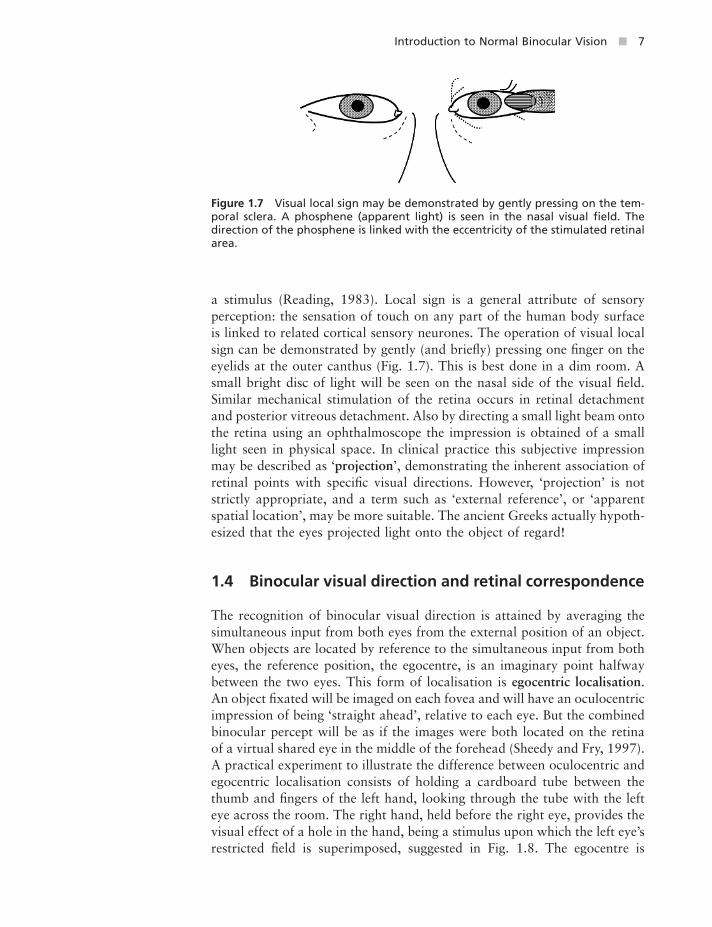
a stimulus (Reading, 1983 ). Local sign is a general attribute of sensory perception: the sensation of touch on any part of the human body surface is linked to related cortical sensory neurones. The operation of visual local sign can be demonstrated by gently (and briefl y) pressing one fi nger on the eyelids at the outer canthus (Fig. 1.7 ). This is best done in a dim room. A small bright disc of light will be seen on the nasal side of the visual fi eld. Similar mechanical stimulation of the retina occurs in retinal detachment and posterior vitreous detachment. Also by directing a small light beam onto the retina using an ophthalmoscope the impression is obtained of a small light seen in physical space. In clinical practice this subjective impression may be described as ‘ projection ’ , demonstrating the inherent association of retinal points with specifi c visual directions. However, ‘ projection ’ is not strictly appropriate, and a term such as ‘ external reference ’ , or ‘ apparent spatial location ’ , may be more suitable. The ancient Greeks actually hypoth-esized that the eyes projected light onto the object of regard!
1.4 Binocular v isual d irection and r etinal c orrespondence
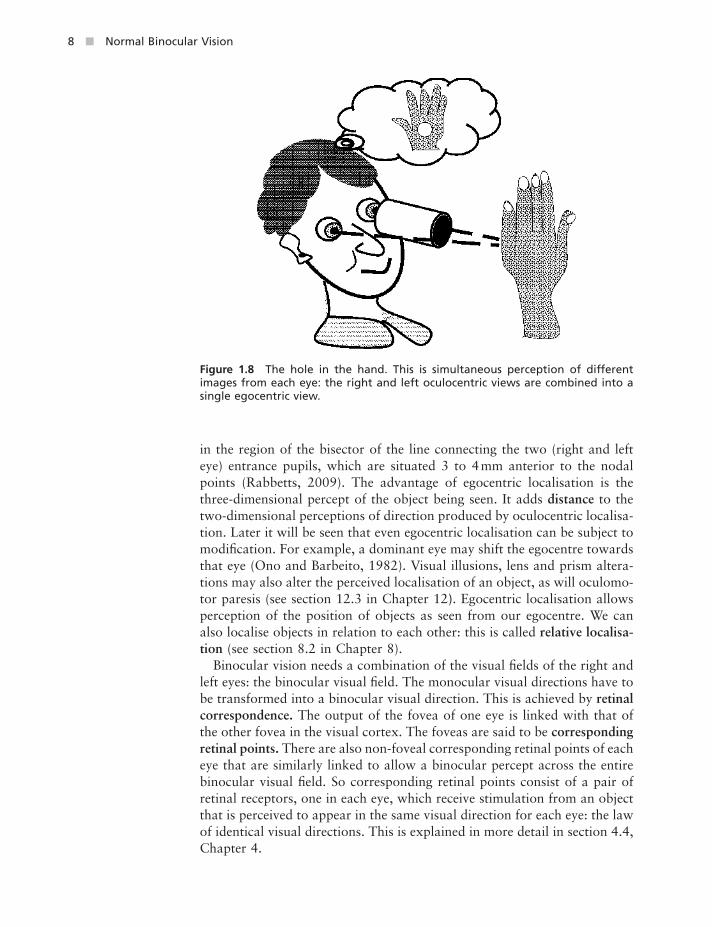
The recognition of binocular visual direction is attained by averaging the simultaneous input from both eyes from the external position of an object. When objects are located by reference to the simultaneous input from both eyes, the reference position, the egocentre, is an imaginary point halfway between the two eyes. This form of localisation is egocentric localisation . An object fi xated will be imaged on each fovea and will have an oculocentric impression of being ‘ straight ahead ’ , relative to each eye. But the combined binocular percept will be as if the images were both located on the retina of a virtual shared eye in the middle of the forehead (Sheedy and Fry, 1997 ). A practical experiment to illustrate the difference between oculocentric and egocentric localisation consists of holding a cardboard tube between the thumb and fi ngers of the left hand, looking through the tube with the left eye across the room. The right hand, held before the right eye, provides the visual effect of a hole in the hand, being a stimulus upon which the left eye ’ s restricted fi eld is superimposed, suggested in Fig. 1.8 . The egocentre is
Figure 1.7 Visual local sign may be demonstrated by gently pressing on the tem-poral sclera. A phosphene (apparent light) is seen in the nasal visual fi eld. The direction of the phosphene is linked with the eccentricity of the stimulated retinal area.
8 ■ Normal Binocular Vision
in the region of the bisector of the line connecting the two (right and left eye) entrance pupils, which are situated 3 to 4 mm anterior to the nodal points (Rabbetts, 2009 ). The advantage of egocentric localisation is the three - dimensional percept of the object being seen. It adds distance to the two - dimensional perceptions of direction produced by oculocentric localisa-tion. Later it will be seen that even egocentric localisation can be subject to modifi cation. For example, a dominant eye may shift the egocentre towards that eye (Ono and Barbeito, 1982 ). Visual illusions, lens and prism altera-tions may also alter the perceived localisation of an object, as will oculomo-tor paresis (see section 12.3 in Chapter 12 ) . Egocentric localisation allows perception of the position of objects as seen from our egocentre. We can also localise objects in relation to each other: this is called relative localisa-tion (see section 8.2 in Chapter 8 ).
Binocular vision needs a combination of the visual fi elds of the right and left eyes: the binocular visual fi eld. The monocular visual directions have to be transformed into a binocular visual direction. This is achieved by retinal correspondence. The output of the fovea of one eye is linked with that of the other fovea in the visual cortex. The foveas are said to be corresponding retinal points. There are also non - foveal corresponding retinal points of each eye that are similarly linked to allow a binocular percept across the entire binocular visual fi eld. So corresponding retinal points consist of a pair of retinal receptors, one in each eye, which receive stimulation from an object that is perceived to appear in the same visual direction for each eye: the law of identical visual directions. This is explained in more detail in section 4.4 , Chapter 4 .
Figure 1.8 The hole in the hand. This is simultaneous perception of different images from each eye: the right and left oculocentric views are combined into a single egocentric view.

Introduction to Normal Binocular Vision ■ 9
The effect of egocentric localisation is to produce a common subjective principal visual direction. This is sometimes referred to as the cyclopean eye effect. Cyclops was the giant in Greek mythology with a single eye in the middle of his forehead (Fig. 1.9 ). Binocular visual localisation is centred on the cyclopean eye. An object imaged on each fovea is seen binocularly in the primary common subjective visual direction (Fig. 1.10 ).
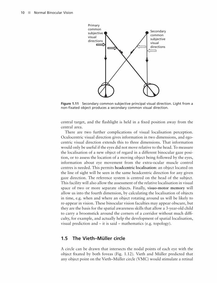
Similarly, for every non - foveal point in one eye there is a related point in the other eye, which shares the same visual direction, these two non - foveal points being corresponding retinal points. The object seen by the two cor-responding non - foveal points lies in a secondary common subjective visual direction, which is located by reference to the primary common subjective principal visual direction associated with the two foveas (Fig. 1.11 ). The existence of the common subjective principal visual direction can be dem-onstrated by masking a photographic fl ashlight to produce a vertical slit. One eye is covered, the centre of the vertical slit is fi xated and the fl ash is generated. Repeat with the other eye with the slit held horizontally and the fi rst eye occluded. The binocular after - image seen is a cross, demonstrating the common visual direction. This will work both for the foveas and the non - foveal corresponding points. In the latter case, the subject fi xates a
Figure 1.9 The effective human cyclopean view. The direction of the fi xated object seen with both eyes open is linked with a virtual eye position midway between the right and left eyes.
Figure 1.10 Primary common subjective principal visual direction. Light from an object stimulating both foveas produces a common visual direction.
Light from an objectimaged on each fovea
(Subjective impression)The 'primary impression’subjective principal visualdirection
10 ■ Normal Binocular Vision
central target, and the fl ashlight is held in a fi xed position away from the central area.
There are two further complications of visual localisation perception. Oculocentric visual direction gives information in two dimensions, and ego-centric visual direction extends this to three dimensions. That information would only be useful if the eyes did not move relative to the head. To measure the localisation of a new object of regard in a different binocular gaze posi-tion, or to assess the location of a moving object being followed by the eyes, information about eye movement from the extra - ocular muscle control centres is needed. This permits headcentric localisation : an object located on the line of sight will be seen in the same headcentric direction for any given gaze direction. The reference system is centred on the head of the subject. This facility will also allow the assessment of the relative localisation in visual space of two or more separate objects. Finally, visuo - motor memory will allow us into the fourth dimension, by calculating the localisation of objects in time, e.g. when and where an object rotating around us will be likely to re - appear in vision. These binocular vision faculties may appear obscure, but they are the basis for the spatial awareness skills that allow a 3 - year - old child to carry a broomstick around the corners of a corridor without much diffi -culty, for example, and actually help the development of spatial localisation, visual prediction and – it is said – mathematics (e.g. topology).
1.5 The Vieth – M ü ller c ircle
A circle can be drawn that intersects the nodal points of each eye with the object fi xated by both foveas (Fig. 1.12 ). Vieth and M ü ller predicted that any object point on the Vieth – M ü ller circle (VMC) would stimulate a retinal
Figure 1.11 Secondary common subjective principal visual direction. Light from a non - fi xated object produces a secondary common visual direction.
Secondarycommonsubjectivevisualdirections
Primarycommonsubjectivevisualdirections

Introduction to Normal Binocular Vision ■ 11
point on each eye, which would have the same angular subtense relative to each fovea. Thus the VMC is a theoretical model of the positions of objects in space, which are imaged on corresponding retinal points. Any point on this circle would be seen binocularly as a single object.
Note: some versions of the Vieth – M ü ller circle diagram use the eyes ’ entrance pupils or even the centres of rotation instead of the nodal points.
The VMC is used to describe the optical formation of images on the retina of each eye. The VMC concept assumes that corresponding retinal points are placed at regular and equal horizontal distances from the fovea of each eye. However, the measured locus of every point in space that actually stimulates corresponding retinal points for a particular binocular fi xation is called the horopter , and this will not be the same as the VMC (see Chapter 6 ).
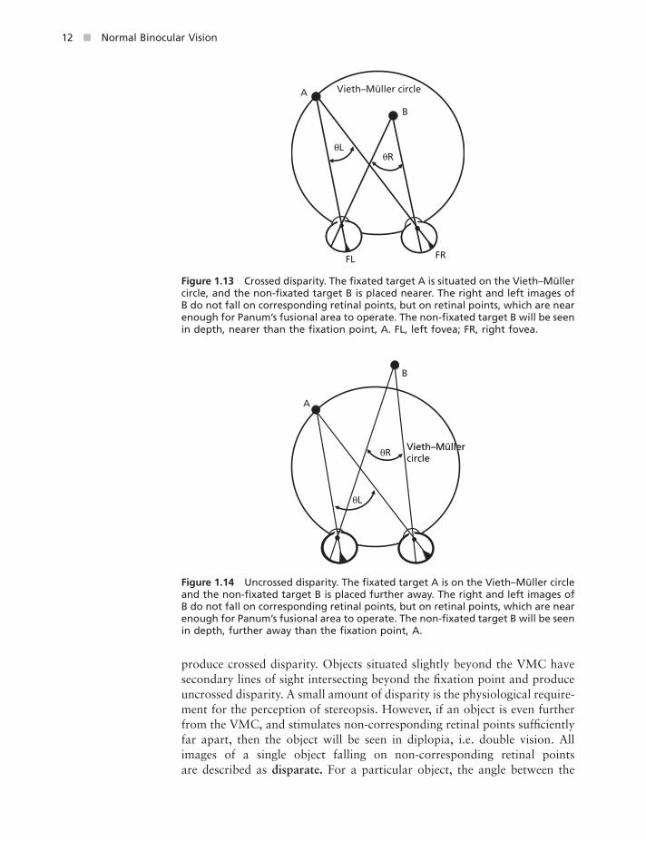
1.6 Horizontal r etinal b inocular d isparity
An object – let us call it object ‘ A ’ – whose image falls on corresponding retinal points of each eye will be seen as a single object. Where a second object ‘ B ’ situated on the same horizontal meridian as object ‘ A ’ , is imaged on non - corresponding retinal points in each eye, the percept will be that object ‘ B ’ is seen as nearer or further from object ‘ A ’ (Fig. 1.13 and Fig. 1.14 ). Where the second object is situated slightly closer than the VMC, its secondary lines of sight would intersect nearer than the fi xation point and
Figure 1.12 The Vieth – M ü ller circle (VMC; the basic form of the horopter). Three objects in space are imaged on the two retinas, each object forming images on corresponding ‘ points ’ (or areas). The geometry of the fi gure dictates that the angles shown are all equal to each other. The points through which the three lines pass in each eye are usually considered to represent the nodal points of the eyes, and fall on the VMC. However, opinions differ, some writers using the entrance pupils or even the assumed centres of rotation of the eyes. FL, left fovea; FR, right fovea.
B
CA
FL FR
12 ■ Normal Binocular Vision
produce crossed disparity. Objects situated slightly beyond the VMC have secondary lines of sight intersecting beyond the fi xation point and produce uncrossed disparity. A small amount of disparity is the physiological require-ment for the perception of stereopsis. However, if an object is even further from the VMC, and stimulates non - corresponding retinal points suffi ciently far apart, then the object will be seen in diplopia, i.e. double vision. All images of a single object falling on non - corresponding retinal points are described as disparate. For a particular object, the angle between the
Figure 1.13 Crossed disparity. The fi xated target A is situated on the Vieth – M ü ller circle, and the non - fi xated target B is placed nearer. The right and left images of B do not fall on corresponding retinal points, but on retinal points, which are near enough for Panum ’ s fusional area to operate. The non - fi xated target B will be seen in depth, nearer than the fi xation point, A. FL, left fovea; FR, right fovea.
Vieth–Müller circleA
B
θLθR
FL FR
Figure 1.14 Uncrossed disparity. The fi xated target A is on the Vieth – M ü ller circle and the non - fi xated target B is placed further away. The right and left images of B do not fall on corresponding retinal points, but on retinal points, which are near enough for Panum ’ s fusional area to operate. The non - fi xated target B will be seen in depth, further away than the fi xation point, A.
A
B
θL
θRVieth–MüllerVieth–Müllercircle circle Vieth–Müllercircle

Introduction to Normal Binocular Vision ■ 13
principal visual direction and the secondary visual direction in which the object is seen is called the subtense angle. The angular difference between the subtense angles of the right and left eyes is called the (horizontal) retinal binocular disparity (usually abbreviated to disparity ). Although the example given above was of objects on the same horizontal meridian, the actual orientation of the retinal binocular disparity may be horizontal, vertical or oblique. The value, i.e. the quantifi cation of the retinal binocular disparity, may be positive, negative or, for corresponding retinal points only, zero.
Horizontal retinal binocular disparity is the trigger for the perceptive faculty known as stereopsis , disparity sensitivity or binocular depth percep-tion (see True binocular depth perception in Chapter 11 ). The disparity must be enough to produce stereopsis, but not so large as to cause diplopia. For a three - dimensional object there are different amounts of horizontal retinal binocular disparity relating to different elements of the object, some being seen nearer and some further away than the part of the object fi xated by the foveas. So looking at the windscreen of an approaching car, the headlamps will be seen closer and the rear door further away. The windscreen would fall on the VMC; the headlamps would be within the VMC and the rear door beyond the VMC. The lines of sight for the headlamps would have crossed disparity , and those of the rear door would have uncrossed disparity.
Disambiguation n ote: all images of objects seen binocularly on the same meridian, which are situated closer or further than the VMC, will be dispa-rate. The term ‘ disparity ’ implies stereoscopic fusion, but the term ‘ dispa-rate ’ includes objects seen in diplopia, as well as those capable of stereoscopic fusion.
1.7 Vertical r etinal b inocular d isparity and c yclofusion
If a vertical line in physical space is imaged on the vertical meridians of each retina of a subject, the retinal meridians are corresponding meridians, and the line will be seen without any stereoscopic effect. This is because all the horizontal elements that make up the vertical images will have zero horizon-tal disparity. If the line in physical space is now tilted with the top towards (or away from) the subject, the image of the line will fall on non - vertical retinal meridians. Each eye will have a different side view of the physical line. It is possible to work out the angle ( D degrees) between the ocular non - vertical meridians, if the interpupillary distance (2 a in mm), and the distance from the eyes to the vertical line ( b ) are known, using the formula:
tan 2 tanD a b i= ×
where i is the inclination in degrees of the physical line towards the subject. The line in physical space will now be seen stereoscopically, as leaning towards (or away from) the subject. A discussion of the effect in this situation on cyclovergence and cyclofusion will be found in section 12.10 , Chapter 12 .

14 ■ Normal Binocular Vision
Vertical retinal disparities, together with horizontal disparities, allow cortical assessment of eye position (from the retinal data alone). However, the size of vertical disparities can be deduced from purely horizontal retinal disparity, because a vertical disparity adjusts the cortical receptive fi eld position of corresponding points to the next higher or lower row of hori-zontal cortical sensors. Directions of gaze and of vergence thus can be recovered from horizontal disparity information (Read and Cumming, 2006 ). Where a vertical disparity occurs in near vision, any vertical diplopia is normally controlled by vertical vergence, and perceptual ambiguities because of asymmetrical convergence are resolved by the vertical disparity analysis capacity of the visual system (Brautaset and Jennings, 2005 ).
1.8 Cortical b inocular d isparity
To complicate things a little, the actual arrangement of neural pathways from the retina to the visual cortex determines cortical ( receptive fi eld) binocular disparity , with zero disparity for single, non - stereoscopic, vision. It is possible for the visual cortex to adapt, producing single vision even where zero retinal binocular disparity is not present, as where a subject has an anisometropic spectacle correction producing unequal retinal images but has adapted to see an undistorted visual percept. Here there would be zero cortical binocular disparity despite non - zero retinal binocular disparity.
Chapter 1: Revision quiz
Complete the missing words, perhaps in pencil. Only look at the answer when you have really tried. It would be useful to look back at the text and then try all these questions again.
Binocular vision has the advantage of s_____________________ (1) over double vision. The subtle difference between right and left viewpoints allows d_____________________ (2) percep-tion, also called stereopsis. In addition, binocular vision allows visual summation, which imp_____________________ (3) binocular over monocular performance in a variety of ways.
Monocular visual direction allows the location of an object in t_____________________ (4) dimen-sions. Local sign is the angle between the direction of the fovea and the direction of a n_____________________ (5) - foveal receptor. Binocular visual direction is achieved by ret_____________________ (6) correspondence, the presence of which can be demonstrated by using af_____________________ (7) - images.
The theoretical model of the surface in physical space that locates objects that stimulate corresponding retinal points is called the V_____________________ – M_____________________ c_____________________ (8).
Objects that are almost but not quite stimulating corresponding retinal points produce horizontal retinal binocular dis_____________________ (9), which is the basis for stereopsis.
Answers (1) single; (2) depth; (3) improves; (4) two; (5) non; (6) retinal; (7) after; (8) Vieth – M ü ller circle; (9) disparity.