CHAPTER 1 INTRODUCTION - Shodhgangashodhganga.inflibnet.ac.in/bitstream/10603/17021/6/06_chapter...
35
1 CHAPTER 1 INTRODUCTION 1.1 GENERAL Stopping safely is one of the most important functions of the braking system in a motor cycle. Many electronic control systems have been developed for improving the safety of vehicle driving. For example, the anti lock braking system (ABS) was developed for improving the vehicle’s steer- ability and stability by preventing the wheel lock under critical circumstance such as slippery road condition during braking. So far various control strategies for the anti lock braking system (ABS) have been proposed by adopting proportional solenoid valve (Mauer 1995; Chinet et al., 1992; Drakunov et al., 1995). However, it is generally known that the proportional solenoid valve may produce unwanted fluctuation of the braking pressure during the anti lock braking system (ABS) operation and the braking force distribution under variable load is hard using the above said device. In a practical environment, the contrivance is unwelcome due to its complex design. Hence it is desirable to introduce an alternative actuation mechanism to overcome these drawbacks. Failure of the brake system will almost invariably result in property damage, personal injury, or even death. Consequently, a great deal of consideration has been given to improving the brake system. The problem of skidding reveals the one overwhelming weakness of all motor vehicle braking systems, namely, their strong dependence on the coefficient of adhesion between the tyre and the road and normal load on the wheel on which brake is applied. If for any reason the
Transcript of CHAPTER 1 INTRODUCTION - Shodhgangashodhganga.inflibnet.ac.in/bitstream/10603/17021/6/06_chapter...

1
CHAPTER 1
INTRODUCTION
1.1 GENERAL
Stopping safely is one of the most important functions of the
braking system in a motor cycle. Many electronic control systems have been
developed for improving the safety of vehicle driving. For example, the anti
lock braking system (ABS) was developed for improving the vehicle’s steer-
ability and stability by preventing the wheel lock under critical circumstance
such as slippery road condition during braking. So far various control
strategies for the anti lock braking system (ABS) have been proposed by
adopting proportional solenoid valve (Mauer 1995; Chinet et al., 1992;
Drakunov et al., 1995). However, it is generally known that the proportional
solenoid valve may produce unwanted fluctuation of the braking pressure
during the anti lock braking system (ABS) operation and the braking force
distribution under variable load is hard using the above said device. In a
practical environment, the contrivance is unwelcome due to its complex
design. Hence it is desirable to introduce an alternative actuation mechanism
to overcome these drawbacks. Failure of the brake system will almost
invariably result in property damage, personal injury, or even death.
Consequently, a great deal of consideration has been given to improving the
brake system. The problem of skidding reveals the one overwhelming
weakness of all motor vehicle braking systems, namely, their strong
dependence on the coefficient of adhesion between the tyre and the road and
normal load on the wheel on which brake is applied. If for any reason the

2
tyre momentarily loses its adhesion to the road while the brakes are applied,
the friction of the brakes against the drums or rotors locks the wheel solidly
and the tyre begins skidding across the road. In this condition, the braking
force of that wheel depends on the sliding friction between the tyre and the
road, which is much less than the static friction and normal load on the wheel.
Under wet or icy conditions, the sliding friction is reduced even further,
resulting in significantly longer stopping distances. Inspection of the axle
loads reveals that the rear axle load is reduced more than that associated with
front axle (increased) at higher decelerations due to load transfer effect and
the initial axle loads.
Braking force is produced due to the frictional force between the
tyre and the road surface and must be concentrated onto the front wheel for
driving stability. However, in many motor cycles the braking force needs to
be appropriately distributed between the front and the rear wheels if the load
in the rear wheels is added due to extra load at pillion of the motor cycle. By
doing this, the vehicle stability can be significantly increased. A proportional
valve is used for the braking force distribution between the front and the rear
wheels in the conventional brake system. The proportioning valve applies the
braking force uniformly to the front and the rear wheels according to
actuating force regardless of the increase of vehicle weight or dynamic weight
transfer effect during braking and cornering. Therefore, the amount of braking
force in the rear wheel is not increased continuously because the preset force
rate is applied to the front and rear wheels even though the rear wheel requires
greater braking force in accordance with the weight increase in the rear wheel.
The best condition in braking force distribution system is to keep
ideal braking force when the load of the axle is changed dynamically during
straight or corner braking. This effect makes the vehicle’s movement stable
and the braking operation of the rear wheel is able to use maximum friction

3
force between the tyre and the road surface. Figure 1.1 presents ideal curves
for the braking force distribution depending upon changes in vehicular weight
(Buschmann et al., 1993). As seen from the Figure1.1, the brake pressure of
the rear wheel should be appropriately adjusted according to the load
increment. The conventional system without brake force distribution supplies
braking force in a fixed rate to the front and the rear wheels regardless of any
changes in the vehicular weight. On the other hand, the braking force
distribution control system adjusts the braking force to the rear wheels
according to changes in vehicular weight to maximize braking effectiveness
of the rear wheel. Recently, Choi et al., (2008) presented the braking control
performance of a braking force distribution system featuring an
electrorheological (ER) valve pressure modulator. This system with a
controller for desired slip rate was realised through a hardware-in-the-loop
system (HILS) method.
Figure1.1 Ideal curves for braking force distribution
One of the new approaches to achieve the required control
characteristics for vehicle is to use a variable position caliper in the
motorcycle. When the caliper position is changed along the radial direction,

4
the effective brake disc radius which depends on the pillion load on the
motorcycle gets changed.
In the present research work, the braking force distribution system
is proposed to achieve the variable braking force between the road surface and
the tyre of the motorcycle. A micro controller is designed to actuate a stepper
motor to vary the position of caliper in order to vary the effective disc radius,
based on a load cell signal given to the micro controller. When the pillion
load is added on the two-wheeler, the microcontroller sets the optimum
caliper position for the corresponding pillion load on the motorcycle, keeping
the rider weight and hydraulic brake line pressure constant. The stopping
distance is measured with and without changing the effective disc radius. If
the brake disc radius is changed based on the pillion load, the stopping
distance gets reduced when compared with conventional braking system
(Effective disc radius is same) in the motorcycle.
1.2 OBJECTIVES AND SCOPE OF THE RESEARCH
To improve the safety of the two-wheeler.
To reduce the stopping distance of the two-wheeler.
To improve stability of the two-wheeler by preventing rear
wheel skidding.
So far the braking force is controlled in the dynamic condition,
i.e., after applying the brake the payload is being sensed and
based on the load, the braking force is varied. But in this work
payload is sensed whenever the vehicle is loaded and the
braking force (after applying brake) is varied based on the load
[by changing the effective radius of brake disc which is defined
as the radial distance measured from the disc center of rotation to

5
the center of pressure of caliper pistons (brake pad centerline)] and
it does not matter whether the brake is applied or not. The
system starts working (caliper starts to move and sets the brake
pads to the effective disc radius which is determined based on
pillion load on the motorcycle) when there is a variation in the
payload on the pillion of the motorcycle even when the vehicle
is in static condition. For example, ABS starts to work if the
brakes are applied and this is the primary condition for the
working of ABS system. Hence the time taken for sensing load
and brake actuating time can be reduced while applying brakes.
This approach is like ‘prevention is better than cure’. The brake
proportioning also depends on the front tyre loading. But during
the sudden deceleration dynamic normal reaction on the front
tyre increases and on the rear tyre it decreases. Hence the rear
tyre locks-up earlier than the front brake, due to the decrease in
dynamic normal reaction on the rear tire if both the brakes are
applied at the same time. So in this research work, VBF
(Variable braking force) system is implemented in the rear tyre.
Also this system is not active system and is only proportioned
/activated during start up.
1.3 LITERATURE REVIEW
Seung Bok Choi et al., (2008) developed a controllable
electrorheological (ER) valve system and applied to vehicle anti lock braking
system (ABS) in order to control braking force distribution. A cylindrical
electrorheological (ER) valve was designed and its pressure controllability
was experimentally confirmed. A hydraulic booster is developed in order to
amplify the field-dependent pressure drop obtained from the
electrorheological (ER) valve and subsequently derived the governing

6
equation of the rear wheel model. In this work, a sliding mode controller was
also developed to achieve the desired slip rate. In addition, computer
animation results for the braking performance under both unladen and laden
cases were presented.
Huei Peng et al., (1996) studied the optimal tyre force distribution
to maximize acceleration/deceleration of a four-wheel vehicle during
cornering. The objective of this research was to investigate the improvement
that could be expected from the implementation of different vehicle steering
and driving mechanisms. The optimization involved equality and inequality
constraints which were solved by nonlinear programming techniques.
Shinji Matsumoto et al., (1992) performed the experimentation and computer simulation about the influence of vehicle dynamics of braking force distribution on four wheels. The analytical results indicated that a suitable braking force distribution control method could improve handling and stability during braking. A new braking force distribution control strategy, using a steering wheel angle feed forward function and a yaw velocity feedback function was found to improve vehicle dynamic behavior.
Hans-Christof Klein et al., (1984) studied on decisive importance that needs to be attached to the optimum braking force distribution in today’sand in the future scenario. This work dealt with an introduction of anti-locking controlled brake systems, detailed dealing with the layout principles and the factors influencing them, the conventional brake force distribution, conditioned by the wheel brakes, as well as its dispersion due to friction coefficient variations. A short survey of hydraulic pressure valve systems followed by adaptive brake force distribution principle had been reported in this work. A discussion of the control ranges of the anti-locking systems, depending on the actual brake force distribution was also presented in this work.

7
Yimin Gao et al., (2001) developed an electronically controlled braking system for electric vehicles (EV) and hybrid electric vehicles (HEV) which integrated regenerative braking, automatic control of the braking forces of the front and the rear wheels and wheels antilock function together. In this work, it had been designed, when failure occurred in the electric system, the braking system would function as a conventional man-actuated braking system. Control strategies for controlling the braking forces on the front and the rear wheels, regenerative braking and mechanical braking forces had also been developed. The antilock performance of the braking system had been simulated. It had been reported that significant amount of energy was recovered while the braking performance of the vehicle was perfect.
Buschmann et al., (1993) developed electronic brake force distribution (EBD) as sub-system of antilock braking system (ABS) to control the effective adhesion utilization on the rear wheels. In this work, the pressure of the rear wheels was approximated to the ideal brake force distribution in partial braking operation. Modification of conventional brake system in the direction of rear axle over braking and the components of the antilock braking system (ABS) were used in this work.
Chin et al., (1992) reported the use of an electromagnetic brake as supplementary retardation equipment, in which the friction brakes could used less frequently and therefore practically never reached high temperatures. The brake linings thus have a longer life span, and the potential "brake fade" problem can be avoided. A new mathematical model for electromagnetic brakes was proposed to describe their static characteristics (angular speed versus brake torque). The performance of the new mathematical model was found to be better than the other three models available in the literature in a least-square sense. A software program was also written in MATLAB to code different brake characteristics (both static and dynamic) and their performance was evaluated in different road scenarios.

8
Kim et al., (2007) proposed vehicle stability control logic for a four-wheel-drive hybrid electric vehicle using the regenerative braking of the rear motor and an electro hydraulic brake (EHB). A genetic algorithm was used to obtain the optimal brake torque distribution between the regenerative braking and the EHB torque. The genetic algorithm calculates the optimal regenerative braking torque and the optimal EHB torque for the given inputs of the desired yaw moment and road friction coefficient. Based on the optimal brake torque distribution, the vehicle stability control logic proposed generates the desired direct yaw moment to compensate the errors of the side-slip angle and yaw rate by a fuzzy control algorithm corresponding to the rider’s steering angle and vehicle velocity.
Peter Frank et al., (2000) presented a control algorithm that controlled the brake forces of a two-axle road vehicle in order to achieve equal slips on the wheels. This slip control algorithm operated in the domain of small slip values, where the anti lock braking system (ABS) was inactive. In case of successful control, the wheels reached the limit of adhesion at the same instant. This was found to result in a later activation of the anti lock braking system (ABS) and higher achievable deceleration. Measurements on a two-axle lorry were also included.
Johnston et al., (2005) stated that in recent years, the automotive
industry has seen a rapid decrease in product development cycle time and a
simultaneous increase in the variety of vehicles offered in the marketplace.
These trends require a rigorous yet efficient systems engineering approach to
the development of automotive braking systems. This paper provides an
overview of an objective process for developing and predicting vehicle-level
brake performance through an approach using both laboratory subsystem
testing and math modeling.
Nantais et al., (2008) developed a mathematical model to predict
normal load at each tyre and incorporated into a high fidelity vehicle model.

9
Brake pressure was distributed according to the predicted loads. A series of
simulations were conducted using the model to investigate stopping distances
under various conditions, vehicle stability during extreme obstacle avoidance
manoeuvres, and impact on rider steer effort. The results showed that active
brake proportioning (ABP) could potentially provide significant benefits for
both performance and safety.
Maron et al., (1997) stated that Continental Automotive Systems
started the development of an electromechanical brake-by-wire system (EMB)
in 1995. A major part of the development deals with the control of the brake
actuator. For the development of control algorithms a special test stand was
built. It consisted of the seat capsule, the actuator, and the personal computer
(PC)-based electronic control unit. As the electronic unit also performs a real
time vehicle and actuator simulation, a complete Hardware-in-the-Loop
system supports simultaneous engineering within this project. This paper
describes the Hardware-in-the-Loop development system and shows first results obtained in an early state of the development process.
Piotr Grzes et al., (2009) investigated the temperature fields of the
solid disc brake during short, emergency braking. The standard Galerkin
weighted residual algorithm was used to discrete the parabolic heat transfer
equation. The finite element simulation for two-dimensional model was
performed due to the heat flux ratio constantly distributed in circumferential
direction. Two types of disc brake assembly with appropriate boundary and
initial conditions were developed. The results of calculations for the
temperature expansion in axial and radial directions were presented. The
effect of the angular velocity and the contact pressure evolution on
temperature rise of disc brake was investigated. It was found that the
presented finite element technique for two-dimensional model with particular
assumption in operation and boundary conditions validated the achievements
in this field sofar.

10
Mansour Hadji Hosseinlou et al., (2012) explained that one of the
most important factors in reducing traffic accidents is to keep safe distance
between vehicles. The minimum safe distance depends on many factors such
as the riders’ ability to react in accident, the vehicle braking system, the
condition of the tyres, the corresponding frictional forces provided by the
tyres, the speed of vehicles, and many other factors. The main purpose of this
study is to evaluate the above mentioned factors and obtain a relationship
between speed and the so called minimum safe distance. In this study “Gim &
Nikravesh” and “Sakai” models have been used in order to calculate the
braking system force in each tyre, using two- wheel equivalent model to
calculate the braking force of vehicles and dynamic relations are used to
calculate safe stopping time and distance between the vehicles. Also the
comparison of the minimum calculated safe distance with the relations
delivered in Europe, Iran, and British Codes are investigated. In this study,
safe stopping distance software has been introduced in order to calculate safe
stopping distance based on different conditions. This software is designed and
compiled by Delphi programming environment and includes testing different
hypotheses for the rear and the front tyres, calculating details of braking
process such as stopping distance and stopping time, separating reflection
distance and dynamic stopping distance, simulation of the stop process 3
seconds before confronting danger and finally drawing graphs related in the
desired position. There is also a presentation of a recommendable formula in
order to calculate the amount of safe distance for the two cases of ordinary
braking system and antilock braking system (ABS) which covers the four
situations of dry, wet, snowy, and icy positions.
Yesim Oniz et al., (2009) explained that the control of an antilock
braking system (ABS) is a difficult problem due to its strongly non-linear and
uncertain characteristics. To overcome this difficulty, the integration of grey
system theory and sliding-mode control was proposed. This way, the

11
prediction capabilities of the former and the robustness of the latter were
combined to regulate optimal wheel slip depending on the vehicle forward
velocity. The design approach described was novel, considering that a point,
rather than a line, was used as the sliding control surface. The control
algorithm was derived and subsequently tested on a quarter vehicle model.
Encouraged by the simulation results indicating the ability to overcome the
stated difficulties with fast convergence, experiments were carried out in a
laboratory setup. The results obtained indicated the potential of the approach
in handling difficult real-time control problems.
Gergely et al., (2008) has stated that nowadays more and more
papers are written about Active Anti Roll Bars (AARB). These systems are
usually designed for vehicles with high center of gravity, and their purpose is
to change the roll stiffness of the vehicle, thus preventing a potential roll over.
In the present paper the use of AARB was analyzed from a different
perspective. An actuator was presented which allowed the proper control of
the vehicle's yaw stability. First, the basic vehicle dynamic laws were
described to show why and how it was possible to control the handling of the
car, with the different stiffness on the front and the rear anti roll bars. It was
followed by the description of the applied vehicle model, which helped to
analyze the effects of the ARB parameters. Simulated tests were presented,
and they showed how the over- and understeer characteristics of the car varied
as the ARB parameters were modified. Finally some basic conclusions were
drawn about the applicability of the possible control laws for such system.
Jaehoon Lee et al., (2008) explained that the most of reference
models for chassis controls usually had low level degree of freedom like a
bicycle model. However, these models included some different value in real
vehicle motion and had a difficulty to adapt new technology. In addition, it
was not good for real time that very high level degree of freedom like multi

12
body dynamic analysis programs because of their long solving time. So an
adaptive full vehicle dynamic model was developed that had 14 degrees of
freedom with theoretical equations and experimental data.
Kang et al., (2012) presented a modeling technique for representing
a non-linear hysteretic behavior of a leaf spring used for a commercial
vehicle. This leaf spring model was used for a full vehicle model to analyze
ride and handling characteristics of a commercial vehicle. The leaf spring was
modeled using three links and shackle components. These components were
assumed to be rigid in MSC.ADAMS. The links were connected by revolute
joints, and at the joints torsional springs, dampers and friction elements were
used to represent the hysteretic characteristics of leaf springs due to friction
between the leaves. The parameters were adjusted to fit the static and the
dynamic characteristics of the leaf spring. The hysteretic curves from the
simulations were compared with those from the test. The comparison between
the experiments and simulations showed a relatively good agreement in force-
displacement domain. MSC.ADAMS was used for manoeuvring simulations
of a commercial vehicle. Developed leaf spring model was adopted to a full
vehicle model for simulations. The dynamic characteristics of a full vehicle
model with leaf springs were analyzed in several simulations. The ride
characteristics of a full vehicle model were simulated in the bump run
manoeuvres, within the handling characteristics simulated in the J-turn
maneuver and the double lane-change maneuver. Simulation results showed
that the hysteretic behaviours of leaf springs were well reflected. The vehicle
ride and handling characteristics were analyzed in frequency and time domain
using simulation results. The results of the ride and handling simulation were
compared with the test results.
Kliasuovich Siarhei et al., (2004) proposed a research that was done
for a bus (28 passengers capacity) and consisted of the following parts:

13
Dynamical ADAMS model.
ESP algorithm in MATLAB/Simulink 6.5.
3D-model of bus body in Unigraphics software.
The virtual simulation allowed the investigation in the main
characteristics for the traction and braking modes of vehicle movement. The
created complex model gave the possibility for integrated analysis of bus
dynamics.
Meijaard et al., (2007) presented canonical linearized equations of
motion for the Whipple bicycle model consisting of four rigid laterally-
symmetric ideally-hinged parts: two wheels, a frame, and a front assembly.
The wheels were also axisymmetric and made ideal knife-edge rolling point
contact with the level ground. The mass distribution and geometry were
otherwise arbitrary. This conservative non-holonomic system had a
7-dimensional accessible configuration space and three velocity degrees of
freedom parameterized by rates of frame lean, steer angle, and rear-wheel
rotation. The terms were constructed in the governing equations methodically
for easy implementation. The equations were suitable for say, the study of
bicycle self-stability. These equations were derived by hand in two ways and
also checked against two non-linear dynamics simulations. In the century-old
literature several sets of equations fully agreed with those here and several did
not. Two benchmarks provided test cases for checking alternative
formulations of the equations of motion or alternative numerical solutions.
Further, the results here could serve as a check for general-purpose dynamics
programs. For the benchmark bicycles the Eigen values were calculated (the
roots of the characteristic equation) and the speeds at which bicycle lean and
steer are self-stable, confirming the century-old result that this conservative
system could have asymptotic stability.

14
Jimenez Felipe et al., (2004) explained that improvements in future
vehicles look for increasing levels of safety; consequently, among other
aspects, the dynamic behaviour of the vehicle represents a relevant factor
influencing the safety. It is important for the rider to predict the response of
the vehicle while he manoeuvers, therefore any improvement to be introduced
that helps in such a manner should be studied from the dynamics point of
view. This paper describes a methodology to obtain the most relevant
parameters of a vehicle and a systematic method to prepare tests and to deal
with the data provided by advanced instrumentation (e.g. gyroscopic platform,
optical distance sensors, and rotating wheel dynamometer) in order to validate
vehicle models or to study experimentally the complete dynamics of the
vehicle. It also included the application of the methodology to real data
resulting of tests in a vehicle.
Grzegorz Litak et al., (2008) explained that the Melnikov criterion
is used to examine a global homoclinic bifurcation and transition to chaos in
the case of a quarter car model excited kinematically by the road surface
profile. By analyzing the potential an analytic expression is found for the
homoclinic orbit. By introducing an harmonic excitation term and damping as
perturbations, the critical Melnikov amplitude of the road surface profile is
found, above which the system can vibrate chaotically.
Gundogdu et al., (2007) presented an optimization of a four-
degrees-of-freedom quarter car seat and suspension system using genetic
algorithms to determine a set of parameters to achieve the best performance of
the rider. Since the health of the rider is as important as the stability of the car,
the desired objective is proposed as the minimization of a multi objective
function formed by the combination of not only suspension deflection and
tyre deflection but also the head acceleration and Crest Factor (CF), which is
not practiced as usual by the designers. The optimization results are compared

15
through step and frequency responses of the seat and suspension system for
the optimum and currently used suspension systems. Comparatively better
results are obtained from the optimized system in terms of resonance peaks,
CF, and vibration dose value. The concept and the ideas set forth in this work
are directly applicable to both the car suspension and the seat design in
industry.
Naik et al., (2011) examined dynamical behavior of a non-linear oscillator with a symmetric potential that modeled a quarter-car forced by the road profile. The primary, super harmonic, and sub harmonic resonances of a harmonically excited non-linear quarter-car model with linear time delayed active control were investigated. The method of multiple scales was utilized to obtain first order approximation of response. The influence of delay in the system was focused. This naturally gave rise to a Delay Deferential Equation (DDE) model of the system. The effect of time delay and feedback gains of the steady state responses of primary, super harmonic, and sub harmonic resonances were investigated. By means of Melnikov technique, necessary condition for onset of chaos resulting from homoclinic bifurcation was derived analytically. A method was described to identify the critical forcing function and time delay above which the system became unstable. It was found that proper selection of time delay showed optimum dynamical behaviour. The accuracy of the method was obtained from the fractal basin boundaries.
Kuznetsov et al., (2011) derived a Human–Vehicle–Road (HVR) model, comprising a quarter-car and a biomechanical representation of the rider, was employed for the analysis. Differential equations were provided to describe the motions of various masses under the influence of a harmonic road excitation. These equations were, subsequently, solved to obtain a closed form mathematical expression for the steady-state vertical acceleration measurable at the vehicle–human interface. The solution made it possible to find optimal parameters for the vehicle suspension system with respect to a

16
specified ride comfort level. The quantitative definition given in the ISO 2631 standard for the ride comfort level was adopted in this paper for the optimization procedure. Numerical examples, based on actually measured road profiles, were presented to prove the validity of the proposed approach and its suitability for the problem at hand.
Grzegorz Litak et al., (2009) explained that the Melnikov criterion
was used to examine a global homoclinic bifurcation and transition to chaos
in the case of a quarter car model excited kinematically by a road surface
profile consisting of harmonic and noisy components. By analyzing the
potential an analytic expression was found for the homoclinic orbit. The road
profile excitation including harmonic and random characteristics as well as
the damping were treated as perturbations of a Hamiltonian system. The
critical Melnikov amplitude of the road surface profile was found, above
which the system could vibrate chaotically. This transition was analyzed for
different levels of noise and illustrated by numerical simulations.
Huseyin Akcay et al., (2005) used a quarter-car model to study the
response of the vehicle to profile imposed excitation with randomly varying
traverse velocity and variable vehicle forward velocity. Root-mean square
response of the vehicle to white and colored noise velocity road inputs was
analyzed. In the latter case, a recently developed subspace-based
identification algorithm was used to design a linear shape filter with output
spectrum matching the measured road spectrum. The linear shape filter was
used in constructing charts that illustrated the trade-offs among the passenger
comfort, the road-holding, and the suspension travel as functions of the
vehicle forward velocity.
Narayanan et al., (2009) explained that a control of the stationary
random response of a two degree of freedom (DOF) quarter-car vehicle model
with non-linear passive elements traversing a homogenous rough road with

17
sky-hook damper control strategy was considered. The sky-hook damper
control strategy was realized through a feedback control scheme. The
parameters of the sky-hook damper were optimally determined by equating
the control force of the feedback system to that obtained by Linear Quadratic
Regulator (LQR) control in a mean square equivalence sense. The non-linear
suspension was of hysteretic type and modeled by the Bouc–Wen model. The
equivalent linearization method was used to linearize the system and the
stochastic optimal control LQR theory was applied to the equivalent linear
system. Results showed the enhanced performance of feedback control based
on sky-hook to levels of performance of LQR control which were also
verified by Monte Carlo simulation.
Siewe Siewe et al., (2010) explained that stability and the steady states of the transverse motion of a quarter-car model excited by the road surface profile with non-symmetric potential were investigated. Initially, a set of slow-flow equations was derived using the method of multiple-time scales directly to the governing equation, governing the amplitudes and phases of approximate long time response of these oscillators, by applying an asymptotic analytical method. Determination of several possible types of steady-state motions was then reduced to solution of sets of algebraic equations. For all these solution types, appropriate stability analysis was also performed. In the second part of the study, this analysis was applied to an example mechanical system. First a systematic search was performed, revealing effects of system parameters on the existence and stability properties of periodic motions. Frequency-response as well as forced-response diagrams were presented and attention was focused on understanding the evolution and interaction of the various solution branches as the external forcing and non-linearity parameters were varied. Finally, numerical integration of the equations of motion demonstrated that the system exhibited period-doubling bifurcation or chaotic response for some parameter combinations.

18
Patrice Masson et al., (2012) presented a methodology for the cancellation of road noise, from the analysis of vibration transmission paths for an automotive suspension to the design of an active control system using inertial actuators on a suspension to reduce the vibrations transmitted to the chassis. First, experiments were conducted on a Chevrolet Epica LS automobile on a concrete track to measure accelerations induced on the suspension by the road. These measurements were combined with experimental Frequency Response Functions (FRFs) measured on a quarter-car test bench to reconstruct an equivalent three dimensional force applied on the wheel hub. Second, FRFs measured on the test bench between the three-dimensional driving force and forces at each suspension/chassis is linkage were used to characterize the different transmission paths. so vibration energy to the chassis. Third, an experimental model of the suspension was constructed to simulate the configuration of the active control system, using the primary(disturbance) FRFs and secondary (control) FRFs also were measured on the test bench. This model was used to optimize the configuration of the control actuators and to evaluate the required forces. Finally, a proto type of an active suspension was implemented and measurements were performed in order to assess the performance of the control approach.A4.6d B attenuation on transmitted forces was obtained in the50–250Hz range.
Narayanan et al., (1998) considered an active control of the time varying response to a stationary random excitation of a two-degree-of-freedom vehicle model with non-linear passive suspension elements .The method of equivalent linearization was used to derive the equivalent linear model and the optimal control laws were obtained by using stochastic optimal control theory based on full state information. Velocity squared damping and hysteresis type of stiffness non-linearities were considered. The performance of active suspensions with non-linear passive elements was found to be superior to the corresponding passive suspension systems. As a check on the accuracy of the equivalent linearization technique a Monte Carlo simulation
19
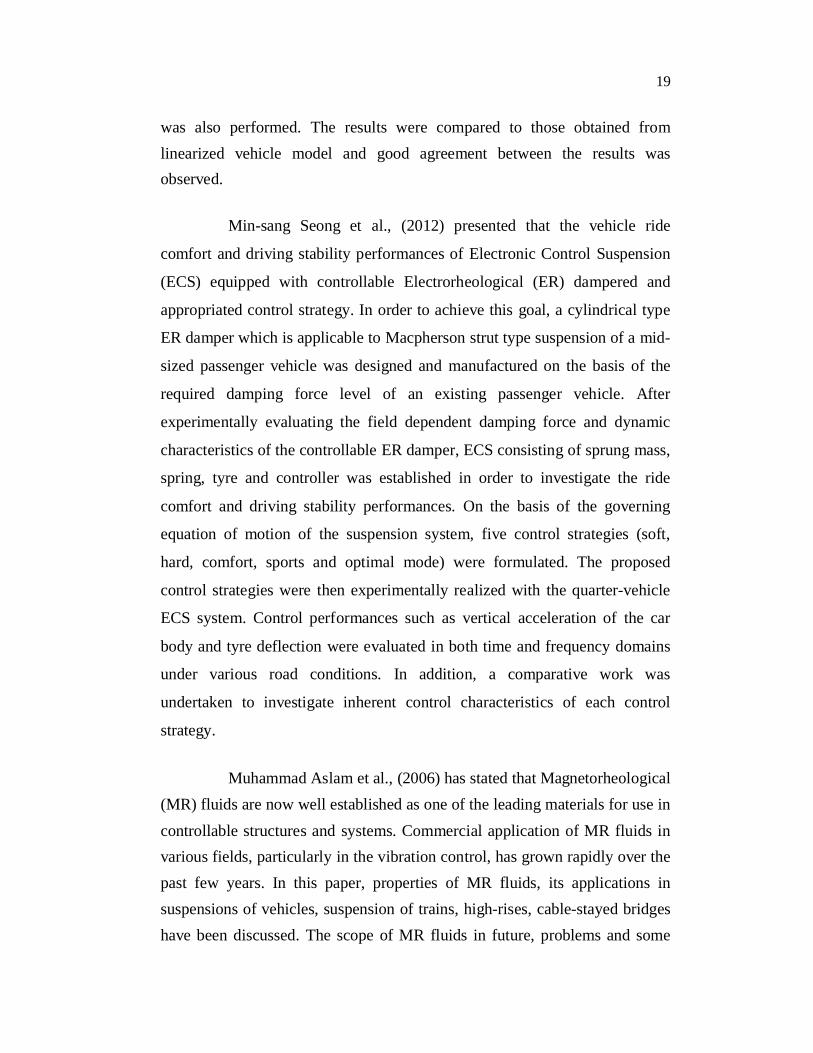
was also performed. The results were compared to those obtained from linearized vehicle model and good agreement between the results was observed.
Min-sang Seong et al., (2012) presented that the vehicle ride
comfort and driving stability performances of Electronic Control Suspension
(ECS) equipped with controllable Electrorheological (ER) dampered and
appropriated control strategy. In order to achieve this goal, a cylindrical type
ER damper which is applicable to Macpherson strut type suspension of a mid-
sized passenger vehicle was designed and manufactured on the basis of the
required damping force level of an existing passenger vehicle. After
experimentally evaluating the field dependent damping force and dynamic
characteristics of the controllable ER damper, ECS consisting of sprung mass,
spring, tyre and controller was established in order to investigate the ride
comfort and driving stability performances. On the basis of the governing
equation of motion of the suspension system, five control strategies (soft,
hard, comfort, sports and optimal mode) were formulated. The proposed
control strategies were then experimentally realized with the quarter-vehicle
ECS system. Control performances such as vertical acceleration of the car
body and tyre deflection were evaluated in both time and frequency domains
under various road conditions. In addition, a comparative work was
undertaken to investigate inherent control characteristics of each control
strategy.
Muhammad Aslam et al., (2006) has stated that Magnetorheological (MR) fluids are now well established as one of the leading materials for use in controllable structures and systems. Commercial application of MR fluids in various fields, particularly in the vibration control, has grown rapidly over the past few years. In this paper, properties of MR fluids, its applications in suspensions of vehicles, suspension of trains, high-rises, cable-stayed bridges have been discussed. The scope of MR fluids in future, problems and some

20
suggestions have also been presented. Finally, effectiveness of MR fluids in vibration control of marine diesel engine through experiment has been briefly discussed.
Kum-Gil Sung et al., (2011) evaluated the performance of a
quarter-vehicle magnetorheological (MR) suspension system with respect to
different tire pressure. In order to achieve this goal, controllable MR damper
that satisfies design specifications for a midsized commercial passenger
vehicle was designed and manufactured based on the optimized damping
force levels and mechanical dimensions. After experimentally evaluating the
field-dependent characteristics of the manufactured MR damper, the quarter-
vehicle suspension system consisting of sprung mass, spring, tyre and the MR
damper was constructed in order to investigate the ride comfort. After
deriving the equations of the motion for the proposed quarter-vehicle MR
suspension system, vertical tyre stiffness with respect to different tire pressure
was experimentally identified. The skyhook controller was then implemented
for the realization of quarter-vehicle MR suspension system. Ride comfort
characteristics such as vertical acceleration root mean square (RMS) and
weighted RMS (WRMS) of sprung mass were evaluated under bump and
random road conditions using a quarter-vehicle test facility.
Lee et al., (2011) discussed that since the invention of automobiles,
the need to know the braking performance of vehicles has been
acknowledged. However, because there are numerous design variables as well
as nonlinearities in the braking system, it is difficult to predict the
performance accurately. A computational program is developed to estimate
the braking performance numerically. This synthetic braking performance
program accounts for pedal force, pedal travel and deceleration of braking
parts, such as master cylinder, booster, valve, brake pad, rotor, and hoses. To
improve the accuracy of program, a semi-empirical model of a braking system

21
is introduced by using the empirical test data of pad compression, hose
expansion and the friction coefficient between the pad and rotor. The
accuracy of the estimation is evaluated by comparing it with the actual vehicle
test results. The developed program is easy for the brake system engineers to
manipulate and it can be used in the development of new vehicles by
incorporating the graphical presentations.
Piotr Grzes et al., (2011) studied the evaluation of an impact of
convective mode of heat transfer on the thermal behaviour of a disc brake
system during repetitive braking process with the constant velocity using fully
three-dimensional finite element model. The transient thermal analysis to
determine the temperature distributions on the contact surface of a disc brake
was performed. The issue of non-uniform frictional heating effects of mutual
slipping of a disc over fixed pads was tested using finite element (FE) models
with the several possible to occur in automotive application heat transfer
coefficients. To have a possibility of comparison of the temperature
distributions of a disc during cyclic brake application, the energy transformed
during the time of every analyzed case of braking process and the subsequent
release periods was kept the same. The time stepping procedure was
employed to develop moving heat source as the boundary heat flux acting
interchangeably with the convective cooling terms. The difficulties accounted
for the accurate simulation of heating during spin of the rotor were omitted by
the use of the code, which enabled shaping curves responsible for the thermal
flux entering the disc at subsequent moments of time. The resulting evolution
of temperature on the friction surface revealed a wide range of variations,
distinguishing periods of heating and cooling states. It was established that
during single braking the convective cooling has insignificant influence on the
temperature distributions of a disc brake, consequently was not able to
prevent overheat problem. However, the brake release period after the braking

22
operation, when the velocity of the vehicle remains on the same level, results
in considerable decrease of temperature.
Ali Belhocine et al., (2012) explained that the braking is a process
which converts the kinetic energy of the vehicle into mechanical energy
which must be dissipated in the form of heat. During the braking phase, the
frictional heat generated at the interface disc-pads can lead to high
temperatures. This phenomenon is even more important than that the
tangential stress as well as the relative sliding speeds in contact. is important.
The objective of this study is to analyze the thermal behaviour of the full and
ventilated brake discs of the vehicles using computing code ANSYS. The
modeling of the temperature distribution in the disc brake is used to identify
all the factors and the entering parameters concerned at the time of the
braking operation such as the type of braking, the geometric design of the disc
and the used material. The results obtained by the simulation are satisfactory
compared with those of the specialized literature.
Piotr Grzes et al., (2011) studied and compared the temperature
distributions caused by mutual sliding of two members of the disc brake
system basing on two- and three-dimensional FE modeling techniques and
complexity of the phenomenon. The first step of the analysis was based on the
previously developed model where the intensity of heat flux was assumed to
be uniformly distributed on the friction surface of disc during braking process,
and the heat was transferred exclusively in axial direction, whereas during the
second, the three-dimensional rotor was subjected to the non-axisymmetric
thermal load to simulate realistic thermal behaviour of the brake action.
Operation conditions, thermo-physical properties of materials and dimensions
of the brake system were adopted from the real representation of the braking
process of the passenger vehicle. Arbitrarily selected four values of the
velocities at the moment of brake engagement were applied to the models so

23
as to investigate their influence on the obtained solutions of the temperature
evolutions on the contact surface of the disc volume referring to two separated
finite element analysis. The large amount of heat generated at the pad/disc
interface during emergency braking indisputably evoked non-uniform
temperature distributions in the domain of the rotor, whereas the pad element
was constantly heated during mutual sliding. The obtained results of the
original code of three dimensional modeling technique implemented to the
conventional FE software revealed high agreement with the solution of
simplified process of friction heating.
Ali Belhocine et al., (2012) studied and analyzed the thermal
behavior of the full and ventilated brake discs of the vehicles using computing
code ANSYS. The modeling of the temperature distribution in the disc brake
was used to identify all the factors and the entering parameters concerned at
the time of the braking operation such as the type of braking, the geometric
design of the disc and the used material. The numerical simulation for the
coupled transient thermal field and stress field was carried out by sequentially
thermal-structural coupled method based on ANSYS to evaluate the stress
fields and deformations which were established in the disc with the pressure
on the pads. The results obtained by the simulation were satisfactory when
compared with those of the specialized literature.
Gao et al., (2002) discussed the disk–pad brake used in an automobile being divided into two parts: the disk, geometrically axisymmetric; and the pad, of which the geometry is three-dimensional. Using a two-dimensional model for thermal analysis implied that the contact conditions and frictional heat flux transfer are independent of y. This may lead to false thermal elastic distortions and unrealistic contact conditions. An analytical model was presented in this paper for the determination of the contact temperature distribution on the working surface of a brake. To consider the effects of the moving heat source (the pad) with relative sliding

24
speed variation, a transient finite element technique was used to characterize the temperature fields of the solid rotor with appropriate thermal boundary conditions. Numerical results showed that the operating characteristics of the brake exerted a significant influence on the surface temperature distribution and the maximal contact temperature.
Ghadimi et al., (2012) stated that in recent decades the improvements of the braking performances were required due to high speed of trains. The generated frictional heat, during braking operation caused several negative effects on the brake system such as brake fade, premature wear, thermal cracks and disc thickness variation. It became then important to determine the temperature field of the brake disc. Thermal analysis of the wheel-mounted brake disc R920K for the ER24PC locomotive was investigated. The brake disc and fluid zone were simulated as a 3D model with a thermal coupling boundary condition. The braking process was simulated in laboratory and the experimental data were used to validate the simulation results. During the braking, the maximum temperature was observed in the middle of braking process instead of the braking end point. Moreover, a large lagging was observed for fins temperature which rendered no cooling at the beginning of the braking.
Lee et al., (2004) made a transient analysis for thermoelastic contact problem of disk brakes with frictional heat generation being performed using the finite element method. To analyze the thermoelastic phenomenon occurring in disk brakes, the coupled heat conduction and elastic equations were solved with contact problems. The numerical simulation for the thermoelastic behavior of disk brake was obtained in the repeated brake condition. The computational results were presented for the distributions of pressure and temperature on each friction surface between the contacting bodies. Also, Thermoelastic Instability (TEI) phenomenon (the unstable growth of contact pressure and temperature) was investigated in the present study, and the influence of the material properties on the thermoelastic

25
behaviors (the maximum temperature and contact ratio on the friction surfaces) was investigated to facilitate the conceptual design of the disk brake system. Based on these numerical results, the thermoelastic behaviors of the carbon–carbon composites with excellent mechanical and thermal properties were also discussed.
Yevtushenko et al., (2012) showed that robust braking resulted in heat generation whose effects might have considerable impact on the parameters of the process such as wear rate and coefficient of friction. Fluctuations of the latter disagreed with essential operational and braking requirements. Finite Element Analysis (FEA) of a single braking process for axisymmetric heat conduction problem of friction in a pad/disc brake system in the present article was carried out. Two materials of the pad FC-16L (retinax A) and FMC-11 (metal ceramic) and one material of the disc ChNMKh (cast iron) were analysed. Experimental dependencies of the coefficient of friction and wear rate on the temperature under specified contact pressures for these two friction pairs were approximated and applied to FE contact model. The temperature and wear evolutions on the contact surface of the pad/disc brake system obtained for constant and temperature-dependent abovementioned coefficients were confronted and compared. Mutual correlations of the obtained results with the studied materials were discussed.
Yu-xing peng et al., (2009) explained that to exactly master the change rules of brake shoe’s temperature field during hoist’s emergency braking, the theoretical model of three-dimensional (3D) transient temperature field was established according to the theory of heat conduction, the law of energy transformation and distribution, and the operating condition of mining hoist’s emergency braking. An analytic solution of temperature field was deduced by adopting integral transform method. Furthermore, simulation experiments of temperature field were carried out and the variation regularities of temperature field and internal temperature gradient were

26
obtained. At the same time, by simulating hoist’s emergency braking condition, the experiments for measuring brake shoe’s temperature were also conducted. It was found, by comparing simulation results with experimental data that the 3D transient temperature field model of brake shoe was valid and practical, and analytic solution solved by integral-transform method was correct.
Bayat et al., (2010) made an analysis of thermoelastic contact problem of Functionally Graded (FG) rotating brake disk with heat source due to contact friction being presented. Finite Element Method (FEM) was used. The material properties of disk were assumed to be represented by power-law distributions in the radial direction. The inner and outer surfaces considered were metal and ceramic, respectively. Pure material was considered for the brake pad. Coulomb contact friction was assumed as the heat source. It was divided into two equal parts between pad and brake disk which led to thermal stresses. Mechanical response of FG disks were compared and verified with the known results from the literatures. The results showed that the maximum value of radial displacement in mounted FG brake disk was not at outer surface. It was found that the all areas between pad and brake disk was in full-contact status when the ratio of pad thickness to brake disk thickness was 0.66. It was observed that the total strain due to thermomechanical load was negative for some parts of the disks, whereas, the thermal strains were always positive. It could be concluded that gradation index of the metal-ceramic had significant effect in the thermomechanical response of FG disks.
1.4 FUNCTIONS OF A BRAKING SYSTEM
A vehicle is in contact with the road due to the traction forces
produced by the tyres. Any braking, steering, or accelerating forces must be
generated by the small tyre tread area contacting the road surface. Only forces
equal to or less than the product of normal force and the coefficient of friction
between the tyre and the road can be transmitted by the tyre treads and

27
wheels. Even the ideal braking system can not utilize more traction than that
provided by tyres and road.
The safe operation of a motor vehicle requires continuous
adjustment of its speed to changing traffic conditions. The brakes and the
tyres along with the steering system are the most important safety- critical and
accident - avoidance components of a motor cycle. They must perform safely
under a variety of operating conditions as follows:
Slippery roads.
Wet roads.
Dry roads.
Lightly or fully laden.
Braking straight or in a curve.
New or worn brake linings.
Dry or wet brakes.
Novice or experienced rider.
Braking on smooth or rough roads.
These general uses of the brakes can be formulated in terms of two
basic functions a braking system must provide:
Decelerate a vehicle including stopping in a controlled manner.
Hold vehicle stationery on a grade.
Deceleration involves the change of the kinetic and potential energy
(if any) of a vehicle into thermal energy. The important factors a brake design

28
engineer must consider include braking stability, brake force distribution,
tyre/road friction utilization, braking while turning, pedal force modulation,
stopping distance, brake fade, and brake wear.
Holding vehicle stationery on a grade with the parking brake is
mainly a problem of force transmission between the application lever and the
tyre. However, since a parking brake may be used for vehicle deceleration in
an emergency, both thermal and vehicle dynamics factors must be considered
by the design engineer.
1.5 TYPES OF MOTORCYCLE BRAKING SYSTEM
Drum Brake.
Disc Brake
1.5.1 Drum Brakes
There are two basic drum brake designs: single leading shoe and
double leading shoe.
Figure 1.2 shows a simple single-leading shoe type drum brake. As
the actuating cam is rotated, it forces the brake shoes outward and into the
brake drum. It can be noticed that the shoes are supported by a pivot opposite
the actuator cam. A system of links and rods are connected to cam and brake
pedal to actuate brake as shown in Figure 1.3.
A single leading shoe brake has one shoe (leading shoe) being
applied with wheel rotation, and the other shoe (trailing shoe) being applied
against wheel rotation as shown in Figure 1.4. As the leading shoe contacts
the drum brake, it has a tendency to wedge itself against the drum. This

29
wedging or self actuating action causes the leading shoe to drag with more
power than the trailing shoe.
Figure 1.2 Single-leading shoe type drum brake
Figure 1.3 Two wheeler mechanical brake system

30
Figure 1.4 Rotation of leading and trailing shoe
If the drum was rotated in the opposite direction, the trailing shoe
would then become the leading shoe. Single leading shoe brakes are used on
the front and the rear of many bikes, and also on the rear of a few bikes.
A double leading shoe brake uses an actuating cam and pivot for
each shoe as shown in Figure 1.5. Since each shoe can moves into the drum as
the brake is applied, both shoes are leading (self actuating). This design
provides greater braking force than the single leading shoe design. A double leading shoe brake is used in the front brake of some motorcycles.
Figure 1.5 Double-leading shoe brake

31
1.5.2 Disc Brake
Most modern motorcycles have disc brake on the front wheel, and
some have disc brake on both wheels. Disc brakes wear longer, are less
affected by water, are self adjusting, self cleaning, less prone to grabbing or
pulling and stop better than any other system around. The main components
of a disc brake are the brake pads, rotor, and caliper.
1.5.3 Construction and Working of Disc Brake
The most common type of disc brake which is shown in Figure 1.6,
on a modern motorcycle is the single-piston floating caliper. The main
components of the disc brake are:
The brake pads
The caliper, which contains a piston
The disc (rotor)
Figure 1.6 A single-piston floating when hydraulic pressure is applied.

32
CaliperPiston
On a disc brake, the fluid from the master cylinder is forced as
shown in the Figure 1.7, into a caliper where it presses against a piston. The
piston squeezes two brake pads against the disc (rotor), which is attached to
the wheel, forcing it to slow down or stop.
Figure 1.7 Basic master cylinder when brake is applied
A floating caliper "floats" or moves in a track in its support so that it can center itself over the rotor. As brake pressure is developed, the hydraulic fluid pushes in two directions. It forces the piston against the inner pad, which in turn pushes against the rotor. It also pushes the caliper in the opposite direction against the outer pad, pressing it against the other side of the rotor. Floating calipers are also available on some vehicles with two pistons mounted on the same side.
Two piston floating calipers are found on more expensive vehicles and
can provide an improved brake pedal feel. Brake pedal feel is defined as the
rider perception of brake pedal feel quality, as related to the perception of the
brake pedal feeling soft or hard, depends on both the rider's subjective
judgment of quality and the actual build quality of the brake system.

33
The present caliper design changes significantly in terms of number of pistons.
1.5.4 Types of Disc Brake
Disc brakes may be actuated hydraulically or mechanically. The hydraulic design is more common. However, mechanical caliper has been used. Hydraulic disc brakes use two types of caliper:
Single-piston floating caliper
Opposed piston rigid caliper
1.5.5 Single Piston Floating Caliper
It has one movable piston and pad and one stationery pad. This is shown in Figure 1.8.
Figure 1.8 A single- piston floating caliper

34
As the brake is applied braking force, force is applied to the piston.
Piston movement leads the caliper to float (move on mount), pinching the disc
between the pads as shown in Figure 1.6.
The advantage of this design is that it is not expensive to produce.
It also will compensate for slight disc runout (warpage) without severe
vibration when the brake is applied.
1.5.6 Opposed Piston Rigid Caliper
It is rigidly mounted on the swing arm of the motor cycle. Two
moveable pistons and pads pinch the disc when the brake is applied as shown
in Figure 1.9. Brake fluid is supplied to the caliper under pressure by a single
line. A crossover passageway inside the caliper connects both halves of the
caliper. Also the opposed piston types of caliper which are more rigid than
sliding first or floating calipers and are used on high performance cars.
Figure 1.9 Opposed piston rigid caliper

35
1.6 SUMMARY
In this chapter, the braking force distribution of a vehicle under variable load conditions is discussed. The existing methods to control the braking force and its limitations are also discussed. Also the various research works on automotive braking system are presented under the heading Literature Review. Further, the basic brake functions and purpose of automotive braking systems are discussed. The brake system components and the type of friction brake are presented. The two-wheeler braking system and its constructional details are discussed. Different types of motor cycle braking system are presented. The constructional and working of drum and disc brake are also discussed. Further, objective and scope of the research work are explained in detail.
1.7 CONCLUSION
Braking force mainly depends on the coefficient of friction between the tyre and the ground, and the normal reaction on tyre. Also, the normal reaction on the rear tyre of the motorcycle varies based on the pillion load on the motorcycle. Hence the braking force may be varied while the pillion load gets changed, in the motorcycle. Even though many researches have been carried out for controlling the braking force, almost all of them focused on controlling the braking force in the dynamic condition (Controlling braking force after applying brakes). But, variable braking force (VBF) focuses on varying the effective radius of brake disc when the motorcycle is loaded/unloaded even when the brake is not applied. A disc brake is needed to vary the effective radius of disc for controlling the braking force. Hence the different types of disc brake were studied. It is observed that the opposed piston types of caliper which are more rigid than sliding first or floating calipers and are used on high performance cars. Even though the single-piston floating caliper is inexpensive to produce, it also compensates for slight disc runout (warpage) without severe vibration when the brake is applied.