Getting Started with LAN Networks Getting Started with LAN Networks.

ProSenSe DPM2-e SerieS
Digital Panel Meter for ac or Dc voltage anD
aMPerage electrical inPut SignalS
Models: DPM2-E-HL
DPM2-E-2R-HL
uSer Manual

DPM2-E Electrical User Manual, 1st Edition
User Manual - DPM2-E Series Electrical Panel Meters
2
ULC USR
In this Chapter...General Information ......................................................................................................4
Package Contents .........................................................................................................4Recycling Instructions ...................................................................................................4General Safety Considerations ......................................................................................4Symbols Identification ..................................................................................................4Maintenance ................................................................................................................5Technical Support.........................................................................................................5Agency Approvals .........................................................................................................5
Description .....................................................................................................................5Features ........................................................................................................................6
Dimensions and Mounting ............................................................................................6Installation....................................................................................................................7
Wiring Terminals ............................................................................................................7
Wiring Examples ............................................................................................................9±1A DC and 0-1A AC Input Ranges Wiring ...................................................................9±5A DC and 0-5A AC Input Ranges Wiring ...................................................................9±60mV DC/±100mV DC and 0-60mV AC/0-100mV AC Shunt Input Ranges Wiring ..10±20V DC and 0-20V AC Input Ranges Wiring .............................................................10Relay Output Wiring ...................................................................................................10
Display and Key Pad ....................................................................................................11
Configuration ...............................................................................................................12Input Configuration ....................................................................................................12DC and AC Voltage ....................................................................................................13DC and AC Current ....................................................................................................13
Display Configuration ..................................................................................................14Display Scaling ...........................................................................................................14
Relay Setpoint Configuration ......................................................................................17
Additional Functions ....................................................................................................19MAX/MIN and RESET Functions .................................................................................19Direct Access to Setpoints Value .................................................................................19Return to Factory Configuration .................................................................................20
Configuration Lock-Out ...............................................................................................20

DPM2-E Electrical User Manual, 1st Edition
User Manual - DPM2-E Series Electrical Panel Meters
3
Configuration Lock-Out Continued ............................................................................21Configuration Lock-Out Continued ............................................................................22
Technical Specifications ...............................................................................................23
Instrumentation Configuration Notes ........................................................................25

DPM2-E Electrical User Manual, 1st Edition
User Manual - DPM2-E Series Electrical Panel Meters
4
General InformationPackage Contents
• DPM2-E Series Electrical Parameter digital panel meter
• Quick start guide
• Mounting panel accessories (a sealing gasket and 2 fixing clips)
• Wiring accessories (plug-in terminal block connectors and 2 key tools for wire insertion)
• 4 adhesive engineering unit label sheets
Recycling InstructionsThis electronic instrument is covered by the 2002/96/CE European Directive so, it is properly marked with the crossed-out wheeled bin symbol that makes reference to the selective collection for electrical and electronic equipment which indicates that at the end of its lifetime, the final user cannot dispose of it as unsorted municipal waste.
In order to protect the environment and in agreement with the European legislation regarding waste of electrical and electronic equipment from products put on the market after August 13, 2005, the user can give it back, without any cost, to the place where it was acquired to proceed to its controlled treatment and recycling.
General Safety ConsiderationsAll instructions and guidelines for the installation and manipulation that are present in this manual must be considered to ensure personal safety and to prevent damage to either the instrument or any equipment connected to it.
Safety of any equipment incorporated to this instrument is the responsibility of the system installer.
If this electronic indicator is used in a manner not specified by the manufacturer in this manual, the protection provided by the instrument may be impaired.
Symbols IdentificationWarning: Potential risk of danger.
Read complete instructions when this symbol appears in order to know the potential risk and know how to avoid it.
Warning: Risk of electric shock.
Instrument protected by double isolation or reinforced isolation.

DPM2-E Electrical User Manual, 1st Edition
User Manual - DPM2-E Series Electrical Panel Meters
5
MaintenanceTo ensure instrument accuracy, it is recommended to check its performance according to the technical specifications listed in this manual.
For front cover cleaning, just wipe with a damp cloth and neutral soap product. DO NOT USE SOLVENTS!
Technical SupportWe strive to make our manuals the best in the industry. We rely on your feedback to let us know if we are reaching our goal. If you cannot find the solution to your particular application, or, if for any reason you need technical assistance, please call us at:
1-800-633-0405
Our technical support group will work with you to answer your questions. They are available Monday through Friday from 9:00 A.M. to 6:00 P.M. Eastern Time. We also encourage you to visit our web site where you can find technical and non-technical information about our products and our company.
www.AutomationDirect.com
Agency Approvals
DescriptionThe ProSense DPM2-E series offers a simple, low cost digital display of AC or DC voltage or amperage electrical parameters. The 4-digit red LED display is easily scaled into any engineering units from -9999 to 9999 with a selectable decimal point location. Two point direct or reverse acting linear scaling values can be entered manually or by introducing actual sensed values in Teach mode. One model includes two SPDT relay outputs that can be set to activate on an increasing or decreasing input signal with hysteresis or time delay operation. The meter is powered from an external wide range AC or DC power supply. The 1/8 DIN housing is easy to install in a panel and the meter face has an IP65 rating. Configuration parameters can be totally or selectively locked out to prevent unauthorized or accidental changes to the meter’s operation. Additionally, the DPM2-E meters include memory and reset of minimum and maximum display values. ProSense digital panel meters are backed by a 3 year warranty.

DPM2-E Electrical User Manual, 1st Edition
User Manual - DPM2-E Series Electrical Panel Meters
6
Features• 96 x 48mm 1/8 DIN
• Simple menu driven pushbutton configuration
• 4 digit (-9999 to 9999) red LED display
• Selectable decimal point
• AC/DC voltage input 600V, 200V, 20V
• AC/DC current input 1A, 5A, shunt 60mV, shunt 100mV
• AC or DC powered
• Optional (2) Form C SPDT relays
N.O. or N.C. operation
Activation on increasing or decreasing input signal
Hysteresis or time delay operation
• Display scaling or teaching modes
• Configuration for direct or reverse acting
• Minimum and maximum value memory
• Total or selective configuration lock out
• 3 year warranty
Dimensions and Mounting
(2) Fixing clips
Sealing gasket
DPM2 Meter
Panel mounting surface

DPM2-E Electrical User Manual, 1st Edition
User Manual - DPM2-E Series Electrical Panel Meters
7
InstallationTo install the instrument, prepare a 92mm x 45mm panel cut-out and slide the unit inwards making sure to place the sealing gasket between the front side panel and the front bezel.
While holding the unit in place, put the fixing clips on both sides of the case and slide them through the guide tracks until they reach the panel at the rear side.
Press slightly to fasten the clips to the latching slots on the case and get the unit fully assembled and close fitted to achieve a good seal.
To remove the instrument from the panel, pull the rear fixing clips latching tabs outwards until they are disengaged, then slide the fixing clips back over the case.
Wiring Terminals
CN3
1 2
CN2
1 2 3 4 5 6 7
CN1
CN4
1
2
3
4
5
6
Output relay terminals(DPM2-E-2R-HL only)
TerminalsConnector CN1 CN2 CN3 & CN4
Wire cross section 0.08 to 2.5mm² (28 to 12 AWG)
0.08 to 1.5mm² (28 to 14 AWG)
0.08 to 2.5mm² (28 to 12 AWG)
Strip length 8 to 9mm 6 to 7mm 8 to 9mm
Manufacturer Wago 231-202/026-000 Wago 734-107 Wago 231-303/026-000
Cage clamp connection
Insertion tool or screwdriver with 0.5 mm x 3.0 mm blade
Insertion tool or screwdriver with 0.3 mm x 1.8 mm blade
Insertion tool or screwdriver with 0.5 mm x 3.0 mm blade
InstallationDimensions 96 x 48 x 83.1mm (1/8 DIN)Panel Cutout 92 x 45mm
(Max. panel thickness 10mm)Case Material Polycarbonate UL 94 V-0

DPM2-E Electrical User Manual, 1st Edition
User Manual - DPM2-E Series Electrical Panel Meters
8
CN21 - IN (Common)2 + IN 1A AC/DC3 + IN 5A AC/DC4 + IN SHUNT 60mV/100mV AC/DC5 + IN 20V AC/DC6 + IN 200V AC/DC7 + IN 600V AC/DC
Polarity insensitive for DC power
CN1 AC Supply DC Supply1 Line 1 VDC2 Neutral 2 VDC
CN3 (Relay 1)1 NO12 CM13 NC1
CN4 (Relay 2)4 NO25 CM26 NC2
NO: Normally open contact CM: Common NC: Normally closed contact
(DPM2-E-2R-HL only)
CN2 Terminals CN1, CN3, CN4 Terminals
Insertion Tool (included with meter)
Insert wires into the proper terminal while using the insertion tool to open the clip inside the connector. Release the insertion tool to fix wire to the terminal.
Insertion Tool (included with meter)
Insert wires into the proper terminal while using the insertion tool to open the clip inside the connector. Release the insertion tool to fix wire to the terminal.
Warning Isolation:
1500Vrms for 1 minute to signal terminals (CN2) and power terminals (CN1).
2500Vrms for 1 minute to signal terminals (CN2) and relays terminals (CN3 or CN4).
2500Vrms for 1 minute to power terminals (CN1) and relays terminals (CN3 or CN4).
Refer to the instructions in this manual to preserve safety protections.
WARNING: If this instrument is not installed and used in accordance with these instructions, the protection provided by it against hazards may be impaired.
To meet the requirements of EN 61010-1 standard, where the unit is permanently connected to main supply, it is obligatory to install a circuit breaking device easily reachable by the operator and clearly marked as the disconnecting device.
To guarantee electromagnetic compatibility, the following guidelines should be kept in mind:• Power supply wires should be separately routed from signal wires and never run in the same conduit.
• Use shielded cable for signal wiring.
• Cables section should be ≥0.25 mm².
Before connecting signal wires, signal type and input range should be verified to be within the right limits. Do not connect simultaneously more than one input signal to the meter.

DPM2-E Electrical User Manual, 1st Edition
User Manual - DPM2-E Series Electrical Panel Meters
9
Wiring Examples±1A DC and 0-1A AC Input Ranges Wiring
- / N
DC/AC DIRECT CONNECTION CONNECTION USING AN AC CURRENT TRANSFORMER
DPM2-E
+ / L
1 2
I 1A DC/AC MAX. N
DPM2-E
L
1 2
I 1A AC MAX. R1 R2
To LoadTo Load
Important:
When using a current transformer, the input impedance (Ri) for the DPM 1A AC range is 70mΩ. To maintain measurement accuracy, connecting wires of appropriate gauge and length should be used to prevent the total resistance of the measuring circuit (R1+R2+Ri) from exceeding the Burden rating of current transformer.
±5A DC and 0-5A AC Input Ranges WiringDC/AC DIRECT CONNECTION CONNECTION USING AN AC CURRENT TRANSFORMER
- / N
DPM2-E
+ / L
1 3
I
N
DPM2-E
L
1 3
I R1 R2
5A AC MAX.
5A DC/AC MAX.
To LoadTo Load
Important:
When using a current transformer, the input impedance (Ri) for the DPM 5A AC range is 14mΩ. To maintain measurement accuracy, connecting wires of appropriate gauge and length should be used to prevent the total resistance of the measuring circuit (R1+R2+Ri) from exceeding the Burden rating of current transformer .

DPM2-E Electrical User Manual, 1st Edition
User Manual - DPM2-E Series Electrical Panel Meters
10
±60mV DC/±100mV DC and 0-60mV AC/0-100mV AC Shunt Input Ranges Wiring
DC/AC SHUNT CONNECTION
I
100mV DC/AC MAX. - / N
+ / L
DPM2-E
1 4
mV
To Load
Note:
To avoid signal interference, shielded cable is recommended between the shunt and the DPM meter.
±20V DC and 0-20V AC Input Ranges Wiring
- / N
+ / L
DPM2-E
1 5
V 20V DC/AC MAX.
DC/AC 20V RANGE CONNECTION
±200V DC/±600V DC and 0-200V AC/0-600V AC Input Ranges Wiring DC/AC 200V RANGE CONNECTION DC/AC 600V RANGE CONNECTION
200V DC/AC MAX. 600V DC/AC MAX.
V V
- / N
+ / L
- / N
+ / L
DPM2-E
1 6 1 7
DPM2-E
Relay Output WiringRELAY 2 RELAY 1
4
5
6
1
2 3
NO
CM
NC
NO
CM
NC
8A/250V MAX.
Important: To guarantee electrical safety according to EN 61010-1 a protective 8A/250V external fuse must be installed.
DPM2-E Electrical User Manual, 1st Edition
User Manual - DPM2-E Series Electrical Panel Meters
11
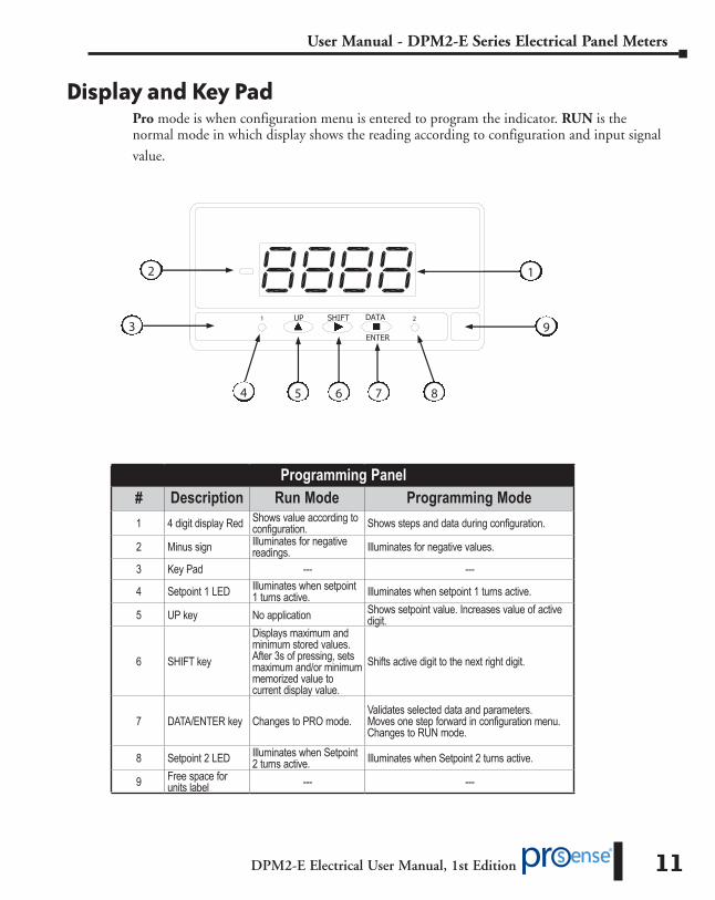
Display and Key PadPro mode is when configuration menu is entered to program the indicator. RUN is the normal mode in which display shows the reading according to configuration and input signal
value.
1 2
1 2
4 5 6 7 8
9 UP SHIFT DATA
ENTER 3
Programming Panel# Description Run Mode Programming Mode1 4 digit display Red Shows value according to
configuration. Shows steps and data during configuration.
2 Minus sign Illuminates for negative readings. Illuminates for negative values.
3 Key Pad --- ---
4 Setpoint 1 LED Illuminates when setpoint 1 turns active. Illuminates when setpoint 1 turns active.
5 UP key No application Shows setpoint value. Increases value of active digit.
6 SHIFT key
Displays maximum and minimum stored values. After 3s of pressing, sets maximum and/or minimum memorized value to current display value.
Shifts active digit to the next right digit.
7 DATA/ENTER key Changes to PRO mode.Validates selected data and parameters. Moves one step forward in configuration menu. Changes to RUN mode.
8 Setpoint 2 LED Illuminates when Setpoint 2 turns active. Illuminates when Setpoint 2 turns active.
9 Free space for units label --- ---

DPM2-E Electrical User Manual, 1st Edition
User Manual - DPM2-E Series Electrical Panel Meters
12
ConfigurationWhen the power is applied to the meter, a display test begins automatically to check the function of LED’s and digits. Once this test is finished the display shows the internal software version and then the unit goes to RUN mode.
Configuration follows a structure composed of a number of menus and submenus. By pressing ENTER key, display shows “Pro”, pressing again allows access to the main menu level which includes the menus for input configuration (InP), display configuration (dSP) and relay setpoints configuration (SEtP) if relays are present in the meter.
If configuration has been totally locked-out, when pressing ENTER key to get into main menu, display shows “dAtA” instead of “Pro”. This indicates that it is only possible to see programmed information and that it is not allowed to modify any parameter from the entire configuration. In this visualization mode, the meter automatically switches back to RUN mode after 15 seconds since last key press.
MAIN MENU
ENTER: Vertical displacement / Validates data.
UP: Increases active digit value.
SHIFT: Horizontal displacement / Changes active digit.
Once inside each menu, all configuration parameters are sequentially shown and they can then be introduced or edited by pressing ENTER key. Numeric values must be entered digit by digit, first selecting digit and then changing its value. When the desired display value is reached, press the ENTER key to validate the data and move forward to next configuration step.
Data entered or changed during configuration are stored in device memory only when configuration routine belonging to the respective submenu is completed, not before. On last routine step and after having pressed ENTER key, display indicates “StorE” and the unit goes back again to RUN mode.
Input Configuration
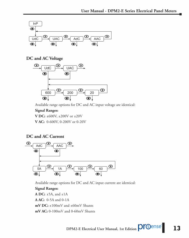
The first menu corresponds to input configuration. This, in turn, consists of four submenus, one for each input type: DC voltage (UDC), AC voltage (UAC), DC current (AdC) and AC current (AAC).
DPM2-E Electrical User Manual, 1st Edition
User Manual - DPM2-E Series Electrical Panel Meters
13
InP
UdC UAC AdC AAC
DC and AC Voltage
UdC
600 200
UAC
20
Available range options for DC and AC input voltage are identical:
Signal Ranges:
V DC: ±600V, ±200V or ±20V
V AC: 0-600V, 0-200V or 0-20V
DC and AC Current
AdC
5A 1A
AAC
60100
Available range options for DC and AC input current are identical:
Signal Ranges:
A DC: ±5A, and ±1A
A AC: 0-5A and 0-1A
mV DC: ±100mV and ±60mV Shunts
mV AC: 0-100mV and 0-60mV Shunts

DPM2-E Electrical User Manual, 1st Edition
User Manual - DPM2-E Series Electrical Panel Meters
14
Display ConfigurationThe second menu corresponds to display configuration consisting of submenus according to previously programmed input type.
FACTORY CALIBRATED RANGE “CAL”
Use the factory calibrated input range and display values based on the Input Signal Type selected.
THROUGH FRONTAL KEYS CONFIGURATION “SCAL”
Input and display values are configured manually through the three keys of the instrument. This method is suitable when signal values at each extreme point of the process are known.
REAL INPUT SIGNAL CONFIGURATION “tEAC”
Input values are entered by introducing actual electrical parameter values. The input signal must be connected to the meter at the CN2 input connector and operational. Display values are configured manually through the three keys, as in the previous case. This method is suitable when signal values at each point are unknown but, it is possible to drive the process to the conditions defined by these extreme points.
WEIGHTED AVERAGE FILTER “FiLt”
Sets low-pass filter cutoff frequency (Fc) which allows the meter to smooth out undesirable display reading fluctuations.
Display Scaling
Display scaling is necessary when adapting display reading to a particular engineering unit. Display range can be configured between -9999 and 9999.
Display scaling is a linear process that consists in introducing two input values, referred as Input 1 and Input 2, and their respective display values, referred as Display 1 and Display 2. On the basis of this proportional relationship internal software calculates display value that would correspond
SCAL tEAC FiLt
uSEr CAL
dSP

DPM2-E Electrical User Manual, 1st Edition
User Manual - DPM2-E Series Electrical Panel Meters
15
to a given input value. Decimal point position is selectable and completes the engineering units indication configuration.
It is possible to scale display in an direct acting (increasing) or reverse acting (decreasing) proportional mode depending on whether the second display value (DISP.2) is greater or less than the first (DISP.1). In an increasing mode, display value increases proportionally to the input value whereas in a decreasing mode, display value decreases.
Direct acting (increasing) proportional mode
Reverse acting (decreasing) proportional mode
DISPLAY 2
DISPLAY 1
DISPLAY 1
DISPLAY 2
INPUT 1 INPUT 2 INPUT 1 INPUT 2
IMPORTANT IN “tEAC” MODE:
To ensure the best accuracy, both points 1 and 2 should represent extreme electrical parameter limits.
The figure below shows an example for a 5 Amp current transformer. Decimal point is situated between second and third digit of the display.
(5.00) DISP.2
(00.00)
DISP.1
(0.00) INP.1
(5.00) INP.2

DPM2-E Electrical User Manual, 1st Edition
User Manual - DPM2-E Series Electrical Panel Meters
16
In “SCAL” method, all values must be manually introduced through the three frontal keys whereas in “tEAC” method, input signal value must be present at the conector at each point that is intended to be configured.
FIRST POINT INPUT AND DISPLAY VALUE:
InP1: Input value indication. 000: Value entered in counts within available model display range. dSP1: Display value indication. 0000: Value entered in counts within display range.
DECIMAL POINT:
00.00: Setting of decimal point position. (Decimal point can be located in any position, and will be the same for Display 1 and Display 2. This position remains fixed for all configuration steps and also for RUN mode).
SECOND POINT INPUT AND DISPLAY VALUE:
InP2: Input value indication. 0000: Value entered in counts within display range. dSP2: Display value indication. 0000: Value entered in counts within display range.
WEIGHTED AVERAGE FILTER:
FiLt: 0 to 9 selectable for low pass filter cut-off frequency.
Value Fc (Hz) Value Fc (Hz)
0 -- 5 2.2
1 7.3 6 1.6
2 5.1 7 1.1
3 3.8 8 0.5
4 2.9 9 0.2
.

DPM2-E Electrical User Manual, 1st Edition
User Manual - DPM2-E Series Electrical Panel Meters
17
Relay Setpoint ConfigurationThe third menu “SEtP” only appears for the DPM2 with relay outputs.
RELAY OUTPUT OPTION
Programming steps are equal for both relays on each “SEt1” and “SEt2” submenus. The parameters to be configured are the following:
SETPOINT VALUE:
00.00: Value entered in counts within display range. (The decimal point position is previously defined in display configuration menu).
ACTIVATING MODE:
Hi: High level relay activation.
Lo: Low level relay activation.
In HI mode, relay output activates when display value goes above setpoint level, whereas in LO mode, relay output activates when display value falls below setpoint level.
RESTING CONTACTS STATE:
NO: Normally open contact.
NC: Normally closed contact.
.
DPM2-E Electrical User Manual, 1st Edition
User Manual - DPM2-E Series Electrical Panel Meters
18
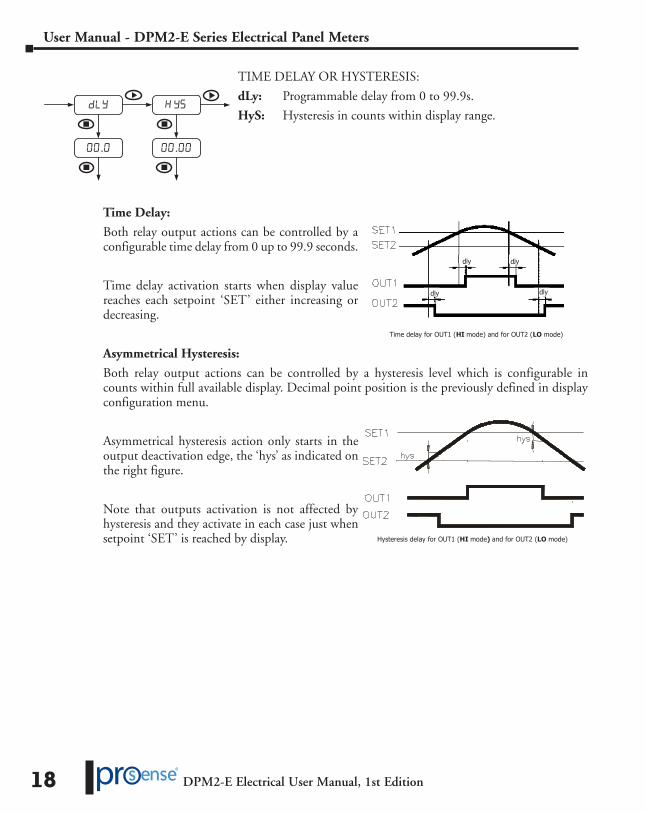
TIME DELAY OR HYSTERESIS:
dLy: Programmable delay from 0 to 99.9s.
HyS: Hysteresis in counts within display range.
Time Delay:
Both relay output actions can be controlled by a configurable time delay from 0 up to 99.9 seconds.
Time delay activation starts when display value reaches each setpoint ‘SET’ either increasing or decreasing.
Asymmetrical Hysteresis:
Both relay output actions can be controlled by a hysteresis level which is configurable in counts within full available display. Decimal point position is the previously defined in display configuration menu.
Asymmetrical hysteresis action only starts in the output deactivation edge, the ‘hys’ as indicated on the right figure.
Note that outputs activation is not affected by hysteresis and they activate in each case just when setpoint ‘SET’ is reached by display.
. .
Time delay for OUT1 (HI mode) and for OUT2 (LO mode)
dly dly
dlydly
Hysteresis delay for OUT1 (HI mode) and for OUT2 (LO mode)
DPM2-E Electrical User Manual, 1st Edition
User Manual - DPM2-E Series Electrical Panel Meters
19
Additional Functions
MAX/MIN and RESET Functions
This device detects and stores in memory maximum and minimum values reached by the input signal. This values are kept in memory although power supply is disconnected. When repeatedly pressing SHIFT key, MAX/MIN function shows saved maximum and minimum values in display since last RESET function activation.
In order to differentiate this value’s indication from RUN mode indication, decimal point blinks while these values are shown. The unit automatically switches back to RUN mode after 15 seconds have elapsed since the last key press.
First SHIFT key pressing shows “MAH” in display followed by the maximum value, a second pressing now shows “Min” followed by the minimum value and finally, a third pressing shows “run” before returning to RUN mode.
RESET function is activated while visualizing maximum or minimum values and the SHIFT key is pressed for at least 3 seconds. If maximum is the displayed value, current input signal value will replace the previous maximum saved value. In the same way, current input signal will replace saved minimum value while the minimum value is displayed.
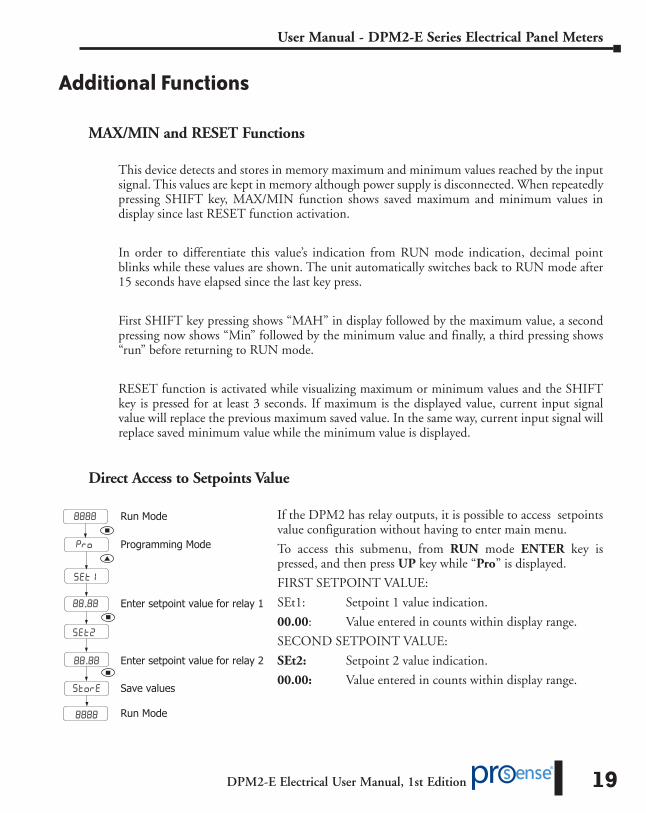
Direct Access to Setpoints Value
If the DPM2 has relay outputs, it is possible to access setpoints value configuration without having to enter main menu.
To access this submenu, from RUN mode ENTER key is pressed, and then press UP key while “Pro” is displayed.
FIRST SETPOINT VALUE:
SEt1: Setpoint 1 value indication.
00.00: Value entered in counts within display range.
SECOND SETPOINT VALUE:
SEt2: Setpoint 2 value indication.
00.00: Value entered in counts within display range.
Enter setpoint value for relay 1
Enter setpoint value for relay 2
Run Mode
Run Mode
Programming Mode
Save values
.
.

DPM2-E Electrical User Manual, 1st Edition
User Manual - DPM2-E Series Electrical Panel Meters
20
Return to Factory Configuration
To access this menu from RUN mode, press ENTER key and while display shows “Pro” press again ENTER for at least 3 seconds.
Display shows now “00” and ‘74’ code must be introduced through SHIFT and UP keys.
Finally press ENTER to validate configuration and back to RUN mode.
Configuration Lock-Out
In order to prevent accidental or undesirable modifications of instrument parameters, a selective or total configuration lock-out is available. By default the unit is delivered unlocked, giving access to all programming levels. Once in this menu, the first option will be to choose between lock-out level setting (“LiSt”) or security access code changing (“CHAn”).
To access this menu from RUN mode, press ENTER key for at least 3 seconds.
Display now shows “CodE” and then “0000”. Desired security code must be introduced through SHIFT and UP keys (by default this code is 0000).
Finally press ENTER to begin with lock-out level configuration. If entered security code is wrong, the instrument will go back to RUN mode.
3sec
>3sec
Run mode
Programming modeIf parameter lock out has been enabled,dAtA will be displayed instead of Pro.
Enter code 74
Save values
Run mode

DPM2-E Electrical User Manual, 1st Edition
User Manual - DPM2-E Series Electrical Panel Meters
21
Configuration Lock-Out Continued
If “LiSt” option is selected, display will show momentarily “tLoc”. Total configuration lock-out is activated by selecting “YES”, then routine directly jumps to MAX/MIN lock-out configuration before the unit goes back to RUN mode. When total lock-out is set, no data can be entered or modified, although it will still be possible to visualize all programmed parameters. Under these conditions when entering main menu, initial indication will be “dAtA” instead of “Pro”.
On the other hand, when “no” option is selected, routine moves on to next step to configure a selective lock-out. When a selective lock-out is set, only non-locked data can be entered or modified. Under these conditions when entering main menu, initial indication will be “Pro”.
The following configuration access can be locked-out:
• Setpoint 1 configuration (SEt1)
• Setpoint 2 configuration (SEt2)
• Input configuration (InP)
• Display configuration (dSP)
SHIFT key configuration for MAX/MIN function (MAH)
In each case lock-out is activated by selecting “YES” option and deactivated by selecting “no”.Setpoints 1 and 2 configuration lock-out is available only if the DPM2 has output relays.
DPM2-E Electrical User Manual, 1st Edition
User Manual - DPM2-E Series Electrical Panel Meters
22
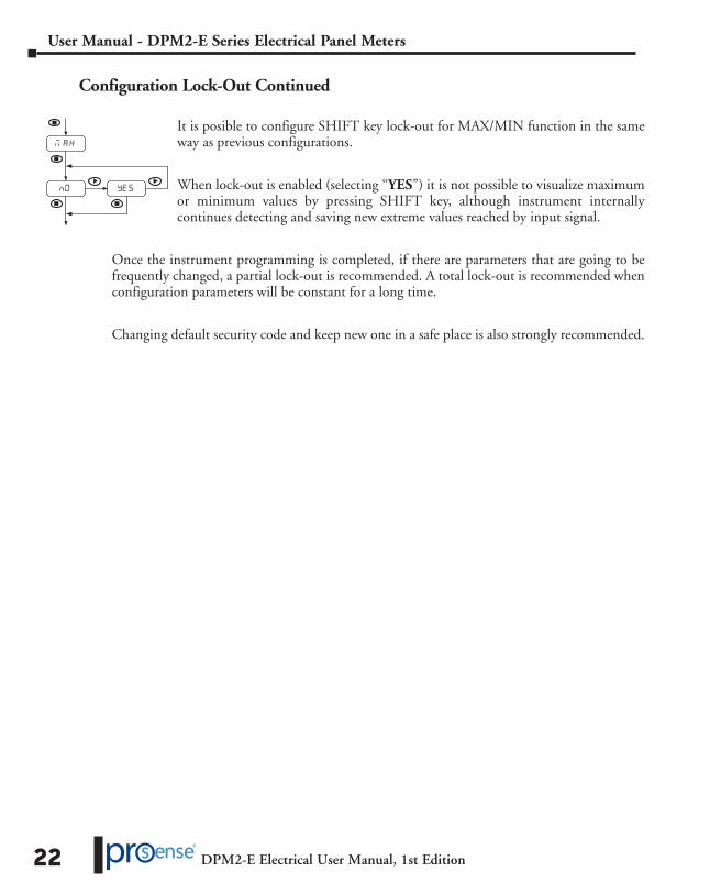
Configuration Lock-Out Continued
It is posible to configure SHIFT key lock-out for MAX/MIN function in the same way as previous configurations.
When lock-out is enabled (selecting “YES”) it is not possible to visualize maximum or minimum values by pressing SHIFT key, although instrument internally continues detecting and saving new extreme values reached by input signal.
Once the instrument programming is completed, if there are parameters that are going to be frequently changed, a partial lock-out is recommended. A total lock-out is recommended when configuration parameters will be constant for a long time.
Changing default security code and keep new one in a safe place is also strongly recommended.
DPM2-E Electrical User Manual, 1st Edition
User Manual - DPM2-E Series Electrical Panel Meters
23
Technical Specifications
Technical Specifications
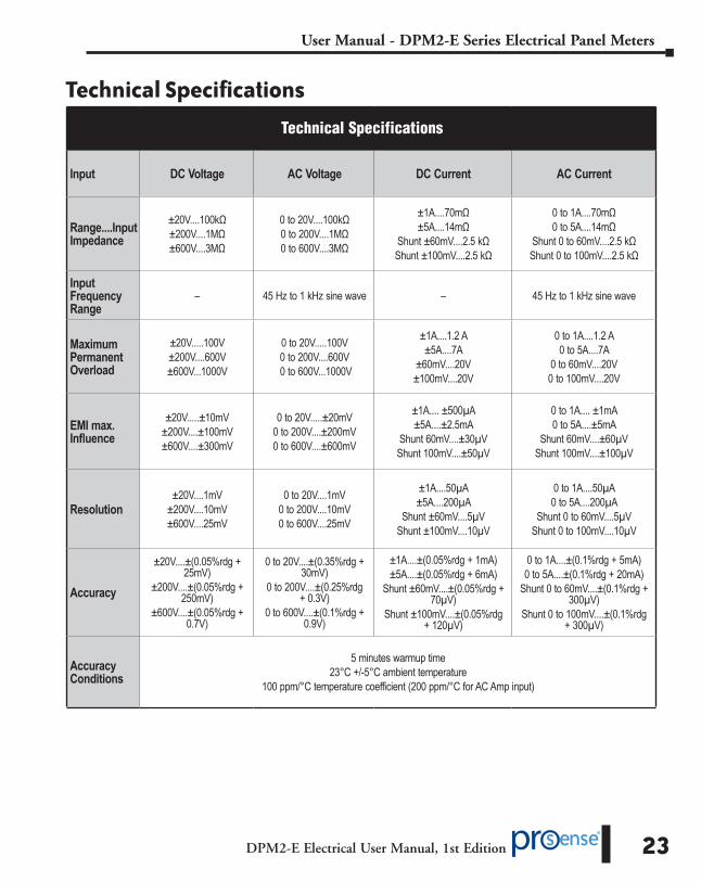
Input DC Voltage AC Voltage DC Current AC Current
Range....Input Impedance
±20V....100kΩ±200V....1MΩ±600V....3MΩ
0 to 20V....100kΩ0 to 200V....1MΩ0 to 600V....3MΩ
±1A....70mΩ±5A....14mΩ
Shunt ±60mV....2.5 kΩShunt ±100mV....2.5 kΩ
0 to 1A....70mΩ0 to 5A....14mΩ
Shunt 0 to 60mV....2.5 kΩShunt 0 to 100mV....2.5 kΩ
Input Frequency Range
– 45 Hz to 1 kHz sine wave – 45 Hz to 1 kHz sine wave
Maximum Permanent Overload
±20V.....100V±200V....600V±600V...1000V
0 to 20V.....100V0 to 200V....600V
0 to 600V...1000V
±1A....1.2 A±5A....7A
±60mV....20V±100mV....20V
0 to 1A....1.2 A0 to 5A....7A
0 to 60mV....20V0 to 100mV....20V
EMI max. Influence
±20V.....±10mV±200V....±100mV±600V....±300mV
0 to 20V.....±20mV0 to 200V....±200mV0 to 600V....±600mV
±1A.... ±500µA±5A....±2.5mA
Shunt 60mV....±30µVShunt 100mV....±50µV
0 to 1A.... ±1mA0 to 5A....±5mA
Shunt 60mV....±60µVShunt 100mV....±100µV
Resolution±20V....1mV
±200V....10mV±600V....25mV
0 to 20V....1mV0 to 200V....10mV0 to 600V....25mV
±1A....50µA±5A....200µA
Shunt ±60mV....5µVShunt ±100mV....10µV
0 to 1A....50µA0 to 5A....200µA
Shunt 0 to 60mV....5µVShunt 0 to 100mV....10µV
Accuracy
±20V....±(0.05%rdg + 25mV)
±200V....±(0.05%rdg + 250mV)
±600V....±(0.05%rdg + 0.7V)
0 to 20V....±(0.35%rdg + 30mV)
0 to 200V....±(0.25%rdg + 0.3V)
0 to 600V....±(0.1%rdg + 0.9V)
±1A....±(0.05%rdg + 1mA)±5A....±(0.05%rdg + 6mA)
Shunt ±60mV....±(0.05%rdg + 70µV)
Shunt ±100mV....±(0.05%rdg + 120µV)
0 to 1A....±(0.1%rdg + 5mA)0 to 5A....±(0.1%rdg + 20mA)
Shunt 0 to 60mV....±(0.1%rdg + 300µV)
Shunt 0 to 100mV....±(0.1%rdg + 300µV)
Accuracy Conditions
5 minutes warmup time23°C +/-5°C ambient temperature
100 ppm/°C temperature coefficient (200 ppm/°C for AC Amp input)
DPM2-E Electrical User Manual, 1st Edition
User Manual - DPM2-E Series Electrical Panel Meters
24
Technical Specifications Continued
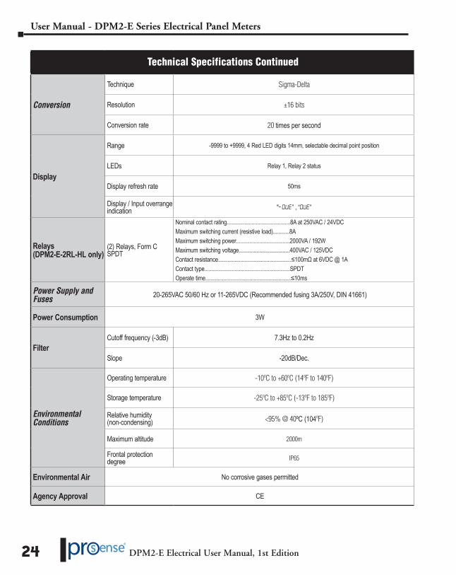
Conversion
Technique Sigma-Delta
Resolution ±16 bits
Conversion rate 20 times per second
Display
Range -9999 to +9999, 4 Red LED digits 14mm, selectable decimal point position
LEDs Relay 1, Relay 2 status
Display refresh rate 50ms
Display / Input overrange indication "-OuE” , “OuE”
Relays (DPM2-E-2RL-HL only)
(2) Relays, Form C SPDT
Nominal contact rating..............................................8A at 250VAC / 24VDCMaximum switching current (resistive load)............8AMaximum switching power.......................................2000VA / 192WMaximum switching voltage.....................................400VAC / 125VDCContact resistance.....................................................≤100mΩ at 6VDC @ 1AContact type..............................................................SPDTOperate time..............................................................≤10ms
Power Supply and Fuses 20-265VAC 50/60 Hz or 11-265VDC (Recommended fusing 3A/250V, DIN 41661)
Power Consumption 3W
FilterCutoff frequency (-3dB) 7.3Hz to 0.2Hz
Slope -20dB/Dec.
Environmental Conditions
Operating temperature -10ºC to +60ºC (14ºF to 140ºF)
Storage temperature -25ºC to +85ºC (-13ºF to 185ºF)
Relative humidity (non-condensing) <95% @ 40ºC (104ºF)
Maximum altitude 2000m
Frontal protection degree IP65
Environmental Air No corrosive gases permitted
Agency Approval CE

DPM2-E Electrical User Manual, 1st Edition
User Manual - DPM2-E Series Electrical Panel Meters
25
Instrumentation Configuration Notes
INPUT:
TYPE:
RANGE:
DISPLAY:
CONFIG. MODE:
INPUT 1:
DISPLAY 1:
INPUT 2:
DISPLAY 2:
FILTER (0 ÷ 9):
SETPOINTS:
SET1:
MODE:
DLY:
HYS:
SET2:
MODE:
DLY:
HYS:
LOCK-OUT:
ACCESS CODE:
no nc
no nc
SCAL TEACH CAL