Chapter 08
63
Chapter 8 MAGNETIC FORCES, MATERIALS, AND DEVICES Do all the good you can, By all the means you can, In all the ways you can, In all the places you can, At all the times you can, To all the people you can, As long as ever you can. —JOHN WESLEY 8.1 INTRODUCTION Having considered the basic laws and techniques commonly used in calculating magnetic field B due to current-carrying elements, we are prepared to study the force a magnetic field exerts on charged particles, current elements, and loops. Such a study is important to problems on electrical devices such as ammeters, voltmeters, galvanometers, cyclotrons, plasmas, motors, and magnetohydrodynamic generators. The precise definition of the mag- netic field, deliberately sidestepped in the previous chapter, will be given here. The con- cepts of magnetic moments and dipole will also be considered. Furthermore, we will consider magnetic fields in material media, as opposed to the magnetic fields in vacuum or free space examined in the previous chapter. The results of the preceding chapter need only some modification to account for the presence of materi- als in a magnetic field. Further discussions will cover inductors, inductances, magnetic energy, and magnetic circuits. 8.2 FORCES DUE TO MAGNETIC FIELDS There are at least three ways in which force due to magnetic fields can be experienced. The force can be (a) due to a moving charged particle in a B field, (b) on a current element in an external B field, or (c) between two current elements. 304
-
Upload
chethan-nt -
Category
Documents
-
view
4.983 -
download
2
description
Transcript of Chapter 08
Chapter 8
MAGNETIC FORCES, MATERIALS,AND DEVICES
Do all the good you can,By all the means you can,In all the ways you can,In all the places you can,At all the times you can,To all the people you can,As long as ever you can.
—JOHN WESLEY
8.1 INTRODUCTION
Having considered the basic laws and techniques commonly used in calculating magneticfield B due to current-carrying elements, we are prepared to study the force a magneticfield exerts on charged particles, current elements, and loops. Such a study is important toproblems on electrical devices such as ammeters, voltmeters, galvanometers, cyclotrons,plasmas, motors, and magnetohydrodynamic generators. The precise definition of the mag-netic field, deliberately sidestepped in the previous chapter, will be given here. The con-cepts of magnetic moments and dipole will also be considered.
Furthermore, we will consider magnetic fields in material media, as opposed to themagnetic fields in vacuum or free space examined in the previous chapter. The results ofthe preceding chapter need only some modification to account for the presence of materi-als in a magnetic field. Further discussions will cover inductors, inductances, magneticenergy, and magnetic circuits.
8.2 FORCES DUE TO MAGNETIC FIELDS
There are at least three ways in which force due to magnetic fields can be experienced. Theforce can be (a) due to a moving charged particle in a B field, (b) on a current element in anexternal B field, or (c) between two current elements.
304
8.2 FORCES DUE TO MAGNETIC FIELDS 305
A. Force on a Charged Particle
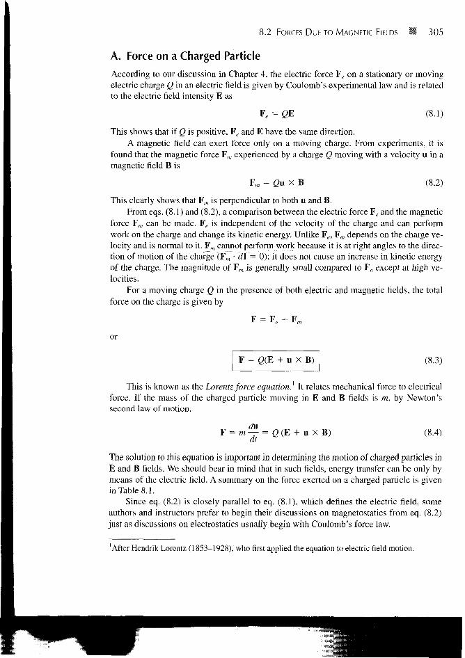
According to our discussion in Chapter 4, the electric force Fe on a stationary or movingelectric charge Q in an electric field is given by Coulomb's experimental law and is relatedto the electric field intensity E as
Fe = QE (8.1)
This shows that if Q is positive, Fe and E have the same direction.A magnetic field can exert force only on a moving charge. From experiments, it is
found that the magnetic force Fm experienced by a charge Q moving with a velocity u in amagnetic field B is
Fm = Qn X B (8.2)
This clearly shows that Fm is perpendicular to both u and B.From eqs. (8.1) and (8.2), a comparison between the electric force ¥e and the magnetic
force Fm can be made. Fe is independent of the velocity of the charge and can performwork on the charge and change its kinetic energy. Unlike Fe, Fm depends on the charge ve-locity and is normal to it. Fm cannot perform work because it is at right angles to the direc-tion of motion of the charge (Fm • d\ = 0); it does not cause an increase in kinetic energyof the charge. The magnitude of Fm is generally small compared to Fe except at high ve-locities.
For a moving charge Q in the presence of both electric and magnetic fields, the totalforce on the charge is given by
F = F + F
or
F = g(E + u X B) (8.3)
This is known as the Lorentz force equation.1 It relates mechanical force to electricalforce. If the mass of the charged particle moving in E and B fields is m, by Newton'ssecond law of motion.
du= m — = (8.4)
The solution to this equation is important in determining the motion of charged particles inE and B fields. We should bear in mind that in such fields, energy transfer can be only bymeans of the electric field. A summary on the force exerted on a charged particle is givenin Table 8.1.
Since eq. (8.2) is closely parallel to eq. (8.1), which defines the electric field, someauthors and instructors prefer to begin their discussions on magnetostatics from eq. (8.2)just as discussions on electrostatics usually begin with Coulomb's force law.
After Hendrik Lorentz (1853-1928), who first applied the equation to electric field motion.

306 W Magnetic Forces, Materials, and Devices
TABLE «.! Force on a Charged Particle
State of Particle E Field B Field Combined E and B Fields
Stationary
Moving Qu X B
QE
2(E + u X B)
B. Force on a Current Element
To determine the force on a current element / dl of a current-carrying conductor due to themagnetic field B, we modify eq. (8.2) using the fact that for convection current [seeeq. (5.7)]:
J = P,u
From eq. (7.5), we recall the relationship between current elements:
Idl = KdS = idv
Combining eqs. (8.5) and (8.6) yields
I dl = pvu dv = dQu
Alternatively, / dl = — dl = dQ — = dQ udt dt
(8.5)
(8.6)
Hence,
Idl = dQu (8.7)
This shows that an elemental charge dQ moving with velocity u (thereby producing con-vection current element dQ u) is equivalent to a conduction current element / dl. Thus theforce on a current element / dl in a magnetic field B is found from eq. (8.2) by merely re-placing Qu by / dl; that is,
d¥ = Idl X B (8.8)
If the current / is through a closed path L or circuit, the force on the circuit is given by
(8.9), F = (b Idl X B i
In using eq. (8.8) or (8.9), we should keep in mind that the magnetic field produced by thecurrent element / dl does not exert force on the element itself just as a point charge doesnot exert force on itself. The B field that exerts force on / dl must be due to anotherelement. In other words, the B field in eq. (8.8) or (8.9) is external to the current element/ dl. If instead of the line current element / dl, we have surface current elements K dS

8.2 FORCES DUE TO MAGNETIC FIELDS 307
or a volume current element J dv, we simply make use of eq. (8.6) so that eq. (8.8)becomes
dF = KdS XB or dF = J dv X B
while eq. (8.9) becomes
F = \ KdSXB or F = J d v X B
(8.8a)
(8.9a)
From eq. (8.8)
The magnetic field B is defined as the force per unit current element.
Alternatively, B may be defined from eq. (8.2) as the vector which satisfies FJq = u X Bjust as we defined electric field E as the force per unit charge, FJq. Both of these defini-tions of B show that B describes the force properties of a magnetic field.
C. Force between Two Current Elements
Let us now consider the force between two elements /[ d\x and I2 d\2- According toBiot-Savart's law, both current elements produce magnetic fields. So we may find theforce d(d¥{) on element /] dl{ due to the field dB2 produced by element I2 d\2 as shown inFigure 8.1. From eq. (8.8),
But from Biot-Savart's law,
Hence,
d(dF}) = 7, d\x X dB2
= /xo/2 d\2 X aRii
^
(8.10)
(8.11)
(8.12)
Figure 8.1 Force between two current loops.

308 Magnetic Forces, Materials, and Devices
This equation is essentially the law of force between two current elements and is analogousto Coulomb's law, which expresses the force between two stationary charges. Fromeq. (8.12), we obtain the total force F, on current loop 1 due to current loop 2 shown inFigure 8.1 as
F, =4TT
X (dl2 X(8.13)
L, JL2
Although this equation appears complicated, we should remember that it is based oneq. (8.10). It is eq. (8.9) or (8.10) that is of fundamental importance.
The force F2 on loop 2 due to the magnetic field Bx from loop 1 is obtained fromeq. (8.13) by interchanging subscripts 1 and 2. It can be shown that F2 = —F^ thus F, andF2 obey Newton's third law that action and reaction are equal and opposite. It is worth-while to mention that eq. (8.13) was experimentally established by Oersted and Ampere;Biot and Savart (Ampere's colleagues) actually based their law on it.
EXAMPLE 8.1A charged particle of mass 2 kg and charge 3 C starts at point (1, - 2 , 0) with velocity4ax + 3az m/s in an electric field 123^ + lOa , V/m. At time t = 1 s, determine
(a) The acceleration of the particle
(b) Its velocity
(c) Its kinetic energy
(d) Its position
Solution:
(a) This is an initial-value problem because initial values are given. According toNewton's second law of motion,
F = ma = QE
where a is the acceleration of the particle. Hence,
QE 3 ,a = — = - (12a., + 10ay) = 18a* + 15aym/s2
du da = — = — (ux, uy, uz) = 18ax + 15a,
(b) Equating components gives
dux
~dt= 18->KX = 18r + A
- ^ = 15 -> «v = 15? + Bdt y
(8.1.1)
(8.1.2)
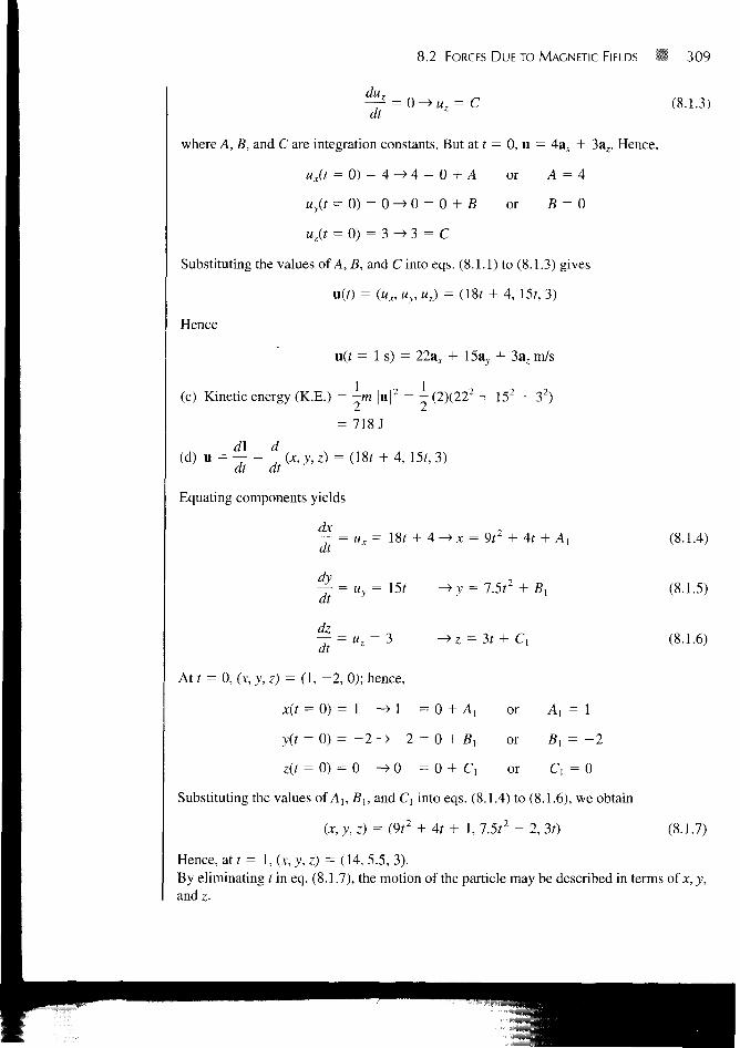
8.2 FORCES DUE TO MAGNETIC FIELDS 309
~dt= 0 - > M 7 = C (8.1.3)
where A, B, and C are integration constants. But at t = 0, u = Aax + 3az. Hence,
ux(t = 0) = 4^>4 = 0 + A or A = 4
uy(t = 0) = 0 - > 0 = 0 + B or B = 0
uz(t = O) = 3 H > 3 = C
Substituting the values of A, B, and C into eqs. (8.1.1) to (8.1.3) gives
u(r) = (wx, MV, Mj) = (18f + 4, 15f, 3)
Hence
u(t = 1 s) = 22a., + 15a}, + 3az m/s
(c) Kinetic energy (K.E.) = -m ju|2 = - (2)(222 + 152 + 32)
= 718J
(d) u = — = —{x,y,z) = (18r + 4, 15?, 3)
Equating components yields
— = ux = 18/ + 4 -^ x = 9r2 + 4f + (8.1.4)
dt ~y ""
— = uz = 3 -> z =
dt
At t = 0, (JC, j , z) = (1, - 2 , 0); hence,
x(t = 0) = 1 -> 1 = 0 + A,
y(f = 0) = - 2 - > - 2 = 0 + B,
z(f = 0) = 0 ^ 0 = 0 + C{ or C, = 0
Substituting the values of Ab Bu and C, into eqs. (8.1.4) to (8.1.6), we obtain
(x, y, z) = (9r2 + 4? + 1, 7.5?2 - 2, 30
or A] = 1
or 5, = - 2
(8.1.5)
(8.1.6)
(8.1.7)
Hence, at t = 1, (*, j , z) = (14, 5.5, 3).By eliminating tm eq. (8.1.7), the motion of the particle may be described in terms of *, y,and z.

310 Magnetic Forces, Materials, and Devices
PRACTICE EXERCISE 8.1
A charged particle of mass 1 kg and charge 2 C starts at the origin with zero initialvelocity in a region where E = 3az V/m. Find
(a) The force on the particle
(b) The time it takes to reach point P(0, 0, 12 m)
(c) Its velocity and acceleration at P
(d) Its K.E. at P.
Answer: (a) 6az N, (b) 2 s, (c) 12az m/s, 6az m/s2, (d) 72 J.
EXAMPLE 8.2A charged particle of mass 2 kg and 1 C starts at the origin with velocity 3av, m/s andtravels in a region of uniform magnetic field B = lOa , Wb/m . At t = 4 s, calculate
(a) The velocity and acceleration of the particle
(b) The magnetic force on it
(c) Its K.E. and location
(d) Find the particle's trajectory by eliminating t.
(e) Show that its K.E. remains constant.
Solution:
du(a) F = m — = Qu X B
dt
du Qa = — = —u X B
dt m
Hence
(uxax + uy&y + uzaz) = - ux uy uz
0 0 10
By equating components, we get
dux
~di
duz
dt
= -5ur
= 5 ( 0 , - Ujiy)
(8.2.1)
(8.2.2)
(8.2.3)

8.2 FORCES DUE TO MAGNETIC FIELDS ** 311
We can eliminate ux or uy in eqs. (8.2.1) and (8.2.2) by taking second derivatives of oneequation and making use of the other. Thus
d2ux duy
dt2 = 5 - = - 2 5 * ,
or
d ux
~d7 25ux = 0
which is a linear differential equation with solution (see Case 3 of Example 6.5)
ux = d cos 5/ + C2 sin 5? (8.2.4)
From eqs. (8.2.1) and (8.2.4),
5M,, = — = - 5 C , sin 5f + 5C2 cos 5t (8.2.5)
dt
or
uy = — d sin 5? + C2 cos 5?We now determine constants Co, Cu and C2 using the initial conditions. At t = 0, u = 3a r
Hence,
ux = 0 -> 0 = Cj • 1 + C2 • 0 -» C, = 0
uy = 3 -^ 3 = - d • 0 + C2 • 1 -» C2 = 3
uz = 0 -» 0 = Co
Substituting the values of Co, C,, and C2 into eqs. (8.2.3) to (8.2.5) gives
u = (ux, uy, uz) = (3 sin 5;, 3 cos 5t, 0) (8.2.6)
Hence,
and
(b)
or
U(f = 4) = (3 sin 20, 3 cos 20, 0)= 2.739ax + 1.224ay m/s
dua = — = (15 cos 5f, - 15 sin 5t, 0)
if
a(f = 4) = 6.101a* - 13.703avm/s2
F = ma = 12.2ax - 27.4avN
F = gu X B = (1X2.7398* + 1.224av) X 10a,= 12.2a*- 27.4a,, N

312 Magnetic Forces, Materials, and Devices
(c) K.E. = l/2m |u|2 = 1/2(2) (2.7392 + 1.2242) = 9 J
ux = — = 3 sin 5f —> x = —— cos 5? + bx
dy 3uy = — = 3 cos 5f -> y = - sin 5t + b2
at 5
dz
dt
(8.2.7)
(8.2.8)
(8.2.9)
where bu b2, and b3 are integration constants. At t = 0, (x, y, z) = (0, 0, 0) and hence,
x(t = 0) = 0 -> 0 = 1 = 0.6
y(t = 0) = 0 0 = - • 0 + b2 -> 62 = 0
(8.2.10)
z(/ = 0) = 0 -> 0 = &3
Substituting the values of bt, b2, and b3 into eqs. (8.2.7) to (8.2.9), we obtain
(x, y, z) = (0.6 - 0.6 cos 5?, 0.6 sin 5f, 0)
At t = 4 s,
(x, y, z) = (0.3552, 0.5478, 0)
(d) From eq. (8.2.10), we eliminate t by noting that
(x - 0.6)2 + y2 = (0.6)2 (cos2 5t + sin2 5?), z = 0
or
(x - 0.6)2 + y2 = (0.6)2, z = 0
which is a circle on plane z = 0, centered at (0.6, 0, 0) and of radius 0.6 m. Thus the parti-cle gyrates in an orbit about a magnetic field line.
(e) K.E. = -m |u|2 = - ( 2 ) (9 cos2 5t + 9 sin2 5t) = 9 J
which is the same as the K.E. at t = 0 and t = 4 s. Thus the uniform magnetic field has noeffect on the K.E. of the particle.
Note that the angular velocity cu = QBIm and the radius of the orbit r = uju>, whereMO is the initial speed. An interesting application of the idea in this example is found in acommon method of focusing a beam of electrons. The method employs a uniform mag-netic field directed parallel to the desired beam as shown in Figure 8.2. Each electronemerging from the electron gun follows a helical path and is back on the axis at the samefocal point with other electrons. If the screen of a cathode ray tube were at this point, asingle spot would appear on the screen.

8.2 FORCES D U E TO MAGNETIC FIELDS W 313
focal pointFigure 8.2 Magnetic focusing of abeam of electrons: (a) helical pathsof electrons, (b) end view of paths.
(a) (b)
PRACTICE EXERCISE 8.2
A proton of mass m is projected into a uniform field B = Boaz with an initial veloc-ity aax + /3ar (a) Find the differential equations that the position vector r =xax + yay + zaz must satisfy, (b) Show that a solution to these equations is
ax = — sin oit,
0)
ay — — cos ut,
where w = eBJm and e is the charge on the proton, (c) Show that this solution de-scribes a circular helix in space.
Answer: (a) — = a cos ut,— — -a sin cat, — = j3, (b) and (c) Proof.at at at
EXAMPLE 8.3A charged particle moves with a uniform velocity 4ax m/s in a region whereE = 20 ay V/m and B = Boaz Wb/m2. Determine Bo such that the velocity of the particleremains constant.
Solution:
If the particle moves with a constant velocity, it implies that its acceleration is zero. Inother words, the particle experiences no net force. Hence,
0 = 2 (20av + 4ax X Boa,)
or
-20av = -ABoay
Thus Bo = 5.This example illustrates an important principle employed in a velocity filter shown in
Figure 8.3. In this application, E, B, and u are mutually perpendicular so that Qu X B is

314 Magnetic Forces, Materials, and Devices
charged _ uparticles
Aperture^_ Particles with
constant velocity
F m = Q u X B
Figure 8.3 A velocity filter for charged particles.
directed opposite to QE, regardless of the sign of the charge. When the magnitudes of thetwo vectors are equal,
QuB = QE
or
This is the required (critical) speed to balance out the two parts of the Lorentz force. Parti-cles with this speed are undeflected by the fields; they are "filtered" through the aperture.Particles with other speeds are deflected down or up, depending on whether their speedsare greater or less than this critical speed.
PRACTICE EXERCISE 8.3
Uniform E and B fields are oriented at right angles to each other. An electron moveswith a speed of 8 X 10⁶ m/s at right angles to both fields and passes undeflectedthrough the field.
(a) If the magnitude of B is 0.5 mWb/m2, find the value of E.
(b) Will this filter work for positive and negative charges and any value of mass?
Answer: (a) 4 kV/m, (b) Yes.
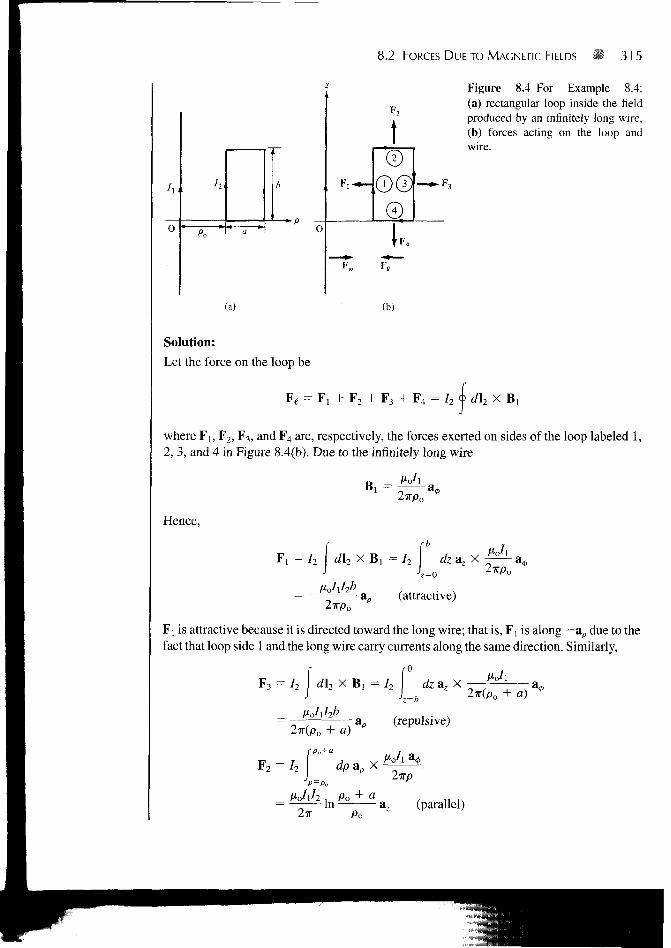
EXAMPLE 8.4A rectangular loop carrying current I2 is placed parallel to an infinitely long filamentarywire carrying current Ix as shown in Figure 8.4(a). Show that the force experienced by theloop is given by
2x1_
iPo
1
po
8.2 FORCES DUE TO MAGNETIC FIELDS 315
(a)
-2-H
w
Figure 8.4 For Example 8.4:(a) rectangular loop inside the fieldproduced by an infinitely long wire,(b) forces acting on the loop andwire.
(b)
Solution:
Let the force on the loop be
F 4 = I? <\> dh X B ,¥( = F, + F7 +
where F b F2 , F3 , and F 4 are, respectively, the forces exerted on sides of the loop labeled 1,2, 3, and 4 in Figure 8.4(b). Due to the infinitely long wire
a2TTPO
Hence,
F, = I2 | d\2 X Bl = I2 dz az X
2irpoao (attractive)
Fj is attractive because it is directed toward the long wire; that is, F, is along -ap due to thefact that loop side 1 and the long wire carry currents along the same direction. Similarly,
F 3 = I2 d\2 X B, = I2 i7 X
z=b2TT(PO + a)
2TT(PO + a)
F 2 = 72 I i p ap X
A'c/l^ , Po + Cl
= — In ;2TT P O
(repulsive)
(parallel)
316 Magnetic Forces, Materials, and Devices
dpap x
V-Jih , Po + a2TT
In az (parallel)
The total force Fe on the loop is the sum of F l5 F2, F3, and F4; that is,
1 1F, =
2w po + a_
which is an attractive force trying to draw the loop toward the wire. The force Fw on thewire, by Newton's third law, is — F^; see Figure 8.4(b).
PRACTICE EXERCISE 8.4
In Example 8.4, find the force experienced by the infinitely long wire if lx = 10 A,I2 — 5 A, po = 20 cm, a = 10 cm, b — 30 cm.
Answer: Sa £tN.
8.3 MAGNETIC TORQUE AND MOMENT
Now that we have considered the force on a current loop in a magnetic field, we can deter-mine the torque on it. The concept of a current loop experiencing a torque in a magneticfield is of paramount importance in understanding the behavior of orbiting charged parti-cles, d.c. motors, and generators. If the loop is placed parallel to a magnetic field, it expe-riences a force that tends to rotate it.
The torque T (or mechanical moincnl of force) on ihe loop is the \cclor product ofthe force F and iho momem arm r.
That is,
T = r X F (8.14)
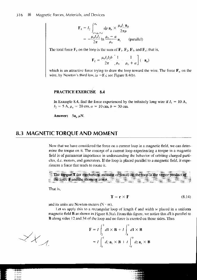
and its units are Newton-meters (N • m).Let us apply this to a rectangular loop of length € and width w placed in a uniform
magnetic field B as shown in Figure 8.5(a). From this figure, we notice that d\ is parallel toB along sides 12 and 34 of the loop and no force is exerted on those sides. Thus
F = / d \ X B + I \ d \ X B
{ 0
= / dz az X B + / dz a z X B'0 'e
8.3 MAGNETIC TORQUE AND MOMENT •< 317
it//2~—w-f-
1
3 . / 4f l / /
1 / B
I fl
i I
— axis of rotation
(a) (b)
Figure 8.5 Rectangular planar loop in a uniform magnetic field.
or
F = Fo - Fo = 0 (8.15)
where |F0| = IB£ because B is uniform. Thus, no force is exerted on the loop as a whole.However, Fo and — Fo act at different points on the loop, thereby creating a couple. If thenormal to the plane of the loop makes an angle a with B, as shown in the cross-sectionalview of Figure 8.5(b), the torque on the loop is
|T| = |FO| ws ina
or
T = Bliw sin a
But €w = S, the area of the loop. Hence,
T = BIS sin a
We define the quantity
! m = ISa,
(8.16)
(8.17)
(8.18)
as the magnetic dipole moment (in A/m2) of the loop. In eq. (8.18), an is a unit normalvector to the plane of the loop and its direction is determined by the right-hand rule: fingersin the direction of current and thumb along an.
The magnetic dipolc moment is the product of current and area of the loop; its di-rection is normal to the loop.
Introducing eq. (8.18) in eq. (8.17), we obtain
| T = m X B (8.19)

318 Magnetic Forces, Materials, and Devices
This expression is generally applicable in determining the torque on a planar loop of anyarbitrary shape although it was obtained using a rectangular loop. The only limitation isthat the magnetic field must be uniform. It should be noted that the torque is in the direc-tion of the axis of rotation (the z-axis in the case of Figure 8.5a). It is directed such as toreduce a so that m and B are in the same direction. In an equilibrium position (when m andB are in the same direction), the loop is perpendicular to the magnetic field and the torquewill be zero as well as the sum of the forces on the loop.
8.4 A MAGNETIC DIPOLE
A bar magnet or a small filamentary current loop is usually referred to as a magneticdipole. The reason for this and what we mean by "small" will soon be evident. Let us de-termine the magnetic field B at an observation point P(r, 8, 4>) due to a circular loop carry-ing current / as in Figure 8.6. The magnetic vector potential at P is
(8.20)
It can be shown that at far field (r ^> a, so that the loop appears small at the observationpoint), A has only 0-component and it is given by
(8.21a)
or
A
jxj-wa sin
4TIT2
^ o m X
47rr2
ar(8.21b)
P(r, 6, 0)
Figure 8.6 Magnetic field at P due to a currentloop.

8.4 A MAGNETIC DIPOLE 319
where m = Iira2az, the magnetic moment of the loop, and a, X ar = sin d a0. We deter-mine the magnetic flux density B from B = V X A as
B = ~ : (2 cos 6 ar + sin 6 ; (8.22)
It is interesting to compare eqs. (8.21) and (8.22) with similar expressions ineqs. (4.80) and (4.82) for electrical potential V and electric field intensity E due to an elec-tric dipole. This comparison is done in Table 8.2, in which we notice the striking similari-
TABLE 8.2 Comparison between Electric and Magnetic Monopoles and Dipoles
Electric
V -
Monopoie (point charge)
Qcasd
EQd
(2 cos B ar + sin1©:
+0
Dipole (two point charge)
Magnetic
Does not exist
Qm
Monopoie (point charge)
A = •
sin 0 i 0
4irr2
Me,B = (2 cos Hr + sin 9ae)
47TC3
Dipole (small current loop or bar magnet)
320 Magnetic Forces, Materials, and Devices
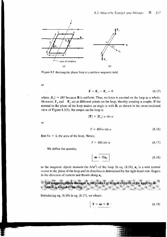
Figure 8.7 The B lines due tomagnetic dipoles: (a) a smallcurrent loop with m = IS, (b) abar magnet with m = Qm€.
(a) (b)
ties between B as far field due to a small current loop and E at far field due to an electricdipole. It is therefore reasonable to regard a small current loop as a magnetic dipole. The Blines due to a magnetic dipole are similar to the E lines due to an electric dipole. Figure8.7(a) illustrates the B lines around the magnetic dipole m = IS.
A short permanent magnetic bar, shown in Figure 8.7(b), may also be regarded as amagnetic dipole. Observe that the B lines due to the bar are similar to those due to a smallcurrent loop in Figure 8.7(a).
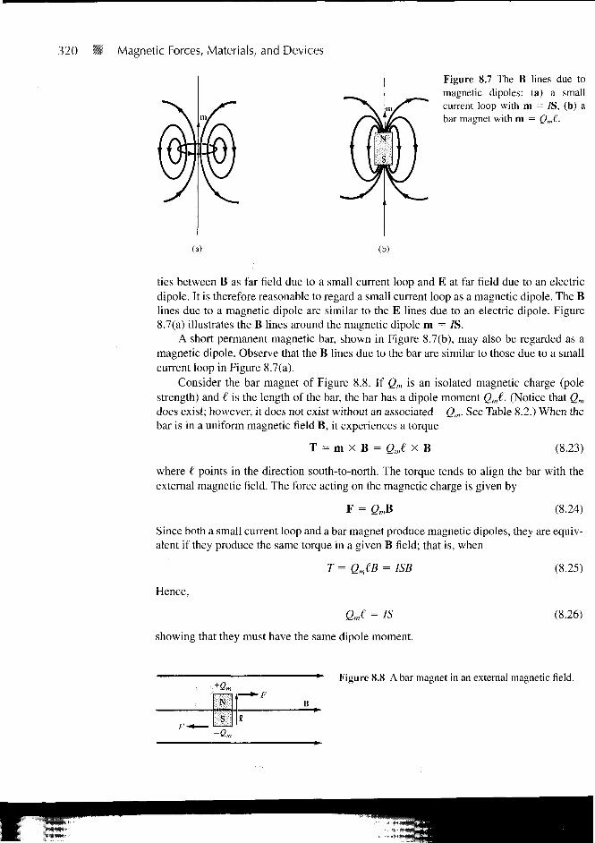
Consider the bar magnet of Figure 8.8. If Qm is an isolated magnetic charge (polestrength) and € is the length of the bar, the bar has a dipole moment Qm€. (Notice that Qm
does exist; however, it does not exist without an associated — Qm. See Table 8.2.) When thebar is in a uniform magnetic field B, it experiences a torque
T=mXB=2JXB (8.23)
where € points in the direction south-to-north. The torque tends to align the bar with theexternal magnetic field. The force acting on the magnetic charge is given by
F = QmB (8.24)
Since both a small current loop and a bar magnet produce magnetic dipoles, they are equiv-alent if they produce the same torque in a given B field; that is, when
T = QJB = ISB
Hence,
QJ = IS
showing that they must have the same dipole moment.
(8.25)
(8.26)
nsrl«
*~FB
Figure 8.8 A bar magnet in an external magnetic field.
8.4 A MAGNETIC DIPOLE 321
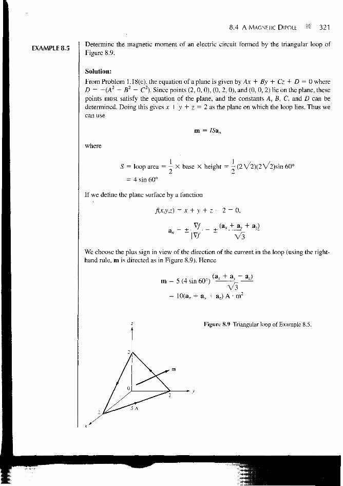
EXAMPLE 8.5Determine the magnetic moment of an electric circuit formed by the triangular loop ofFigure 8.9.
Solution:
From Problem 1.18(c), the equation of a plane is given by Ax + By + Cz + D = 0 whereD= -(A2 + B2 + C2). Since points (2, 0, 0), (0, 2, 0), and (0, 0, 2) lie on the plane, thesepoints must satisfy the equation of the plane, and the constants A, B, C, and D can bedetermined. Doing this gives x + y + z = 2 as the plane on which the loop lies. Thus wecan use
m = ISan
where
S = loop area = - X base X height = - (2 V2)(2 V2)sin 60°
= 4 sin 60°
If we define the plane surface by a function
f(x,y,z) = x + y + z ~ 2 = 0,
V / ^ (a = ±
ay + az)
V 3
We choose the plus sign in view of the direction of the current in the loop (using the right-hand rule, m is directed as in Figure 8.9). Hence
^ (a, + ay + a,)m = 5 (4 sin 60°) r-
V 3= 10(ax + ay + a,) A • m2
Figure 8.9 Triangular loop of Example 8.5.

322 B Magnetic Forces, Materials, and Devices
PRACTICE EXERCISE 8.5
A rectangular coil of area 10 cm2 carrying current of 50 A lies on plane2x + 6y - 3z = 7 such that the magnetic moment of the coil is directed away fromthe origin. Calculate its magnetic moment.
Answer: (1.429a, + 4.286a,, - 2.143az) X 10~2 A • m2
EXAMPLE 8.6A small current loop L, with magnetic moment 53;, A/m is located at the origin whileanother small loop current L2 with magnetic moment 3ay A • m2 is located at (4, —3, 10).Determine the torque on L2.
Solution:
The torque T2 on the loop L2 is due to the field Bj produced by loop L,. Hence,
T2 = m2 X B,
Since m, for loop Lx is along az, we find Bj using eq. (8.22):
B =4irr
(2 cos 9 ar + sin 8 ag)
Using eq. (2.23), we transform m2 from Cartesian to spherical coordinates:
m2 = 3av = 3 (sin 6 sin 4> ar + cos 6 sin 0 ae + cos <t> a^)
At (4, - 3 , 10),
r = V 4 2 + (-3)2 + 102 = 5 V 5
2
V5
Hence,
p 5 1 1tan 6 = — = — = >sin0 = —1=,
z 10 2 V ?COS P =
y - 3 - 3 4t a n <j) = — = > sin 0 = , c o s <j> = —
B_ 4 x X 1 0 ' 7 X 5 / 4 1— j= I j= ar H -j= ae
47T625V5 VV5 V510"7
(4ar + a,)625
m2 - 35V5 5V5 5
8.5 MAGNETIZATION IN MATERIALS 323
and
T =1 0
4V/5a<A) X (4ar1_ ( 3 a r 6625 (5 V5)
= 4.293 X 10"" (-6a r + 38.78ae + 24a0)= -0.258ar + 1.665a,, + l.O3a0nN • m
PRACTICE EXERCISE 8.6
If the coil of Practice Exercise 8.5 is surrounded by a uniform field 0.6ax + 0.43^ +0.5a. Wb/m2,
(a) Find the torque on the coil.
(b) Show that the torque on the coil is maximum if placed on plane 2x - 8>' +4z = V84. Calculate the value of the maximum torque.
Answer: (a) 0.03a,, - 0.02av - 0.02a. N • m, (b) 0.04387 N • m.
8.5 MAGNETIZATION IN MATERIALS
Our discussion here will parallel that on polarization of materials in an electric field. Weshall assume that our atomic model is that of an electron orbiting about a positive nucleus.
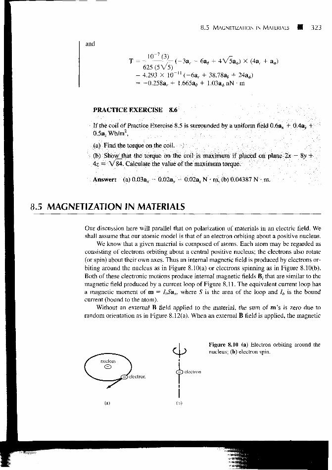
We know that a given material is composed of atoms. Each atom may be regarded asconsisting of electrons orbiting about a central positive nucleus; the electrons also rotate(or spin) about their own axes. Thus an internal magnetic field is produced by electrons or-biting around the nucleus as in Figure 8.10(a) or electrons spinning as in Figure 8.10(b).Both of these electronic motions produce internal magnetic fields B, that are similar to themagnetic field produced by a current loop of Figure 8.11. The equivalent current loop hasa magnetic moment of m = IbSan, where S is the area of the loop and Ib is the boundcurrent (bound to the atom).
Without an external B field applied to the material, the sum of m's is zero due torandom orientation as in Figure 8.12(a). When an external B field is applied, the magnetic
Figure 8.10 (a) Electron orbiting around thenucleus; (b) electron spin.
nucleus
23 electron(J) electron
(a)

324 Magnetic Forces, Materials, and Devices
Figure 8.11 Circular current loop equivalent to electronic motion ofFigure 8.10.
moments of the electrons more or less align themselves with B so that the net magneticmoment is not zero, as illustrated in Figure 8.12(b).
The magnetization M (in amperes/meter) is the magnetic dipole moment per unitvolume.
If there are N atoms in a given volume Av and the kth atom has a magnetic moment m*.,
M = lim k-\
>0 Av(8.27)
A medium for which M is not zero everywhere is said to be magnetized. For a differentialvolume dv', the magnetic moment is dm = M dv'. From eq. (8.21b), the vector magneticpotential due to dm is
dX =X
A-KR1dv' =
According to eq. (7.46),
R
X R-dv'
B = 0, M = 0Hgurc 8.! 2 Magnetic dipole mo-ment in a volume Av: (a) before B isapplied, (b) after B is applied.
(a) (b)

8.5 MAGNETIZATION IN MATERIALS 325
Hence,
Using eq. (7.48) gives
A = — I M X V - dv'4TT R
(8.28)
' - = -V'XM-V'X-
Substituting this into eq. (8.28) yields
4TT Jy, R 4TT JV, fl
Applying the vector identity
V X F dv' = - <J> F X r f S
to the second integral, we obtain
4TT JV, J? 4TT JS , R
Ho f ibdv' JXO(8.29)
4ir )v, R 4TT )S. R
Comparing eq. (8.29) with eqs. (7.42) and (7.43) (upon dropping the primes) gives
h = V X M
and
(8.30)
(8.31)
where Jb is the bound volume current density or magnetization volume current density (inamperes per meter square), Kb is the bound surface current density (in amperes per meter),and an is a unit vector normal to the surface. Equation (8.29) shows that the potential of amagnetic body is due to a volume current density Jb throughout the body and a surfacecurrent Kb on the surface of the body. The vector M is analogous to the polarization P indielectrics and is sometimes called the magnetic polarization density of the medium. Inanother sense, M is analogous to H and they both have the same units. In this respect, asJ = V X H, so is Jb = V X M. Also, Jb and Kb for a magnetized body are similar to ppv
and pps for a polarized body. As is evident in eqs. (8.29) to (8.31), Jh and Kh can be derivedfrom M; therefore, ib and Kb are not commonly used.
326 HI Magnetic Forces, Materials, and Devices
In free space, M = 0 and we have
V X H = it or V XB
(8.32)
where Jy is the free current volume density. In a material medium M i= 0, and as a result,B changes so that
*x(i)-J/+J.-J -= V X H + V X M
or
B = M) (8.33)
The relationship in eq. (8.33) holds for all materials whether they are linear or not. Theconcepts of linearity, isotropy, and homogeneity introduced in Section 5.7 for dielectricmedia equally apply here for magnetic media. For linear materials, M (in A/m) dependslinearly on H such that
(8.34)
where \m is a dimensionless quantity (ratio of M to H) called magnetic susceptibility of themedium. It is more or less a measure of how susceptible (or sensitive) the material is to amagnetic field. Substituting eq. (8.34) into eq. (8.33) yields
B = /xo(l +
or
where
(8.35)
(8.36)
(8.37)
The quantity /x = /io/xr is called the permeability of the material and is measured inhenrys/meter; the henry is the unit of inductance and will be defined a little later. The di-mensionless quantity /xr is the ratio of the permeability of a given material to that of freespace and is known as the relative permeability of the material.
It should be borne in mind that the relationships in eqs. (8.34) to (8.37) hold only forlinear and isotropic materials. If the materials are anisotropic (e.g., crystals), eq. (8.33) stillholds but eqs. (8.34) to (8.37) do not apply. In this case, fi has nine terms (similar to e ineq. 5.37) and, consequently, the fields B, H, and M are no longer parallel.
B
ixr =
- A
1 +
io/xrH
XmE.Mo
8.6 CLASSIFICATION OF MAGNETIC MATERIALS 327
8.6 CLASSIFICATION OF MAGNETIC MATERIALS
In general, we may use the magnetic susceptibility \m or the relative permeability \ir toclassify materials in terms of their magnetic property or behavior. A material is said to benonmagnetic if ym = 0 (or jxr = 1); it is magnetic otherwise^ Free space, air, and materialswith Xm = 0 (or fir = 1) are regar3eTas"fT61imagnetic.
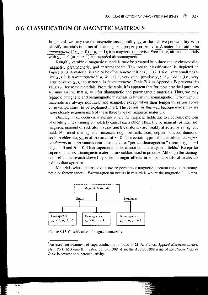
Roughly speaking, magnetic materials may be grouped into three major classes: dia-magnetic, paramagnetic, and ferromagnetic. This rough classification is depicted inFigure 8.13. A material is said to be diamagnetic if it has \xr S 1 (i.e., very small nega-tive Xm)- It is paramagnetic if pr S 1 (i.e., very small positive xm)- If Mr ^ 1 (i-e-> verYlarge positive xm)> the material is ferromagnetic. Table B.3 in Appendix B presents thevalues fir for some materials. From the table, it is apparent that for most practical purposeswe may assume that \ir — 1 for diamagnetic and paramagnetic materials. Thus, we mayregard diamagnetic and paramagnetic materials as linear and nonmagnetic. Ferromagneticmaterials are always nonlinear and magnetic except when their temperatures are abovecurie temperature (to be explained later). The reason for this will become evident as wemore closely examine each of these three types of magnetic materials.
Diamagnetism occurs in materials where the magnetic fields due to electronic motionsof orbiting and spinning completely cancel each other. Thus, the permanent (or intrinsic)magnetic moment of each atom is zero and the materials are weakly affected by a magneticfield. For most diamagnetic materials (e.g., bismuth, lead, copper, silicon, diamond,sodium chloride), xm is of the order of - 1(T5. In certain types of materials called super-conductors at temperatures near absolute zero, "perfect diamagnetism" occurs: xm
= ~ 1or jjir = 0 and B = 0. Thus superconductors cannot contain magnetic fields.2 Except forsuperconductors, diamagnetic materials are seldom used in practice. Although the diamag-netic effect is overshadowed by other stronger effects in some materials, all materialsexhibit diamagnetism.
Materials whose atoms have nonzero permanent magnetic moment may be paramag-netic or ferromagnetic. Paramagnetism occurs in materials where the magnetic fields pro-
Magnetic Materials
Linear
Diamagnetics
Xm<0, M r s 1.0
Paramagnetics
Xm > 0, fir a
Nonlinear
Ferromagnetics
Xm » 0, nr a>
Figure 8.13 Classification of magnetic materials.
2An excellent treatment of superconductors is found in M. A. Plonus, Applied Electromagnetics.New York: McGraw-Hill, 1978, pp. 375-388. Also, the August 1989 issue of the Proceedings ofIEEE is devoted to superconductivity.

328 Magnetic Forces, Materials, and Devices
duced by orbital and spinning electrons do not cancel completely. Unlike diamagnetism,paramagnetism is temperature dependent. For most paramagnetic materials (e.g., air, plat-inum, tungsten, potassium), \m is ofthe order +10~5 to +10~3 and is temperature depen-dent. Such materials find application in masers.
Ferromagnetism occurs in materials whose atoms have relatively large permanentmagnetic moment. They are called ferromagnetic materials because the best knownmember is iron. Other members are cobalt, nickel, and their alloys. Ferromagnetic materi-als are very useful in practice. As distinct from diamagnetic and paramagnetic materials,ferromagnetic materials have the following properties:
1. They are capable of being magnetized very strongly by a magnetic field.2. They retain a considerable amount of their magnetization when removed from the
field.3. They lose their ferromagnetic properties and become linear paramagnetic materials
when the temperature is raised above a certain temperature known as the curie tem-perature. Thus if a permanent magnet is heated above its curie temperature (770°Cfor iron), it loses its magnetization completely.
4. They are nonlinear; that is, the constitutive relation B = /xo/irH does not hold forferromagnetic materials because \x.r depends on B and cannot be represented by asingle value.
Thus, the values of /xr cited in Table B.3 for ferromagnetics are only typical. For example,for nickel \x.r = 50 under some conditions and 600 under other conditions.
As mentioned in Section 5.9 for conductors, ferromagnetic materials, such as iron andsteel, are used for screening (or shielding) to protect sensitive electrical devices from dis-turbances from strong magnetic fields. A typical example of an iron shield is shown inFigure 8.14(a) where the compass is protected. Without the iron shield, the compass givesan erroneous reading due to the effect of the external magnetic field as in Figure 8.14(b).For perfect screening, it is required that the shield have infinite permeability.
Even though B = juo(H + M) holds for all materials including ferromagnetics, therelationship between B and H depends on previous magnetization of a ferromagnetic
Iron shield
(N-»-) *s I)(
(b)
Figure 8.14 Magnetic screening: (a) iron shield protecting a small compass,(b) compass gives erroneous reading without the shield.

8.6 CLASSIFICATION OF MAGNETIC MATERIALS 329
material—its "magnetic history." Instead of having a linear relationship between B and H(i.e., B = fiH), it is only possible to represent the relationship by a magnetization curve orB-H curve.
A typical B-H curve is shown in Figure 8.15. First of all, note the nonlinear relation-ship between B and H. Second, at any point on the curve, fi is given by the ratio B/H andnot by dB/dH, the slope of the curve.
If we assume that the ferromagnetic material whose B-H curve.in Figure 8.15 is ini-tially unmagnetized, as H increases (due to increase in current) from O to maximumapplied field intensity Hm.dX, curve OP is produced. This curve is referred to as the virgin orinitial magnetization curve. After reaching saturation at P, if H is decreased, B does notfollow the initial curve but lags behind H. This phenomenon of B lagging behind H iscalled hysteresis (which means "to lag" in Greek).
If H is reduced to zero, B is not reduced to zero but to Bn which is referred to as thepermanent flux density. The value of Br depends on //max, the maximum applied field in-tensity. The existence of Br is the cause of having permanent magnets. If H increases neg-atively (by reversing the direction of current), B becomes zero when H becomes Hc, whichis known as the coercive field intensity. Materials for which Hc is small are said to be mag-netically hard. The value of Hc also depends on Hmm.
Further increase in H in the negative direction to reach Q and a reverse in its directionto reach P gives a closed curve called a hysteresis loop. The shape of hysteresis loopsvaries from one material to another. Some ferrites, for example, have an almost rectangu-lar hysteresis loop and are used in digital computers as magnetic information storagedevices. The area of a hysteresis loop gives the energy loss (hysteresis loss) per unitvolume during one cycle of the periodic magnetization of the ferromagnetic material. Thisenergy loss is in the form of heat. It is therefore desirable that materials used in electricgenerators, motors, and transformers should have tall but narrow hysteresis loops so thathysteresis losses are minimal.
Initialmagnetizationcurve
Figure 8.15 Typical magnetization (B-H) curve.

330 Magnetic Forces, Materials, and Devices
EXAMPLE 8.7Region 0 ^ z — 2 m is occupied by an infinite slab of permeable material (/xr = 2.5). IfB = \0y&x — 5xay mWb/m2 within the slab, determine: (a) J, (b) ih, (c) M, (d) Kb onz = 0.
Solution:
(a) By definition,
J = V X H = V X B 1
4ir X 10"'(2.5) V dx dy
dB,a
106
( - 5 - 10)10 X = -4.775azkA/mz
(b) h = XmJ = (Mr - DJ = 1.5(-4.775az) • 103
= -7.163a7kA/m2
(c) M = XmH =B 1.5(10yax - 5xay) • 10
Air X 10"7(2.5)
- 3
= 4.775vax - 2.387xav kA/m(d) Kb = M X an. Since z = 0 is the lower side of the slab occupying 0 < z ^ 2,an = — az. Hence,
Kb = (4.775jax - 2.387xav) X (-a,)= 2.387xax + 4.775jaT'kA/m
PRACTICE EXERCISE 8.7
In a certain region (/i = 4.6/x0),
find: (a) Xm, (b) H, (c) M.
B = We~\ mWb/m2
Answer: (a) 3.6, (b) mOe^a, A/m, (c) 6228e"yaz A/m.
8.7 MAGNETIC BOUNDARY CONDITIONS
We define magnetic boundary conditions as the conditions that H (or B) field must satisfyat the boundary between two different media. Our derivations here are similar to those inSection 5.9. We make use of Gauss's law for magnetic fields
B • dS = 0 (8.38)
8.7 MAGNETIC BOUNDARY CONDITIONS 331
and Ampere's circuit law
H • d\ = I 3.39)
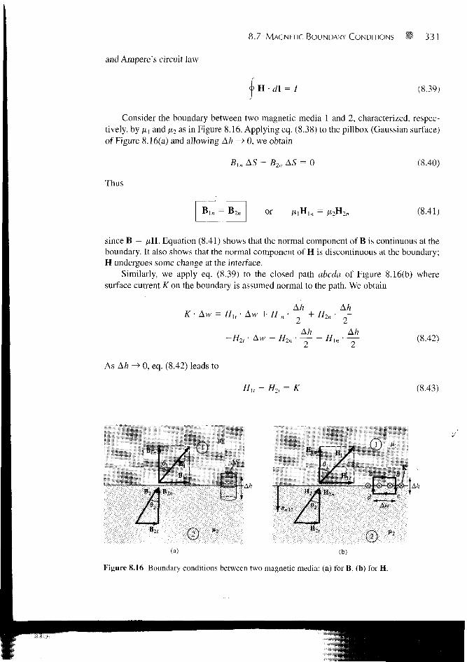
Consider the boundary between two magnetic media 1 and 2, characterized, respec-tively, by ix{ and /x2 as in Figure 8.16. Applying eq. (8.38) to the pillbox (Gaussian surface)of Figure 8.16(a) and allowing Ah —> 0, we obtain
ln AS - B2n AS = (8.40)
Thus
or (8.41)
since B = ^H. Equation (8.41) shows that the normal component of B is continuous at theboundary. It also shows that the normal component of H is discontinuous at the boundary;H undergoes some change at the interface.
Similarly, we apply eq. (8.39) to the closed path abcda of Figure 8.16(b) wheresurface current K on the boundary is assumed normal to the path. We obtain
Ah\n ' ~~Z I" H2n
Ah
As Ah -> 0, eq. (8.42) leads to
H Aw H M H Ak
Hit H2, — K
(8.42)
(8.43)
fH,
(a) (b)
Figure 8.16 Boundary conditions between two magnetic media: (a) for B, (b) for H.

332 Magnetic Forces, Materials, and Devices
This shows that the tangential component of H is also discontinuous. Equation (8.43) maybe written in terms of B as
— = K (8.44)
In the general case, eq. (8.43) becomes
(H, - H2) X an l2 = K (8.45)
where anl2 is a unit vector normal to the interface and is directed from medium 1 tomedium 2. If the boundary is free of current or the media are not conductors (for K is freecurrent density), K — 0 and eq. (8.43) becomes
I H l r - H2, or (8.46)
Thus the tangential component of H is continuous while that of B is discontinuous at theboundary.
If the fields make an angle 6 with the normal to the interface, eq. (8.41) results in
cos 0[ = Bln = B2n = B2 cos
while eq. (8.46) produces
Mi
B2
sin 0, = Hu = H2t = — sin 62
(8.47)
(8.48)
Dividing eq. (8.48) by eq. (8.47) gives
r tan I
tan02(8.49)
which is [similar to eq. (5.65)] the law of refraction for magnetic flux lines at a boundarywith no surface current.
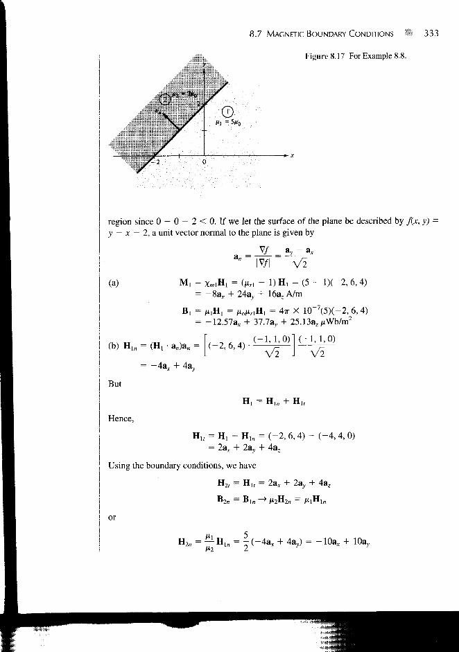
EXAMPLE 8.8 Given that H! = -2a x + 6ay + 4az A/m in region y - x - 2 < 0 where /*] = 5/*0, cal-culate
(a) M, and B,
(b) H2 and B2 in region y - x - 2 > 0 where ju2 = 2;ito
Solution:
Since j - x - 2 = 0 i s a plane, y - x < 2 o r y < x + 2 i s region 1 in Figure 8.17. Apoint in this region may be used to confirm this. For example, the origin (0, 0) is in this
8.7 MAGNETIC BOUNDARY CONDITIONS ;- 333
Figure 8.17 For Example 8.8.
region since 0 - 0 - 2 < 0. If we let the surface of the plane be described by j{x, y) =y — x — 2, a unit vector normal to the plane is given by
(a) M,
= ay - a*
V~2= ( / M - 1)H, = ( 5 - lX-2 ,6 ,4 )
+ 24av, + 16a7 A/m
(b) HlB = (H! • aB)aB = | ( -2 ,6 ,4)
B, = ^JHJ = Aio/nnH, = 4TT X 10"7(5)(-2, 6,4)= -12.57a* + 37.7ay + 25.13a,/iWb/m2
( -1 ,1 ,0)1 ( -1 ,1 ,0)
Vl J V2
But
Hence,
— Hln + Hlf
Ult = H, - Hln = (-2, 6, 4) - (-4,4, 0)= 2ar + 2av + 4a7
Using the boundary conditions, we have
H2, = H u = 4az
or
H2n = — HIB = | ( -4a , + 4ay) = -10a* + 10a,

334 f i Magnetic Forces, Materials, and Devices
Thus
H 2 = H2n + H2, = - 8 a x + 12av + 4a. A/m
and
B 2 = fi2H2 = jxojxr2n2 = (4TT X 10 7 ) (2 ) ( -8 , 12, 4)= -20 .11a , + 30.16ay + 10.05a.
PRACTICE EXERCISE 8.8
Region 1, described by 3x + Ay > 10, is free space whereas region 2, described by3x + Ay < 10, is a magnetic material for which /* = J OJU0. Assuming that theboundary between the material and free space is current free find B7 if B, =0.1a,+ 0.4av +0.2a. Wb/m2
Answer: -1.052a, + 1.264a,. + 2az Wb/m2
EXAMPLE 8.9 The xy-plane serves as the interface between two different media. Medium 1 (z < 0) isfilled with a material whose Mr = 6, and medium 2 (z > 0) is filled with a material whoseHr = 4. If the interface carries current (1/Mo) av mA/m, and B2 = 5a, + 8a mWb/m2 findHiandB,.
Solution:
In the previous example K = 0, so eq. (8.46) was appropriate. In this example, however,K # 0, and we must resort to eq. (8.45) in addition to eq. (8.41). Consider the problem asillustrated in Figure 8.18. Let B, = (Bx, By, Bz) in mWb/m2.
But
[2) nr2=4
Bin = B2 n
(5a,
K-» -y
B7 = 8
mA/m
Figure 8.18 For Example 8.9.
(8.8.1)
(8.8.2)

8.7 MAGNETIC BOUNDARY CONDITIONS *> 335
and
H, =B, 1
{Bxax + Byay + Bzaz) mA/m (8.8.3)
Having found the normal components, we can find the tangential components using
(H, - H2) X anl2 = K
or
H, X anl2 = H2 X aBl2 + K (8.8.4)
Substituting eqs. (8.8.2) and (8.8.3) into eq. (8.8.4) gives
— ( B A + 5vay + Bzaz) X az = —- (5a, + 8az) X a, + — av6^ ' 4/x M
Equating components yields
By = 0, :
From eqs. (8.8.1) and (8.8.5),
- 54
o r
6T4
B, = 1.5a,, + 8azmWb/m2
H, = — = — (0.25ax + 1.33a,) mA/mMl Mo
and
(8.8.5)
H2 = — (1.25a* + 2az) mA/mMo
Note that Hlx is (1//O mA/m less than H2x due to the current sheet and also thatBin = B2n.
PRACTICE EXERCISE 8.9
A unit normal vector from region 2 {ft, = 2MO) to region 1 {ft, = Mo) is a«2i =
(6ax + 2a, - 3az)/7. If H, = \0ax + ay + 12az A/m and H2 =4az A/m, determine
(a) H ^
(b) The surface current density K on the interface
(c) The angles Bj and B2 make with the normal to the interface.
- 5ay +
Answer: (a) 5.833, (b) 4.86a* - 8.64a. + 3.95a, A/m, (c)76.27°, 77.62°.
336 Magnetic Forces, Materials, and Devices
8.8 INDUCTORS AND INDUCTANCES
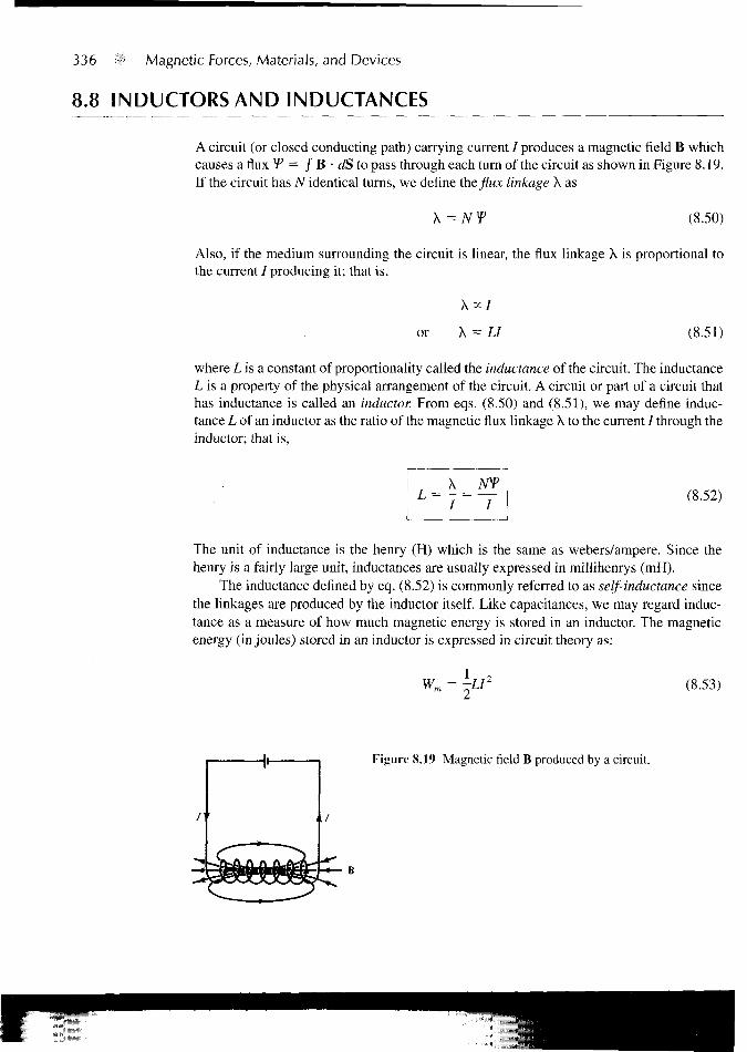
A circuit (or closed conducting path) carrying current / produces a magnetic field B whichcauses a flux ¥* = J B • dS to pass through each turn of the circuit as shown in Figure 8.19.If the circuit has N identical turns, we define the flux linkage X as
X = NY (8.50)
Also, if the medium surrounding the circuit is linear, the flux linkage X is proportional tothe current / producing it; that is,
or X = (8.51)
where Lisa constant of proportionality called the inductance of the circuit. The inductanceL is a property of the physical arrangement of the circuit. A circuit or part of a circuit thathas inductance is called an inductor. From eqs. (8.50) and (8.51), we may define induc-tance L of an inductor as the ratio of the magnetic flux linkage X to the current / through theinductor; that is,
X(8.52)
The unit of inductance is the henry (H) which is the same as webers/ampere. Since thehenry is a fairly large unit, inductances are usually expressed in millihenrys (mH).
The inductance denned by eq. (8.52) is commonly referred to as self-inductance sincethe linkages are produced by the inductor itself. Like capacitances, we may regard induc-tance as a measure of how much magnetic energy is stored in an inductor. The magneticenergy (in joules) stored in an inductor is expressed in circuit theory as:
Wm = ^L (8.53)
Figure 8.19 Magnetic field B produced by a circuit.

8.8 INDUCTORS AND INDUCTANCES 337
or
L — — (8.54)
Thus the self-inductance of a circuit may be defined or calculated from energy considera-tions.
If instead of having a single circuit we have two circuits carrying current I\ and I2 asshown in Figure 8.20, a magnetic interaction exists between the circuits. Four componentfluxes ^ n , f|2, V 21, and f22
a r e produced. The flux "f \2, for example, is the flux passingthrough circuit 1 due to current I2 in circuit 2. If B2 in the field due to I2 and S\ is the areaof circuit 1, then
(8.55)
We define the mutual inductance Mn as the ratio of the flux linkage X12 = N{fu on circuit1 to current I2, that is,
! .. x1212 = T =
I i
(8.56)
Similarly, the mutual inductance M2\ is defined as the flux linkages of circuit 2 per unitcurrent /,; that is,
M7I =h /,
(8.57a)
It can be shown by using energy concepts that if the medium surrounding the circuits islinear (i.e., in the absence of ferromagnetic material),
M12 = M2{ (8.57b)
The mutual inductance Mi2 or M2l is expressed in henrys and should not be confused withthe magnetization vector M expressed in amperes/meter.
Figure 8.20 Magnetic interaction betweentwo circuits.
338 B Magnetic Forces, Materials, and Devices
We define the self-inductance of circuits 1 and 2, respectively, as
L = x,, _ w(8.58)
and
U = x,22 (8.59)
where V, = + + ¥^2-The total energy in the magnetic field is thesum of the energies due to Lh L2, andMI2 (orM21); that is,
Wm = W2 + W12
2 + ~L2I22 (8.60)
The positive sign is taken if currents /] and I2 flow such that the magnetic fields of the twocircuits strengthen each other. If the currents flow such that their magnetic fields opposeeach other, the negative sign is taken.
As mentioned earlier, an inductor is a conductor arranged in a shape appropriate tostore magnetic energy. Typical examples of inductors are toroids, solenoids, coaxial trans-mission lines, and parallel-wire transmission lines. The inductance of each of these induc-tors can be determined by following a procedure similar to that taken in determining thecapacitance of a capacitor. For a given inductor, we find the self-inductance L by takingthese steps:
1. Choose a suitable coordinate system.2. Let the inductor carry current /.3. Determine B from Biot-Savart's law (or from Ampere's law if symmetry exists)
and calculate f from V = / B • dS.X NY
4. Finally find L from L = — = .
The mutual inductance between two circuits may be calculated by taking a similar proce-dure.
In an inductor such as a coaxial or a parallel-wire transmission line, the inductanceproduced by the flux internal to the conductor is called the internal inductance L-m whilethat produced by the flux external to it is called external inductance Lext. The total induc-tance L is
Mn ' ^e\l
Just as it was shown that for capacitors
eRC = -
a
(8.61)
(6.35)

it can be shown that
LexlC =
8.9 MAGNETIC ENERGY -.-> 339
(8.62)
Thus Lext may be calculated using eq. (8.62) if C is known.A collection of formulas for some fundamental circuit elements is presented in Table
8.3. All formulas can be derived by taking the steps outlined above.3
8.9 MAGNETIC ENERGY
Just as the potential energy in an electrostatic field was derived as
eE dvWE = - D • E dv = ~ (4.96)
we would like to derive a similar expression for the energy in a magnetostatic field. Asimple approach is using the magnetic energy in the field of an inductor. From eq. (8.53),
(8.53)
The energy is stored in the magnetic field B of the inductor. We would like to expresseq. (8.53) in terms of B or H.
Consider a differential volume in a magnetic field as shown in Figure 8.21. Let thevolume be covered with conducting sheets at the top and bottom surfaces with current A/.
conductingsheets
Figure 8.21 A differential volumein a magnetic field.
'Additional formulas can be found in standard electrical handbooks or in H. Knoepfel, Pulsed HighMagnetic Fields. Amsterdam: North-Holland, 1970, pp. 312-324.

o
TABLE 8.3 A Collection of Formulas for Inductance of Common Elements
1. Wire
L
L =877
2.
3.
Hollow
L = —2TI
€»a
Parallel
L = —-IT
cylinder
' \ a
wires
f J- l n -
(3
4. Coaxial conductor
L = In -7T a
5. Circular loop
ii ^ 1 In — — 22TT \ d
€ = 27rpo, po » d
6. Solenoid
L =
7. Torus (of circular cross section)
L = voN2[Po - Vp2
o - a2]2.1
8. Sheet
L = /to 2€ /«

8.9 MAGNETIC ENERGY 341
We assume that the whole region is filled with such differential volumes. From eq. (8.52),each volume has an inductance
AL =AT tiHAxAz
A/ A/
where A/ = H Ay. Substituting eq. (8.63) into eq. (8.53), we have
AWm = -AL A/2 = - iiH2 Ax Ay Az
or
_ l 2m j
The magnetostatic energy density wm (in J/m3) is defined as
AWm 1 .. ,wm = lim
Av->0 Av
Hence,
1 , 1 B2
2 2 2/*
Thus the energy in a magnetostatic field in a linear medium is
Wm= wmdv
or
which is similar to eq. (4.96) for an electrostatic field.
(8.63)
(8.64)
(8.65)
(8.66)
EXAMPLE 8.10Calculate the self-inductance per unit length of an infinitely long solenoid.
Solution:
We recall from Example 7.4 that for an infinitely long solenoid, the magnetic flux insidethe solenoid per unit length is
B = nH = uln

342 Magnetic Forces, Materials, and Devices
where n = N/€ = number of turns per unit length. If S is the cross-sectional area of the so-lenoid, the total flux through the cross section is
Y = BS =
Since this flux is only for a unit length of the solenoid, the linkage per unit length is
X' = - = nV = im2IS
and thus the inductance per unit length is
L X' ,
V = /xn2S H/m
PRACTICE EXERCISE 8.10
A very long solenoid with 2 X 2 cm cross section has an iron core (p,r - 1000) and4000 turns/meter. If it carries a current of 500 mA, find
(a) Its self-inductance per meter
(b) The energy per meter stored in its field
Answer: (a) 8.042 H/m, (b) 1.005 J/m.
EXAMPLE 8.11 Determine the self-inductance of a coaxial cable of inner radius a and outer radius b.
Solution:
The self-inductance of the inductor can be found in two different ways: by taking the foursteps given in Section 8.8 or by using eqs. (8.54) and (8.66).
Method 1: Consider the cross section of the cable as shown in Figure 8.22. We recallfrom eq. (7.29) that by applying Ampere's circuit law, we obtained for region1 (0 < p < a),
and for region 2 (a < p < b),
B , - - j a<*2-wa

8.9 MAGNETIC ENERGY 343
© z-axis
(a) (b)
Figure 8.22 Cross section of the coaxial cable: (a) for region 1,0 < p < a, (b) for region 2, a < p < b; for Example 8.11.
We first find the internal inductance Lin by considering the flux linkages due to the innerconductor. From Figure 8.22(a), the flux leaving a differential shell of thickness dp is
dYi = 5, dp dz = - ~ dp dz2ira
The flux linkage is dxPl multiplied by the ratio of the area within the path enclosing the fluxto the total area, that is,
because / is uniformly distributed over the cross section for d.c. excitation. Thus, the totalflux linkages within the differential flux element are
flip dp dz
lira2 a2
For length € of the cable,
X, = r dp dz8TT
/ 8TT
The internal inductance per unit length, given by
m i H/m
(8.11.1)
(8.11.2)
is independent of the radius of the conductor or wire. Thus eqs. (8.11.1) and (8.11.2) are alsoapplicable to finding the inductance of any infinitely long straight conductor of finite radius.

344 Magnetic Forces, Materials, and Devices
We now determine the external inductance Lext by considering the flux linkagesbetween the inner and the outer conductor as in Figure 8.22(b). For a differential shell ofthickness dp,
df2 = B2 dp dz2-Kp
dp dz
In this case, the total current / is enclosed within the path enclosing the flux. Hence,
X, =p=a Jz=0
al dp dz i"/€ , b= In —
2irp 2-K a
_ \ 2 _ ^ bL e x t ~ I ~ 2* a
Thus
\
or the inductance per length is
H/m
Method 2: It is easier to use eqs. (8.54) and (8.66) to determine L, that is,
2W
where
or L =
1 f B1
I H dv = —dv2
Hence
2 [B\ 2T2 2
— — p dp d(j) dz4TT a
= - ^ - r dz dct> p 3 dp =0 J0 J0
8TT
^ P 6?P d<t> dz

8.9 MAGNETIC ENERGY • 345
and
as obtained previously.
PRACTICE EXERCISE 8.11
Calculate the self-inductance of the coaxial cable of Example 8.11 if the inner con-ductor is made of an inhomogeneous material having a = 2aJ{\ + p).
aot uj \ b (1 + b)Answer: 1 In In
8TT IT I a (1 + a)
EXAMPLE 8.12 Determine the inductance per unit length of a two-wire transmission line with separationdistance d. Each wire has radius a as shown in Figure 6.37.
Solution:
We use the two methods of the last example.
Method 1: We determine Lin just as we did in the last example. Thus for region0<p<a,we obtain
_ alt
as in the last example. For region a < p < d - a, the flux linkages between the wires arecd—a /*€ T rt) jX2 =
The flux linkages produced by wire 1 are
dp dz = —- In2TT a
X, + \? =alt alt d- a
1 In8TT 2TT a
By symmetry, the same amount of flux produced by current —/ in wire 2. Hence the totallinkages are
X 2(Xi+X2) [If d 5s> a, the self-inductance per unit length is
H/m

346 11 Magnetic Forces, Materials, and Devices
Method 2: From the last example,
Lm ~ 8
Now
B2dv 1 {[[ ii2!2
L e x t I2) 2» l \
dz
^ p dp d(j) dz
d—a
2ir a
Since the two wires are symmetrical,
L = 2 (Lin + Lext)
as obtained previously.
PRACTICE EXERCISE 8.12
Two #10 copper wires (2.588 mm in diameter) are placed parallel in air with a sepa-ration distance d between them. If the inductance of each wire is 1.2 jiiH/m, calculate
(a) Lin and Lext per meter for each wire
(b) The separation distance d
Answer: (a) 0.05,1.15 juH/m, (b) 40.79 cm.
EXAMPLE 8.13Two coaxial circular wires of radii a and b(b > a) are separated by distance h(h ^> a, b)as shown in Figure 8.23. Find the mutual inductance between the wires.
Solution:
Let current /, flow in wire 1. At an arbitrary point P on wire 2, the magnetic vector poten-tial due to wire 1 is given by eq. (8.21a), namely
A , =A[h2 + b2f2
If/i » b
b

8.10 MAGNETIC CIRCUITS 347
Figure 8.23 Two coaxial circular wires; for Example8.13.
Hence,
and
u;,21.2
• d\2 =4/r'
/x7r/,a b
~2h3
lbl
PRACTICE EXERCISE 8.13
Find the mutual inductance of two coplanar concentric circular loops of radii 2 mand 3 m.
Answer: 2.632 /*H.
8.10 MAGNETIC CIRCUITS
The concept of magnetic circuits is based on solving some magnetic field problems usingcircuit approach. Magnetic devices such as toroids, transformers, motors, generators, andrelays may be considered as magnetic circuits. The analysis of such circuits is made simpleif an analogy between magnetic circuits and electric circuits is exploited. Once this is done,we can directly apply concepts in electric circuits to solve their analogous magnetic circuits.
The analogy between magnetic and electric circuits is summarized in Table 8.4 andportrayed in Figure 8.24. The reader is advised to pause and study Table 8.4 and Figure8.24. First, we notice from the table that two terms are new. We define the magnetomotiveforce (mmf) 9* (in ampere-turns) as
(8.67)

348 Magnetic Forces, Materials, and Devices
TABLE 8.4 Analogy between Electric and MagneticCircuits
Electric
Conductivity a
Field intensity E
Current / = / J • dS
Current density J = — = oE
Electromotive force (emf) VResistance R
Conductance G = —R
V (Ohm's law R = — = —
or V = E( = IR
Kirchoff's laws:E / = 0
J. V - 2 RI = 0
Magnetic
Permeability /j
Field intensity H
Magnetic flux V = / B • dS
Flux density B = — = fiH
Magnetomotive force (mmf) 9Reluctance 2ft
Permeance 9* = —gft
Ohm's law gft = — = —
or 9 = Hi = » = Nl
Kirchhoff's laws:
The source of mmf in magnetic circuits is usually a coil carrying current as in Figure 8.24.We also define reluctance 2ft (in ampere-turns/weber) as
(8.68)
where € and S are, respectively, the mean length and the cross-sectional area of the mag-netic core. The reciprocal of reluctance is permeance (3>. The basic relationship for circuitelements is Ohm's law (V = IR):
(8.69)
Based on this, Kirchhoff's current and voltage laws can be applied to nodes and loops of agiven magnetic circuit just as in an electric circuit. The rules of adding voltages and for
Figure 8.24 Analogy between(a) an electric circuit, and (b) amagnetic circuit.
(a) (b)

8.11 FORCE ON MAGNETIC MATERIALS 349
combining series and parallel resistances also hold for mmfs and reluctances. Thus for nmagnetic circuit elements in series
and
3? = 3%,
For n magnetic circuit elements in parallel,
and
(8.70)
(8.71)
(8.72)
(8.73)
Some differences between electric and magnetic circuits should be pointed out. Unlikean electric circuit where current / flows, magnetic flux does not flow. Also, conductivity ais independent of current density J in an electric circuit whereas permeability JX varies withflux density B in a magnetic circuit. This is because ferromagnetic (nonlinear) materialsare normally used in most practical magnetic devices. These differences notwithstanding,the magnetic circuit concept serves as an approximate analysis of practical magneticdevices.
8.11 FORCE ON MAGNETIC MATERIALS
It is of practical interest to determine the force that a magnetic field exerts on a piece ofmagnetic material in the field. This is useful in electromechanical systems such as electro-magnets, relays, rotating machines, and magnetic levitation. Consider, for example, anelectromagnet made of iron of constant relative permeability as shown in Figure 8.25. Thecoil has N turns and carries a current /. If we ignore fringing, the magnetic field in the airgap is the same as that in iron (Bln = B2n). To find the force between the two pieces of iron,we calculate the change in the total energy that would result were the two pieces of themagnetic circuit separated by a differential displacement d\. The work required to effect
dlA
Figure 8.25 An electromagnet.
/2F

350 Magnetic Forces, Materials, and Devices
the displacement is equal to the change in stored energy in the air gap (assuming constantcurrent), that is
1 B-Fdl = dWm = 2 | Sdl
2 Mo(8.74)
where S is the cross-sectional area of the gap, the factor 2 accounts for the two air gaps, andthe negative sign indicates that the force acts to reduce the air gap (or that the force is at-tractive). Thus
F = -2B2S
(8.75)
Note that the force is exerted on the lower piece and not on the current-carrying upperpiece giving rise to the field. The tractive force across a single gap can be obtained fromeq. (8.75) as
F = -B2S
(8.76)
Notice the similarity between eq. (8.76) and that derived in Example 5.8 for electrostaticcase. Equation (8.76) can be used to calculate the forces in many types of devices includ-ing relays, rotating machines, and magnetic levitation. The tractive pressure (in N/m2) in amagnetized surface is
PF
S
B1
(8.77)
which is the same as the energy density wm in the air gap.
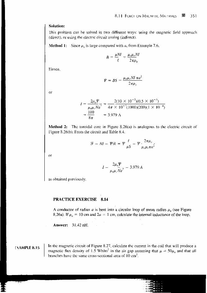
EXAMPLE 8.14The toroidal core of Figure 8.26(a) has po = 10 cm and a circular cross section witha = 1 cm. If the core is made of steel (/x = 1000 /io) and has a coil with 200 turns, calcu-late the amount of current that will produce a flux of 0.5 mWb in the core.
(a) (b)
Figure 8.26 (a) Toroidal core of Example 8.14; (b) its equivalent elec-tric circuit analog.
8.11 FORCE ON MAGNETIC MATERIALS 351
Solution:
This problem can be solved in two different ways: using the magnetic field approach(direct), or using the electric circuit analog (indirect).
Method 1: Since p0 is large compared with a, from Example 7.6,
UNI _ floHrNI
Hence,
B =
= BS =HolirNI tea
2TTP0
or
8TT
_ 2(10 X 10~2)(0.5 X 10~3)
~ 4TT X 10~7(1000)(200)(l X 10
= 3.979 A
Method 2: The toroidal core in Figure 8.26(a) is analogous to the electric circuit ofFigure 8.26(b). From the circuit and Table 8.4.
or
/ = = 3.979 A
as obtained previously.
PRACTICE EXERCISE 8.14
A conductor of radius a is bent into a circular loop of mean radius po (see Figure8.26a). If p0 = 10 cm and 2a - 1 cm, calculate the internal inductance of the loop.
Answer: 31.42 nH.
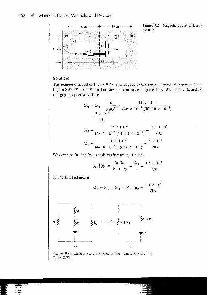
EXAMPLE 8.15 In the magnetic circuit of Figure 8.27, calculate the current in the coil that will produce amagnetic flux density of 1.5 Wb/m in the air gap assuming that fi = 50/xo and that allbranches have the same cross-sectional area of 10 cm2.
352 =* Magnetic Forces, Materials, and Devices
Figure 8.27 Magnetic circuit of Exam-ple 8.15.
10 cm
Solution:
The magnetic circuit of Figure 8.27 is analogous to the electric circuit of Figure 8.28. InFigure 8.27, Sft,, 2ft2, 2/l3, and <3la are the reluctances in paths 143, 123, 35 and 16, and 56(air gap), respectively. Thus
(3i,='3i7 =
3 X 10s
30 X 10~z
(4TT X 10 7)(50)(10 X
20TT
9 X 10"3 (4TT X 10~7)(50)(10 X
1 X 10~2
0.9 X 10s
20TT
5 X 10,8
'J"a ~ (4,r x 10"7)(l)(10 X 10~4) ~ 20ir
We combine 91, and 9l2 as resistors in parallel. Hence,
„ ,,„ 2ft,2ft7 2/1, 1.5 X 10⁸
The total reluctance is
20x
7.4 X 108
91,
(a) (b)
Figure 8.28 Electric circuit analog of the magnetic circuit inFigure 8.27.

8.11 FORCE ON MAGNETIC MATERIALS 353
The
But
mmf is
r.-r = BaS. Hence
i a
1 —
= 44
52ft
N.16
T
A
= NI = YJ
1.5 X 10 X 10~4 X 7.4 X 108
400 X 20TT
PRACTICE EXERCISE 8.15
The toroid of Figure 8.26(a) has a coil of 1000 turns wound on its core. Ifp 0 = 10 cm and a = 1 cm, what current is required to establish a magnetic flux of0.5 mWb
(a) If the core is nonmagnetic
(b) If the core has /xr = 500
Answer: (a) 795.8 A, (b) 1.592 A.
EXAMPLE 8.16 A U-shaped electromagnet shown in Figure 8.29 is designed to lift a 400-kg mass (whichincludes the mass of the keeper). The iron yoke (jxr = 3000) has a cross section of 40 cm2
and mean length of 50 cm, and the air gaps are each 0.1 mm long. Neglecting the reluc-tance of the keeper, calculate the number of turns in the coil when the excitation currentis 1 A.
Solution:
The tractive force across the two air gaps must balance the weight. Hence
F = 2(B2
aS)= mg
NI Figure 8.29 U-shaped electromagnet; for Example 8.16.
- iron yoke
- keeper
' weisht

354 Magnetic Forces, Materials, and Devices
or
But
Since
mgno _ 400 X 9.8 X 4TT X 10 - i
S 40 X
Bn = 1.11 Wb/m2
cm = ZJL =ta 2 X 0.1 10- 3 10b
Air X 10 7 X 40 X 10 4
50 X 10~2
48TT
4TT X 10"' X 3000 X 40 X 10~
3? = NI = —NI6 + 5 11
5 X 10"
48TT
P-o
11 L
7V= 162
11 X 1.11 X 0.1 X 10
6 X 4TT X 10~7 X 1
PRACTICE EXERCISE 8.16
Find the force across the air gap of the magnetic circuit of Example 8.15.
Answer: 895.2 N.
SUMMARY 1. The Lorentz force equation
F = g(E + u X B) = mdudt
relates the force acting on a particle with charge Q in the presence of EM fields. It ex-presses the fundamental law relating EM to mechanics.
2. Based on the Lorentz force law, the force experienced by a current element Idl in amagnetic field B is
dV = Idl X B
From this, the magnetic field B is defined as the force per unit current element.

SUMMARY • 355
3. The torque on a current loop with magnetic moment m in a uniform magnetic field B is
T = m X B = ISan X B
4. A magnetic dipole is a bar magnet or a small filamental current loop; it is so called dueto the fact that its B field lines are similar to the E field lines of an electric dipole.
5. When a material is subjected to a magnetic field, it becomes magnetized. The magne-tization M is the magnetic dipole moment per unit volume of the material. For linearmaterial,
where \m is the magnetic susceptibility of the material.6. In terms of their magnetic properties, materials are either linear (diamagnetic or para-
magnetic) or nonlinear (ferromagnetic). For linear materials,
B = ,xH = = /xo(l + + M)
where /x = permeability and \xr = \il\xo = relative permeability of the material. Fornonlinear material, B = fi(H) H, that is, JX does not have a fixed value; the relationshipbetween B and H is usually represented by a magnetization curve.
7. The boundary conditions that H or B must satisfy at the interface between two differ-ent media are
(H, - H2) X anl2 = K or Hu = H2/ if K = 0
where anl2 is a unit vector directed from medium 1 to medium 2.8. Energy in a magnetostatic field is given by
Wm = - | B Udv
For an inductor carrying current /
= Vm 2
Thus the inductance L can be found using
L =B -Hdv
9. The inductance L of an inductor can also be determined from its basic definition: theratio of the magnetic flux linkage to the current through the inductor, that is,
_ X NY~ I ~ I

356 II Magnetic Forces, Materials, and Devices
Thus by assuming current /, we determine B and !P = / B • dS, and finally find
L = NY/I.10. A magnetic circuit can be analyzed in the same way as an electric circuit. We simply
keep in mind the similarity between
= NI= 4> H = TO and V= IR
that is,
Thus we can apply Ohms and Kirchhoff's laws to magnetic circuits just as we applythem to electric circuits.
11. The magnetic pressure (or force per unit surface area) on a piece of magnetic material is
F 1~ = ~S 2
B2
—2/xo
where B is the magnetic field at the surface of the material.
8.1 Which of the following statements are not true about electric force Fe and magnetic forceFm on a charged particle?
(a) E and Fc are parallel to each other whereas B and Fm are perpendicular to each other.
(b) Both Fe and Fm depend on the velocity of the charged particle.
(c) Both Fe and ¥m can perform work.
(d) Both Fc and Fm are produced when a charged particle moves at a constant velocity.
(e) Fm is generally small in magnitude compared to Fe.
(f) Fe is an accelerating force whereas Fm is a purely deflecting force.
8.2 Two thin parallel wires carry currents along the same direction. The force experienced byone due to the other is
(a) Parallel to the lines
(b) Perpendicular to the lines and attractive
(c) Perpendicular to the lines and repulsive
(d) Zero
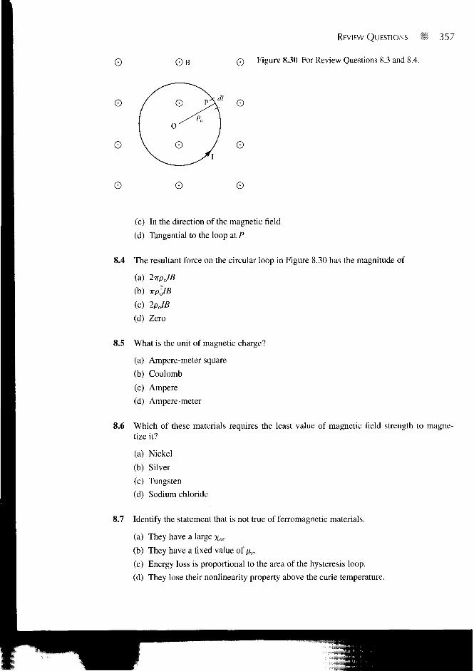
8.3 The force on differential length d\ at point P in the conducting circular loop in Figure8.30 is
(a) Outward along OP
(b) Inward along OP
o
o
o
o
© B
o
REVIEW QUESTIONS #i 357
Q Figure 8.30 For Review Questions 8.3 and 8.4.
O
O
O
(c) In the direction of the magnetic field
(d) Tangential to the loop at P
8.4 The resultant force on the circular loop in Figure 8.30 has the magnitude of
(a) 2wpJB
(b) irpllB
(c) 2PJB
(d) Zero
8.5 What is the unit of magnetic charge?
(a) Ampere-meter square
(b) Coulomb
(c) Ampere
(d) Ampere-meter
8.6 Which of these materials requires the least value of magnetic field strength to magne-tize it?
(a) Nickel
(b) Silver
(c) Tungsten
(d) Sodium chloride
8.7 Identify the statement that is not true of ferromagnetic materials.
(a) They have a large \m.
(b) They have a fixed value of fir.
(c) Energy loss is proportional to the area of the hysteresis loop.
(d) They lose their nonlinearity property above the curie temperature.

358 B Magnetic Forces, Materials, and Devices
8.8 Which of these formulas is wrong?
(a) Bu,= B2n
(b) B2 = Vfi2,, + B\,
(c) // , = //„, + Hu
(d) a,,2i X (H t — H2) = K, where an2i is a unit vector normal to the interface and di-rected from region 2 to region 1.
8.9 Each of the following pairs consists of an electric circuit term and the corresponding mag-netic circuit term. Which pairs are not corresponding?
(a) V and S5
(b) GandSP
(c) e and n
(d) IR and tf9l
(e) 2 / = 0 and 2 f = 0
8.10 A multilayer coil of 2000 turns of fine wire is 20 mm long and has a thickness 5 mm ofwinding. If the coil carries a current of 5 mA, the mmf generated is
(a) lOA-t
(b) 500 A-t
(c) 2000 A-t
(d) None of the above
Answers: 8.1 b,c, 8.2b, 8.3a, 8.4d, 8.5d, 8.6a, 8.7b, 8.8c, 8.9c,d, 8.10a.
PROBLEMS• 8.1 An electron with velocity u = (3ar + 12aY — 4az) X 105m/s experiences no net
J force at a point in a magnetic field B = Wax + 20av + 30a;. mWb/m2. Find E at thatpoint.
8.2 A charged particle of mass 1 kg and charge 2 C starts at the origin with velocity 10az m/sin a magnetic field B = 1 a, Wb/m2. Find the location and the kinetic energy of the parti-cle at t = 2 s.
*8.3 A particle with mass 1 kg and charge 2 C starts from rest at point (2, 3, - 4 ) in a regionwhere E = - 4 a v V/m and B = 5ar Wb/m2. Calculate
(a) The location of the particle at t = I s
(b) Its velocity and K.E. at that location
8.4 A — 2-mC charge starts at point (0, 1, 2) with a velocity of 5ax m/s in a magnetic fieldB = 6av Wb/m . Determine the position and velocity of the particle after 10 s assumingthat the mass of the charge is 1 gram. Describe the motion of the charge.

PROBtEMS ; i 359
Figure 8.31 For Problem 8.5.
*8.5 By injecting an electron beam normally to the plane edge of a uniform field Boaz, elec-trons can be dispersed according to their velocity as in Figure 8.31.
(a) Show that the electrons would be ejected out of the field in paths parallel to the input
beam as shown.
(b) Derive an expression for the exit distance d above entry point.
8.6 Given that B = 6xa^ — 9yay + 3zaz Wb/m2, find the total force experienced by the rec-tangular loop (on z = 0 plane) shown in Figure 8.32.
8.7 A current element of length 2 cm is located at the origin in free space and carries current12 mA along ax. A filamentary current of 15az A is located along x = 3, y = 4. Find theforce on the current filament.
*8.8 Three infinite lines L b L2, and L3 defined by x = 0, y = 0; x = 0, y = 4; x = 3, y = 4,respectively, carry filamentary currents —100 A, 200 A, and 300 A along az. Find theforce per unit length on
(a) L2 due to L,
(b) L[ due to L2
(c) L3 due to Lj
(d) L3 due to Lx and L2. State whether each force is repulsive or attractive.
Figure 8.32 For Problem 8.6.
, 5A
1 2 3

360 Magnetic -: -:es, Materials, and Devices
Figure 8.33 For Problem 8.9.
8.9 A conductor 2 m long carrying 3A is placed parallel to the z-axis at distance p0 = 10 cmas shown in Figure 8.33. If the field in the region is cos (4>/3) ap Wb/m2, how much workis required to rotate the conductor one revolution about the z-axis?
*8.10 A conducting triangular loop carrying a current of 2 A is located close to an infinitelylong, straight conductor with a current of 5 A, as shown in Figure 8.34. Calculate (a) theforce on side 1 of the triangular loop and (b) the total force on the loop.
*8.11 A three-phase transmission line consists of three conductors that are supported at pointsA, B, and C to form an equilateral triangle as shown in Figure 8.35. At one instant, con-ductors A and B both carry a current of 75 A while conductor C carries a return current of150 A. Find the force per meter on conductor C at that instant.
*8.12 An infinitely long tube of inner radius a and outer radius b is made of a conducting magneticmaterial. The tube carries a total current / and is placed along the z-axis. If it is exposed to aconstant magnetic field Boap, determine the force per unit length acting on the tube.
5 A
Figure 8.34 For Problem 8.10.
.©
2m 4 m

2m
B | 7 5 A
PROBLEMS
Figure 8.35 For Problem 8.11.
361
*8.13 An infinitely long conductor is buried but insulated from an iron mass (fi = 2000^,o) asshown in Figure 8.36. Using image theory, estimate the magnetic flux density at point P.
8.14 A galvanometer has a rectangular coil of side 10 by 30 mm pivoted about the center of theshorter side. It is mounted in radial magnetic field so that a constant magnetic field of 0.4Wb/m always acts across the plane of the coil. If the coil has 1000 turns and carriescurrent 2 mA, find the torque exerted on it.
= - 0 . 5 a , mWb/m2at(10, 0, 0). FindB8.15 A small magnet placed at the origin produces Bat
(a) (0 ,3 ,0)
(b) (3, 4, 0)
(c) ( 1 , 1 , - D
8.16 A block of iron (/* = 5000;uo) is placed in a uniform magnetic field with 1.5 Wb/m . Ifiron consists of 8.5 X 1028 atoms/m3, calculate: (a) the magnetization M, (b) the averagemagnetic current.
y
30 mm
o
p%-
0 A
20 mm
iron
20 mm \
*-x
Figure 8.36 For Problem 8.13.
362 Magnetic Forces, Materials, and Devices
8.17 In a certain material for which n = 6.5/x0,
H = 10ax + 25av - 40az A/m
find
(a) The magnetic susceptibility xm of the material
(b) The magnetic flux density B
(c) The magnetization M,
(d) The magnetic energy density
8.18 In a ferromagnetic material (/* = 4.5/to),
B = 4>-a_ mWb/m2
calculate: (a) Xm, (b) H, (c) M, (d) Jb.
8.19 The magnetic field intensity is H = 1200 A/m in a material when B = 2 Wb/m2. WhenH is reduced to 400 A/m, B = 1.4 Wb/m2. Calculate the change in the magnetization M.
8.20 An infinitely long cylindrical conductor of radius a and permeability /xo/xr is placed alongthe z-axis. If the conductor carries a uniformly distributed current / along a7 find M and Jb
for 0 < p < a.
8.21 If M = — {—y&x + xay) in a cube of size a, find Jb. Assume ko is a constant.
*8.22 (a) For the boundary between two magnetic media such as is shown in Figure 8.16, showthat the boundary conditions on the magnetization vector are
Mu M2t= K and • m l n =
Xml Xml Xm\ Xml
(b) If the boundary is not current free, show that instead of eq. (8.49), we obtain
tan 0, HI [
tan 62 L B-, sin d7
8.23 If Mi = 2fio for region 1 (0 < <j> < it) and p.2 = 5/*o for region 2 (IT < tj> < 2ir) andB2 = 10ap + 15a0 - 20az mWb/m2. Calculate: (a) B,, (b) the energy densities in thetwo media.
8.24 The interface 2x + y = 8 between two media carries no current. If medium1 (2x + y > 8) is nonmagnetic with H | = — 4aA + 3av — az A/m. Find: (a) the mag-netic energy density in medium 1, (b) M2 and B2 in medium 2 (2x + ^ £ 8 ) withH = 10/io, (c) the angles H] and H2 make with the normal to the interface.
8.25 The interface 4x — 5z = 0 between two magnetic media carries current 35av A/m. IfH] = 25ax — 30av + 45a, A/m in region 4x — 5z < 0 where firl = 5, calculate H2 inregion 4x — 5z — 0 where fir2 = 10.

TPROBLEMS 363
8.26 The plane z = 0 separates air (z > 0, y, = / O from iron (z < 0, ^ = 2 0 0 , 0 . Given that
H = 10ax + 15av - 3a, A/m
in air, find B in iron and the angle it makes with the interface.
8.27 Region 0 s ? < 2 m is filled with an infinite slab of magnetic material (fi = 2.5juo). Ifthe surfaces of the slab at z = 0 and z = 2, respectively, carry surface currents 30a,- A/mand — 40av A/m as in Figure 8.37, calculate H and B for
(a) z < 0
(b) 0 < z < 2
(c) z > 2
8.28 In a certain region for which x m = 19,
H = 5x2yzaA + 10xy2zav - 1 5 x y z V A/m
How much energy is stored in 0 < x < 1, 0 < v < 2, — 1 < z < 2 ?
18.29 The magnetization curve for an iron alloy is approximately given by B = —H +
H2n Wb/m2. Find: (a) \ir when H = 210 A/m, (b) the energy stored per unit volume inthe alloy as H increases from 0 to 210 A/m.
*8.30 (a) If the cross section of the toroid of Figure 7.15 is a square of side a, show that the self-inductance of the toroid is
L = In2po + a
(b) If the toroid has a circular cross section as in Figure 7.15, show that
L =
where p o ~^> a.
8.31 When two parallel identical wires are separated by 3 m, the inductance per unit length is2.5 juH/m. Calculate the diameter of each wire.
Mo
Figure 8.37 For Problem 8.27.
—40 ax A/m
z = 0 30 ax A/m

364 Magnetic Forces, Materials, and Devices
8.32 A solenoid with length 10 cm and radius 1 cm has 450 turns. Calculate its inductance.
8.33 The core of a toroid is 12 cm and is made of material with /xr = 200. If the mean radiusof the toroid is 50 cm, calculate the number of turns needed to obtain an inductance of2.5 H.
8.34 Show that the mutual inductance between the rectangular loop and the infinite line currentof Figure 8.4 is
r a + p0
Calculate M12 when a = b = po = 1 m.
*8.35 Prove that the mutual inductance between the closed wound coaxial solenoids of length <and €2 (^i ^ ^X turns Ny and N2, and radii r, and r2 with rx — r2 is
8.36 A cobalt ring (jxr = 600) has a mean radius of 30 cm. If a coil wound on the ring carries12 A, calculate the number of turns required to establish an average magnetic flux densityof 1.5 Wb/m in the ring.
8.37 Refer to Figure 8.27. If the current in the coil is 0.5 A, find the mmf and the magnetic fieldintensity in the air gap. Assume that [i = 500/no and that all branches have the samecross-sectional area of 10 cm2.
8.38 The magnetic circuit of Figure 8.38 has current 10 A in the coil of 2000 turns. Assume thatall branches have the same cross section of 2 cm2 and that the material of the core is ironwith nr = 1500. Calculate R, 9, and V for
(a) The core(b) The air gap
12 cm0.6 cm
Figure 8.38 For Problem 8.38.

0.2 A
("1
500 turns
-
»~
PROBLEMS
Figure 8.39 For Problem 8.39.
365
• L = 42 cm
8.39 Consider the magnetic circuit in Figure 8.39. Assuming that the core (^ = 1000/xo)hasauniform cross section of 4 cm2, determine the flux density in the air gap.
8.40 An electromagnetic relay is modeled as shown in Figure 8.40. What force is on the arma-ture (moving part) of the relay if the flux in the air gap is 2 mWb? The area of the gap is0.3 cm2, and its length 1.5 mm.
8.41 A toroid with air gap, shown in Figure 8.41, has a square cross section. A long conductorcarrying current 72 is inserted in the air gap. If 7, = 200 mA, N = 750, p0 = 10 cm,a = 5 mm, and ia = 1 mm, calculate
(a) The force across the gap when 72 = 0 and the relative permeability of the toroid is300
(b) The force on the conductor when 72 = 2 m A and the permeability of the toroid is in-finite. Neglect fringing in the gap in both cases.
8.42 A section of an electromagnet with a plate below it carrying a load is shown in Figure8.42. The electromagnet has a contact area of 200 cm2 per pole with the middle polehaving a winding of 1000 turns with 7 = 3 A. Calculate the maximum mass that can belifted. Assume that the reluctance of the electromagnet and the plate is negligible.
8.43 Figure 8.43 shows the cross section of an electromechanical system in which the plungermoves freely between two nonmagnetic sleeves. Assuming that all legs have the samecross-sectional area S, show that
F = 2 ^ 2 / 2 ^ a
(a + 2x^x
Figure 8.40 For Problem 8.40.

366 B Magnetic Forces, Materials, and Devices
Figure 8.41 For Problem 8.41.
Figure 8.42 For Problem 8.42.
1 mm
Figure 8.43 For Problem 8.43.
u J + •
-nmagnetic sleeve
