Chapter 03 Rotation, Gravity, Projectiles and Spacecraft
22
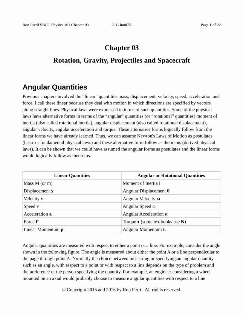
Ron Ferril SBCC Physics 101 Chapter 03 2017Jun07A Page 1 of 22 Chapter 03 Rotation, Gravity, Projectiles and Spacecraft Angular Quantities Previous chapters involved the “linear” quantities mass, displacement, velocity, speed, acceleration and force. I call these linear because they deal with motion in which directions are specified by vectors along straight lines. Physical laws were expressed in terms of such quantities. Some of the physical laws have alternative forms in terms of the “angular” quantities (or “rotational” quantities) moment of inertia (also called rotational inertia), angular displacement (also called rotational displacement), angular velocity, angular acceleration and torque. These alternative forms logically follow from the linear forms we have already learned. Thus, we can assume Newton's Laws of Motion as postulates (basic or fundamental physical laws) and these alternative form follow as theorems (derived physical laws). It can be shown that we could have assumed the angular forms as postulates and the linear forms would logically follow as theorems. Linear Quantities Angular or Rotational Quantities Mass M (or m) Moment of Inertia I Displacement x Angular Displacement θ Velocity v Angular Velocity ω Speed v Angular Speed ω Acceleration a Angular Acceleration α Force F Torque τ (some textbooks use N) Linear Momentum p Angular Momentum L Angular quantities are measured with respect to either a point or a line. For example, consider the angle shown in the following figure. The angle is measured about either the point A or a line perpendicular to the page through point A. Normally the choice between measuring or specifying an angular quantity such as an angle, with respect to a point or with respect to a line depends on the type of problem and the preference of the person specifying the quantity. For example, an engineer considering a wheel mounted on an axial would probably choose to measure angular quantities with respect to a line © Copyright 2015 and 2016 by Ron Ferril. All rights reserved.
Transcript of Chapter 03 Rotation, Gravity, Projectiles and Spacecraft
Ron Ferril SBCC Physics 101 Chapter 03 2017Jun07A Page 1 of 22
Chapter 03
Rotation, Gravity, Projectiles and Spacecraft
Angular QuantitiesPrevious chapters involved the “linear” quantities mass, displacement, velocity, speed, acceleration andforce. I call these linear because they deal with motion in which directions are specified by vectors along straight lines. Physical laws were expressed in terms of such quantities. Some of the physical laws have alternative forms in terms of the “angular” quantities (or “rotational” quantities) moment of inertia (also called rotational inertia), angular displacement (also called rotational displacement), angular velocity, angular acceleration and torque. These alternative forms logically follow from the linear forms we have already learned. Thus, we can assume Newton's Laws of Motion as postulates (basic or fundamental physical laws) and these alternative form follow as theorems (derived physical laws). It can be shown that we could have assumed the angular forms as postulates and the linear formswould logically follow as theorems.
Linear Quantities Angular or Rotational Quantities
Mass M (or m) Moment of Inertia I
Displacement x Angular Displacement θ
Velocity v Angular Velocity ω
Speed v Angular Speed ω
Acceleration a Angular Acceleration α
Force F Torque τ (some textbooks use N)
Linear Momentum p Angular Momentum L
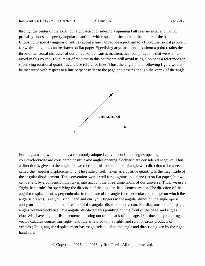
Angular quantities are measured with respect to either a point or a line. For example, consider the angleshown in the following figure. The angle is measured about either the point A or a line perpendicular to the page through point A. Normally the choice between measuring or specifying an angular quantity such as an angle, with respect to a point or with respect to a line depends on the type of problem and the preference of the person specifying the quantity. For example, an engineer considering a wheel mounted on an axial would probably choose to measure angular quantities with respect to a line
© Copyright 2015 and 2016 by Ron Ferril. All rights reserved.
Ron Ferril SBCC Physics 101 Chapter 03 2017Jun07A Page 2 of 22
through the center of the axial, but a physicist considering a spinning ball sees no axial and would probably choose to specify angular quantities with respect to the point at the center of the ball. Choosing to specify angular quantities about a line can reduce a problem to a two-dimensional problemfor which diagrams can be drawn on flat paper. Specifying angular quantities about a point retains the three-dimensional character of our universe, but causes mathematical complications that we wish to avoid in this course. Thus, most of the time in this course we will avoid using a point as a reference for specifying rotational quantities and use reference lines. Thus, the angle in the following figure would be measured with respect to a line perpendicular to the page and passing though the vertex of the angle.
For diagrams drawn in a plane, a commonly adopted convention is that angles opening counterclockwise are considered positive and angles opening clockwise are considered negative. Thus, a direction is given to the angle and we consider this combination of angle with direction to be a vector called the “angular displacement” θ. The angle θ itself, taken as a positive quantity, is the magnitude of the angular displacement. This convention works well for diagrams in a plane (as on flat paper) but we can benefit by a convention that takes into account the three dimensions of our universe. Thus, we use a“right-hand rule” for specifying the direction of the angular displacement vector. The direction of the angular displacement is perpendicular to the plane of the angle (perpendicular to the page on which the angle is drawn). Take your right hand and curl your fingers in the angular direction the angle opens, and your thumb points in the direction of the angular displacement vector. For diagrams on a flat page, angles counterclockwise have angular displacements pointing out the front of the page, and angles clockwise have angular displacements pointing out of the back of the page. (For those of you taking a vector calculus course, this right-hand rule is related to the right-hand rule for cross products of vectors.) Thus, angular displacement has magnitude equal to the angle and direction given by the right-hand rule.
© Copyright 2015 and 2016 by Ron Ferril. All rights reserved.

Ron Ferril SBCC Physics 101 Chapter 03 2017Jun07A Page 3 of 22
Angular KinematicsFor the linear quantities, the rate of change of the displacement vector x is the velocity vector v. For angular quantities, the rate of change of the angular displacement vector θ is the angular velocity ω. Consider a spinning wheel. The angular velocity, also called the rotational velocity, is perpendicular to the plane of (or flat sides of) the spinning wheel. If you curl the fingers of your right hand in the angular direction the wheel spins then your thumb gives the direction of the angular velocity vector. If the direction of the angular displacement vector changes direction during an interval of time, you can curl your fingers in the angular direction the vector's direction changed, and your thumb gives the direction of the average angular velocity resulting for that interval of time. For linear quantities, the rateat which a distance of travel x was accomplished is the speed v. For angular quantities, the rate at which an angle θ changes is the angular speed ω.
For linear quantities, the rate at which the velocity v changes is the acceleration a. For angular quantities, the rate at which the angular velocity ω changes is the angular acceleration α. If a spinning wheel is made to spin faster, the resulting angular acceleration vector points in the same direction as theangular velocity vector. If the spinning wheel is slowed, the angular acceleration vector points in the direction opposite the angular velocity vector. If the axis (or the axial) of the spinning wheel is turned during an interval of time while the wheel is spinning, then the angular velocity vector changes direction and we have an angular acceleration during that interval of time. Then the angular acceleration is perpendicular to the plane in which the angular velocity vector is rotating, and you can curl the fingers of your right hand in the direction the vector rotates so your thumb points in the direction of the angular acceleration vector.
Linear Kinematics Angular or Rotational Kinematics
Δx = vavg Δt Δθ = ωavg Δt
Δv = aavg Δt Δω = αavg Δt
y = ½ a t2 θ = ½ αavg t2
The angular quantities θ, θ, ω and α describe the kinematics of rotational motion. The preceding table shows the linear kinematic equations and their angular analogs.
© Copyright 2015 and 2016 by Ron Ferril. All rights reserved.

Ron Ferril SBCC Physics 101 Chapter 03 2017Jun07A Page 4 of 22
Linear Kinematic Quantities with Rotational MotionLinear kinematic quantities can be used to describe rotational motion. Consider a body moving in a circle of radius R and at constant speed (but not constant velocity). A common example (often used as ademonstration in classes) is a ball attached to a string and swung overhead. As the body moves in a circle at constant angular speed ω, it is accelerating because the direction of the velocity is changing. The force vector and the acceleration vector both point to the center of the circle. The acceleration vector, pointing at the center, is called the “centripetal acceleration” or “radial acceleration” aR. The (linear) velocity of the ball is tangential to the circle as shown in the following diagram. This velocity is called the “tangential velocity” vT of the ball. The direction of the tangential velocity continues to change as the ball moves in the circular path.
If the body continues to move in the circle but the speed of the body increases, there is a tangential acceleration aT in the direction of the tangential velocity. The total acceleration of the body is the sum or the tangential and radial accelerations.
a = aT + aR
The magnitude of the radial acceleration is
© Copyright 2015 and 2016 by Ron Ferril. All rights reserved.

Ron Ferril SBCC Physics 101 Chapter 03 2017Jun07A Page 5 of 22
aR = Rω2
Since the body continues to move in a circle, the magnitude of the tangential acceleration is the rate of change of the speed of the body.
Angular DynamicsThe force causing the radial acceleration is called the centripetal force FR and points toward the center of the circle. If the speed of the ball changes then the acceleration vector a is the vector sum of the radial acceleration (which points toward the center of the circle) and the “tangential acceleration” aT which is tangent to the circle.
a = aR + aT
The magnitudes of these vectors have the following relations in terms of the radius R of the circle and mass M of the moving body.
vT = R ω
aR = vT2 / R = R ω2
FR = M aR = M vT2 / R
Care must be taken with equations that have linear quantities like vT and angular quantities like ω. The units greatly matter. Engineers and scientists often prefer to use metric units for the linear quantities and measure angles in “radians” rather than in degrees or revolutions so calculations are easier. The “radian” is usually abbreviated “rad” in numerical expressions. Using units other than radians for angle causes some complications in results of calculations. Some people argue that a radian is not a true unit because it is defined as a ratio or an arc length to a linear length and the units cancel away in the ratio. Indeed, the radians often suddenly disappear in a calculation. For example, the magnitude of centripetalacceleration is aR = Rω2 and may have units of m/s2. However, the magnitude of angular velocity ω has units of angle per time such as, for example, radians per second. If radius R is expressed in meters, thenRω2 has units of rad2 m/s2 but these units are supposed to be m/s2 since this quantity is an acceleration. The radians rad2 merely vanish from the calculation. Thus, you can understand a reason why some people claim that the radian is not a true unit. There is a temptation to write the magnitude of angular velocity in units of inverse seconds (1/s) instead of radians per second (rad/s) but such an omission of radians would confuse some people. The safest way to view such problems is to consider a rad/s to be the same as 1/s, and a rad/s2 to be the same as 1/s2, so the equations for centripetal acceleration have no unit problems.
© Copyright 2015 and 2016 by Ron Ferril. All rights reserved.

Ron Ferril SBCC Physics 101 Chapter 03 2017Jun07A Page 6 of 22
The angular analog of force is a vector called “torque” τ. Like other angular quantities, torque is measured of specified with respect to either a point or a line, and we refer to the torque “about a point” or “about a line.” Force and torque are vectors, but the torque depends on both the force and the location where the force acts. Let r be the vector from the reference (line or point) to the point where the force acts, with this displacement vector perpendicular to the reference line if the reference is a line so the magnitude r is the distance from the reference line to the point where the force acts. The torque isthe following cross product.
τ = r X F
τ = |r F sin θ|
The right-hand rule is used to show the direction of the torque. You lay the fingers of your right hand along the direction of r and curl your fingers toward the direction of the force F so your thumb points in the direction of the torque τ. This is easy to understand when your instructor illustrates this in class, but is harder to understand from merely reading this paragraph. Thus, I should state the concept in more than one way.
Let me define torque again with slightly different words. Consider a reference line about which we can specify rotational quantities like angular displacement. Consider a force F that acts at a point at a known distance from the reference line. Let x be the displacement vector perpendicular to the referenceline with tail on the reference line and head at the point where the force acts. The torque τ due to this force is a vector defined as the cross product of the displacement x and the force F.
τ = x x F
Some people prefer using the following procedure to express the direction and magnitude of the torque.The following figure shows a force F acting at at a point which is away from the reference point or lineabout which we want to specify the torque.
© Copyright 2015 and 2016 by Ron Ferril. All rights reserved.

Ron Ferril SBCC Physics 101 Chapter 03 2017Jun07A Page 7 of 22
The direction of the torque vector is given by another right-hand rule. Draw the displacement vector from the point or line, about which the torque is specified, to the place where the force acts. If your reference is a line instead of a point, then draw this displacement vector perpendicular to the reference line. Next draw the displacement vector with its tail joined to the tail of the force vector. Curl your fingers from the direction of the displacement vector toward the direction of the force vector, then your thumb gives the direction of the torque vector (out of the page toward you). The following figure illustrates the displacement and force vectors. Notice the displacement vector was drawn twice, once ineach of two locations, to help show how your fingers would curl from displacement direction toward the force direction. The curved arrow in the figure shows the direction you would curl your fingers.
© Copyright 2015 and 2016 by Ron Ferril. All rights reserved.

Ron Ferril SBCC Physics 101 Chapter 03 2017Jun07A Page 8 of 22
Next, we the magnitude of the torque should be calculated. To do this, we need to learn about another trigonometric function. In Lecture Summary #2, a trigonometric function called the “cosine” was introduced. In order to discuss the magnitude of the torque, introducing another trigonometric function,the “sine” of an angle, is useful. The sine is abbreviated as “sin” in equations. Thus, the sine of an angleθ is written as sin θ. The following figure can be used to illustrate the relationship between the cosine and sine in terms of a right triangle. Notice the direction the angle opens is counterclockwise in the figure. The direction matters. The sine of an angle opening clockwise is the product of -1 and the sine of the angle opening counterclockwise.
© Copyright 2015 and 2016 by Ron Ferril. All rights reserved.

Ron Ferril SBCC Physics 101 Chapter 03 2017Jun07A Page 9 of 22
The “legs” of the right triangle are the short sides and the hypotenuse is the long side. Notice the angle θ marked in the figure. The cosine of this angle is the ratio of the length of the leg adjacent to the angle to the length of the hypotenuse. The sine of the angle is the ratio of the length of the leg opposite the angle to the length of the hypotenuse.
cos θ = x/H
sin θ = y/H
The magnitude τ of the torque is the product of three factors: the magnitude F of the force, the magnitude of the displacement, perpendicular to the reference line, from the reference line to the point at which the force acts and the sine of the angle between the force and displacement vector.
τ = F x sin θ
The value of the magnitude of torque is zero when the force and displacement vectors lie along the same line because the sine is zero.
sin 0 = 0
sin 180 degrees = 0
The for constant magnitudes of force and displacement, the torque is maximum when the force and displacement vectors are perpendicular.
sin 90 degrees = 1
© Copyright 2015 and 2016 by Ron Ferril. All rights reserved.

Ron Ferril SBCC Physics 101 Chapter 03 2017Jun07A Page 10 of 22
sin 270 degres = 1
Thus, the torque vector τ has direction given by the right-hand rule and magnitude given by the productof the magnitude of force, the magnitude of the displacement from reference to point where the force acts and the sine of the angle between the force and displacement. (You may notice that the inclusion ofthe sine of the angle assures us that the torque describes a “twisting” influence in that a nonzero torque indicates a force tends to twist about the reference point or line. For example, a wrench applies a force and a torque to twist a nut, bolt or screw.)
As torque is the angular analog of force, moment of inertia, I, is the angular analog of mass. Like the other angular quantities, moment of inertia is specified with respect to a point or line. For the simple case of a small mass M at a distance r from the point or line, the moment of inertia I is defined to be
I = Mr2
Notice the requirement that the body is small or “point-like” is important because this equation fails to hold true if the body is not tiny.
Suppose we want to calculate the moment of inertia (also called rotational inertia) I for the combinationof several small bodies of masses M1, M2, M3... and distances r1, r2, r3..., respectively, from the reference. It is important that we use the same reference line (or point) to specify the moments of inertia or else the following formula for the moment of inertia I does not work.
I = M1r12 + M2r2
2 + M3r32 + ….
Thus, the total moment of inertia for the combination of all those bodies is merely the sum of the moments of inertia for all the individual small bodies.
Writing the moment of inertia for a body can be complicated if the body has a complicated shape, but the branch of mathematics called “calculus” allows extending the definition of moment of inertia for the simple case of a small body of mass M at distance r (or several tiny point-like bodies with distancesmeasured from the same reference) to any shape of body or closed system. Searches of the Internet yield lists the results for several shapes. For the formulas listed to work, the bodies are assumed to be “homogeneous” which means all parts of the bodies have the same composition or same density. Noticethe value of I depends on the choice of reference axis. The listings indicate the choice of axis in each case.
© Copyright 2015 and 2016 by Ron Ferril. All rights reserved.

Ron Ferril SBCC Physics 101 Chapter 03 2017Jun07A Page 11 of 22
When a moment of inertia is calculated with respect to a line, the moment of inertia is a scalar. Earlier Isaid that angular quantities can be taken with respect to a line or a point. There is a complication when the moment of inertia is taken wither respect a point. Technically, the moment of inertia is neither a vector nor a scalar when it is specified with respect to a point, but becomes a matrix or a quantity calleda “tensor” which is like a matrix but with additional properties. The subject of tensors is beyond this course in conceptual physics.
The angular momentum L can be defined several ways. One easy way is to say it is
L = I ω
The angular form of Newton's Second Law of Motion is
τ = K ΔL/Δt
where the constant K depends on the units we choose to use. For metric units, K=1 and K disappears from the equation.
K ΔL = τ Δt
For constant moment of inertia,
τ = I α (for constant I)
As there is a Law of Conservation of Linear Momentum, there is also a Law of Conservation of Angular Momentum.
Law of Conservation of Angular Momentum. If the net torque τnet on a closed system is zero, then the total angular momentum of the system is conserved.
Thus, the total angular momentum of a closed and isolated system remains constant. Changes in total angular momentum require external torques acting on the system. The angular momentum is the product of the moment of inertia and the angular velocity. If the moment of inertia I of a body changes while it is freely spinning body (that is, a body on which the net torque is zero), then the angular velocity changes to maintain the angular momentum constant. This is how an ice skater changes his or her angular velocity when either extending or retracting arms and legs.
Linear Dynamics Angular or Rotational Dynamics
Fnet = K Δp / Δt τ = K' ΔL/Δt
© Copyright 2015 and 2016 by Ron Ferril. All rights reserved.

Ron Ferril SBCC Physics 101 Chapter 03 2017Jun07A Page 12 of 22
Linear Dynamics Angular or Rotational Dynamics
Fnet = K M a (for constant M) τ = K' I α (for constant I)
K Δp = Fnet Δt K' ΔL = τ Δt
M I
p = mv L = I ω
K = ½ m v2 K = ½ I ω2
Newton’s Third Law and RotationSince there is a rotational version of Newton’s Second Law of Motion, people may wonder if there is a rotational version of Newton’s Third Law of Motion. There is, but some people consider it useless because it requires careful selection of a single reference line (or point) for writing torques. The linear form is
F12 = −F21
and the rotational version is
τ12 = −τ21
For this equation to hold, the reference line (or point) must be the same for specifying both torques. This is the problem some mechanical engineers see with the equation. When an engineer wants to writeequations for gears meshed together, it is convenient to specify different reference lines for different gears, but then the equation τ12 = −τ21 fails to hold true and the engineer has trouble using it to specify how the torque one gear applies to a second gear relates to the “reaction” torque the second gear appliesto the first gear. Thus, engineers often discard the rotational version of the Third Law and ignore its existence.
Inertial ForcesSome scientists and engineers like to rearrange the equations of Newton's Second Law so the right sides are zero and they can work with inertial forces. If the inertial forces are included in the vector sum of forces, then the vector sum is zero. For linear momentum p,
Fnet = K Δp / Δt
© Copyright 2015 and 2016 by Ron Ferril. All rights reserved.

Ron Ferril SBCC Physics 101 Chapter 03 2017Jun07A Page 13 of 22
Fnet - K Δp / Δt = 0
- K Δp / Δt = inertial force
Fnet = ma
Fnet - ma = 0
ma = inertial force
These inertial forces are sometimes called “fictitious forces” but feel very real to passengers inside a car when the car accelerates or goes in a curved path. When a car accelerates forward, the passengers feel an inertial force pulling them back into their seats. The “centrifugal force” is an inertial force. It has the same magnitude as but opposite direction to the centripetal force. The centrifugal force FC is thefictitious “force” that passengers feel pressing them to the outside of curves.
FC = - FR = - M aR
FC = FR = M aR = M vT2 / R = M R ω2
Mass and GravityThe “center of mass” of a body or a system is the average position of the mass. The “center of gravity” of a body is the average position of weight. On Earth, the weight of a body is proportional to its mass.
weight = Mg
Thus, on Earth, the center of mass of a body is also the center of gravity. One way to find the center of gravity of a body is to hang the body by different parts. For each part by which you hang the body, mark the vertical line passing through the part by which the body hangs. The intersection of these lines is the center of gravity. This works for a uniform gravitational field. When an object sits and is supported on its own base or feet, if the center of gravity is not over such supports then a torque will cause the object to fall over.
When forces are applied to a body or system, the body or system may move and spin. Thus, different parts have different accelerations. The linear forms of Newton's Second Law directly apply to the acceleration or rate of change of total momentum of the center of mass of a body or system. The angular forms of Newton's Second Law directly apply to the rotation of the body or system with respectto a point or line. The combination of linear and angular forms allows complete specification of the dynamics of a body or system.
© Copyright 2015 and 2016 by Ron Ferril. All rights reserved.

Ron Ferril SBCC Physics 101 Chapter 03 2017Jun07A Page 14 of 22
In addition to the laws of motion, Newton also stated a law of gravity. He stated that every object with nonzero mass attracts any other object with a force he (and others) called gravity or the gravitational force. Consider the special case of two bodies that are either very small or uniform spheres. Call one body the first body with mass M1 and the other the second body with mass M2. It is important to specifythat the bodies are apart from each other so one body is not inside the other. Newton's Law of Gravity states that the gravitational force FG of the first body on the second body is directed toward the center of the first body and has magnitude proportional to the product of the masses of the two bodies and inversely proportional to the square of the distance between their centers. We can write the magnitude FG as
FG= G M1 M2 / r2
where G is the “universal gravitational constant.” Experiments were done to determine the value of G. Our textbook gives the value for use with the metric system of units.
Newton's Law of Gravity: Any two bodies, apart from each other, that either are very small or are uniform spherical balls, with the first body having mass M1 and the second body having mass M2, separated by a distance r between their centers, attract each other so that the force FG the first body exerts on the second body is directed toward the center of the first body and has magnitude FG= G M1 M2 / r2 where G is a constant that depends on the units chosen.
You may at first regret that this law holds only for tiny objects or uniform spheres (spheres with uniform composition or density). This is not a problem for scientists and engineers because the branch of mathematics (which Newton invented) called “calculus” allows the law to be extended to bodies of any shape and composition. The resulting equation of such an extension is often not as simple as the equation given in Newton's Law of Gravity.
Newton did not give a physical cause for the gravitational force. His law of gravity was a postulate or afundamental physical law. This law has been tested in many ways over centuries. No good physical explanation for why there is a gravitational force was given, even though people asked for a physical reason, until the early 20th century. Einstein formed his own theory of gravity called the General Theoryof Relativity. In this theory, Einstein stated that the gravitational force can be considered to be caused by “curvature” of a four-dimensional space called “spacetime.” Thus, for a moment, physicists can celebrate their new explanation of the physical reason for the gravitational force, but then somebody is likely to ask why there is curvature. Oh well! Back to research!
© Copyright 2015 and 2016 by Ron Ferril. All rights reserved.

Ron Ferril SBCC Physics 101 Chapter 03 2017Jun07A Page 15 of 22
More on GravityThe “center of mass” of a body or a system is the average position of the mass. The “center of gravity” of a body is the average position of weight. On Earth, the weight of a body is proportional to its mass.
weight = Mg
Thus, on Earth, the center of mass of a body is also the center of gravity. One way to find the center of gravity of a body is to hang the body by different parts. For each part by which you hang the body, mark the vertical line passing through the part by which the body hangs. The intersection of these lines is the center of gravity. This works for a uniform gravitational field. When an object sits and is supported on its own base or feet, if the center of gravity is not over such supports then a torque will cause the object to fall over.
When forces are applied to a body or system, the body or system may move and spin. Thus, different parts have different accelerations. The linear forms of Newton's Second Law directly apply to the acceleration or rate of change of total momentum of the center of mass of a body or system. The angular forms of Newton's Second Law directly apply to the rotation of the body or system with respectto a point or line. The combination of linear and angular forms allows complete specification of the dynamics of a body or system.
Gravitational Fields of Earth, Moon and SunThe gravitational fields of the Earth, Moon and Sun are not uniform (that is, not the same at all locations). We detect this lack of uniformity only when we consider large distances or do very sensitivemeasurements. The value of acceleration due to gravity g varies for various locations on the Earth's surface, but these variations are small. The magnitude of this acceleration decreases as we rise in altitude above the Earth, but we don't notice this change unless we rise fairly far above the Earth. Thus, the mg uniform approximation is fairly good on the surface of the Earth.
When we look at larger-scale phenomena, we notice some of the effects of the lack of uniformity. The Earth's ocean tides are caused by this lack of uniformity. The gravitational force of the Moon on the oceans of Earth is strongest on the side of Earth toward the Moon and weakest on the side opposite the Moon. The difference in forces on different sides causes the fluid ball of ocean water to be stretched so that water rises about one meter above the average level on the sides near to and far from the Moon. Onthe sides adjacent to those where water rises, the ocean water drops to about one meter below the
© Copyright 2015 and 2016 by Ron Ferril. All rights reserved.

Ron Ferril SBCC Physics 101 Chapter 03 2017Jun07A Page 16 of 22
average water level. Thus, we have high and low tides. The Sun also produces a similar effect, but the Sun is so far from Earth that the difference in its gravitational pull on two sides of Earth is smaller than the difference produced by the Moon.
We can use Newton's laws to see why all objects fall with the same acceleration g in vacuum (near the surface of the Earth). The force of gravity FG on a body of mass m can be expressed by Newton's Second Law of Motion and Newton's Law of Gravity. Let M be the mass of the Earth and notice the distance r from the center of the Earth is the radius of the Earth.
FG = ma = mg
FG = G M m / r2
Thus,
a = g = G M / r2
Notice that the mass m of the body does not appear in this expression for acceleration. This independence from mass m can introduce the concept of gravitational field.
The expression GM/r2 is called the magnitude of the “gravitational field” at distance r from the center of a body with mass M.
Magnitude of the gravitational field = G M / r2
The “gravitational field” is a vector with the same direction as the gravitational force. The direction of the gravitational field of a uniform spherical body is toward the center of the body. The gravitational force is a property of two bodies. The gravitational field is a property of just one body because it depends only on the mass M and the distance r, but is independent of the mass m of a body experiencing the gravitational field. The field is a vector field with the field vector pointing toward the center of the body. In the case where the body is the Earth and the distance from the center is the radiusof the Earth, the gravitational field is the acceleration due to gravity g.
Inside a Spherical BodyNewton's Law of Gravity directly applies to uniform spherical bodies and tiny masses called “point masses”. However, the implicit assumption has been that the law is applied to locations outside of the bodies. When you enter a uniform spherical body, there are complications and the branch of mathematics called “calculus” is used with Newton's Law of Gravity to determine the gravitational
© Copyright 2015 and 2016 by Ron Ferril. All rights reserved.

Ron Ferril SBCC Physics 101 Chapter 03 2017Jun07A Page 17 of 22
forces at locations inside the body. We don't use calculus in this course but we can still use results of itsuse. Here we describe an important result.
Consider the situation inside a uniform spherical shell. At a point inside the shell, the gravitational fielddue to the shell is zero. As an example, consider the Earth to be a uniform spherical body. (The Earth is close to being such a body but it is not really uniform and not perfectly spherical.) If we were to dig a tunnel to the center of the Earth, the Earth's gravitational force would diminish as we descended towardthe center of the Earth and would have zero magnitude at the center. If you found a planet that was a uniform spherical shell and went inside, we would find the gravitational force of the planet was zero inside.
If you dig a tunnel into a planet like the Earth with mass M and radius R, and you dig the tunnel deep enough that you descend till are at a distance r from the center of the planet, then the magnitude of the gravitational force on you (that is, your weight) is a fraction of what it was when you were on the surface. The gravitational force continues to decrease as you dig deeper toward the center of the Earth, and becomes zero at the center.
Independence of Horizontal and Vertical MotionsThe vector nature of quantities in the equations of kinetics and dynamics assures us that the horizontal and vertical motions of bodies in Earth's gravitation field are independent. The vertical motion of a body is the same whether it is thrown upwards to reach a certain height H and falls back, or it is fired from a gun so that it travels horizontally but rises to the same height H and then comes back down (but still with a horizontal component of velocity).
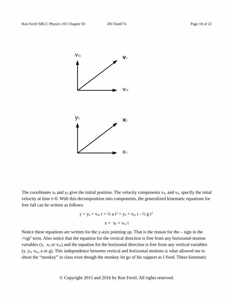
A projectile thrown with an initial velocity v0 from a position x0 is in free fall even though it has an initial velocity. However, we need to change the free-fall equations must be changed to include this initial velocity and the position (away from zero height). Since the vertical and horizontal motions are to be independent, we should separate the vectors v0 and x0 into vertical and horizontal components v0x,v0y, x0 and y0 as shown in the following diagram.
© Copyright 2015 and 2016 by Ron Ferril. All rights reserved.
Ron Ferril SBCC Physics 101 Chapter 03 2017Jun07A Page 18 of 22
The coordinates x0 and y0 give the initial position. The velocity components v0x and v0y specify the intialvelocity at time t=0. With this decomposition into components, the generalized kinematic equations for free fall can be written as follows.
y = y0 + v0y t + ½ a t2 = y0 + v0y t - ½ g t2
x = x0 + v0x t
Notice these equations are written for the y-axis pointing up. That is the reason for the – sign in the -½gt2 term. Also notice that the equation for the vertical direction is free from any horizontal-motion variables (x, x0 or v0x) and the equation for the horizontal direction is free from any vertical variables (y, y0, v0y, a or g). This independence between vertical and horizontal motions is what allowed me to shoot the “monkey” in class even though the monkey let go of his support as I fired. These kinematic
© Copyright 2015 and 2016 by Ron Ferril. All rights reserved.

Ron Ferril SBCC Physics 101 Chapter 03 2017Jun07A Page 19 of 22
equations tell the height y and the horizontal position x at any time t during the projectile (free-fall) motion.
Orbits and Escape VelocityA satellite in a circular orbit about the Earth must have tangential velocity with magnitude vT such that
vT2/R = GM/R2
vT = √[GM/R]
where M is the mass of the Earth and R is the radius of the orbit. (The symbol “√” indicates the square root. Many people are used to seeing that symbol including a bar over the top of the quantity being square rooted.) A satellite in elliptical orbit obeys the Law of Conservation of Energy. Thus, a decrease in potential energy must be accompanied by a rise in kinetic energy.
When a spacecraft leaves the Earth, it can do so by getting up to “escape velocity” which is a velocity great enough in magnitude vE that gravity will not pull the spacecraft back to Earth. Consider a spacecraft launched directly upward from the Earth. The potential energy change associated with separating the spacecraft of mass m from the Earth (sending the spacecraft to infinity meters from the Earth) is 2GMm/R where M is the mass of Earth and r is the distance from the center of the Earth at which the spacecraft is to achieve escape velocity. To achieve such a change in potential energy, the kinetic energy must be as large as the change in potential energy. The magnitude vE of the escape velocity obeys
½ m vE2 = GMm/r
vE = √[2GM/r]
This formula looks like the formula for the magnitude of the tangential velocity of a satellite in circular orbit, but has a factor of 2 inside the square root. .
© Copyright 2015 and 2016 by Ron Ferril. All rights reserved.

Ron Ferril SBCC Physics 101 Chapter 03 2017Jun07A Page 20 of 22
Angular Quantities and Rotational Dynamics Summary
Linear Quantities Angular or Rotational Quantities
Mass M Moment of Inertia I
Displacement x Angular Displacement θ
Velocity v Angular Velocity ω
Speed v Angular Speed ω
Acceleration a Angular Acceleration α
Force F Torque τ (some textbooks use N)
Linear Momentum p Angular Momentum L
Linear Kinematics Angular or Rotational Kinematics
Δx = vavg Δt Δθ = ωavg Δt
Δv = aavg Δt Δω = αavg Δt
Δx = v0t + ½ a t2 (for constant acceleration a) Δθ = ω0t + ½ α t2 (for constant α)
Linear Dynamics Angular or Rotational Dynamics
Fnet = K Δp / Δt τ = K' ΔL/Δt
Fnet = K M a (for constant M) τ = K' I α (for constant I)
K Δp = Fnet Δt K' ΔL = τ Δt
M I
p = mv L = I ω
Tangential velocity vT: magnitude Rω direction forward tangent to circle or arc. Centripetal acceleration aR: magnitude aR = Rω2 = vT
2/R direction toward center of circle or arc. Centripetal force FR = m aR and has magnitude FR = m Rω2 = m vT
2/R and direction toward the center. Centrifugal force is an inertial force with same magnitude as centripetal force but has direction opposite the direction of the centripetal force.
© Copyright 2015 and 2016 by Ron Ferril. All rights reserved.

Ron Ferril SBCC Physics 101 Chapter 03 2017Jun07A Page 21 of 22
Example CalculationsMost of the calculations with angular quantities correspond to similar calculations with linear quantities. The angular units such as radians can cause complications.
Example 01. A circular wheel with a radius of r = 1 meter turns on an axis through its center and perpendicular to the plane of the wheel. The wheel turns with a constant angular velocity of 10 radians per second. Consider a point on the outer rim (edge) of the wheel. The magnitude of the centripetal acceleration aR of that point is
aR = Rω2 = 1 m x (10 rad/s)2 = 100 rad2 m/s2 = 100 m/s2
and the direction of the centripetal acceleration is toward the center of the circular wheel. Notice how the radians conveniently disappeared in the calculation. We consider rad2 m/s2 = m/s2.
Example 02. Suppose a wheel is mounted on an axial and spins with constant angular velocity about this axial so that it turns 2 radians in 2 seconds. We view the wheel by looking down the axial and see the wheel is turning clockwise. We calculate the magnitude ω of the angular velocity ω
ω = Δθ / Δt = 2 rad / [2 s] =1 rad/s
We then use the right-hand rule to see that the direction of the angular momentum vector ω is down theaxial away from us. Suppose we want to know the angular displacement the wheel will turn in 7 seconds. We have already found the angular velocity to be 1 rad/s along the axial in the direction away from us. Thus,
Δθ = ω Δt = 1 rad/s x 7 s along the axial and away from us = 7 rad along the axial and away from us
Notice I kept the magnitude (7 rad) and direction (along the axial and away from us) together in specifying the vector quantity. Some people prefer to handle the magnitude and direction separately, and some people like to handle them together. However, correct specification of a vector requires both magnitude and direction.
Example 03. Consider a tiny bug on the rim of a spinning wheel at the moment when the bug is at the top of the wheel. Suppose the wheel is mounted on an axial running North and South, the radius of the wheel is R = 1 m and the wheel is spinning with an angular velocity ω = 2 rad/s toward the North. The magnitude vT of the tangential velocity vT is
© Copyright 2015 and 2016 by Ron Ferril. All rights reserved.
Ron Ferril SBCC Physics 101 Chapter 03 2017Jun07A Page 22 of 22
vT = R ω = 1 m x 2 rad/s = 2 m rad/s = 2 m/s
Notice the radians suddenly disappear from the expression. To find the direction of the tangential velocity vT, consider viewing the spinning wheel from the South looking North. You can use the right-hand rule to see that, from this viewpoint, we would see the wheel spinning clockwise. Thus, the bug on top of the wheel would be moving toward the East. Thus, the tangential velocity is
vT = 2 m/s East
Example 04. Suppose an ice skater first spins with an angular velocity ω = 2 rad/s upward. You can use the right-hand rule to show that the skater, as viewed from above, would be spinning counterclockwise. Suppose the moment of inertia I of the skater suddenly becomes half of what it was. (Ice skaters do this by suddenly pulling in their arms and legs to make themselves effectively thin.) We know the angular momentum is the product of the moment of inertia I and the angular velocity ω. We also know the angular momentum is conserved. Thus, if the moment of inertia is reduced to half its original value and no external torques are applied to the skater, the magnitude of the angular velocity must double to maintain the angular momentum constant. Thus the angular velocity becomes
ω = 2 x 2 rad/s upward = 4 rad/s upward
© Copyright 2015 and 2016 by Ron Ferril. All rights reserved.