Chap 2 - Section 2 - Upper Wing - Direct Drive · PDF fileWing spar and skin assembly. ... y...
17
Page 1 Chapter 2 Section 2 Upper Wing The top wing is constructed very similarly to the lower wing. Since you have the experience from building the lower wing, the instructions here will be abbreviated. Only the differences will be given in detail. You can refer to the lower wing instructions for any basic construction information. The upper wing will be constructed upside down. Materials: 16 - 3/32” x 4” x 48” balsa sheets 2 - 10-32 blind nuts 4 - 4-40 blind nuts 6 to 7 - 1/8” carbon rods 4 - Wing strut mounting posts Parts: Aileron servo extensions: 48” - 2 36” - 2
Transcript of Chap 2 - Section 2 - Upper Wing - Direct Drive · PDF fileWing spar and skin assembly. ... y...

Page 1
Chapter 2 Section 2 Upper Wing The top wing is constructed very similarly to the lower wing. Since you have the experience from building the lower wing, the instructions here will be abbreviated. Only the differences will be given in detail. You can refer to the lower wing instructions for any basic construction information. The upper wing will be constructed upside down. Materials: 16 - 3/32” x 4” x 48” balsa sheets 2 - 10-32 blind nuts 4 - 4-40 blind nuts 6 to 7 - 1/8” carbon rods 4 - Wing strut mounting posts Parts: Aileron servo extensions: 48” - 2 36” - 2

Page 2

Page 3
Recheck your building table for straightness.
Install a 10-32 blind nut in each top wing mount. Secure the nuts in place with
a square of glass cloth and thin CA. Run a tap through the nuts to clear the threads.
Glue the two mounts between the R1 ribs with thick CA. Be sure the sides with
the blind nuts are installed opposite the side of the ribs having the notches. Keep the rib edges flat on the table while gluing, so they will be perfectly aligned with one another.
Reinforce the mounts with balsa gusset stock on both sides. Sand the gussets to
match the contour of the ribs. Glue the mount reinforcements between the R1 ribs within the notches provided
for them.

Page 4

Page 5

Page 6
Fabricate two strut mounts as you did for the lower wing.

Page 7
Gusset the blocks using ½” balsa gusset stock and thick CA.
Glue the spar halves together to form an upper and lower set. Extend the
Grooves through the center of the joined spar halves. Glue the two ½” square balsa splice joiners to the center of each of the two
spars. Join the 3/32” balsa sheets to form the leading edge sheeting. Sand the sheeting
joints smooth. Trim the Leading edge sheeting to match the plan, making sure the edges are
perfectly straight.

Page 8
Join the leading edge sheeting to the front of the spars using thin CA.
With the spar assembly still held flat against the table, insert the 1/8” x 48”
round carbon rods into the spar grooves. Press the rods all the way to the bottom of the groove for its full length and apply thin CA.
Repeat with 1/8” x 24” carbon rods.
For the 212cc model, repeat one final time with 1/8” x 12” carbon rods.
Apply ample thin CA to the rods, clean any excess glue from the top of the
grooves and use kicker to cure the glue.
Page 9
Carbon rods installed in spar grooves - note overlap at center.
Fashion two aft wing skins to match the pattern using 3/32” x 4” x 48” balsa
sheeting. Note that this pattern is slightly different than the lower wing pattern. Sand the seems smooth.

Page 10
Glue one of the skins to one of the spar assemblies. Trim the spar ends to be
even with the skin. Pin the spar assembly to the work table. This is the top skin, but the wing is
constructed upside down.

Page 11
Wing spar and skin assembly. Mark the rib locations on your skin assembly, measuring from the outer tips of
the spar to the outside of each rib. Repeat the marks on the trailing edge of the aft wing skin.
Page 12
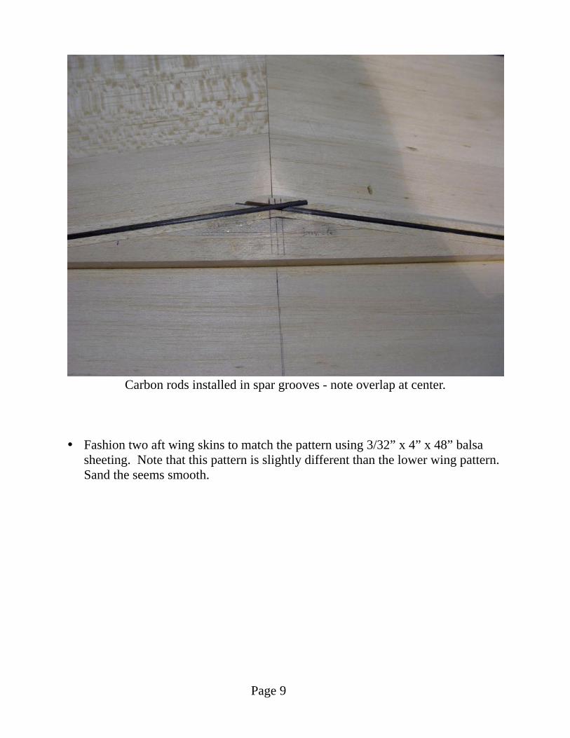
Position the R1 mount assembly into place on the center of the wing skin. The
mount reinforcements go up, since the wing is constructed upside down. Check alignment from both wing tips. When certain it is perfectly centered and perpendicular, tack the ribs in place on the spar with thin CA. Lift the aft skin so it is flush to the ribs and glue with thin CA.
Tack the ribs in place along the spar at the positions you marked, using a square
to ensure they are vertical. Glue them to the wing skin aft of the spar with thin CA.
Slide the wing trailing edge jig under the wing skin so the trailing edge of the
ribs are even with the forward edge of the jig. The inside edge of the jig goes under the R2 rib, but no farther towards the center of the wing. Pin in place.

Page 13
Using a straight edge to position jig under the wing skin. Slide the center jig so the aft edge is even with the trailing edge of the center
ribs. Pin in place. Shape and install the 3/8” square balsa leading edge spar in place. Sand the
inside ends to mate together. Sand the top and bottom edges so they match the size of the rib notches.
Lift and glue the leading edge sheeting to the ribs using thin CA. You will have
to trim the sheeting where they meet at center. Add a 3/32” balsa sheet splice inside the wing where the leading edge sheets
meet. Trim the sheeting that protrudes above the leading edge.

Page 14
Fit and glue the shear webs on top of the spar and between the ribs using thick CA. The webbing must be centered on the spar so it fully covers the carbon rod grooves.
Assemble the servo boxes with thin CA.
Mark the box locations on the wing skin.
Page 15
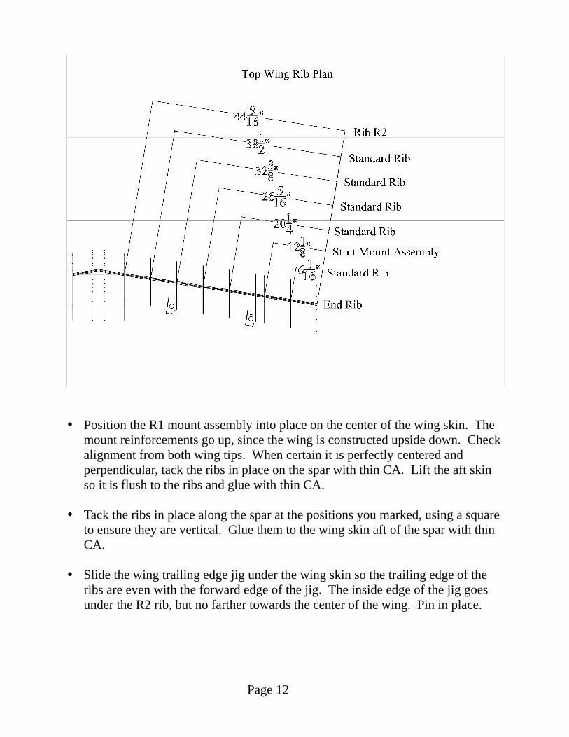
Sand the wing skin under the servo box locations to a 5 degree angle so the skin
will lay flat against the ribs when the boxes are installed. Glue the boxes in place.
Fit and install the 3/8” balsa trailing edge between the servo boxes.

Page 16
Use the trailing edge stock to fashion two aft spars in the center section of the
wing. Now is the time to install the servo wiring to the mounts. The wires will exit
through the rectangular holes in the front of the aft wing mount reinforcement. Trial fit the upper spar in place, making sure it fits flush on top of the shear
webs and ribs. When happy with the fit, remove the spar again. Remove all pins that will be covered by the leading edge sheeting. Use weights
to maintain the lower spar flat against the table. Glue the upper spar in place. Use slow CA so you have time to apply glue to
the ribs and webs before setting it in place. Use ample weight on the spar to ensure the wing will remain straight. Only glue the leading edge sheeting from the spar to about half way to the leading edge.

Page 17
Fit the second aft wing skin. Mark and sand bevels into the skin where the
servo boxes contact it. Trim and sand the lower wing skin in the center area, where it comes to a sharp edge. Bevel with sandpaper so the upper skin will lay over the top of the trailing edge in this area.
When satisfied with the fit, remove any remaining pins and glue the aft skin in
place using slow CA. Apply an even weight load to the skin while it dries. Remove the wing from the table and turn it over.
Hold the wing flat against the table using weights as required.
Working from the center of the wing out, bond the leading edge sheeting to the
ribs using thin CA. Go back to the center of the wing and working on about 6 inches at a time,
gently pull the sheeting flush against the leading edge spar and bond with thin CA.
Remove the weights from the wing. It is now structurally complete.
Trim the leading edge sheeting that extends beyond the front of the wing.
Sand the wing to shape.
Locate the wing mount reinforcement holes using a pin. Cut the holes out using
a sharp knife. Cutout the strut mount holes and install the 3/8” aluminum strut mounting
posts. Screw them in until the last thread is even with the surface of the wing.