Channel coding - HH
38
Channel coding
Transcript of Channel coding - HH

Channel coding

AWGN
Distribution
of received
’0’
Distribution
of received
’1’
The area corresponds
to the probability that
a ’1’ is interpreted as
a ’0’
The area corresponds
to the probability that
a ’0’ is interpreted as
a ’1’’1’
’0’
Decision boarder
Signal strength, S
transmitter receiver+m(t)si(t)
n(t)
( )m t%r(t)
0
bE B S
N R N=

Fading

Fading
X
Y

Interference
• Co-channel interference
• Adjacent channel interference

Channel coding
modulatorchannel coder
demodulatorchannel decoder
channel

Channel coding
Error detection
Error correctionError repeat reQuest
Block codes Block codes Convolution codes

Channel coding
Pe : bit error probability, or more commonly bit error rate (BER).
P1: The probability that a transmitted frame contains no error.
P2: Probability that, with an error detection algorithm in use, a
transmitted frame arrives with one or more undetected errors.
P3: Probability that, with an error detection algorithm in use, a
frame arrives with one or more detected bit errors but no
undetected bit errors.
P1=(1 - Pe)k
P2=1 - P1
Received Frame
P1 P2
P3

Channel coding
• The probability that a frame arrives with no bit
errors decreases when the probability of a
single bit error increases.
• The probability that a frame arrives with no bit
error decreases with increasing frame length.

Example (in the book)Consider that the BER on a 64 kpbs channel should be less than 10-6
Suppose now that we have the requirement that on average one frame with
undetected bit error should occur per day on a continuously used 64 kpbs
channel.
A frame length of 1000 bits is assumed. The total amount of frames
transmitted on one day is then:
(64000*3600*24)/1000 = 5.529*106
The maximum frame error rate then becomes:
1/(5.529*106 ) = 0.18*10-6
The actual frame error rate is however:
P1 = (0.999999)1000 = 0.999
which is about three orders of magnitude too large to meet our requirements.
Channel coding
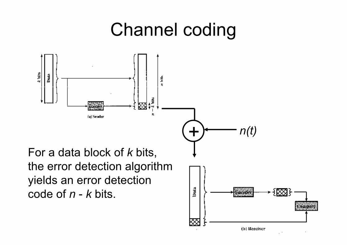
+ n(t)
For a data block of k bits,
the error detection algorithm
yields an error detection
code of n - k bits.

Parity check
• The parity check appends a parity bit to the
end of a block of data.
• A typical example is character transmission, in
which a parity is attached to each 7-bit
character.
• The value of this bit is selected so that the
character has an even number of 1s (even
parity) or an odd number of 1s (odd parity).

Error detection

Parity check (odd parity)
1110001
1
=> 11100011
1110000
0
11100000=>
The receiver examines the received characters and, if the total
numbers of 1s is odd it assumes that no error has occurred.
If one or any odd numbers of bits are inverted during the
transmission, then the receiver will detect an error, e.g. 11000011,
11000000.
However, if two (or any even number) of bits are inverted an
undetected error occurs.

Parity check (even parity)
1110001
0
=> 11100010
1110000
1
11100001=>
The receiver examines the received characters and, if the total
numbers of 1s is even it assumes that no error has occurred.
If one or any odd numbers of bits are inverted during the
transmission, then the receiver will detect an error, e.g. 11000010,
11000001.
However, if two (or any even number) of bits are inverted an
undetected error occurs.

Cyclic redundancy check (CRC)
• The most common error detecting codes is the cyclic redundancy check (CRC).
• Given a k bit block of bits, the transmitter generates an (n - k) bit sequence, known as the frame check sequence (FCS).
• The resulting frame consists of n bits, that is exactly devisable by some predetermined number.
• The receiver then divides the incoming frame by that number and, if there is no remainder, it assumes that there was no error.

CRC
Three different way to present the same thing:
•Modulo 2 arithmetic
•Polynomials
•Digital logic
Definitions:
T = n bit frame to be transmitted.
D = k bit block of data, the first k bits of T.
F = n - k bit FCS, the last n – k bits of T.
P pattern of n - k bits, predetermined divisor.
D F
k n-k
T, n bits

Modulo 2 arithmetic
1111
+ 1010
0101
1111
- 0101
1010
11001
� 11
11001
11001
101011
In coding theory many mathematical operations is performed in finite
number systems with certain algebraic constructions.
A simple but often used arithmetic is binary arithmetic:
Observe that in binary arithmetic is ‘1’ both positive and negative, this means
that 1+1 and 1-1 the same and that 1*1=1. For addition modulo 2 the symbol
� is used.
0 1
1 0
+ 0 1
0
1
* 0 1
0
1
0 0
0 1
Example:

CRC – Modulo 2 arithmetic
D F
k n-k
T, n bits
We would like T/P to
have no remainder,
where P is the
predefined pattern.
T = 2n-k D + F
By multiplying D by 2n-k, D is shifted to the left by n – k and
padded with zeros. Adding F, concatenates D and F, which is T.
Mathematical description:

CRC – Modulo 2 arithmetic
T should be exactly devisable by P, lets start with:
2n kD RQ
P P
−
= +
There is a quotient, Q, and a remainder, R. Because division is
modulo 2, the remainder will always be at least one bit shorter
than the divisor. The remainder is used as FCS, then:
2n kT D R−= +
This remainder, R, must satisfy our condition that the T/P has no
remainder:2 2n k n kT D R D R
P P P P
− −+
= = +
CRC – Modulo 2 arithmetic
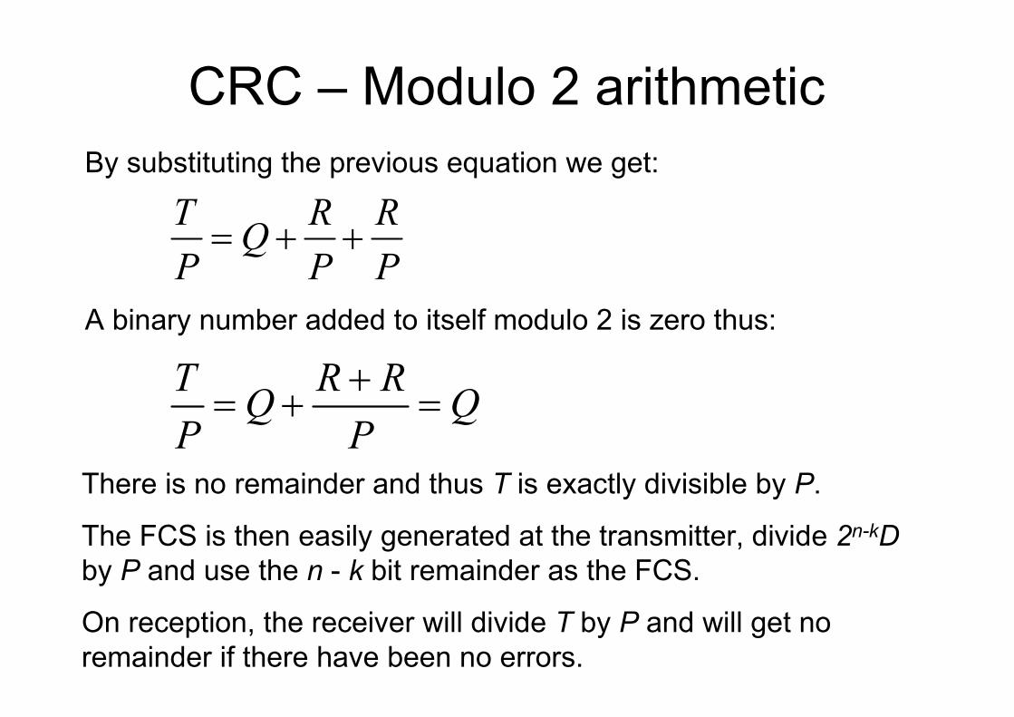
By substituting the previous equation we get:
T R RQ
P P P= + +
A binary number added to itself modulo 2 is zero thus:
T R RQ Q
P P
+= + =
There is no remainder and thus T is exactly divisible by P.
The FCS is then easily generated at the transmitter, divide 2n-kD
by P and use the n - k bit remainder as the FCS.
On reception, the receiver will divide T by P and will get no
remainder if there have been no errors.

CRC – Example (page 208)
Given:
Message, D = 1010001101 (10 bits)
Pattern, P = 110101 (6 bits)
FCS, R = to be calculated
Thus, n = 15 and k = 10 and n – k = 5
=>D is multiplied with 2n-k, shifted 5 steps to
the left, equal to: 101000110100000


CRC – ExampleIf there are no errors, the receiver receives T intact. The received
frame is then divided by P.


CRCThe pattern, P, is chosen to be one bit longer than the desired FCS.
The exact bit pattern chosen depends on the type of errors expected.
At minimum, both the high- and low order bits of P must be ’1’.
An error result in the inversion of a bit, this is equivalent to taking the XOR of
the bit and 1 (modulo 2 addition of ’1’ to the bit): 0+1=1, 1+1=0.
The errors in a frame can be represented by an n bit field with ’1’s in each error
position
The resulting frame, Tr, can be expressed as:
Tr = T ⊕ E
where T= transmitted frame, E = error pattern with 1s in position where errors
occur and Tr= received frame

CRC
• If there is an error (E ≠ 0), the receiver will fail to
detect the error if Tr is divisible by P which is
equivalent to E divisible by P.
• Intuitively this seems as an unlikely occurrence

CRC – polynomials
• A second way of viewing the CRC process is to express all values as polynomials in a dummy variable X, with binary coefficients.
• The coefficients correspond to the bits in the binary number.
• Arithmetic operations are again modulo 2.
• The CRC process is now expressed as:
( ) ( )( )
( ) ( )
n kX D X R XQ X
P X P X
−
= + ( ) ( ) ( )n kT X X D X R X−= +

CRC – polynomials – Example
Using the previous example, in polynomial form
D = 1010001101 => D(X) = X9+X7+X3+X2+1
P = 110101 => P(X) = X5+X4+X2+1
R = 01110 => R(X) = X3+X2+X

CRC – polynomials – Example

CRC – polynomialsAn error E(x) will only be undetectable if it is divisible
by P(X).
All of the following errors are not divisible by a suitably
chosen P(x) and hence are detectable:
• All single errors, if P(x) has more than one nonzero term.
• All double bit errors, as long as P(x) has a factor with three
terms.
• All single errors, if P(x) has more than one nonzero term.
• All double bit errors, as long as P(x) has a factor with three terms

CRC – polynomials
• Any odd number of errors, as long as P(x) contains a factor (X+1).
• Any burst error for which the length of the burst is less than or equal to n - k (less than or equal to the length of the FCS).
• A fraction of an error burst of length n - k +1
• A fraction of an error burst of length greater than n - k+1, where the fraction equals 1 - 2-(n-k) .
• If all error pattern are considered equally likely, then for a burst error of length r +1, the probability of an undetected is 1/2r-1.
• For a longer burst the probability is 1/2r, where r is the length of the FCS.
CRC – polynomials
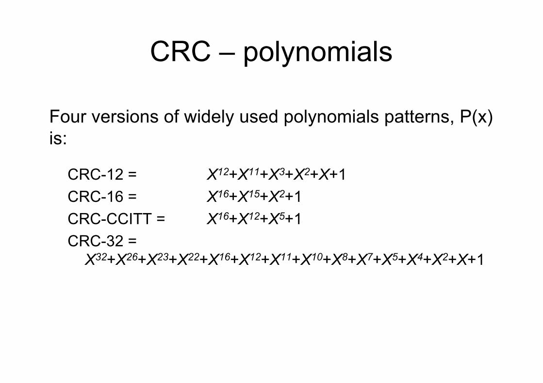
CRC-12 = X12+X11+X3+X2+X+1
CRC-16 = X16+X15+X2+1
CRC-CCITT = X16+X12+X5+1
CRC-32 =
X32+X26+X23+X22+X16+X12+X11+X10+X8+X7+X5+X4+X2+X+1
Four versions of widely used polynomials patterns, P(x)
is:

CRC – digital logic
1. The shift register contains n - k bits, equal to the length of the FCS.
2. There are up to n - k XOR gates.
3. The presence or absence of a gate corresponds to the polynomial,
P(x), excluding the terms 1 and Xn – k.
The CRC process can be implemented, as a dividing circuit
consisting of XOR gates and a shift register.
General architecture of the shift register implementation of a CRC for the
polynomial, P(X), where A0=An-k=1 and all other Ai equal either ’0’ or ’1’.
0
( )n k
i
i
i
P X A X−
=
=∑

CRC – digital logic – exampleData D=1010001101=>
D(X) = X9+X7+X3+X2+1
Divisor P =110101=>
P(X) = X5+X4+X2+1

CRC – digital logic – example
• To produce the proper output two switches are used.
• The input data bits are fed in with both switches in position A.
• The result is that for the 10 first steps, the input bits are fed into
the shift register and also used as output bits.
• After the last data bit is processed, the shift register contains
the remainder (FCS).
• As soon as the last data bit is provided to the shift register ,
both switches are set to the B position.
• This has two effects (1) all of the XOR gates becomes pass
through (no bits are changed), and (2) as the shifting process
continuous, the 5 CRC bits are output.