Changing the Charge Distribution of b-Helical-Based ...nurith/publications/nano2.pdf · The...
9
Changing the Charge Distribution of b-Helical-Based Nanostructures Can Provide the Conditions for Charge Transfer Nurit Haspel,* David Zanuy, y Jie Zheng, z Carlos Aleman, y Haim Wolfson,* and Ruth Nussinov z§ *School of Computer Science Faculty of Exact Sciences, Tel Aviv University, Tel Aviv 69978, Israel; y Department of Chemical Engineering Escola Te ´ cnica Superior d’Enginyeria Industrial de Barcelona-Universitat Polite ´cnica de Catalunya, 08028 Barcelona, Spain; z Basic Research Program Science Applications International Corporation-Frederick, Center for Cancer Research Nanobiology Program National Cancer Institute, NCI-Frederick, Frederick, Maryland 21702; and § Sackler Institute of Molecular Medicine, Department of Human Genetics, Sackler Faculty of Medicine, Tel Aviv University, Tel Aviv 69978, Israel ABSTRACT In this work we present a computational approach to the design of nanostructures made of structural motifs taken from left-handed b-helical proteins. Previously, we suggested a structural model based on the self-assembly of motifs taken from Escherichia coli galactoside acetyltransferase (Protein Data Bank 1krr, chain A, residues 131–165, denoted krr1), which produced a very stable nanotube in molecular dynamics simulations. Here we modify this model by changing the charge distribution in the inner core of the system and testing the effect of this change on the structural arrangement of the construct. Our results demonstrate that it is possible to generate the proper conditions for charge transfer inside nanotubes based on assemblies of krr1 segment. The electronic transfer would be achieved by introducing different histidine ionization states in selected positions of the internal core of the construct, in addition to specific mutations with charged amino acids that altogether will allow the formation of coherent net- works of aromatic ring stacking, salt-bridges, and hydrogen bonds. INTRODUCTION Nanotechnology aims to design novel materials and molec- ular devices, often via self-assembly of large molecules. In nature, protein domains often self-assemble and create large complexes of well-defined structure and function. Exploiting the natural ability of protein molecules to self-assemble can be a very useful approach in the design and construction of novel molecular structures (1–2). Many studies describe the use of natural and artificial peptides and DNA and RNA segments in nanodesign (3–11). Self-assembly of peptide segments can become a favorable route to obtain nanostructures, particu- larly those consisting of single or associated tubes, fibers, and vesicles. Binding mechanisms in self-assembly are robust and governed primarily by the protein’s native topology (12). Previously we suggested (13) that it is possible to construct nanostructures based on relatively large (;35 amino acid long) motifs taken from naturally occurring proteins. Specif- ically, we focused on structures made of the assembly of segments taken from left-handed b-helical proteins. The tubular nature of left-handed b-helical proteins makes them excellent candidates to be used as building blocks to construct fibrillar or tubular nanostructures without the need to perform many structural manipulations. In addition, their helical and symmetric structure makes them good candidates to be excised and tested as modules. To construct our nanosystems, we selected short (two turns) repetitive motifs and extracted the corresponding coordinates from the Protein Data Bank (PDB) (14). We assembled copies of the motifs on top of one another and simulated them for long periods. Of the systems we tested, the construct based on the assembly of copies of residues 131–165 of galactoside acetyltransferase from Escherichia coli (PDB code: 1krr, chain A) showed a re- markable structural stability over a long period of simulation time (20–40 ns) under all the tested temperature and ionic strength conditions. The system was denoted krr1. Fig. 1 shows the krr1 sequence and structure. In this study we start with the krr1 structure we obtained previously (13) and aim to modify it toward useful biological functions. This construct is characterized by an internal hydrophobic core containing mainly valine and isoleucine residues, rendering it inappropriate for the transfer of matter or charge. Since the hollow space inside the structure we obtained is narrow and unsuitable for the transfer of large molecules, charge transfer seems to be one natural applica- tion. However, to allow charge transfer the chemistry of the internal core of the structure should be modified. Charge can be transferred through p-electron stacking or through H 1 transfer. We cannot directly simulate charge transfer through classical mechanics, but we can assess whether there are suf- ficient conditions to potentially allow it. We can either create ladders of p-electron-rich functional groups by substituting some of the original residues in the interior of the construct by other residues capable of p-stacking or generate a proton transfer environment through a network of salt bridges, reminiscent of the serine protease catalytic triad. The two necessary conditions to achieve this goal are Submitted November 15, 2006, and accepted for publication February 23, 2007. Address reprint requests to David Zanuy, Dept. of Chemical Engineering, ETSEIB-UPC, Diagonal 647, 08028 Barcelona, Spain. Tel.: 34-93-405- 4447; Fax: 34-93-401-7150; E-mail: [email protected]; or Ruth Nussinov, Center Cancer Research Nanobiology Program, NCI-Frederick, Bldg. 469, Rm. 151, Frederick, MD 21702. Tel.: 301-846-5579; Fax: 301-846-5598; E-mail: [email protected]. Editor: Robert Callender. Ó 2007 by the Biophysical Society 0006-3495/07/07/245/09 $2.00 doi: 10.1529/biophysj.106.100644 Biophysical Journal Volume 93 July 2007 245–253 245
Transcript of Changing the Charge Distribution of b-Helical-Based ...nurith/publications/nano2.pdf · The...

Changing the Charge Distribution of b-Helical-Based Nanostructures CanProvide the Conditions for Charge Transfer
Nurit Haspel,* David Zanuy,y Jie Zheng,z Carlos Aleman,y Haim Wolfson,* and Ruth Nussinovz§
*School of Computer Science Faculty of Exact Sciences, Tel Aviv University, Tel Aviv 69978, Israel; yDepartment of Chemical EngineeringEscola Tecnica Superior d’Enginyeria Industrial de Barcelona-Universitat Politecnica de Catalunya, 08028 Barcelona, Spain; zBasic ResearchProgram Science Applications International Corporation-Frederick, Center for Cancer Research Nanobiology Program National Cancer Institute,NCI-Frederick, Frederick, Maryland 21702; and §Sackler Institute of Molecular Medicine, Department of Human Genetics, Sackler Faculty ofMedicine, Tel Aviv University, Tel Aviv 69978, Israel
ABSTRACT In this work we present a computational approach to the design of nanostructures made of structural motifs takenfrom left-handed b-helical proteins. Previously, we suggested a structural model based on the self-assembly of motifs taken fromEscherichia coli galactoside acetyltransferase (Protein Data Bank 1krr, chain A, residues 131–165, denoted krr1), which produceda very stable nanotube in molecular dynamics simulations. Here we modify this model by changing the charge distribution in theinner core of the system and testing the effect of this change on the structural arrangement of the construct. Our results demonstratethat it is possible to generate the proper conditions for charge transfer inside nanotubes based on assemblies of krr1 segment. Theelectronic transfer would be achieved by introducing different histidine ionization states in selected positions of the internal core ofthe construct, in addition to specific mutations with charged amino acids that altogether will allow the formation of coherent net-works of aromatic ring stacking, salt-bridges, and hydrogen bonds.
INTRODUCTION
Nanotechnology aims to design novel materials and molec-
ular devices, often via self-assembly of large molecules. In
nature, protein domains often self-assemble and create large
complexes of well-defined structure and function. Exploiting
the natural ability of protein molecules to self-assemble can be
a very useful approach in the design and construction of novel
molecular structures (1–2). Many studies describe the use of
natural and artificial peptides and DNA and RNA segments in
nanodesign (3–11). Self-assembly of peptide segments can
become a favorable route to obtain nanostructures, particu-
larly those consisting of single or associated tubes, fibers, and
vesicles. Binding mechanisms in self-assembly are robust and
governed primarily by the protein’s native topology (12).
Previously we suggested (13) that it is possible to construct
nanostructures based on relatively large (;35 amino acid
long) motifs taken from naturally occurring proteins. Specif-
ically, we focused on structures made of the assembly of
segments taken from left-handed b-helical proteins. The
tubular nature of left-handed b-helical proteins makes them
excellent candidates to be used as building blocks to construct
fibrillar or tubular nanostructures without the need to perform
many structural manipulations. In addition, their helical and
symmetric structure makes them good candidates to be
excised and tested as modules. To construct our nanosystems,
we selected short (two turns) repetitive motifs and extracted
the corresponding coordinates from the Protein Data Bank
(PDB) (14). We assembled copies of the motifs on top of one
another and simulated them for long periods. Of the systems
we tested, the construct based on the assembly of copies
of residues 131–165 of galactoside acetyltransferase from
Escherichia coli (PDB code: 1krr, chain A) showed a re-
markable structural stability over a long period of simulation
time (20–40 ns) under all the tested temperature and ionic
strength conditions. The system was denoted krr1. Fig. 1
shows the krr1 sequence and structure.
In this study we start with the krr1 structure we obtained
previously (13) and aim to modify it toward useful biological
functions. This construct is characterized by an internal
hydrophobic core containing mainly valine and isoleucine
residues, rendering it inappropriate for the transfer of matter
or charge. Since the hollow space inside the structure we
obtained is narrow and unsuitable for the transfer of large
molecules, charge transfer seems to be one natural applica-
tion. However, to allow charge transfer the chemistry of the
internal core of the structure should be modified. Charge can
be transferred through p-electron stacking or through H1
transfer. We cannot directly simulate charge transfer through
classical mechanics, but we can assess whether there are suf-
ficient conditions to potentially allow it. We can either create
ladders of p-electron-rich functional groups by substituting
some of the original residues in the interior of the construct
by other residues capable of p-stacking or generate a proton
transfer environment through a network of salt bridges,
reminiscent of the serine protease catalytic triad. The two
necessary conditions to achieve this goal are
Submitted November 15, 2006, and accepted for publication February 23,
2007.
Address reprint requests to David Zanuy, Dept. of Chemical Engineering,
ETSEIB-UPC, Diagonal 647, 08028 Barcelona, Spain. Tel.: 34-93-405-
4447; Fax: 34-93-401-7150; E-mail: [email protected]; or Ruth Nussinov,
Center Cancer Research Nanobiology Program, NCI-Frederick, Bldg. 469,
Rm. 151, Frederick, MD 21702. Tel.: 301-846-5579; Fax: 301-846-5598;
E-mail: [email protected].
Editor: Robert Callender.
� 2007 by the Biophysical Society
0006-3495/07/07/245/09 $2.00 doi: 10.1529/biophysj.106.100644
Biophysical Journal Volume 93 July 2007 245–253 245

1. The mutated structures must still retain their tubular struc-
tural organization in the simulation.
2. There must be a side-chain distribution that allows the
chemical processes mentioned above.
To create a ladder of p-stacking residues and to test
whether this would affect the structural organization, we
inserted a row of histidine residues in each of the three
b-sheets, one sheet at a time (see Fig. 2 for an illustration of
the three basic histidine mutants) and simulated the mutated
structures. Histidine is a good choice of an amino acid for this
purpose. It is aromatic and therefore capable of p-electron
stacking. Its side chain resembles, more or less, the size of
valine and isoleucine so we can expect that no drastic steric
hindrance should occur. In addition, its pKa is 6, which means
that in a physiological pH it can assume both a neutral and a
charged form with a relatively high probability. Moreover, its
neutral form is actually equilibrium between two states: one
with d hydrogen (ND) protonated and the other with e hydro-
gen (NE) protonated. This allows us to test different possible
combinations of ionization states. Naturally, we could not
sample all the possible ionization states due to computational
time limitations, but we tried to sample as many possible po-
sitions as feasible to insert the histidines, as well as different
combinations of ionization states. We identified a position
where despite the insertion of histidine the simulated system
retained its initial organization to a reasonable extent and
created a configuration made of networks of neutral histidine,
charged histidine, and aspartate, imitating the serine protease
catalytic triad. We suggest a structure with a row of alterna-
tively neutral and charged histidine residues that interact with
a row of aspartate residues through salt bridges and with each
other through aromatic ring stacking and thus provide the con-
ditions for creating a nanosystem capable of charge transfer.
METHODS
The calculations were performed using the NAMD package (15). All the
atoms of the system were considered explicitly, and the energy was
calculated using the CHARMM22 force field (16). Water molecules were
represented explicitly, using the TIP3 model (17). The simulations were
performed using the NVT ensemble in an orthorhombic simulation box. We
chose constant volume simulations because all the trajectories were obtained
at high temperature. By these means we could assure not losing a proper
density distribution due to thermal effects. Periodic boundary conditions
were applied using the nearest image convention. The box size was adjusted
to fit the complex size, so that infinite dilution conditions would be main-
tained. The box dimensions were 50 3 50 3 70 A to ensure infinite dilution.
Some systems were simulated in a bounding box of size 60 3 60 3 80 A.
Each system contained ;15,000–20,000 atoms including the solvent (or
27,000–30,000 in the structures with the larger bounding box). The starting
molecular structures were built using the INSIGHTII molecular package
(2000, Accelrys, San Diego, CA). For any given arrangement we fixed the
interturn distance of adjacent repetitive units to match the interstrand
distance within each unit, which was ;4.5 A. The charge of all potential
titratable groups was fixed at these values corresponding to neutral pH, such
that all aspartic acid side chains were represented in their anionic form and
all lysine side chains in their acidic positively charged form. Both peptide
edges were capped to avoid interactions between adjacent termini.
We performed the simulations with ionic strength of 0.8% w/w (;24
ions) at 300� K. We kept the overall charge of the system neutral for the use
of particle mesh Ewald summation (18) to calculate the electrostatic charges.
The ions were chloride and sodium. The molecular dynamics protocol we
used here has been used in our research group for some years (13,19–23)
and has been proven to correspond to the experimental results (22,24–26).
Before running each molecular dynamics simulation, the potential energy of
each system was minimized using 5000 conjugate gradient steps. The
heating protocol included 15 ps of increasing the temperature of the system
from 0� to the final temperature of 300� K plus 1 ns of equilibration period.
FIGURE 2 The basic units of krr1 with inserted histidine. Each of the three
subfigures depicts a different position in which the histidine was inserted. (A)
The histidine substitutes residues I-146 and V-164 (denoted krr_his1). (B)
The histidine substitutes residues I-140 and I-158 (denoted krr_his2). (C) The
histidine substitutes residues 134 and 152 (denoted krr_his3).
FIGURE 1 Sequence and structure of the construct made of residues 131–
165 of E. coli galactoside acetyltransferase (PDB 1krr). On the left – a side
view. Right – front view. Bottom – sequence alignment.
246 Haspel et al.
Biophysical Journal 93(1) 245–253
A residue-based cutoff was applied at 14 A, i.e., if any two molecules had
any atoms within 14 A, the interaction between them was evaluated. A
numerical integration time step of 1 fs was used for all the simulations. The
nonbonded pair list was updated every 20 steps, and the trajectories were
saved every 1000 steps (1 ps) for subsequent analysis. Each simulation was
run for a period of 20 ns.
Structural analysis
Regarding conservation of the size of the structure with respect to the
minimized structure, the trajectories were aligned with the initial structure
and the root mean-square deviation (RMSD) was calculated with respect to
C-a atoms. The trajectories were sampled every 10 ps. The main-chain
dihedral angles were sampled every 20 ps to maintain a good sampling of the
trajectories but avoid a dense plot. The plots were generated with MATLAB.
The figures were generated using MATLAB, VMD (27), and Rasmol (28).
RESULTS AND DISCUSSION
System description
The systems we constructed and simulated consisted of four
repeats of a basic two-turn unit, containing altogether eight
strand-loop motifs stacked on one another. Each basic re-
petitive unit was based on the PDB file of Galactoside acetyl-
transferase from E. coli (PDB code: 1krr, chain A, residues
131–165) and was represented at the atomic level.
Overall, we had nine histidine mutants, each with a
different combination of protonation states (see Table 1). All
systems were simulated in a water box for a period of 20 ns at
300� K. The simulations were performed using the NAMD
program (15) (see Methods for a detailed description of the
simulation conditions). To validate our results in an environ-
ment which is more reminiscent of physiological conditions,
we added sodium and chloride ions to the solution and used
the particle mesh Ewald summation (18) to evaluate the effect
of ionic strength on the structural organization of our models.
We used 24 ions, which leads to an ionic concentration of
0.8%, which is approximately the physiological concentra-
tion, keeping the overall charge of the system neutral to enable
the Ewald summation. Fig. 3 shows the evolution of the
RMSD with respect to the initial (minimized) structure of all
the histidine-based simulated systems over time. We consid-
ered only the Ca atoms in the RMSD calculation, since side-
chain atoms are flexible and calculating the evolution of their
RMSD may introduce noise into the measurement.
For reference, we repeated the simulation of the wild-type
krr1 under the same conditions and plotted the result in Fig. 3
A. As seen in the figure, some of the systems lasted well and
kept their structural organization throughout the simulation,
whereas other systems lost their structural organization to a
considerable extent. The most stable system we obtained was
when residues I-146 and V-164 (placed on top of one another
in consecutive turns) were replaced by a neutral histidine
with ND or NE protonated (denoted hsd1/hse1 mutants,
respectively). Other structures were also able to maintain
their structural arrangement to a degree, after the insertion of
histidine (see the RMSD analysis in Fig. 3 and the structures
before and after the simulations in Fig. 4). Since the neutral
state in which the ND is protonated is more common in
nature, we selected the hsd1 mutant as a reference structure
for further simulations, as described below.
The ‘‘serine triad’’-like configuration
The concept that residues such as histidine can be placed
inside a nanostructure brings to mind the possibility of using
the nanostructures we designed as electron transfer devices
(S. Kent, University of Chicago, personal communication,
2005). Histidines on consecutive strands are capable of
stacking on one another, and the overlap between their p-
electrons can potentially be used—along with a set of charged
residues to supply the charge—for electron transfer.
We thus further modified the krr_hsd1 mutant, which is
shown above to be structurally stable. We created a triad of
amino acids, following the serine protease catalytic triad
proton transfer system common in nature. As is well known,
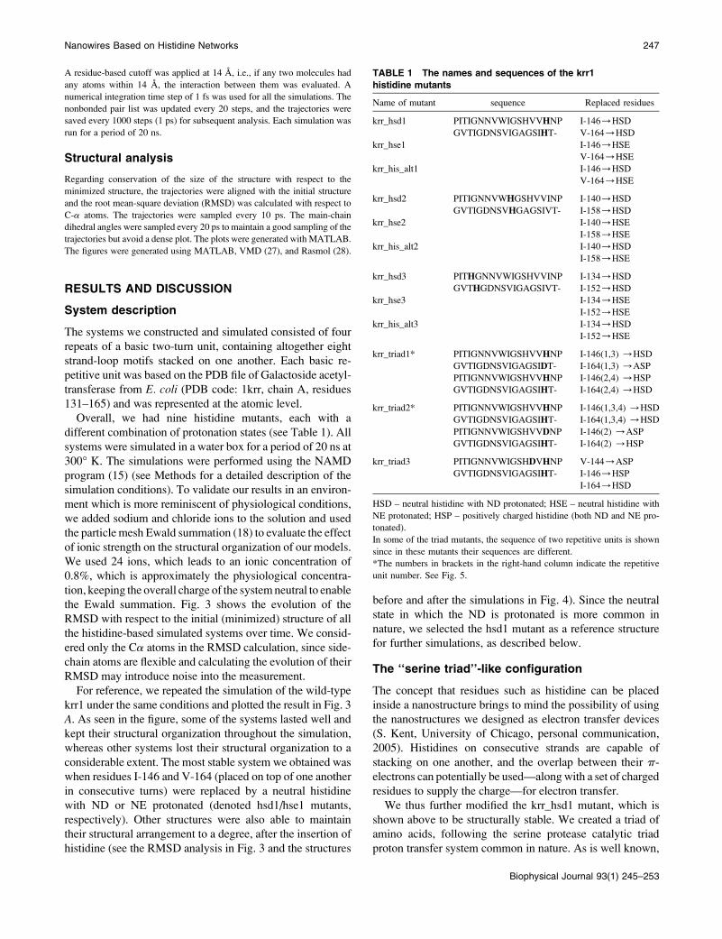
TABLE 1 The names and sequences of the krr1
histidine mutants
Name of mutant sequence Replaced residues
krr_hsd1 PITIGNNVWIGSHVVHNP
GVTIGDNSVIGAGSIHT-
I-146/HSD
V-164/HSD
krr_hse1 I-146/HSE
V-164/HSE
krr_his_alt1 I-146/HSD
V-164/HSE
krr_hsd2 PITIGNNVWHGSHVVINP
GVTIGDNSVHGAGSIVT-
I-140/HSD
I-158/HSD
krr_hse2 I-140/HSE
I-158/HSE
krr_his_alt2 I-140/HSD
I-158/HSE
krr_hsd3 PITHGNNVWIGSHVVINP
GVTHGDNSVIGAGSIVT-
I-134/HSD
I-152/HSD
krr_hse3 I-134/HSE
I-152/HSE
krr_his_alt3 I-134/HSD
I-152/HSE
krr_triad1* PITIGNNVWIGSHVVHNP
GVTIGDNSVIGAGSIDT-
PITIGNNVWIGSHVVHNP
GVTIGDNSVIGAGSIHT-
I-146(1,3) /HSD
I-164(1,3) /ASP
I-146(2,4) /HSP
I-164(2,4) /HSD
krr_triad2* PITIGNNVWIGSHVVHNP
GVTIGDNSVIGAGSIHT-
PITIGNNVWIGSHVVDNP
GVTIGDNSVIGAGSIHT-
I-146(1,3,4) /HSD
I-164(1,3,4) /HSD
I-146(2) /ASP
I-164(2) /HSP
krr_triad3 PITIGNNVWIGSHDVHNP
GVTIGDNSVIGAGSIHT-
V-144/ASP
I-146/HSP
I-164/HSD
HSD – neutral histidine with ND protonated; HSE – neutral histidine with
NE protonated; HSP – positively charged histidine (both ND and NE pro-
tonated).
In some of the triad mutants, the sequence of two repetitive units is shown
since in these mutants their sequences are different.
*The numbers in brackets in the right-hand column indicate the repetitive
unit number. See Fig. 5.
Nanowires Based on Histidine Networks 247
Biophysical Journal 93(1) 245–253

this triad contains a Ser-His-Asp motif and a proton is
transferred via the histidine changing its ionization state,
with the serine being the hydrogen donor. Our triad was
slightly different, using a neutral histidine instead of the
serine to be the hydrogen-bond acceptor. Fig. 5 shows the
structures of the histidine-aspartate triads.
We simulated three triad-containing structures for a period
of 20 ns each (see Methods). The triad mutants differ from
one another in the number of triads and their position in the
structure. Fig. 5 shows the triad-containing structures. Fig. 3
D presents the RMSD of the triad systems throughout the
simulations. The RMSD was measured with respect to the
minimized structures, and only the Ca atoms were consid-
ered. As can be seen, all three triad structures got to within
;2.5–3 A from the original structures. The construct
denoted triad3 (whose structure is shown in detail in Fig. 5
C) is the most stable. Its structure adapts its conformation
slightly in the first few nanoseconds of the simulations and
later remains stable, and its RMSD hardly changes at all
throughout the rest of the simulation. In this structure we
inserted a row of alternatively neutral and charged histidine
residues substituting residues Ile-146 and Val-164. Another
row of aspartate residues replaced nearby residue Val-144.
As can be seen in Fig. 5 C, the aspartate residues interact
with the charged histidines, creating a network of salt
bridges, whereas the neutral histidines take up the remaining
space, avoiding a steric clash. The other triad structures did
not fall apart either, but their terminal repetitive units started
to fray, which indicates that given more time they would
probably fall apart completely. To find out which parts of the
structure fluctuated more than others during the simulation,
we also analyzed the backbone conformational changes
during the simulation.
Fig. 6 shows the distribution of the main-chain dihedral
angles of the loop residues in the triad3 mutant. For
comparison, Fig. 7 shows the distribution of the main-chain
dihedral angles of the same residues in the krr1 wild-type. As
mentioned above, residue 144 was mutated to Asp in triad3
and as can be seen in Fig. 6, C and D, the loop containing
residues 141–144 and 159–162 fluctuated more than the
other two loops (shown in Fig. 6, A, B, and D), as its residues
explored a wider range of the conformational space. More-
over, that loop is considerably less stable in the triad3 mutant
than the equivalent loop in the krr1 wild-type (shown in Fig.
7, C and D). However, residues 146 and 164, which were
mutated to histidine in the triad3 system and are located on
the adjacent b-sheet, did not fluctuate much (results not
shown). Despite this, the triad3 structure was still able to
maintain its overall organization. This can be rationalized by
the following: The mutated loop had to readapt its structure
since it was subject to additional conformational restrictions
imposed by the salt bridges formed by the interaction between
the Asp-144 side chain and the nearby charged histidine side
chain (see Fig. 5). However, as seen in Fig. 6 C, it was Gly-
141, which was located at the other end of the loop, that
fluctuated the most during the simulation and explored the
widest range of dihedral angles, whereas Asp-144 remained
within a narrower range of side-chain conformations. This is
FIGURE 3 RMSD plot of the histidine mu-
tants. The plot was divided into four panels for
convenience: (A) neutral histidine, ND proton-
ated; (B) neutral histidine, NE protonated; (C)
neutral histidine, ND and NE protonated alter-
natively; and (D) his-asp-his1 triad containing
systems. The system denoted triad3 was simu-
lated twice for verification. The 1,2,3 annotations
in panels A–C indicate mutants a, b, and c, re-
spectively, as seen in Fig. 2. The wild-type krr1 is
presented in (A) for reference.
248 Haspel et al.
Biophysical Journal 93(1) 245–253

expected, since Asp-144 was restricted by the salt bridges
with the nearby histidine side chain. We assume that due to
the flexibility of the glycine, it absorbed most of the extra
conformational restrictions and therefore helped keep the
overall organization of the structure largely intact.
Interaction analysis
The histidine mutants are characterized by stacking interac-
tions between the aromatic rings of histidine residues on
equivalent positions on consecutive strands in the interior core
of the structure. In addition, the triad3 mutant is characterized
FIGURE 5 Three examples of the triad-containing struc-
tures: (A) triad1, (B) triad2, (C) triad3. In all cases on the
left: only the triad. On the right: the entire system with the
triad-containing row emphasized. The triad in A and B is
emphasized and circled in black on the left. The salt bridge
interactions are indicated by arrows in C.
FIGURE 4 The three triad-containing systems
before (left) and after (right) the simulation.
(A) krr_triad1, (B) krr_triad2, (C) krr_triad3.
The histidine residues are emphasized for clar-
ity: neutral histidine is depicted in cyan, and
charged histidine is depicted in yellow. The
aspartate residues taking part in the triad are
depicted in red. See Fig. 5 for a detailed
description of the triads.
Nanowires Based on Histidine Networks 249
Biophysical Journal 93(1) 245–253

by a network of salt bridges between the negatively charged
side chain of Asp-144 and the positively charged Hsp-164
(see an illustration of these interactions in Fig. 5 C). Table 2
summarizes the average salt-bridge distance between the Cg
of Asp-144 and the positively charged nitrogen atoms of
Hsp-164 for both simulations of triad3. We considered an
interaction as a salt bridge if the distance between the Asp
Cg atom and any of the Hsp-charged hydrogen atoms was
#3.0 A. We considered the distance to the Cg atom instead
of to the charged oxygen atoms of Asp (Od1 and Od2), since
side-chain conformational changes during the simulation
often cause the two oxygen atoms to flip. Therefore, mea-
suring the distance of the Cg from the positively charged
histidine hydrogen is more robust and provides a good
estimate as to the location of the Od1 and Od2 atoms with
respect to the His positively charged group.
As seen in the table, the average distance of interaction for
the salt bridges is ;2.7 A in both simulations, which indi-
cates a strong electrostatic attraction, since the charged Asp
oxygen atoms are even closer to the Hsp hydrogens than the
Asp Cg. It is also seen that nearly all seven possible inter-
actions existed at any given trajectory during the simulation
and that the standard deviation of the measured distance was
small (;60.2 A), indicating that the distances were rather
restrained and did not change much during the simulation,
in accordance with the fact that the structure in general
maintained its organization. Table 2 also shows the average
distance and angle of the aromatic ring stacking between
consecutive histidine residues in both the triad3 mutants and
the hsd1 mutant, whose basic repetitive unit is shown in Fig.
2 A. We considered a maximum distance of 7.0 A between
the centers of masses of the measured rings. As seen in the
table, the average stacking distance is 4.9–5.2 A. In addition,
all seven possible stacking interactions existed in nearly all
the simulations, especially in the two triad3 simulations. The
standard deviations were also rather small, considerably less
than 1.0 A in all cases, indicating that the distances between
consecutive histidine rings did not fluctuate much during the
simulation, again in accordance with the overall good orga-
nization of the structures.
FIGURE 6 The main-chain dihedral angle
distribution of the loop residues of the krr_triad3
mutant. For loop assignment, see bottom right
illustration.
250 Haspel et al.
Biophysical Journal 93(1) 245–253

Looking at the average angle between consecutive aro-
matic rings, also shown in the table, one can see that not
surprisingly in the hsd1 mutant the aromatic ring’s stacking
was significantly more parallel than in the triad3 mutants,
where the stacking tended to be T-shaped. In the triad3
mutants the positively charged histidine rings adapted their
conformation to interact with the Asp-144 oxygens and
created the energetically preferred electrostatic interactions.
The remaining neutral histidine rings could not align with the
charged rings, as this would cause a steric clash with the Asp
residues (see Fig. 5 C) and therefore the stacking angles were
closer to 90�. Despite the fact that T-shaped stacking is weaker
than parallel stacking, it is still strong enough to potentially
enable a partial overlap of the p-electrons of the rings. To
prove that T-shaped stacking is a consequence of the nano-
construct organization more than the effect of adding to
stacking the electrostatic component (Asp�-His1 pairs), we
performed quantum mechanical calculations using molecular
models that mimic the triad organization. Results indicated
that T-shape stacking is disfavored with respect to classical
face to face stacking, even when electrostatic interactions are
involved. Therefore, the steric restrictions imposed by the
nanostructure organization are responsible for the formation
of a T-shaped arrangement since they are energetically less
FIGURE 7 The main-chain dihedral angle dis-
tribution of the loop residues of the wild-type
krr1, when simulated with 24 ions (0.8% w/w).
For loop assignment, see bottom right illustration.
TABLE 2 Average distance of salt bridges and aromatic ring stacking in the relevant histidine mutants
Mutant
name
Average salt
bridge (A)
Average number
of salt bridges*
Average aromatic
ring distance (A)
Average aromatic
ring angle (degrees)
Average number of
ring stacking*
krr_hsd1 N/A N/A 4.944 6 0.47 28.12 6 14.56 5.997
krr_triad3 (I) 2.72 6 0.14 6.62 5.20 6 0.89 71.01 6 23.97 6.75
krr_triad3 (II) 2.70 6 0.2 6.07 5.19 6 0.68 63.37 6 18.04 6.59
*Out of seven possible interactions.
Nanowires Based on Histidine Networks 251
Biophysical Journal 93(1) 245–253

favored (results are shown in the Supplementary Material).
The overall scenario drawn by our results demonstrates a
potential use of the krr1-based models to transfer charge.
CONCLUSIONS
We have shown before that b-helical proteins are promising
candidates for nanostructure design for several reasons: They
are repetitive, tubular, and symmetrical and thus suitable for
designing new nanomaterials of a repetitive nature such as
nanofibers and tubes. In addition, their tube-like structure
makes them of potential use for targeted small molecule
delivery, fiber construction with attached imaging probes, or
targeted peptides and charge transfer. We were able to show
that a system constructed of four replicas of residues 131–
165 of galactoside acetyltransferase exhibited remarkable
stability under all the simulated conditions, including tem-
perature increase and addition of ions. In this work we take
our findings one step further and show that we can modify
the original sequence of our construct and substitute specific
residues in the internal core by histidine while maintaining
the original structure throughout the simulation time. This, in
turn, shows that it is possible to modify the residue com-
position and the hydrophobicity of the interior core of a
b-helical-based construct and still maintain structural orga-
nization. We also inserted a row of aspartate residues in a
position that enabled the creation of a network of salt bridges
and hydrogen bonds with the histidine side chains, follow-
ing the serine protease catalytic triad seen in nature, while
largely maintaining the original structural organization. This
suggests that there is potential use of these systems for
charge transfer. This hypothesis requires further testing and
experimenting. Further research directions may include more
extensive simulations, including the introduction of point
mutations to standard and nonstandard amino acids to en-
hance the structural stability of the systems. Another di-
rection of future study could be to perform more quantum
mechanical calculations to test the hypothesis that the triad-
containing constructs are suitable for charge transfer. Another
direction would be to experimentally produce the constructs
and test their structural stability in vitro.
SUPPLEMENTARY MATERIAL
An online supplement to this article can be found by visiting
BJ Online at http://www.biophysj.org.
We thank Steve Kent who, during his visit to the NCI-Frederick in the
summer of 2005, suggested the usage of the self-assembled b-helices’
repeats for electron transfer. Computation times are provided by the
National Cancer Institute’s Frederick Advanced Biomedical Supercomput-
ing Center and by the NIH Biowulf.
This project has been funded in whole or in part with federal funds from
the National Cancer Institute, National Institutes of Health (NIH), under
contract number NO1-CO12400. The content of this publication does not
necessarily reflect the view or policies of the Department of Health and
Human Services, nor does mention of trade names, commercial products, or
organization imply endorsement by the U.S. government. This research was
supported (in part) by the Intramural Research Program of the NIH,
National Cancer Institute, Center for Cancer Research. Part of the computer
resources was generously provided by the Barcelona Supercomputer Center
(BSC).
REFERENCES
1. Zhang, S., D. M. Marini, W. Hwang, and S. Sansoto. 2002. Design ofnanostructured biological materials through self-assembly of peptidesand proteins. Curr. Opin. Chem. Biol. 6:865–871.
2. Zhang, S. 2003. Fabrication of novel biomaterials through molecularself assembly (review). Nat. Biotechnol. 21:1171–1178.
3. Rajagopal, K., and J. P. Schneider. 2004. Self-assembling peptidesand proteins for nanotechnological applications (review). Curr. Opin.Struct. Biol. 14:480–486.
4. Claussen, R. C., B. M. Rabatic, and S. I. Stupp. 2003. Aqueous self-assembly of unsymmetric peptide bolaamphiphiles into nanofibers withhydrophilic cores and surfaces. J. Am. Chem. Soc. 125:12680–12681.
5. Percec, V., A. E. Dulcey, V. S. Balagurusamy, Y. Miura, J. Smidrkal,M. Peterca, S. Nummelin, U. Edlund, S. D. Hudson, P. A. Heiney,H. Duan, S. N. Magonov, and S. A. Vinogradov. 2004. Self-assemblyof amphiphilic dendritic dipeptides into helical pores. Nature. 430:764–768.
6. Reches, M., and E. Gazit. 2003. Casting metal nanowires within dis-crete self-assembled peptide nanotubes. Science. 300:625–627.
7. Matsuura, K., K. Murasato, and N. Kimizuka. 2005. Artificial peptide-nanospheres self-assembled from three-way junctions of beta sheet form-ing peptides. J. Am. Chem. Soc. 127:10148–10149.
8. Holowka, E., D. J. Pochan, and T. J. Deming. 2005. Charged polypep-tide vesicles with controllable diameter. J. Am. Chem. Soc. 127:12423–12428.
9. Hall, C. K., and V. A. Wagoner. 2006. Computational approaches tofibril structure and formation. Methods Enzymol. 412:338–365.
10. Iengar, P., N. V. Joshi, and P. Balaram. 2006. Conformational andsequence signatures in beta helix proteins. Structure. 14:529–542.
11. Elber, R. 2005. Long-timescale simulation methods. Curr. Opin.Struct. Biol. 15:151–156.
12. Levy, Y., and J. N. Onuchic. 2006. Mechanisms of protein assembly:lessons from minimalist models. Acc. Chem. Res. 39:135–142.
13. Haspel, N., D. Zanuy, C. Aleman, H. Wolfson, and R. Nussinov. 2006.De-novo tubular nanostructure design based on self-assembly of beta-helical protein motifs. Structure. 14:1137–1148.
14. Bernstein, F. C., T. F. Koetzle, G. J. B. Williams, E. F. Meyer, M. D.Brice, J. R. Rodgers, O. Kennard, T. Shimanouchi, and M. Tasumi.1977. The Protein Data Bank: a computer-based archival file formacromolecular structures. J. Mol. Biol. 112:535–542.
15. Kale, L., R. Skeel, M. Bhandarkar, R. Brunner, A. Gursoy, N. Krawetz,J. Phillips, A. Shinozaki, K. Varadarajan, and K. Schulten. 1999.NAMD2: greater scalability for parallel molecular dynamics. J. Comput.Phys. 151:283–312.
16. MacKerell, J. A. D., D. Bashford, M. Bellott, R. L. J. Dunbrack,J. Evanseck, and M. J. Field. 1998. All-hydrogen empirical potentialfor molecular modeling and dynamic studies of proteins using theCHARMM22 force field. J. Phys. Chem. B. 102:3586–3616.
17. Jorgensen, W. L., J. Chandrasekhar, J. D. Madura, R. W. Impey, andM. L. Klein. 1982. Comparison of simple potential functions for simu-lating liquid water. J. Chem. Phys. 79:926–935.
18. Darden, T., D. York, and L. Pedersen. 1993. Particle mesh Ewald: anN*log(N) method for Ewald sums in large systems. J. Chem. Phys.98:10089–10092.
19. Ma, B., and R. Nussinov. 2002. Stabilities and conformations ofAlzheimer’s beta-amyloid peptide oligomers (A-b16–22, A-b16–35,A-b10–35): sequence effects. Proc. Natl. Acad. Sci. USA. 99:14126–14131.
252 Haspel et al.
Biophysical Journal 93(1) 245–253

20. Zanuy, D., B. Ma, and R. Nussinov. 2003. Short peptide amyloid
organization: stabilities and conformations of the islet amyloid peptide
NFGAIL. Biophys. J. 84:1–11.
21. Zanuy, D., and R. Nussinov. 2003. The sequence dependence of fiber
organization: a comparative molecular dynamics study of the islet amy-
loid polypeptide segments 22–27 and 22–29. J. Mol. Biol. 329:565–584.
22. Zanuy, D., Y. Porat, E. Gazit, and R. Nussinov. 2004. Peptide se-
quence and amyloid formation: molecular simulations and experimen-
tal study of a human islet amyloid polypeptide fragment and its analogs.
Structure. 12:439–455.
23. Haspel, N., D. Zanuy, B. Ma, H. Wolfson, and R. Nussinov. 2005. A
comparative study of amyloid fibril formation by residues 15–19 of the
human calcitonin hormone: a single beta-sheet model with a small
hydrophobic core. J. Mol. Biol. 345:1213–1227.
24. Petkova, A. T., Y. Ishii, J. J. Balbach, O. N. Antzutkin, R. D. Leapman,
F. Delaglio, and R. Tycko. 2002. A structural model for Alzheimer’s
b-amyloid fibrils based on experimental constraints from solid state
NMR. Proc. Natl. Acad. Sci. USA. 99:16742–16747.
25. Reches, M., Y. Porat, and E. Gazit. 2002. Amyloid fibril formation by
pentapeptide and tetrapeptide fragments of human calcitonin. J. Biol.
Chem. 277:35475–35480.
26. Luehrs, T., C. Ritter, M. Adrian, D. Riek-Loher, B. Bohrmann, H.
Doebeli, D. Schubert, and R. Riek. 2005. 3D structure of Alzheimer’s
amyloid b-(1–42) fibrils. Proc. Natl. Acad. Sci. USA. 102:17342–17347.
27. Humphrey, W., A. Dalke, and K. Schulten. 1996. VMD: visual molec-
ular dynamics. J. Mol. Graph. 14:33–38.
28. Sayle, R., and J. E. Milner-White. 1995. RasMol: biomolecular graph-
ics for all. Trends Biochem. Sci. 20:374.
Nanowires Based on Histidine Networks 253
Biophysical Journal 93(1) 245–253