Object Oriented Methodologies J.N.Kotuba SYST39409 - Object Oriented Methodologies 1.

CHANGE IMPACT ANALYSIS OF OBJECT-ORIENTED
SOFTWARE
ByMichelle L. Lee (Li Li)
A DissertationSubmitted to theGraduate Faculty
ofGeorge Mason UniversityIn Partial Fulfillment of
The Requirements for the Degreeof
Doctor of PhilosophyInformation Technology
Committee:
_____________________________ Jeff Offutt, Dissertation Director
_____________________________ David Rine, Chairman
_____________________________ Xiaoyang Sean Wang
_____________________________ Daniel Carr
_____________________________ Stephen G. Nash, Associate Dean for Graduate Studies and Research
_____________________________ Lloyd J. Griffiths, Dean, School of Information Technology and Engineering
Date: __________________ Fall 1998 George Mason University Fairfax, Virginia
CHANGE IMPACT ANALYSIS OF OBJECT-ORIENTED
SOFTWARE
A dissertation submitted in partial fulfillment of the requirements for the Doctor OfPhilosophy degree in Information Technology at George Mason University
By
Michelle L. Lee (Li Li)Master of Science
George Mason University, 1995
Thesis Director: Dr. Jeff Offutt, Associate ProfessorDepartment of Information and Software Engineering
Fall Semester 1998George Mason University
Fairfax, Virginia

ii
Copyright 1998 Michelle L. Lee (Li Li)All Rights Reserved
iii
DEDICATION
This dissertation is lovingly dedicated to my husband, Sheldon Zhou, for his endless
dedication and patience; my daughter, Stacey Zhou - who is very proud of her mom - for her
love and her company while I was working on the thesis; my farther, Jing Lee, for teaching
me to be myself and not to yield to difficulties; and my mother, GuoChai Fu, for teaching me
to be loving and responsible.

iv
ACKNOWLEDGMENTS
I want to offer my thanks to all who has contributed to the success of this research:
My dissertation director, Dr. A. Jefferson Offutt, for his guidance and encouragement;
Dr. David Rine, Dr. S. Sean Wang, and Dr. Danial Carr for serving on my committee and
providing me much needed support;
LCC International Inc for continuing moral and financial support and for allowing me use the
company software as part of the test cases of this research.
Olivier Jojic and Will Mitchell for providing their valuable comments and insights;
This research is partially supported by the National Science Foundation under grant CCR-98-
04111.
v
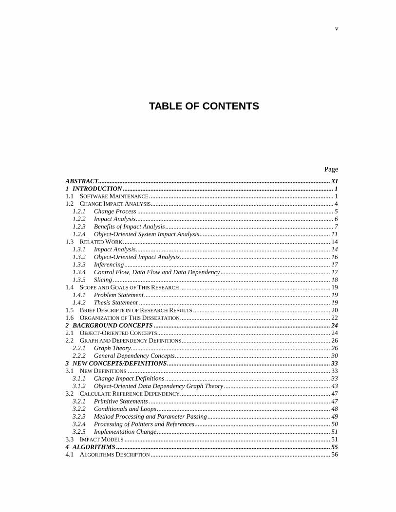
TABLE OF CONTENTS
Page
ABSTRACT.............................................................................................................................................. XI1 INTRODUCTION ................................................................................................................................. 11.1 SOFTWARE MAINTENANCE ................................................................................................................. 11.2 CHANGE IMPACT ANALYSIS................................................................................................................ 4
1.2.1 Change Process ........................................................................................................................ 51.2.2 Impact Analysis......................................................................................................................... 61.2.3 Benefits of Impact Analysis ....................................................................................................... 71.2.4 Object-Oriented System Impact Analysis................................................................................ 11
1.3 RELATED WORK............................................................................................................................... 141.3.1 Impact Analysis....................................................................................................................... 141.3.2 Object-Oriented Impact Analysis............................................................................................ 161.3.3 Inferencing.............................................................................................................................. 171.3.4 Control Flow, Data Flow and Data Dependency ................................................................... 171.3.5 Slicing ..................................................................................................................................... 18
1.4 SCOPE AND GOALS OF THIS RESEARCH ............................................................................................ 191.4.1 Problem Statement.................................................................................................................. 191.4.2 Thesis Statement ..................................................................................................................... 19
1.5 BRIEF DESCRIPTION OF RESEARCH RESULTS .................................................................................... 201.6 ORGANIZATION OF THIS DISSERTATION............................................................................................ 222 BACKGROUND CONCEPTS ............................................................................................................ 242.1 OBJECT-ORIENTED CONCEPTS.......................................................................................................... 242.2 GRAPH AND DEPENDENCY DEFINITIONS........................................................................................... 26
2.2.1 Graph Theory.......................................................................................................................... 262.2.2 General Dependency Concepts............................................................................................... 30
3 NEW CONCEPTS/DEFINITIONS.................................................................................................... 333.1 NEW DEFINITIONS ............................................................................................................................ 33
3.1.1 Change Impact Definitions ..................................................................................................... 333.1.2 Object-Oriented Data Dependency Graph Theory ................................................................. 43
3.2 CALCULATE REFERENCE DEPENDENCY............................................................................................ 473.2.1 Primitive Statements ............................................................................................................... 473.2.2 Conditionals and Loops .......................................................................................................... 483.2.3 Method Processing and Parameter Passing ........................................................................... 493.2.4 Processing of Pointers and References................................................................................... 503.2.5 Implementation Change.......................................................................................................... 51
3.3 IMPACT MODELS .............................................................................................................................. 514 ALGORITHMS ................................................................................................................................... 554.1 ALGORITHMS DESCRIPTION .............................................................................................................. 56
vi
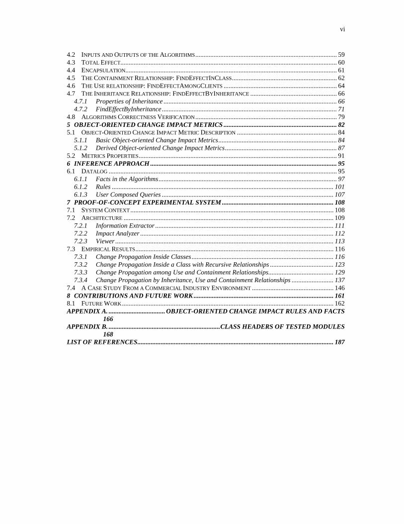
4.2 INPUTS AND OUTPUTS OF THE ALGORITHMS..................................................................................... 594.3 TOTAL EFFECT.................................................................................................................................. 604.4 ENCAPSULATION............................................................................................................................... 614.5 THE CONTAINMENT RELATIONSHIP: FINDEFFECTINCLASS............................................................... 624.6 THE USE RELATIONSHIP: FINDEFFECTAMONGCLIENTS .................................................................... 644.7 THE INHERITANCE RELATIONSHIP: FINDEFFECTBYINHERITANCE .................................................... 66
4.7.1 Properties of Inheritance ........................................................................................................ 664.7.2 FindEffectByInheritance ......................................................................................................... 71
4.8 ALGORITHMS CORRECTNESS VERIFICATION..................................................................................... 795 OBJECT-ORIENTED CHANGE IMPACT METRICS .................................................................... 825.1 OBJECT-ORIENTED CHANGE IMPACT METRIC DESCRIPTION ............................................................ 84
5.1.1 Basic Object-oriented Change Impact Metrics....................................................................... 845.1.2 Derived Object-oriented Change Impact Metrics................................................................... 87
5.2 METRICS PROPERTIES....................................................................................................................... 916 INFERENCE APPROACH ................................................................................................................ 956.1 DATALOG ......................................................................................................................................... 95
6.1.1 Facts in the Algorithms........................................................................................................... 976.1.2 Rules ..................................................................................................................................... 1016.1.3 User Composed Queries ....................................................................................................... 107
7 PROOF-OF-CONCEPT EXPERIMENTAL SYSTEM ................................................................... 1087.1 SYSTEM CONTEXT.......................................................................................................................... 1087.2 ARCHITECTURE .............................................................................................................................. 109
7.2.1 Information Extractor ........................................................................................................... 1117.2.2 Impact Analyzer .................................................................................................................... 1127.2.3 Viewer ................................................................................................................................... 113
7.3 EMPIRICAL RESULTS....................................................................................................................... 1167.3.1 Change Propagation Inside Classes ..................................................................................... 1167.3.2 Change Propagation Inside a Class with Recursive Relationships ...................................... 1237.3.3 Change Propagation among Use and Containment Relationships....................................... 1297.3.4 Change Propagation by Inheritance, Use and Containment Relationships ......................... 137
7.4 A CASE STUDY FROM A COMMERCIAL INDUSTRY ENVIRONMENT ................................................. 1468 CONTRIBUTIONS AND FUTURE WORK .................................................................................... 1618.1 FUTURE WORK............................................................................................................................... 162APPENDIX A. .................................. OBJECT-ORIENTED CHANGE IMPACT RULES AND FACTS
166APPENDIX B. ...................................................................CLASS HEADERS OF TESTED MODULES
168LIST OF REFERENCES...................................................................................................................... 187

vii
LIST OF TABLES
Table Page
1. Impact Power of Contaminate Type Values ................................................................................. 462. Object Relationship Type Values ................................................................................................. 46

viii
LIST OF FIGURES
Figure Page
1. Define the steps in the maintenance process [MORE90] ................................................................ 32. Typical Impact Analysis Process .................................................................................................. 103. Relationships between classes ...................................................................................................... 254. Class Components Graph.............................................................................................................. 345. Impact Model Dimension View.................................................................................................... 526. Impact Set Venn Diagram............................................................................................................. 547. Call Relationships among Change Impact Analysis Algorithms................................................... 558. Impact Set Component Graph....................................................................................................... 599. Total Effect Pseudo Code ............................................................................................................. 6010. Initialization Pseudo Code............................................................................................................ 6111. FindEffectInClass Pseudo Code ................................................................................................... 6412. FindEffectAmongClients pseudo code ......................................................................................... 6513. FindEffectByInheritance Pseudo Code......................................................................................... 7214. ForwardInheritanceTreeProcess(Cp)............................................................................................. 7415. BackwardInheritanceTreeProcess (Cc) ......................................................................................... 7416. Class Diagram of Inheritance Example......................................................................................... 7717. New FindEffectAmongClients Pseudo Code ................................................................................ 7918. Dependency Graph ....................................................................................................................... 9719. Inheritance Example ................................................................................................................... 10020. Method m references method n and data member y in C1.......................................................... 10221. Data member x in c1 references method m and data member y in c1......................................... 10222. Component Connection Graph ................................................................................................... 10923. Framework.................................................................................................................................. 11024. Information Collector Hierarchy................................................................................................. 11125. Analyzer Class Hierarchy. .......................................................................................................... 11226. ChAT Analyzer Class Diagram .................................................................................................. 11327. Class Member Dependencies in Example 7.3.1.......................................................................... 11728. All Class Tree View in Example 7.3.1........................................................................................ 11829. Impact Only Tree View in Example 7.3.1 .................................................................................. 11930. The Impact Table in Example 7.3.1............................................................................................ 12031. The Class Impact Table in Example 7.3.1 .................................................................................. 12132. Input Table in Example 7.3.1 ..................................................................................................... 12233. The recursive dependency in Example 7.3.2 .............................................................................. 12334. All Class Tree View in Example 7.3.2........................................................................................ 12435. Impact Only Tree View in Example 7.3.2 .................................................................................. 12536. Impact Table of Example 7.3.2................................................................................................... 12637. Class Impact Table of Example 7.3.2 ......................................................................................... 12738. Input Table in Example 7.3.2 ..................................................................................................... 12839. Example 7.3.3 header files.......................................................................................................... 129
ix
40. Example 7.3.3 Class Diagram..................................................................................................... 13041. Class Member Dependencies of Example 7.3.3.......................................................................... 13142. All Class Tree View of Example 7.3.3 ....................................................................................... 13243. Impact Only Tree View of Example 7.3.3 .................................................................................. 13344. Impact Table of Example 7.3.3................................................................................................... 13445. Class Impact Table of Example 7.3.3 ......................................................................................... 13546. Input Table of Example 7.3.3 ..................................................................................................... 13647. Inheritance Relationship Sample Code ....................................................................................... 13848. Class Diagram of Example 7.3.4 ................................................................................................ 13949. Class Member Dependencies in Example 7.3.4.......................................................................... 14050. All Class Tree View of Example 7.3.4 ....................................................................................... 14151. Impact Only Class Tree View in Example 7.3.4......................................................................... 14252. Impact Table of Example 7.3.4................................................................................................... 14353. Class Impact Table of Example 7.3.4 ......................................................................................... 14454. Input Table of Example 7.3.4 ..................................................................................................... 14555. Class Diagram of Notification Module ....................................................................................... 14756. Document Module Class Diagram.............................................................................................. 14857. Class Diagram of Graphic Module ............................................................................................. 14958. Example 7.4.1.4 All Class Tree View......................................................................................... 15059. Example 7.4.1.4 Impact Only Class Tree View.......................................................................... 15160. Example 7.4.1.4 Member Impact Table...................................................................................... 15261. Example 7.4.1.4 Class Impact Table .......................................................................................... 15362. Input Table of Example 7.4.1.4 .................................................................................................. 15463. Example 7.4.1.5 All Class Tree View......................................................................................... 15664. Example 7.4.1.5 Impact Only Class Tree View.......................................................................... 15765. Example 7.4.1.5 Impact Table.................................................................................................... 15866. Example 7.4.1.5 Class Impact Table .......................................................................................... 15967. The Input Table of Example 7.4.1.5 ........................................................................................... 160

ABSTRACT
CHANGE IMPACT ANALYSIS OF OBJECT-ORIENTED SOFTWARE
Michelle L. Lee (Li Li), Ph.D.
George Mason University, 1998
Dissertation Director: Dr. A. Jefferson Offutt
As the software industry has matured, we have shifted our resources from being devoted to
developing new software systems to making modifications in evolving software systems. A
major problem for developers in an evolutionary environment is that seemingly small
changes can ripple throughout the system to cause major unintended impacts elsewhere. As
such, software developers need mechanisms to understand how a change to a software
system will impact the rest of the system. Although the effects of changes in object-oriented
software can be restricted, they are also more subtle and more difficult to detect. Maintaining
the current object-oriented systems is more of an art, similar to where we were 15 years ago
with procedural systems, than an engineering skill. We are beginning to see "legacy" object-
oriented systems in industry. A difficult problem is how to maintain these objects in large,
complex systems. Although objects are more easily identified and packaged, features such as
encapsulation, inheritance, aggregation, polymorphism and dynamic binding can make the
ripple effects of object-oriented systems far more difficult to control than in procedural
systems. The research presented here addresses the problems of change impact analysis for
object-oriented software. Major results of this research include a set of object-oriented data
dependency graphs, a set of algorithms that allow software developers to evaluate proposed
changes on object-oriented software, a set of object-oriented change impact metrics to
evaluate the change impact quantitatively, and a prototype tool (ChaT) to evaluate the
algorithms. This research also results in efficient regression testing by helping testers decide
what classes and methods need to be retested, and in supporting cost estimation and schedule
planning.

1
1 INTRODUCTION
This dissertation presents results addressing the problem of change impact analysis on
object-oriented software. This chapter describes the basic concepts of software maintenance,
and introduces the concepts of change process and impact analysis, especially object-
oriented system impact analysis. It discusses what has been done in this research area, the
problems, and how this research addresses these problems.
1.1 Software Maintenance
Software evolution refers to the on-going enhancements of existing software systems,
involving both development and maintenance.
Software maintenance has been recognized as the most costly and difficult phase in the
software life cycle [LIWE94][SCHN87]. Over the life of a software system, the software
maintenance effort has been estimated to be frequently more than 50% of the total life cycle
cost. This maintenance cost shows no sign of declining [TURV94].
Unlike many other types of products, software products are intended to be adaptable. Even
though software neither deteriorates nor changes with age if its media are well-presented,
software maintenance is an expensive process where an existing program is modified for a
variety of reasons, including correcting errors, adapting to different data or processing
environments, enhancing to add functionality, and altering to improve efficiency [HARR93].

2
For programs with many interacting modules, modifying and then revalidating a program is
complex: analysis, testing, and debugging may be required for each module individually and
for the interactions among modules. The problem is further compounded because the
maintainers are rarely the authors of the code and usually lack a complete understanding of
the program. Even worse, maintainers often do not have access to specifications or design
documents – just the code. As software ages and evolves, the task of maintaining it becomes
more complex and more expensive.
Some of the other causes of software maintenance problems are:
(1) Software maintainability is often not a major consideration during design and
implementation.
(2) Maintenance has been largely ignored in software engineering (SE) research.
(3) Maintenance activities are not well understood.
Decades of research on maintenance activities in the procedural software have produced
several conclusions. Among them is the recommendation that a reduction in maintenance
cost could be achieved by a more controlled design process, and by more rigorous testing of
potential problem areas early in the life cycle.
Software maintenance can be classified into three categories: corrective, perfective, and
adaptive. Corrective maintenance is performed in response to software failures. Maintenance
due to changes in data and processing environments is categorized as adaptive maintenance.
Maintenance performed to eliminate processing inefficiencies, enhance performance, or
improve maintainability is termed perfective maintenance [IEEE90].

3
Moreton [MORE90] defines the steps of maintenance process as: change management,
impact analysis, system release planning, change design, implementation, testing and system
release/integration. These steps, which occur sequentially as shown in Figure 1, are
supported by a further activity that continues concurrently – progress monitoring.
Documentation Data dictionarySource code Load module
Changemanagement
System release/integration
Changedesign TestingImplementation
Systemreleaseplanning
Impactanalysis
Process monitoring
Projectmanangement
Qualityassurance
Figure 1. Define the steps in the maintenance process [MORE90]
For maintenance work to be effective, it is vital to control the input to the process – the
procedure by which change requests are notified and managed in the first place. The change
management and impact analysis are the first two steps in the maintenance process. The
software maintenance process can only be optimized if precise and unambiguous information

4
is available about the potential ripple effects (defined in 1.2.2) of a change on an existing
system.
1.2 Change Impact Analysis
Of the total maintenance cost, 40% lies in rework (i.e. change) of software architecture,
component interaction, procedures/methods, and variables [PFLE90]. Experience shows that
making software changes without understanding their effects can lead to poor effort
estimates, delays in release schedules, degraded software design, unreliable software
products, and the premature retirement of the software system.
The two most expensive activities in software maintenance are the understanding of
problems or other expressed needs for change, in relation with the understanding of the
maintained software system, and the mastering of all the ripple effects of a proposed change
[BARR95]. A seemingly small change can ripple throughout the system to have major
unintended impacts elsewhere. As a result, software developers need mechanisms to
understand how a change to a software system will impact the rest of the system. This
process is called change impact analysis.
Change impact analysis improves the accuracy of resource estimates, provides better
scheduling, and can reduce the amount of corrective maintenance, because fewer errors will
be introduced. One example is the Year 2000 (Y2K) problem. In the past, memory and disk
spaces were precious resources, and some old systems used two digits to express the date. As
these software systems have evolved, legacy software has not been extended to address the
date requirement of the new century. In the year 2000, software systems that just use two
digits to express the year will think year 00 (2000) is less than 99 (1999) and will often
produce incorrect results.

5
Organizations attempting to address the Y2K problems have discovered that impact analysis
is essential to its solution. Without effective analysis to identify ripple-effects of changing
date variables, a great deal of time is needed to manually examine source code to identify
date variables, change them, and test them, only to find that other variables that use the date
are also impacted. Moreover, other software objects may also need to be examined and
modified to be consistent with the Y2K changes. Those changes could in return, impact the
code that has been changed and tested. Now, this software has to be changed and re-tested
again. Articles have been published that estimate the cost to correct the Year 2000 Problem
in the industry to be in the billions of dollars.
1.2.1 Change Process
To put change impact analysis in perspective, we first need to understand the process of
change. Madhaji [MADH91] defines the process of change as:
a) Identify the need to make a change to an item in the environment
b) Acquire adequate change related knowledge about the item
c) Assess the impact of a change on other items in the environment
d) Select or construct a method for the process of change
e) Make changes to all the items and make their inter-dependencies resolved satisfactorily
f) Record the details of the changes for future reference, and release the changed item back
to the environment
One key problem in accommodating changes in an environment is to know all the factors that
impact a given change, and the consequences of this change.
6
1.2.2 Impact Analysis
An impact (noun) is the effect or impression of one thing on another. Impact can be thought
of as the consequences of a change. Impact analysis (IA) is used to determine the scope of
change requests as a basis for accurate resource planning and scheduling, and to confirm the
cost/benefit justification. Software change-impact analysis estimates what will be impacted
in software and related documentation if a proposed software change is made. It is defined as
the process of assessing the effects on other components of the system resulting from the
proposed change. It determines the scope of the change and the complexity of the change.
The quantitative and qualitative effects of that change on other items are the major concerns
of the study of impact analysis.
IA has been practiced in various forms for years, yet there is no consensus definition
[ARNO93]. There are different definitions of change impact analysis. Pfleeger and Bohner
[PFLE90] define change impact analysis as “the evaluation of the many risks associated with
the change, including estimates of the effects on resources, effort, and schedule.” Turver and
Munro [TURV94] define change impact analysis as “the assessment of a change, to the
source code of a module, on the other modules of the system. It determines the scope of a
change and provides a measure of its complexity.” Arnold and Bohner [ARNO93] define
change impact analysis as identifying the potential consequences of a change, or estimating
what needs to be modified to accomplish a change. They emphasize the estimation of the
impacts. The Pfleeger [PFLE90] definition extends their definition to the evaluation of
impacts. The ripple effect of a change to the source code of a software system is defined as
the consequential effects on other parts of the system resulting from that change. These

7
effects can be classified into a number of categories such as logical effects, performance
effects or understanding effects.
1.2.3 Benefits of Impact Analysis
Experience has taught us that comprehensive up-front analysis of requirements during
software development pays high dividends by reducing the risk of costly rework and the
potential for errors in planning estimates. The same concept appears to hold true for software
change impact analysis. By identifying potential impacts before making a change, we greatly
reduced the risks of embarking on a costly change because the cost of unexpected problems
generally increases with the lateness of their discovery.
Impact analysis information can be used for planning changes, making changes,
accommodating certain types of software changes, and tracing through the effects of
changes. It makes the potential effects of changes visible before the changes are implemented
to make it easier to perform changes more accurately and identifies the consequences or
ripple effects of proposed software changes during development and maintenance.
There is often more than one change that can solve the same problem or satisfy the same
requirement. Assessing the complete impact of each change is often necessary to be able to
choose which change to apply. There are also, sometimes, external constraints that must be
taken into account when designing the change, such as packages to be interfaced with or
parts of the system that must not be impacted. Impact analysis helps the maintenance team
identify software work products impacted by software changes. Such analysis not only
permits evaluation of the consequences of planned changes; it also allows trade-offs between
suggested software change approaches to be considered.
8
Impact analysis can be used as a measure of the cost of a change. The more the change
causes other changes, the higher the cost is. Carrying out this analysis before a change is
made allows an assessment of the cost of the change and helps management choose tradeoffs
between alternative changes. It allows managers and engineers to evaluate the
appropriateness of a proposed modification. If a change that is proposed has the possibility of
impacting large, disjoint sections of a program, the change might need to be re-examined to
determine whether a safer change is possible.
Impact analysis can be used to drive regression testing, i.e., to determine the parts of a
program that need to be re-tested after a change is made. Regression test is a software
maintenance activity that refers to any repetition of tests (usually after software or data
changes) intended to show that the software’s behavior is unchanged except insofar as
required by the change to the software or data [BEIZ90]. To save effort, regression testing
should retest only those parts that are impacted by the changes. During maintenance, when
some changes have been made to the system, we need to estimate how many classes need to
be retested. Retesting too many classes in the system will increase the cost of testing, but
retesting too few classes in the system might adversely impact the quality of the software.
Impact analysis can also be used to indicate the vulnerability of critical sections of code. If a
procedure that provides critical functionality is dependent on many different parts of a
program, its functionality is susceptible to changes made in these parts.
A major goal of impact analysis is to identify the software work products impacted by
proposed changes. Evaluating software change impacts requires identifying what will be
impacted by a change and relies on the “impact assessment” to determine quantitatively what
the impact represents. Conceptually, it takes a list of software life-cycle objects – from

9
specifications to programs – analyzes these objects with respect to the software change, and
produces a list of items that should be addressed during the change process. Software staff
can use the information from such analysis to evaluate the consequences of planned changes
as well as the trade-offs among the approaches for implementing the change.
Examples of impact analysis activities are:
Using cross referencing listings to see what other parts of a program contain references to a
given variable or procedure
Using program slicing to determine the program subset that can impact the value of a given
variable
Browsing a program by opening and closing related files
• Using traceability relationships to identify changing artifacts
• Using configuration management systems to track and find changes
• Consulting designs and specifications to determine the scope of a change
Typical Impact Analysis Process
A typical impact analysis process is illustrated in the following picture:

10
Proposed Changein real world
Tra
nsla
te t
o C
hange
Specific
ation
ChangeSpecification
Information Extractor(Extract information from
information source)
InternalRepresentation
Repository
Convert
Viewer(Show Impact
Result...)SoftwareSystem
Analyzer(Calculate Change
Impact)
Figure 2. Typical Impact Analysis Process
Impact analysis can be broken down into following stages:
Stage 1. Convert proposed change into a system change specification.
Stage 2. Extract information from information source and convert into Internal
Representation Repository.
Stage 3. Calculate change impact for these change proposals. Do Stage 1-3 again for
other competing change proposals.
11
Stage 4. Develop resource estimates, based on considerations such as size and software
complexity.
Stage 5. Analyze the cost and benefits of the change request, in the same way as for a
new application.
Stage 6. The maintenance project manager advises the users of the implications of the
change request, in business rather than in technical terms, for them to decide whether to
authorize proceeding with the change [MORE90].
Impact Analysis is Difficult
Impact analysis is one of the most tedious and difficult parts of software change. Manual
impact analysis is labor intensive and error prone. Systematic approaches to impact analysis
are frequently not part of formal software engineering training [ARNO96]. It is performed
only when absolutely necessary due to the cost involved. Therefore, it effectively limits the
quality, consistency, and number of changes that can be made to a software system. The tools
used in most impact analysis processes are primitive and low level, and need a substantial
human interaction to accomplish the task. Automated impact-analysis tools often provide a
rather limited analysis.
Software change processes do not adequately address impact analysis. Software change
estimates (effort, schedule, and resources) are frequently inaccurate because the
ramifications of the changes are not clear [AUTH88].
1.2.4 Object-Oriented System Impact Analysis
Object-oriented design describes systems in terms of objects that make up the problem
domain. Applying object-oriented technology can lead to better system architectures, and

12
enforce a disciplined coding style. Rumbaugh [RUMB91] states that because the object
classes provide a natural unit of modularity, an object-oriented approach produces a clean,
well-understood design that is easier to test, maintain, and extend than non-object-oriented
designs. An empirical study [HSIA95] has addressed the relationship between the
maintainability characteristic of software and its architecture. The authors believe the
features of the object-oriented approach have a significant impact on maintainability.
Currently, maintaining object-oriented systems is more of an art (similar to where we were
15 years ago with procedural systems) than an engineering skill. We are beginning to see
"legacy" object-oriented systems in industry. A difficult problem is how to maintain these
objects in large, complex systems.
Despite the advantages of object-oriented technology, it does not by itself ensure the quality
of the software, shield against developer’s mistakes, nor prevent faults. In object-oriented
software, the new features like encapsulation, inheritance and polymorphism make software
maintenance more difficult, including identifying the parts that are impacted when the
changes are made. Although the effects of changes in object-oriented programs can be
restricted, they are also more subtle and more difficult to detect. Rine [RINE95] mentioned
several structural errors common to object-oriented programming when objects are
dynamically introduced by pointers.
For object-oriented systems, it is relatively easy to understand the data structures and
member functions of individual classes, but the combined effect or combined functionality of
the member functions is more difficult. Traditional, non-object-oriented software systems use
a top down approach, and emphasize control dependencies among different modules. The
control dependencies among these modules are mostly hierarchical, and control

13
dependencies only exist between the modules; hence, it is relative easy to identify the
impacted modules.
On the other hand, object-oriented techniques primarily use bottom up approaches. The
relationships among classes form a network graph. Each class could potentially interact with
each other. This makes the relationships among classes more complicated.
The complex relationships between the object classes make it difficult to anticipate and
identify the ripple effects of changes. The instance of a class, the object, has its data
structure, member functions (behavior), and state. The data dependencies, control
dependencies, and state behavior dependencies make it difficult to define a cost-effective test
and maintenance strategy to the system. An object-oriented system by implication has
structure and state dependent behavior reuse, i.e., the data members, function members and
state dependent behavior of a class can be re-used by another class. There are data
dependencies, control dependencies, and state behavior dependencies between classes in the
system. Polymorphism and dynamic binding imply that objects can take more than one form,
which is unknown until run time. All these features make object-oriented maintenance more
difficult.
To summarize, object-oriented systems maintenance is difficult for several reasons
[KUNG94]:
1) Although it is relatively easy to understand most of the data structures and member
functions of the object classes, understanding of the combined effect or combined
functionality of the member functions is extremely difficult.
2) The complex relationships between the object classes make it difficult to anticipate and
identify the ripple effect of changes.

14
3) The data dependencies, control dependencies, and state behavior dependencies make it
difficult to prepare test cases and generate test data to efficiently retest the impacted
components.
4) Complex relations also make it difficult to define a cost-effective test strategy to retest
the impacted components.
1.3 Related Work
Modeling data, control, and component dependency relationships are useful ways to
determine software change impacts within the set of source code. The basic impact analysis
techniques to support these kinds of dependencies are data flow analysis [KEAB88]
[WHIT92a] [HARR94], data dependency analysis [MOSE90][KEAB88], control flow
analysis [LOYA93][McCa92], program slicing [WEIS84][HORW90] [LYLE90][KORE90],
test coverage analysis [DEMI91][OFFU91] [OFFU95][WHIT92a], cross referencing, and
browsing [BOHN95], and logic-based defects detection and reverse engineering algorithms
[HWAN97].
1.3.1 Impact Analysis
The Yau and Patkow models are useful in evaluating the effects of change on the system to
be maintained. Yau [YAUS78] focuses on software stability through analysis of the ripple
effect of software changes. A distinctive feature of this model is the post-change impact
analysis provided by the evaluation of ripple effect. This model of software maintenance
involves 1) determining the maintenance objective, 2) understanding the program, 3)
generating a maintenance change proposal, 4) accounting for the ripple-effects, and 5)
regression testing the program.

15
Rombach and Ulery [ROMB89] proposed a method for software maintenance improvement
that focuses on the goals, questions, and specific measurements associated with activities in
the context of a software maintenance organization. However, their method does not specify
a framework that supports impact analysis in the software maintenance process.
Pfleeger and Bohner [PFLE90] recognize impact analysis as a primary activity in software
maintenance and present a framework for software metrics that could be used as a basis for
measuring stability of the whole system including documentation. The framework is based
on a graph, called the traceability graph, which shows the interconnections among source
code, test cases, design documents and requirements. This framework provides an example
of the inclusion of software work products as part of the system, although it is anticipated
that the level of detail on the diagram is insufficient to make detailed stability measurements.
Arnold and Bohner [ARNO93] define a three-part conceptual framework to compare
different impact analysis approaches and assess the strengths and weaknesses of individual
approaches. Their framework includes IA Application, IA Parts, and IA Effectiveness. IA
Application examines how the IA approach is used to accomplish IA. It looks at the features
offered by the IA approach interface. IA Parts examines the nature of the internal parts and
methods used to actually perform the IA. IA Effectiveness examines properties of the
resulting search for impacts, especially how well they accomplish the goals of IA.
Bohner [BOHN95] proposed a method for conducting impact analysis with a graph
traceability representation, and combines vertical traceability (relationships between objects
of the same kind) and horizontal traceability (relationships between objects of different
kinds) in the same analysis. He also proposed a software change process model that

16
incorporates impact analysis as a fundamental part of the process. This model depicts where
in the software change process impact analysis can be incorporated.
1.3.2 Object-Oriented Impact Analysis
Wilde and Huitt [WILD92] outline some of the main difficulties that can be expected in
maintaining OOPs and have proposed directions for possible tool support of the maintenance
process.
Kung et al. [KUNG94] describes an algorithm to identify the impacted parts of the system by
comparing the original system and the modified version, and find the differences between
these two systems. This can be used as a post analysis tool after the change is made, but
cannot be used for change impact prediction, because there is no changed version available
for comparison before the change impact is made.
Hsia et al. [HSIA95] conducted a case study showing that the architecture of object-oriented
systems impacts software maintenance. Their study suggests that maintainability for systems
developed using the object-oriented techniques depends on the characteristics of the
inheritance/uses tree of the system.
Heisler, Tsaim and Powell [HEIS89] present an object-oriented model of software that is
derived from maintaining software. They use ripple effect analysis as well as program slicing
to extract views of software to assist in making software changes. Kung et al. [KUNG94]
classified different types of code changes to the code, and identified the changes by
calculating the delta of two versions of software.

17
1.3.3 Inferencing
Intelligent Assistance for Software Development and Maintenance called Marvel [KAIS88]
is an environment that supports two aspects of an intelligent assistant: it provides insight into
the system and it actively participates in development through opportunistic processing. It
has insight, which means it is aware of the user’s activities and can anticipate the
consequences of these activities based on an understanding of the development process and
the produced software. It performs opportunistic processing, which means it undertakes
simple development activities so programmers need not be bothered with them. It models the
development process as rules that defines the preconditions and postconditions of
development activities, and gathers collections of rules into strategies.
1.3.4 Control Flow, Data Flow and Data Dependency
Control flow tools identify calling dependencies, logical decisions, and other control
information to examine control impact.
Loyall and Mathisen [LOYA93] present a language-independent definition of definition of
inter-procedural dependence analysis and have implemented it in a prototype tool. Their
prototype tool indicates different control dependencies among different procedures of a
program.
Moser [MOSE90] created a compositional method for constructing data dependency graphs
for Ada programs based on composition rules. This method combines composition rule
techniques with data dependency graphs to construct larger constructive units. These rules
match other composition-based program development techniques, and enable data
dependency graphs for complex programs to be constructed from the simpler graphs for the
units of which they are composed. The author examines composition rules for iteration,

18
recursion, exception handling, and tasking. Graphs for primitive program statements are
combined together to form graphs for larger program units.
Keables, Roberson and Mayrhauser [KEAB88] presented an algorithm that limits the scope
of recalculation of data flow information for representative program changes. Their
prototype data flow analysis program works on a subset of the Ada language.
A research project at Arizona State University that started in 1983 [COLL88] tried to
develop a practical software maintenance environment. The ASU tool operated on simplified
Pascal programs that are expected to be error free. It displays the structure chart of the Pascal
code, displays the parameters used in the module call and the global variables referenced in
the current module etc.
The McCabe Battlemap Analysis Tool (BAT) [McCa92] decomposes source code into its
control elements to create a view of the program that specifies the control flow for analysis.
1.3.5 Slicing
Program slicing provides a mechanism for constraining the view and behavior of a program
to a specific area of interest [WEIS84] [HORW90]. Program slices focus attention on small
parts of the program by eliminating parts that are not essential for the evaluation of the
specific variables at a certain location.
Horwitz, Reps, and Binkley [HORW90] concentrated their work on inter-procedural slicing,
and generated a new kind of graph called the system dependence graph, which extends
previous dependence representations to incorporate collections of procedures rather than just
monolith programs. Their inter-procedural slicing algorithms were restricted to certain types

19
of slices: rather than permitting a program to be sliced with respect to program point p and an
arbitrary variable, a slice must be taken with respect to a variable that is defined or used at p.
The Unravel tool developed by James Lyle of NIST [LYLE90] can be used to slice C
programs.
1.4 Scope and Goals of This Research
The motivation behind this work is to improve the maintainability of object-oriented
software systems, optimize the release planning activity and thus reduce the maintenance
effort. Reduction in effort can be achieved by reducing the time between a proposed change,
its implementation and its delivery, while at the same time maintaining quality. It allows the
maintenance managers and programmers to assess the consequences of a particular change to
the source code. It can be used as a measure of the effort of a change. The more the change
causes other changes to be made by rippling, in general, the higher the cost is. Carrying out
this analysis before a change is made allows an assessment of the cost of the change and
allows management to make a tradeoff between alternative changes.
1.4.1 Problem Statement
The scope of this research is to address the problem of change impact analysis of object-
oriented software.
1.4.2 Thesis Statement
The research described in this thesis address the above problem by applying algorithmic
software analysis techniques to object-oriented systems to discover relationships among
software components.

20
1.5 Brief Description of Research Results
Automated impact analysis depends on the ability to
• Create models of relationships among software objects
• Capture these relationships in software and associated representations
• Translate a specific software change into the impacted objects and relationships
• Trace relationships and reasonably bound the search for impacts
• Retranslate the estimated impacted objects back into software objects
The most common use of impact analysis is to determine the ripple effect of a change after it
has been made. The primary goal of this thesis is to address the problem of change impact
analysis of object-oriented software by applying automated algorithmic analysis. We address
the problem by analyzing in depth the relationships among the components of the object-
oriented systems, and by applying algorithmic software analysis techniques to compute
transitive closure of certain relationships among these software components. We also
propose an impact analysis model to describe the problem and solution characteristics.
Questions to be answered in this research are:
• What are the impacts a set of proposed changes can bring to a software system?
• How big is the closure of impact? If several alternative maintenance solutions are
proposed to a system, which one is the “best” in terms of cost and efficiency?
• How will the different relationships in the object-oriented system impact change
propagation?
21
• What are the maximum and minimum potential impacts, and how can they be modeled
and measured?
Our solution strategy:
• Analyze the software automatically, and save the relationships among the components in
a component relationship graph. The nodes will represent different types of objects
(components) and the edges will be weighted by the relationships of these components.
Different types of relationships will have different quantity measures to model the
propagation of changes.
• Compose a set of algorithms to retrieve the information from the graph, and calculate the
transitive closure of the impacts of the proposed changes. The different types of
relationships in the system will impact the change impact results in different ways.
• Create a set of object-oriented change impact metrics to measure the change impact of
object-oriented software quantitatively.
• Propose an impact model to describe the properties of the object-oriented change impact
analysis process.
• Build a proof-of-concept tool to validate the algorithms.
• Apply the proof-of-concept tool to a case study to evaluate the feasibility of the
approach.
This strategy not only permits evaluation of the consequences of planned changes, but also
allows trade-offs between suggested software change approaches to be considered. Some
impact analysis is necessary before project-planning estimates can be completed.
22
A software system should not be considered only in terms of its source code. It consists of
many other related items such as specification and design documentation. Our tool can
accept information from design, specification documents or toolkits, as long as the
information is detailed enough to provide the inputs needed by our algorithms.
We use Control Flow Graphs (CFG) and Data Flow Graphs (DFG) at the statement level to
gather def/use information. The gathered information is then transformed to Object-Oriented
Dependency Graph (described later), which is used to calculate the transitive closure of the
change dependency. The calculation results are presented at both the class level and its class
member level.
Because the relationships among objects in a object-oriented system are more complicated
and have their own characteristics compared with the control relationship in procedural
systems and because most design and specification information stays at this level, the proof-
of-concept tool developed in this research operates at the object and method level. When
necessary, it will be easy to use the traditional CFG and DFG to analyze the statements
control information inside each method or function.
1.6 Organization of This Dissertation
This chapter provides information on software maintenance and impact analysis and
discusses the difficulties in the impact analysis for object-oriented systems. It last defines the
research scope and described briefly our research results.
Chapter 2 addresses background concepts used in this work. Chapter 3 presents the new
concepts, definitions, theories and models developed in this research. The detailed
algorithms are described in Chapter 4, which also includes the proofs of the correctness of
the algorithms. Chapter 0 presents a set of object-oriented change impact metrics to measure

23
the change impact of object-oriented software quantitatively. Chapter 6 explores the
inference approach of the algorithms. Chapter 7 explains the architecture and implementation
details of the proof-of-concept system called ChAT that is developed for this research and
presents the empirical results measured by ChAT. Finally, Chapter 8 outlines the
contributions and future works of this research.

24
2 BACKGROUND CONCEPTS
This section describes the background concepts necessary for full understanding of this
dissertation. The research is directed toward change impact analysis (CIA) of object-oriented
software, thus object-oriented concepts are described. The analysis used for CIA is based on
graphical representations of software, so general graph theory and how to represent programs
in graphs is described.
2.1 Object-Oriented Concepts
An object-oriented system is composed of objects and classes. An object is an abstract of a
real world entity composed of a set of properties, which define its state, and a set of
operations, which define its behavior. The state of an object encompasses all the properties
of the object plus the current values of each of these properties. Behavior is how an object
acts and reacts, in terms of its state changes and message passing [BOOC94]. The state of an
object represents the cumulative results of its behavior. The constants and variables that
serve as the representations of their instance’s state are called data members, instance
variables, or data members, depending on the programming language. Data member and data
member will be used interchangeably in this dissertation. Methods or member functions are
operations that clients may perform upon an object. A class is the specification of an object;
it is the "blueprint" from which an object can be created. A class describes an object’s
interface, the structure of its state information, and the details of its methods [MART95].
25
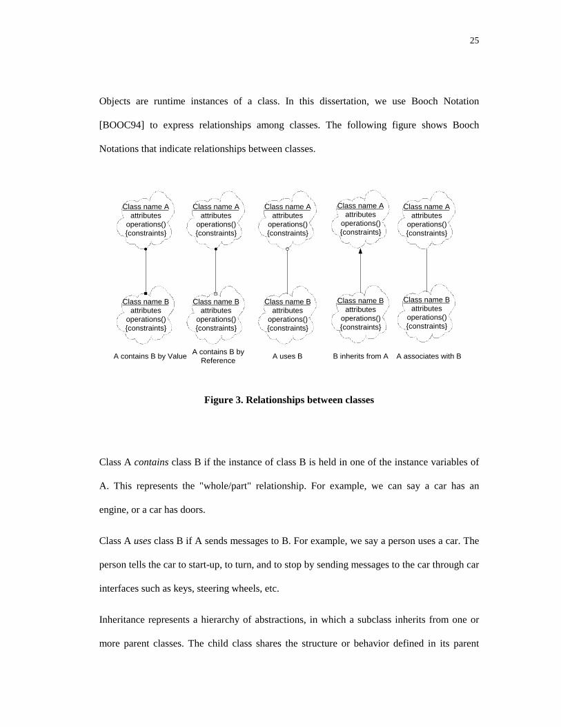
Objects are runtime instances of a class. In this dissertation, we use Booch Notation
[BOOC94] to express relationships among classes. The following figure shows Booch
Notations that indicate relationships between classes.
Class name Aattributes
operations(){constraints}
Class name Battributes
operations(){constraints}
A contains B by Value
Class name Aattributes
operations(){constraints}
Class name Battributes
operations(){constraints}
B inherits from A
Class name Aattributes
operations(){constraints}
Class name Battributes
operations(){constraints}
A associates with B
Class name Aattributes
operations(){constraints}
Class name Battributes
operations(){constraints}
A uses B
Class name Aattributes
operations(){constraints}
Class name Battributes
operations(){constraints}
A contains B byReference
Figure 3. Relationships between classes
Class A contains class B if the instance of class B is held in one of the instance variables of
A. This represents the "whole/part" relationship. For example, we can say a car has an
engine, or a car has doors.
Class A uses class B if A sends messages to B. For example, we say a person uses a car. The
person tells the car to start-up, to turn, and to stop by sending messages to the car through car
interfaces such as keys, steering wheels, etc.
Inheritance represents a hierarchy of abstractions, in which a subclass inherits from one or
more parent classes. The child class shares the structure or behavior defined in its parent

26
class. The child class differs from its parent class by modifying and adding properties. A
class can inherit the instance variables, interfaces, and instance methods of another class as if
they were defined within it. This expresses the generalization/specialization relationship. For
example, the class Sedan is a specialization of the general class Car. The class from which
another class inherits is called its parent or super-class. The class that inherits from a parent
is called a child, subclass or derived class. If a class has more than one parent, this kind of
relationship is called multiple inheritance.
Association is a semantically weak relationship. It only states there is some relationship
between the classes expressed without explicitly stating what kind of relationship. It could be
contains, use, or inheritance. This is usually used in the analysis and design phases when
some relationships among classes are still not clear or we just want to represent a general
relationship among the classes without being concerned which kind of relationship.
2.2 Graph and Dependency Definitions
This section describes the existing definitions and theories, which will be used in this thesis.
Most of the basic definitions are referenced from Loyall and Mathisen’s paper [LOYA93].
2.2.1 Graph Theory
A directed graph G is a set G = (NG, EG), where NG is a finite set of nodes, and EG ⊆ (NG ×
NG) is a finite set of edges. For each edge (u, v) ∈EG, u is the source and v is the destination.
A path in a graph G is a finite non-null sequence of nodes P = n1, n2, …nk with each ni ∈NG,
for i = 1…k and each (nj, nj+1) ∈ EG for j = 1…k-1. P is called a path from n1 to nk. k is the
length.
27
A control flow graph (CFG) is a finite, connected directed graph G = (NG, EG, Ns, Nf) where
NG is a finite set of nodes, EG ⊆ (NG × NG) is a finite set of edges, Ns ∈ NG is the start node
and Nf ∈ NG is the final node. A node in a CFG represents a statement or a basic block, i.e.,
a sequence of statements having the property that each statement in the sequence is executed
whenever the first statement is executed. An edge (ni, nj) represents a possible flow of control
between two basic blocks. The block represented by ni is executed before the basic block that
is represented by nj.
The predecessors, Pred (n), of a given node are defined as those nodes for which there is a
path to the given node. The immediate predecessors of a node ni, P (ni), are all nodes, nj, such
that (nj, ni) is in E.
The successors of n, Succ (n), are defined as those nodes for which there is a path from the
given node to them. The immediate successors of a node ni, denote S (ni), are all nodes, nj,
such that (ni, nj) is in E.
A definition of a program variable is any expression that modifies that variable. A path is
said to be definition-clear (or simply clear) with respect to a given variable if the path
contains no assignment to that variable. A definition is live at a given point in a program if
there is a definition-clear path from that point to a use of the variable in question. A
definition made at node ni is said to reach node nj if nj is a successor of node ni and there is at
least one clear path from ni to nj.
A data definition is an expression or part of an expression that modifies a data item. A data
use is an expression or that part of an expression that references a data item without
modifying it. A def-use pair is a definition and a use such that the definition may, under some

28
executions, reach the use without going through another definition. A data flow graph (DFG)
is a directed graph where the nodes and some edges are described by def-use relationships. A
data dependence exists when one statement provides a value subsequently used by another
statement either directly or through a chain of data definitions and references. Formally, A
def/use graph is a set of G = (∑, D, U), where G is the CFG for a procedure, ∑ is a finite set
of symbols, data variables, D: NG È Ρ(∑), and U: NG È P (∑). The set of symbols ∑ is the
set of identifiers and naming variables that occurs in procedure G. The functions D and U
map a node of G to the set of variables defined and used, respectively, in the statement
represented by the node. P (∑) represents the power set, i.e., the set of all sets, of ∑.
Let G = (∑, D, U) be a def/use graph and let u, v ∈ NG. Node u is directly data dependent on
node v if and only if there is a path vPu in G such that (D (v) ∩ U (u)) - D (P) ≠ 0. D (P)
denotes the union of all D (ni), where ni is a node in the sequence P. Node u is data
dependent on v if and only if there exists a sequence of nodes, n1, n2, …nk, k ≥ 2, such that u =
n1, v = nk, and ni is directly data dependent on ni+1 for i = 1, 2… k-1.
An inter-procedural control flow graph for a program is a set of graphs ς = (G1,…, Gk, C,
R), consisting of control flow graphs G1, …, Gk representing functions or methods in the
program, a set C of call edges, and a set R of return edges. An inter-procedural control flow
graph ς satisfies the following conditions:
1. There is an one-to-one mapping between C and R. Each call edge is of the form (u, niG)
∈ C and the corresponding return edge is of the form (nFGj, u) ∈ R, where u ∈ NG, for some
Gi ∈ ς and niGj and nFGj are the initial and final nodes, respectively, of some Gj ∈ ς.
29
2. ς contains two distinguished nodes: an initial node niς = niGi, and a final node nFς = nFGi,
GI ∈ ς.
An inter-procedural CFG is a set of CFGs for procedures linked together by call and return
edges. Each call edge is an edge from a node representing a procedural call to the initial node
of the CFG for the called procedure. There is a corresponding return edge for each call edge
from the final node of the called procedure’s CFG back to the node representing the
procedure call. For simplicity, we assume that there is a designated initial node and a
designated end node.
An inter-procedural def/use graph is a set Θ = (ς, ∑, D, U), where ς = (G1, …, Gk, C, R) is
an inter-procedural CFG, ∑ is a finite set of symbols and data variables, D: (NG1 ∪ … ∪
NGk) È Ρ(∑), and U: (NG1 ∪ … ∪ NGk) È P(∑).
The set ∑ is the set of identifiers and variables that occur in the set of procedures represented
by ς. The definitions and uses of actual and formal parameters at nodes represent procedure
calls.
Formally, let Gi, Gj ∈ ς be CFGs in the interprocedural def/use graph Θ. For each nc ∈ NGi,
such that (nc, niGj) ∈ C and, therefore, (nFGj, nc) ∈ R, D (nc) includes
• Formal parameters of the called procedure into which values are passed
• Actual parameters into which values are returned (including variables into which
function values are returned)
U (nc) includes

30
• Actual parameters from which values are passed
• Formal parameters of the called procedure from which values are returned.
An inter-procedural path, P, in an inter-procedural CFG = (G1, G2, …, Gk, C, R) is a
sequence of nodes n1n2…nk where ni ∈ (NG1 ∪NG2 ∪ … ∪ NGk), in = 1…k, and (nj, nj+1) ∈
(EG1 ∪EG2 ∪ … ∪ EGk ∪ C ∪ R). W satisfies the following conditions:
• P contains the sequence uniGYnfGv, where G ∈ ς, Y is a sequence of nodes, and u ≠ v, if
and only if Y contains the subsequence vniG.
• P cannot contain the sequence unFGvniG, for any G ∈ ς, v ∈ (NG1 ∪NG2 ∪ … ∪ NGk).
• P cannot contain the sequence nFGvniG, for any G ∈ ς, if and only if P = niG.
An inter-procedural u-v path P in ς represents a valid execution path from u to v in ς. Not
every path in a program’s inter-procedural CFG represents a valid execution path of the
program. This is because a procedure call in a program causes the procedure to be executed
exactly once and then returns to the point of the call. However, in the inter-procedural CFG
for a program there might be several return edges leading from the final node in a procedure.
There is often a path that enters a procedure from one node to a different node, although such
a path does not correspond to a valid execution of the program.
2.2.2 General Dependency Concepts
This section describes the general concepts related to program dependency, such as control
dependency and data dependency, ripple effect etc.
31
The transitive closure of a relationship R is the relation R+ defined by cR+d, if and only if
there is a sequence e1Re2, e2Re3,…, em-1Rem, where m >=2, c=e1, and d=en. Traceability
refers to the ability to define and trace relationships among entities such as software work
products and their components. A reachability matrix shows the objects that could be
impacted by a change to a particular object. Such a matrix also offers the distances
associated with the impact. The distance offers some insight into the relative ripple effects
associated with each object.
Data dependencies are relationships among program statements that define or use data. A
data dependence exists when a statement provides a value that is used directly or indirectly
by another statement in a program. Data def/use graphs are typical representations of these
dependencies. Data-flow analysis produces dependency information on what data goes where
in the software system.
Control dependencies are relationships among program statements that control program
execution. Control-flow analysis provides information on the logical decision points in
software and of the complexity of the control structure. Control-flow technology identifies
procedure-calling dependencies, logical decisions, and under what conditions the decision
will be taken.
A side effect is an “error or other undesirable behavior that occurs as a result of a
modification” [ARNO93]. A ripple effect is the “effect caused by making a small change to a
system which impacts many other parts of a system” [BOHN95]. Three major types of ripple
effects are coding, data, and documentation. Other important types of ripple effects defined
by researchers [BOHN95][YAUS80][YAUS87] are the following:
• Logical: influences the function or performance of the system

32
• Requirements: influences the operation of the system
• Interface: results in a change in specification of the hardware or software interface
• Environment: impacts development, maintenance, or test environments
• Management/logistics: cost, schedule, resource, contractual, deployment and training
impact
Ripple effect can be defined as the phenomenon where a change in one piece of a software
system impacts at least one other area of the same software system. A direct ripple effect
occurs when the change of one variable directly impacts the definition of another variable.
An indirect ripple effect occurs when the impacted variable in turn impacts other variables.
Stability refers to the ability of a program to resist ripple effects when it is modified. Stability
analysis differs from impact analysis in that it considers the sum of the potential ripple
effects rather than a particular ripple effect caused by a change.
The slice (sometimes called backward slice) of a program with respect to program point p
and variable x consists of all statements and predicates of the program that can impact the
value of x at point p. The slice of a program with respect to program point p and variable x
consists of a reduced program that computes the same sequence of values for x at p. That is,
at point p the behavior of the reduced program with respect to variable x is indistinguishable
from that of the original program.
A forward slice of a program with respect to a program point p and variable x consists of all
statements and predicates of the program that might be impacted by the value of x at point p.

33
3 NEW CONCEPTS/DEFINITIONS
This chapter presents the new concepts, definitions, theories and models that are developed
in this research. 3.1 defines the new concepts introduced in this research and the object-
oriented data dependency graph that are used to calculate dependencies. 3.2 discusses the
dependency calculations of different language constructions. 3.3 presents the impact models
that describe the impact analysis process.
3.1 New Definitions
This section introduces the definitions developed in this research. 3.1.1 defines the change
impact related concepts that will be used later in the algorithms. 3.1.2 defines the object-
oriented dependency graph, which is central to the research.
3.1.1 Change Impact Definitions
In structured programming, one thinks in terms of inputs, functions and outputs. In object-
oriented programming (OOP), the approach is different -- a message is passed to an object to
request an operation on the object. Objects have methods and data members; the methods
specify the allowable operations on the object’s private data, and the data members specify
the state information for the object. In this thesis, class member refers to either a method or
data member. When a class member changes, it could impact other classes through message
passing, inheritance etc.

34
3.1.1.1 Basic Types of Items
The basic component in our analysis is the class. A class is composed of member functions
and member variables. The relationships are shown in Figure 4.
Class ClassMember
Member Function Data Fields
contains
ihhe
rits
from
inherits from
Inherited from
Contain byReference
Contain by Value
Use
Figure 4. Class Components Graph
Sometimes, users want to focus on certain parts of their systems while ignoring other parts.
They can specify the classes they are interested in through a system analysis set, which
include all the classes a user is interested in analyzing. The classes that do not belong to the
system analysis set are called opaque types. In our proof-of-concept tool described later, we
view all the classes that are not compiled by the proof-of-concept system as opaque. For
example, simple types and classes in third party libraries can be treated as opaque.

35
3.1.1.2 Direct Relationship
There is a direct relationship R between class A and B (ARB) if A and B have one of the
three kinds of relationships: Containment, Use, or Inheritance. They are defined as follows:
• Containment:
Class A contains class B if B declared as a class member of A.
• Use/Reference:
There are several ways that a use/reference relationship can be formed.
1. Containment :
If class A contains class B, then class A uses Class B. If A contains B by reference, that
means that A contains a reference to B. B’s life span can be longer than A’s.
2. Classes passed in as method parameter:
If a method m of class A takes parameters P1, … Pn, we say class A uses each pi, i = 1..n,
and m is in the reference sets of each of Pi. Pi can be any class and type.
3. Classes referenced in the left hand side of assignment:
If class A or one of its members is specified in the left hand side of the assignment statement,
A or its member is defined by all the variables on the right hand side. Thus, class A (or its
member) belongs to the reference set of all those variables on the right hand side of the
equation.
4. Return type of method:
The return type of a method m is defined by m. m belongs to the reference set of this return
type. Since the parameters may not be used in the body, and their effect may not direct

36
impact the return type, we do not consider the return type to be defined by these parameter
types. If the return type is defined by a parameter, it will show up in the analysis of this
method body.
5. Variables declared in a method:
Any variable that is referenced in the method m can be considered to be used by m and can
be put into the reference set of m.
• Inheritance relationship:
Class A inherits from Class B if B is declared as a super class of A.
3.1.1.3 Indirect Relationship
A has an indirect relationship with B if there exists a path B1, B2, … , Bn, such that A R B1, B2
R B3 , … , Bn R B, expressed by AR+B.
3.1.1.4 Properties of Change Impact Dependency
A change impact dependency Α has the following properties:
Reflexive:
�&�Α�&
Class C depends on itself. It means that if C is impacted, it will impact itself.
Transitivity:
�%�Α�&�DQG�&�Α�'�⇒�%�Α�'
It means that if B impacts C and C impacts D, then B impacts D.

37
Cyclic:
There can be cycles in the impact dependency graph.
3.1.1.5 Characteristics of Impacted Member
When a member is proposed to be changed or could be impacted by another member that has
been proposed to change, it is called contaminated or impacted. The contaminated member
may or may not impact other members. According to the relationship between the impacting
member and impacted member, we classify the impact characteristics of one member to
another member into one of the four values of contaminate type: {Contaminated, Clean,
Semi-Contaminated, Semi-Clean}. If we think of impacting member as the starting node of
an edge and the impacted member as the end node, contaminate type can be thought of as the
attribute of the edge.
• Contaminated (Dirty): Start node is contaminated and it impacts the end node.
• Clean: Start node is clean and does not impact the end node.
• Semi-Contaminated (Semi-Dirty): Start node is contaminated, but it does not propagate
the contamination to the end node.
• Semi-Clean: Start node is not contaminated but it propagates the contamination to the
end node from the other source.
3.1.1.6 Change Criteria
This research requires an engineer to transfer the change requests to the change specification
that our algorithms can understand. When engineers want to specify the proposed change to

38
the system, they need to specify which parts of the system they are going to change (these
changes can be described by a set of change criteria). Our algorithms will calculate the
change impact for each criterion. The change criterion is defined as <C, CM, CT>, where C
specifies the class that is proposed to change, CM is the class member in the class C that is
proposed to change, and CT is the possible change type.
3.1.1.7 Impact Sets
FREF (x) (function reference set of x) is the set of functions that reference x; in other words,
member function m is in FREF (x) if m uses x as part of its implementation or definition.
FREF (x) represents the set of member functions that could be impacted by x if x changes.
DREF (x) (Data Member Reference Set of x) is the set of data members that use the variable
x. DREF (x) is the set of data members that can potentially be impacted by x. REF (x) is the
set of class members that reference x; REF (x) = FREF (x) ∪ DREF (x). x belongs to the
definition set of each member in REF(x). Reference set and definition set are two
complementary sets.
The Impacted Class Set (ICS) is the set of classes that could potentially be impacted by a
change. The Impacted Function Set of class C (IFS(C)) is the set of function members in C
that could potentially be impacted. The Impacted Data member Set of class C (IDS(C)) is the
set of data members in C that could potentially be impacted. The Impacted Member Set of C
(IMS(C)) is the set of class members in C that are impacted, IMS(C) = IFS(C) ∪ IDS(C).
The Semi Impacted Member Set (Semi-IMS) contains all the class members that are semi-
contaminated.

39
The Public Impacted Function Member Set (PIFS) of C is the subset of IFS that is composed
of public methods of C; PIFS(C) ⊆ IFS(C). The Public Impacted Data Member Set (PIDS) of
C is a subset of IDS that is composed of public data members of C; PIDS(C) ⊆ IDS(C). The
Public Impacted Member Set of C (PIMS(C)) is a set of public members in C that are
impacted; PIMS(C) ⊆ IMS(C). PIMS is the union of PIFS and PIDS; PIMS(C) = PIFS(C) ∪
PIDS(C). Semi Public Impacted Member Set (Semi-PIMS) is the set of semi-contaminated
public members.
3.1.1.8 Direct Impact
Member M in class B (B.M) is directly impacted (DA) by member M in B (B.M) if it
satisfies one of the following situations:
If (A contains B) and (A.M Ref B.M) and (B ∈ ICS) and (B.M ∈ IMS(B)) ⇒B.M DA A.M
If (A inherits from B) and (A.M partially-redefines B.M) and (B ∈ ICS) and
(B.M ∈ IFS (B)) ⇒ B.M DA A.M
If (A inherits from B) and (A.M inherits from B.M) and (B ∈ ICS) and (B.M ∈IFS (B)) ⇒ B.M DA A.M
If (A inherits from B) and (A.M virtual-inherits from B.M or A.M virtual-redefines B.M) and (M is the return type or in the parameter list) and (B ∈ICS) and (B.M ∈ IFS (B)) ⇒ B.M DA A.M
If (A uses B) and (A.M references B.M) and (B ∈ ICS) and (B.M ∈ IFS (B)) ⇒B.M DA A.M
3.1.1.9 Indirect Impact
If there exist a series of direct impact relationships B1 A B2, … , Bn A Bn then B1 A+ Bn.

40
B1 A B2, … , Bn A Bn ⇒ B1 A+ Bn
3.1.1.10 Object-oriented System Dependency
A dependency in a software system is, informally, a direct relationship between entities in
the system X È Y such that a programmer modifying X must be concerned about possible
side effects in Y [WILD92].
Wilde and Huitt classified dependencies as: (1) data dependencies between two variables, (2)
calling dependencies between two modules, (3) functional dependencies between a module
and the variables it computes, and (4) definitional dependencies between a variable and its
type.
Based on Wilde and Huitt’s classification on object-oriented dependencies, we come up with
the following seven dependency classifications.
1 Class-to-Class Dependencies
a) C1 is a direct super class of C2 (C2 inherits from C1)
b) C1 is a direct sub class of C2 (C1 inherits from C2)
c) C1 is an ancestor class of C2 (C2 indirectly inherits from C1)
d) C1 uses C2 (C1 references C2, include direct reference and indirect reference)
e) C1 contains C2
I. C1 contains C2 by value
II. C1 contains C2 by reference
2 Class to Method
a) Method M returns object of Class C
b) C implements method M
3. Class to Variable

41
a) V is an instance of Class C
c) V is a class variable of C
d) V is an instance variable of C
e) V is defined by class C
4. Method to Variable
a) V is a parameter for method M
b) V is a local variable in method M
c) V is imported by M (i.e. is a non-local variable used in M)
d) V is defined by M
5. Method to Method
a) Method M1 invokes method M2
b) Method M1 overrides M2
3.1.1.11 Types of Changes and Their Relationship
The section categorizes the different kinds of changes and their relationships. The changes
can be divided into syntactic changes and semantic changes. We focus on the syntactic
change in this research. The hierarchy of syntactic change is:
1 System level change
a) Add super class
b) Delete super class
c) Add sub class
d) Delete sub class
e) Delete an object pointer
f) Delete an object reference
g) Add an aggregated class
h) Delete an aggregated class
i) Change inheritance type

42
I. Change from public inheritance to private inheritance
II. Change from private inheritance to public inheritance
2 Class level change
a) Add member
b) Delete member
c) Define/Redefine member
d) Change member
I. Change member access scope
1) Change from public to private
2) Change from public to protected
3) Change from protected to public
4) Change from protected to private
5) Change from private to public
6) Change from private to protected
II. Change method
1) protocol change
• name change
• parameter change
• return type change
III. Change Data member
1) Add data declarations
(a) Delete data declarations
(b) Add data definitions
(c) Delete data definitions
(d) Change data declaration
• Change data type
• Change data name
(e) Change data definition

43
IV. Function implementation change
e) Add/delete an external data use
f) Add/delete an external data update
g) Add/delete/change a method call
h) Add/delete a sequential segment
i) Add/delete/change a branch/loop
j) Change a control sequence
k) Add/delete/change local data
l) Change a sequence segment
3.1.2 Object-Oriented Data Dependency Graph Theory
Traditionally, dependency analysis has been performed with so-called data dependency
graphs, unfortunately misnamed since the nodes of the graph really represent statements of
the program while the edges represent dependencies between statements. Thus, the graph
makes no reference to data. Data dependency graphs normally represent every statement of
the program with all of its dependencies [MOSE90].
In object-oriented designs, the emphasis is on what the program does to, data, instead of what
the program does. In order to put the emphasis on the data and the data relationships, we
introduce the Object-Oriented Data Dependency Graph (OODDG) to describe data
relationships in object-oriented systems. In an OODDG, the nodes represent data items, such
as classes, class members, variables and constants. The edges represent dependencies among
these data items.
Following are four definitions of graphs that describe object-oriented software.
1) Definition (Intra-Method Data Dependency Graph)

44
Intra-Method Data Dependency Graph (Intra-Method DDG) is a directed graph G = (N, E,
R, W). N is a set of nodes that represent symbols that include all the members of the
method’s container class, local and global variables, and global functions, parameters and
return variables of this method. E ⊆ (N × N) is the set of edges that describe the
dependencies between nodes. R is an attribute on E that assigns one of the contaminated type
values (Clean, Semi-Clean, Contaminated and Semi-Contaminated) to each edge. W, which
quantitatively represents the degree of the impact from the start node to end node, is a
relation on E that assigns a numeric weight to each edge.
An intra-method DDG is used to describe the data dependency among data elements inside a
method or function. It describes the types of the dependencies, and degree of impact among
these data elements. R on the edge describes the impact contaminate type of the starting node
to the end node. This graph can be used to calculate the impacted elements inside a method
or function when certain data elements in the function are changed.
2) Definition (Inter-Method Data Dependency Graph)
An inter-method data dependency graph (Inter-Method DDG) is a set of 4-tuples Θ = (Gi, ∑
vi, Ri, Wi), i = 1..k, where k is the number of intra-method DDGs in Θ. Gi is an Intra-Method
DDG and Ni is the node set of graph Gi. ∑ represents all the nodes in Θ, ∑ = N1 ∪ N2 ∪ …
∪ Nk. ∑vi represents the nodes in ∑ that are visible to Gi. Relation Ri: Ni È Ρ(∑vi) represents
a set of edges among the sub-graphs that maps a node in Ni to a set of nodes in P (∑vi). P (∑
vi) represents the power set, i.e., the set of all sets, of ∑vi. Wi is an attribute of the relation Ri
that assigns a numeric weight to Ri.
45
The Inter-Method Data Dependency Graph (Inter-Method DDG) describes the data
dependency relationships among different methods and functions. Ni is the set of all the
eligible variables in Gi. ∑vi is the set of symbols in the whole inter-graph that are accessible
to Gi. The accessibility depends on the relationships of those symbols to Gi. For example, all
global variables and global functions are accessible, the public and protected members of
super classes are accessible, and all the public members of any class inside the system are
accessible. This graph can be used to calculate the change dependency across the boundaries
of different methods.
3) Definition (Class Impact Weight Factor)
Class Impact Weight Factor is a numeric value used to express the impact level of one class
to another. It considers the factors of contaminate type and relationships among impacted
classes.
Contaminate Type (Ct) describes the characteristics of the impact from one element to
another. Ct can be assigned to one of the four values: Clean, Semi-Contaminated, Semi-Clean,
and Contaminated. Clean is assigned the value 0, because it means the start node of the edge
has no impact on the end node. Semi-Contaminated is assigned the value 1, it means even
though it is contaminated it will not continue to propagate the contamination. Semi-Clean
means that even though the node is not impacted, it will propagate the contamination from its
referenced set to its referencing set; it is assigned the value of 2. Contaminated means the
start node is contaminated and it will propagate the contamination to elements that reference
it. Contaminated is assigned the highest value 3. These values are summarized in Table 1.

46
Table 1 Impact Power of Contaminate Type Values
Contaminate Type Impact Power (Value)
Clean 0
Semi-Clean 1
Semi-Contaminated 2
Contaminated 3
Object Relationship Type (Cr) describes the level of the impact of relationships among
objects. Cr can be assigned to one of the following values:
Table 2 Object Relationship Type Values
Object Relationship Impact Power (Value)
Use 1
Containment 2
Inheritance 4
Inheritance is assigned to the greatest impact power, with containment relationship in the
middle and use relationship the least, because we think the impact power of inheritance is
greater than the impact power of containment, and it is greater than the impact power of use.
Inheritance is considered to have the highest impact power because super class defines sub-
classes’ behavior. Any changes in the public and protected levels of the super class will
impact its sub classes. A containment relationship implies the use relationship with
additional constraints, like the life span of the contained object may be the same as that of
the container class. The contained classes’ constructors and destructors are always called by
the container class. So the impact power of containment is considered to be greater than that
of the use relationship. Since the coupling between inheritance is much higher, its impact
power is assigned a higher value than that of containment and use.

47
The class impact weight W is defined as
W = Ct + Cr
4) Definition (Object-Oriented System Dependency Graph)
Object-Oriented System Dependency Graph (OOSDG) is a graph Θ= {N, E, R, C, W}. N is
the set of nodes representing the classes. E = (N×N) is the set of edges connecting nodes that
represent the dependency relationships between the nodes. R, C and W are attributes of
edges. R is the edge label that assigns the relationships among object classes (inheritance,
containment, use) to each edge. C is the edge attribute that assigns the contaminate type
(Clean, Semi-Clean, Contaminated, Semi-Contaminated) to each edge. W is the class impact
weight factor that assigns the numeric class impact factor to each edge.
This graph describes the class level dependencies in object-oriented systems. It captures the
types of relationships among classes, the types of impacts and the numeric impact levels
between classes. It is used to calculate the change impact at the system level.
3.2 Calculate Reference Dependency
This section describes how to extract reference relationships among data items from different
types of statements. We describe the technique for primitive statement, if-else statements,
looping statements and switch statement. The method that contains the statements is defined
as the container method of those statements.
3.2.1 Primitive Statements
There are two kinds of primitive statements to consider: simple assignment and message
passing (procedure call).
48
• Assignment:
Variable x = Expression;
Variable x depends on all the variables, constants, objects and their members on the right
hand side of assignment. Those elements that are referenced in the expression are considered
to be belong to the definition set of x. x belongs to the reference set of each of those
elements.
• For message passing (procedure call):
Variable x = object.method (P1, P2, …, Pn);
Both variable x and the method that contains this variable depend on the object on the right
hand side and all its parameters. So x and the container method of this statement belong to
the referencing set of object and Pi, i = 1..n.
3.2.2 Conditionals and Loops
• If-else statement
If (b) then statemen1 else statement2;
The container method of this statement references all the elements in b and in statement1 and
statement2. Since the value of b decides the execution path of the if-else statement, the
referencing set of all the data elements in b includes all the data elements in statement1 and
statement2.
• While/Repeat statement
While (b) then statements;
Repeat statements until (b)

49
The container method of the while and repeat statement references all the data elements in b
and data elements in the statements of the looping block. Since the value of b decides
whether statements in the loop are executed and how many times they are executed, the
referencing sets of all the data elements in b include all the data elements in the loop.
• Switch statement
switch (b)
{
case CONST1: statement1; break;
case CONST2: statement2; break;
…
case CONST n: statement n; break;
default:
statement 0;
}
The container method of the switch statement references all the data elements in b and in
statements of different switch branches. Since the value of b decides which branch to
execute, the referencing sets of all the data elements in b include all the data elements in the
statements of all branches.
3.2.3 Method Processing and Parameter Passing
Method parameters and local variables play an important role in change propagation. When a
method is called, the actual parameter is used to substitute the formal parameter described in
the prototype.
Method_name@Q1,…Qk È R is used to express the signature of method. Q1 to Qk will be
substituted by the actual parameters A1 to Ak. If the actual parameters are changed, they will
impact other members if they are used in the body of the method. So Q1 to Qk are considered
to be the referencing set of A1 to Ak.
Ai ∈ ReferencingSet(Qi)

50
Any variables and methods that are used in the body of the method belong to the referencing
set of the current method. The formal parameters are not considered to be part of the
referencing set of the method unless it is actually used in the method body.
The life span of the local variable is limited to the body of the method or block. Within the
block, it can propagate the change from one class member to another one. For example,
member m1 of class C is impacted, there is a local variable v defined by m1, and there is
another member m2 defined by v. C::m1’s change will impact C::m2 because of v. Just as
with formal parameters, the declared local variables will not automatically belong to the
referencing set of the current method unless they are actually used, referenced or defined in
the body.
3.2.4 Processing of Pointers and References
When the parameter passing is by value like C++, any changes to the formal parameter (Q)
inside the method body will not propagate back to the actual parameter (A) being passed in.
So Q belongs to the reference set of actual parameter A, but A is not considered to belong to
the reference set of Q.
When the parameter passing is by reference, or when the parameter passing is by value but
the parameter is passed as a pointer or reference, changes inside the method can be
propagated back to the actual parameter. So when an object is passed as a pointer or
reference, the formal parameter Q is considered to be the reference member of the actual
parameter A, and the actual parameter A is considered to be the reference set member of the
formal parameter Q.
In summary, when parameters are passed by value:
51
Ai ∈ ReferencingSet(Qi)
When parameters are passed by reference or as pointers:
Ai ∈ ReferencingSet(Qi) ∩ Qi ∈ ReferencingSet(Ai)
Similarly, when a pointer is assigned to the address of another object, the dependency path is
bi-directional. It means:
P = &Object1;
P ∈ ReferencingSet(Object1) ∩ Object1 ∈ ReferencingSet(P)
When P = &Object2, P and Object2 set up the bi-directional dependency while the bi-
directional dependency between the P and Object1 is broken.
P ∈ ReferencingSet(Object2) ∩ Object2 ∈ ReferencingSet(P) ∩ P ∉ReferencingSet(Object1) ∩ Object1 ∉ ReferencingSet(P)
The operations are:
ReferencingSet(Object1) = ReferencingSet(Object1) ∪ P
ReferencingSet(P) = ReferencingSet(P) ∪ Object1
ReferencingSet(Object2) = ReferencingSet(Object2) - P
ReferencingSet(P) = ReferencingSet(P) - Object2
3.2.5 Implementation Change
When the implementation details of a method/function are changed, but the interface and
semantics remain the same, the change will not propagate and impact other classes and class
members in the system. This type of change is called Semi-Clean.
3.3 Impact Models
We divide the types of impact into two dimensions: static and dynamic impact and syntactic
and semantic impact.

52
Static Dynamic
Semantic
Syntactic
Figure 5. Impact Model Dimension View
The syntactic impact is calculated purely by information extracted from the source code.
This information includes the data flow, the control flow and the calling hierarchy. In
addition to syntactic knowledge, semantic knowledge is necessary to find the probable ripple
effects.
Semantic knowledge consists of programming knowledge and domain knowledge. Semantic
knowledge is more difficult to derive and more difficult to verify.
In software testing, debugging and maintenance, one is often interested in the following
question:
When can a change in the semantics of a program statement impact the execution behavior
of another statement?
This question is undecidable in general [PODG90]. Dependence analysis, like data flow
analysis, avoids problems of undecidability by trading precision for decidability. During
dependence analysis, programs are represented by def/use graphs, which contain limited
semantic information but are easily analyzed. Dependence analysis allows semantic
questions to be answered “approximately,” because a program’s dependencies partially
determine its semantic properties. See 0 for more detailed ideas on this subject.
53
Static impact is calculated according to static information obtained at compile time. The
calculated set will be bigger than the set calculated by run time information. For example, a
class in the method’s signature can be substituted by any of its subclasses at run time, but
which subclass cannot be known until run time. We have to approximate the result to count
all its subclasses’ effect.
While dynamic binding provides flexibility for object-oriented languages, it may also
greatly complicate the tracing of dependencies. When a message is sent to a variable holding
an object, the actual method implementation that will be called depends on the object’s class.
Since different implementations will establish different dependencies, static analysis will not
always be able to precisely identify the dependencies in the program.
There are four possible approaches to the problem of dynamic binding:
1. Perform a “worst case” analysis in which the possible effects of the message are taken to
be the union over all the relationships set up by any of the method implementations. This
method might be adequate for C++ programs that use the virtual directive sparingly; it will
be less satisfactory for systems such as Java in which every method is polymorphic.
2. Use dynamic analysis, in which the program is run for several test cases with probes
inserted to detect the real classes of the objects of interest. The problem is that the test cases
may not detect all the behaviors that the program is capable of exhibiting, and thus incorrect
conclusions may be drawn.
3. Allow human input to identify the possible classes of objects. Users can limit the scope
of a query to obtain much more focused results. In our research, we allow users to specify a
list of components that they are not interested in to cut down the scope.

54
4. It may be possible to analyze each message to reduce greatly the number of possible
classes for each object.
Dynamic impact is calculated by executing the program. Since we have more accurate
information at run time, such as what subclass is substituted for what base class, the
calculated sets are smaller. But the results are only related to their corresponding input cases.
The following graph shows the relations among the different sets. Max impact set is defined
as the full program. The max impact set contains the static impact set. The static impact set
contains the dynamic impact set. The dynamic impact set contains the minimum impact set.
Max Impact Set(Whole System)
Static Impact Set
Dynamic Impact Set
Min Impact Set
Figure 6. Impact Set Venn Diagram
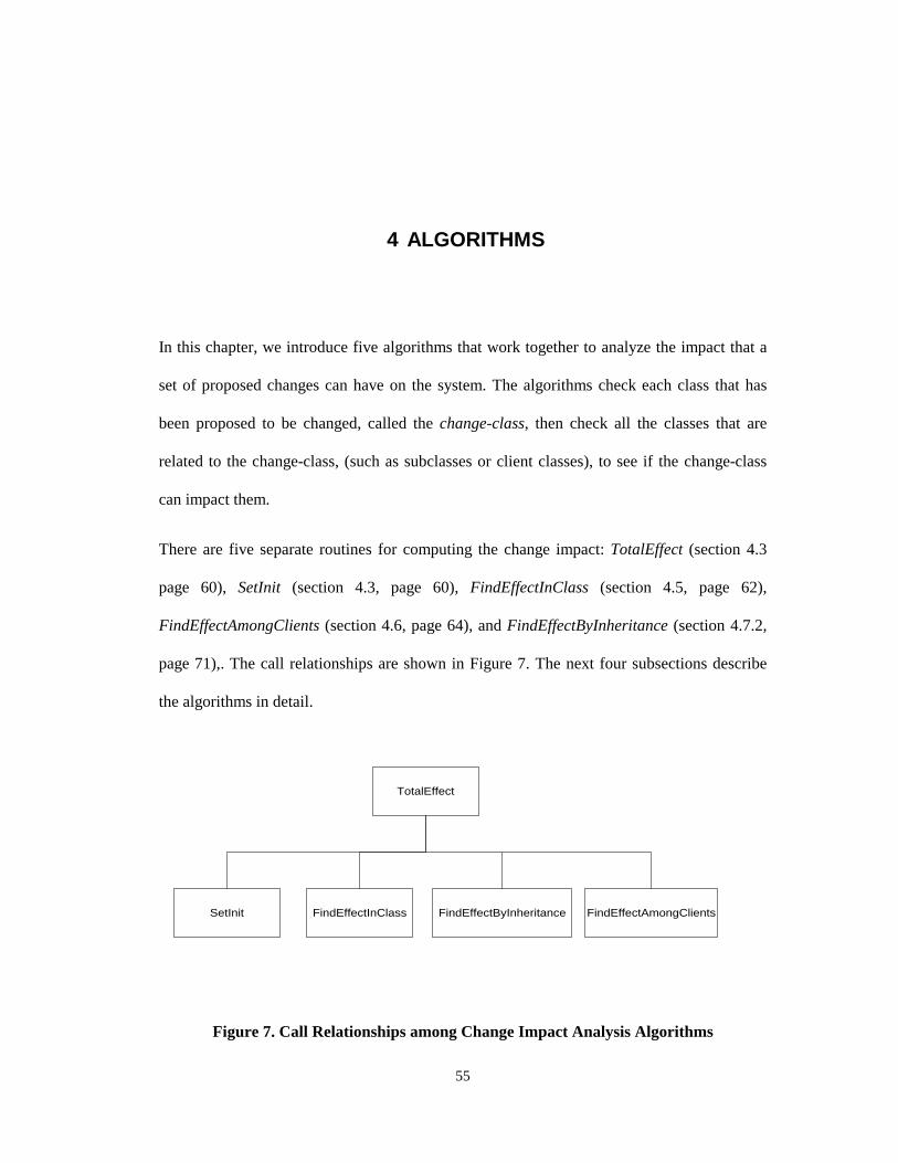
55
4 ALGORITHMS
In this chapter, we introduce five algorithms that work together to analyze the impact that a
set of proposed changes can have on the system. The algorithms check each class that has
been proposed to be changed, called the change-class, then check all the classes that are
related to the change-class, (such as subclasses or client classes), to see if the change-class
can impact them.
There are five separate routines for computing the change impact: TotalEffect (section 4.3
page 60), SetInit (section 4.3, page 60), FindEffectInClass (section 4.5, page 62),
FindEffectAmongClients (section 4.6, page 64), and FindEffectByInheritance (section 4.7.2,
page 71),. The call relationships are shown in Figure 7. The next four subsections describe
the algorithms in detail.
TotalEffect
SetInit FindEffectInClass FindEffectByInheritance FindEffectAmongClients
Figure 7. Call Relationships among Change Impact Analysis Algorithms
56
This research emphasizes the class and method level, even though statement level
information is extracted from the source. In general, object-oriented programs tend to be
structured rather differently than conventional programs. For many tasks, very short methods
may be written that simply “pass through” a message to another method with very little
processing. Thus a system may consist of a large number of very small modules rather than a
relatively smaller number of larger ones. So object and message level output is more useful
in object-oriented development. The method level dependencies indicated by the tool are
closer to the software developer/maintainer’s view of a system than statement or variable
level dependencies. Another reason to emphasize the object and its members is that the
traditional structural analyses are mainly focused on the statement level. There is already a
fair amount of research in that area while not enough work focuses on the specific
characteristics of object-oriented software. If we need to extend our work to the statement
level, the only thing we need to do is integrate our results with the traditional CFG and DFG
techniques. In other words, apply the CFG and DFG techniques to the statements inside the
methods of classes, or global functions. After all, class methods are simply functions; what
has been said about functions applies to method as well.
4.1 Algorithms Description
One important aspect of impact analysis is how to specify a change that could be understood
by our algorithms. As defined in Chapter 3, a change is represented as a triplet <C, CM, CT>,
where C specifies the change-class, CM is C’s class member; and CT is the possible change
type. When engineers want to specify the proposed change, they need to specify which parts
of the system they are going to change by specifying a set of change criteria.

57
After change criteria have been specified, our algorithms calculate the change impact for
each criterion. Our tool converts the control flow graphs (CFGs) and data flow graphs
(DFGs) of the examined functions of the change-class to object-oriented data dependency
graphs (OODDGs). The algorithms will find all member functions and data members in the
examined software that could be impacted. According to the specified change criteria, the
algorithms first calculate the impact that changes could have inside the class. After
calculating all the impacted members in the impacted class, the algorithms examine the
relationships among the objects in the system. According to the characteristics of inheritance
and encapsulation, the algorithms calculate the change effects by following different types of
relationships in the system. The algorithms continue until no new impacted class or impacted
class member could be found. The result is the transitive closure of the change criteria.
Semantic knowledge of the analyzed system combined with syntax knowledge could be used
to make the change impact analysis more accurate. We categorize possible changes to an
object-oriented system and give each type of change an attribute according to how the
change can impact the rest of the system. The algorithms are optimized according to the
change categories. We have also developed an object-oriented metrics system to measure the
change impact. The algorithms are described in detail in our paper [LIOF96] and the
technical report [LIOF96a]. The technical report [LIOF96b] expresses the algorithms in
datalog rules.
A Typical Use of the Impact System
Assume that we want to calculate the impact of a set of change criteria <C, CM, CT>. First,
the Impacted Class Set (ICS) is initialized to the set of change-classes, and initializes the
impacted function member set of Ci (IFS (Ci)) and impacted data member set of Ci (IDS (Ci))
58
of each class in the ICS. For example, if class C is in the ICS, its data member f0 and method
m0 have been proposed to be changed, we have:
Step 1
ICS = {set of classes proposed to change}
IFS (c) = {m0}
IDS (c) = {f0}
Assume that at step n-1, IFSn-1(C) contains all the impacted function members in C, and IDSn-
1(C) contains all the impacted data members in C:
Step n
IFSn(c) = {m ∈ C | ∃ x∃ C’(m ∈ FREF (x) ∧ x ∈ IDS n-1 (c’))}
∪ {m ∈ C | ∃ f ∃ C’(m ∈ FREF (f) ∧ f ∈ IFS n-1 (C’))}
The above formula means that IFS(C) at step n is the union of two sets. The first set is
composed of all the function member m in C such that there is at least one variable x for
which m belongs to the reference set of x and x belongs to the IDS set at step n-1. The
second set is composed of all the function members, m, such that at least one function
member n exists for which m belongs to the reference set of n and n belongs to the impacted
function set at step n-1.
In other words, the above formula means the IFS of C contains all the function members that
reference any data members in IDSn-1, plus all the function members that reference any other
function members in IFSn-1.
Step n
IDS n(c) = {d ∈ C | ∃ x∃ C’(m ∈ DREF (x) ∧ x ∈ IDS n-1 (c’))}
∪ {d ∈ C | ∃ f ∃ C’(m ∈ DREF (f) ∧ f ∈ IFS n-1 (C’))}
The above formula means that IDS(C) at step n is the union of two data member sets. The
first set is composed of all the data members d in C such that there is at least one variable x

59
for which d belongs to the reference set of x and x belongs to the impacted data member set
calculated at step n-1. The second set is composed of all the data members, d, such that there
is at least one function member f for which d belongs to the reference set of f and f belongs
to the impacted function set of step n-1.
In other words, the above formula means the IDS of C contains all the data members that are
defined by any field in IDSn-1, plus all the data members that are defined by any member
functions in IFSn-1.
4.2 Inputs and Outputs of the Algorithms
Inputs:
• The legacy system
• The change criteria that users specify
Outputs:
• ICS, and IFS, IDS of each class in ICS
• A set of metrics that measure the impact
ICS
ImpactedMethods
ImpactedData Fields
ImpactedClasses
1
n
n1 ImpactedMembers
Inherited from
Contain by Reference
Contain by Value
Use
Figure 8. Impact Set Component Graph

60
The output of the algorithms is the Impacted Class Set (ICS), which contains a set of
impacted classes. Each class in the ICS contains one or more impacted class members. The
class members can be data members or function members. Users can also view a set of
object-oriented change impact metrics values developed in this research to measure the
change impact quantitatively.
4.3 Total Effect
The algorithm TotalEffect is the main algorithm that glues the other algorithms together.
TotalEffect initializes the ICS and the IFS and IDS of each class in ICS using SetInit ().
SetInit () also marks each class in the ICS as unchecked. TotalEffect picks an unchecked
class from the system, marks it checked, then calls the different subroutines to analyze the
impact caused by the different relationships among classes. FindEffectInClass(C) analyzes
the impact effects within the class, FindEffectByInheritance(C) analyzes the effects
following the inheritance hierarchy in the system, and FindEffectAmongClients(C) analyzes
the effects in the system according to encapsulation and the use (reference) relationship.
During execution, if the IFS or IDS of any checked class increases, the set is marked as
unchecked again for further examination.
Algorithm TotalEffect ()Input: The set of changed classes and their changed methods and data members.Output: The impacted classes and their methods, data members in the system.BEGIN SetInit ();
WHILE (ICS ≠ φ )
BEGIN Pick one class from the ICS and mark it checked FindEffectInClass(C) FindEffectByInheritance(C) FindEffectAmongClients(C) ENDWHILE END TotalEffect
Figure 9. Total Effect Pseudo Code

61
• Initialization (SetInit)
SetInit initializes the ICS, IFS(C), and IDS(C) according to the change criteria that the user
specifies. The ICS is set to the change-classes in the criteria; and IFS(C) is set to the function
members in C that have been proposed to change. Similarly, IDS(C) is initialized to the data
members of C that have been proposed to change
Algorithm SetInit ()
BEGIN
ICS = {the set of changed classes}
Mark each class in the ICS unchecked
FOR each class in the ICS
BEGIN
IFS[Ci] = {the set of function members changed in Ci }
IDS[Ci] = {the set of data members changed in Ci }
ENDFOR
END SetInit
Figure 10. Initialization Pseudo Code
4.4 Encapsulation
In traditional programming, the basic unit is a procedure. In object-oriented programming,
methods or member functions are the actions that can be performed on objects. They
manipulate and express the state of the object, define the interface to other classes and in
many ways are not logically independent.
For each class C, IFS[C] contains all the function members that could be impacted by the
specified changes. IDS[C] holds all the data members that could be impacted by the specified
changes. Since the only way to observe the state of an object or operate on an object is
through its public members, an object’s clients can only be directly impacted by the public
members. PIFS[C] contains all the public function members that could be impacted. PIDS[C]
62
holds all the public data members that could be impacted. PIFS[C] ⊆ IFS[C] and PIDS[C] ⊆
IDS[C].
Encapsulation is a way to separate the implementation of a data object from its specification.
An object does this by managing its own resources and limiting the visibility of what others
should know. An object publishes a public interface that defines how other objects or
applications can interact with it. An object also has a private component that implements the
methods. The object’s implementation is encapsulated -- that is, hidden from the public view.
In the presence of encapsulation, the only way to observe the state of an object is through its
interface (public methods). The class hides the properties of its instances to conceal the data
structure and the details of implementation. All the features of an object are usually hidden,
such that the only way the state can be examined or modified is by invoking part of the
interface formed by its public properties. The interface is a basis for a protocol that objects
use to communicate with each other by requesting an object to invoke one of its operations.
Class members inside the class can see all the properties within the class, so there is no scope
restriction in FindEffectInClass. Because of encapsulation, in FindEffectAmongClients,
methods or data members in a client class can only be impacted by public members of the
server class, and in FindEffectByInheritance, methods or data members in a subclass can
only be impacted by public or protected members of the parent class.
4.5 The Containment Relationship: FindEffectInClass
FindEffectInClass (C) calculates change impacts inside a class. It examines each class
member m (including function member and data member) in C that is not in the impacted
member set (IMS). If m references any methods in IFS (FREF (m) ∩ IFS (C) ≠ φ) or m

63
references any data members in IDS (DREF (m) ∩ IDS (C) ≠ φ); m could be impacted by the
changes in IFS and IDS. So it will be added to IMS and to PIMS if m is public.
This sounds reasonable, but unfortunately this calculation is not sufficient. Assume a class
has methods m1, m2, m3, m4, and m5, m1 and m2 are in IMS. m3 references m5 and m5
references m2, so m3 references m2 indirectly. Since m2 ∈ IMS, m3 should belong to IMS.
But when the algorithm is checking m3, m5 has not been checked yet, and m3 could not find
any reference in IMS set, so the algorithm thinks it is clean and fails to put it in IMS.
FindEffectInClass solves this problem by calculating the transitive closure of the impacted
member set. FindEffectInClass, a breadth-first search algorithm based on the δ-wavefront
algorithm [QUAD91], starts from the initial impacted class members, and iterates to find all
of the members that could be impacted by the members in IFS and IDS. In other words, it
iterates to find all of the nodes reachable from these initial nodes.
In this section, we use IMS(C) to specify the set that contains the class members of C
(IMS[C] = IFS[C] + IDS[C]). Current_IMS is used to specify the nodes found in each
iteration. IMS accumulates nodes found during different iterations of the algorithm. We
could accept the following simple approach. At the beginning of the kth iteration,
Current_IMS holds the impacted class members that could be impacted by the impacted
member in the kth iteration; the generated node is one arc away from those nodes in IMS (or
k arcs away from the initial nodes). The newly generated nodes, which form the new
Current_IMS, are put into the IMS. The iteration process continues until IMS does not
change from one iteration to another. This simple approach suffers a serious drawback when
dealing with a graph that is not a list or tree. This is because this version of algorithm has no
memory. During an iteration, it may process some nodes in the base graph, even through
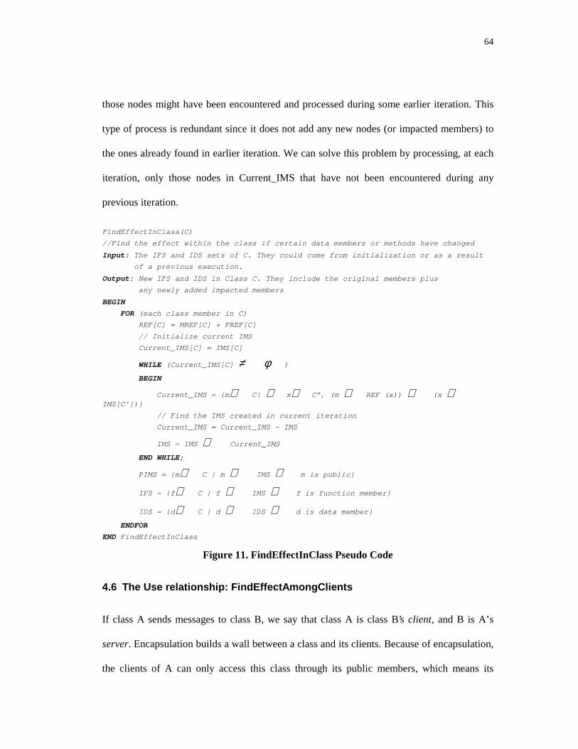
64
those nodes might have been encountered and processed during some earlier iteration. This
type of process is redundant since it does not add any new nodes (or impacted members) to
the ones already found in earlier iteration. We can solve this problem by processing, at each
iteration, only those nodes in Current_IMS that have not been encountered during any
previous iteration.
FindEffectInClass(C)
//Find the effect within the class if certain data members or methods have changed
Input: The IFS and IDS sets of C. They could come from initialization or as a result
of a previous execution.
Output: New IFS and IDS in Class C. They include the original members plus
any newly added impacted members
BEGIN
FOR (each class member in C)
REF[C] = MREF[C] + FREF[C]
// Initialize current IMS
Current_IMS[C] = IMS[C]
WHILE (Current_IMS[C] ≠ φ )
BEGIN
Current_IMS = {m∈ C| ∃ x∃ C”, (m ∈ REF (x)) ∧ (x ∈IMS[C’])}
// Find the IMS created in current iteration
Current_IMS = Current_IMS - IMS
IMS = IMS ∪ Current_IMS
END WHILE;
PIMS = {m ∈ C | m ∈ IMS ∧ m is public}
IFS = {f ∈ C | f ∈ IMS ∧ f is function member}
IDS = {d ∈ C | d ∈ IDS ∧ d is data member}
ENDFOR
END FindEffectInClass
Figure 11. FindEffectInClass Pseudo Code
4.6 The Use relationship: FindEffectAmongClients
If class A sends messages to class B, we say that class A is class B’s client, and B is A’s
server. Encapsulation builds a wall between a class and its clients. Because of encapsulation,
the clients of A can only access this class through its public members, which means its
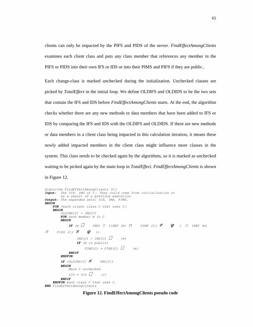
65
clients can only be impacted by the PIFS and PIDS of the server. FindEffectAmongClients
examines each client class and puts any class member that references any member in the
PIFS or PIDS into their own IFS or IDS or into their PIMS and PIFS if they are public..
Each change-class is marked unchecked during the initialization. Unchecked classes are
picked by TotalEffect in the initial loop. We define OLDIFS and OLDIDS to be the two sets
that contain the IFS and IDS before FindEffectAmongClients starts. At the end, the algorithm
checks whether there are any new methods or data members that have been added to IFS or
IDS by comparing the IFS and IDS with the OLDIFS and OLDIDS. If there are new methods
or data members in a client class being impacted in this calculation iteration, it means these
newly added impacted members in the client class might influence more classes in the
system. This class needs to be checked again by the algorithms, so it is marked as unchecked
waiting to be picked again by the main loop in TotalEffect. FindEffectAmongClients is shown
in Figure 12.
Algorithm FindEffectAmongClients (C0)Input: The ICS, IMS of C0. They could come from initialization or as a result of a previous execution.Output: The expanded sets: ICS, IMS, PIMS.BEGIN FOR (each client class C that uses C0) BEGIN OLDIMS[C] = IMS[C] FOR each member m in C BEGIN
IF (m ∉ IMS) ∧ ((REF (m) ∩ PIMS (C0) ≠ φ ) ∨ (REF (m)
∩ PIDS (C0) ≠ φ ))
IMS(C) = IMS(C) ∪ {m} IF (m is public)
PIMS(C) = PIMS(C) ∪ {m} ENDIF ENDFOR
IF (OLDIMS[C] ≠ IMS[C]) BEGIN Mark C unchecked
ICS = ICS ∪ {C} ENDIF ENDFOR each class C that uses C0
END FindEffectAmongClients
Figure 12. FindEffectAmongClients pseudo code
66
4.7 The Inheritance Relationship: FindEffectByInheritance
Inheritance is the abstraction mechanism that allows developers to create new child classes --
known as subclasses or derived classes -- from existing parent classes. Different languages
accept different inheritance schemes (strict inheritance, subtyping, subclassing, etc.). Strict
inheritance is the simplest inheritance scheme; it keeps the exact behavior of its parent. The
inherited properties cannot be modified, and the derived class can only be redefined by
adding new properties. Subtyping is the most commonly used scheme. Subtyping allows the
inherited properties to be redefined when the parent’s operation is not appropriate for the
subclass. In subclassing, the derived class is not considered to be a specialization of the base
class, but a completely new abstraction that bases part of its behavior on part of another
class. This scheme is also called implementation inheritance. The derived class can therefore
choose not to inherit all the properties of its parent (sometimes called suppression). In this
research, we assume the language uses subtyping (as in C++ and Java). The algorithm can be
easily modified for other inheritance schemes.
4.7.1 Properties of Inheritance
Inheritance represents a hierarchy of abstractions, in which a subclass inherits from one or
more super classes. The child class shares the structure or behavior defined in its parent
class. The child class can express differences with its parent class by modifying and adding
properties. If the class c inherits from p, we express it as c::p. If the object is an instance of
class c, we express it as o:c. The signature of the method can be expressed as
Method_name@Q1, … , Qk È T, where Q1, … , Qk are parameters and T is the return type.
Kifer and Lausen [KIFE95] express inheritance in their frame logic:

67
Inheritance reflectivity:
I È p::p
Inheritance reflectivity says p can be its own parent.
Inheritance transitivity:
If I È p::q and IÈq::r then IÈp::r
Inheritance transitivity says that if p is a subclass of q and q is a subclass of r then p is a
subclass of r.
Inheritance acyclicity:
If I È p::q and I È q::p then I È p = q
Inheritance acyclicity says there is no cycle in the inheritance relationship except the
inheritance relationship among itself. In other words, if two classes inherit from each other,
they are the same class.
Inheritance Inclusion:
If I Èp:q and IÈ q::r then I È p : r
Inheritance Inclusion says that if p is an instance of q and q is a subclass of r then p is an
instance of r also.
Because of the inheritance, the signature of the method can have these properties:
Type inheritance:
If I È p [method@q1, … , q n È s ] and I È r::p then I È r[ method@q 1, … , q n È s ]
Input restriction:

68
If I È p [method@q1, … , qi, … , qn È s ] and I È q i
’ ::qi then I È [ mehtod@q1, … ,qi
’ , …, q n È s ]
Output restriction:
If I È p [method@ q 1, … , qn È s ] and I È r::s then I È [ method@q 1, … , q n È r ]
Type inheritance tells us that if r is a subclass of p, then the method r inherits the signature of
p’s method. But this does not mean r cannot modify the semantics of the method. R can
completely inherit the behavior of p, partially overwrite it or completely overwrite the
original method. Input restriction says if qi’ is a subclass of qi, then qi’ can appear at any
place where qi can in the signature. Output restriction says that if r is a subclass of s then the
method that returns s can return r as well.
Inheritance can be thought of as an incremental modification technique that combines a
parent P with a modifier M to get a resulting class R, R=P⊕M. The subclass designer
specifies the modifier, which may contain various types of attributes that alter the parent
class to get the resulting subclass. Although M transforms P into a new class R, M does not
totally constrain R. We must also consider the inheritance relation since it determines the
effects of composing the attributes of P and M and mapping them into R. The inheritance
relation determines the visibility, availability and format of P's attributes in R. Since
inheritance is deterministic, rules can be constructed to identify the availability and visibility
of each attribute.
When a subclass redefines one of its parent's methods, it can either totally replace the method
or simply expand its functionality. The impact of the parent's method on this subclass will be
different depending on how the subclass expands the parent's method. If the subclass totally
re-implements its parent's method, the change in the parent's method will not impact the

69
subclass. If the subclass expands its parent’s service based on the service the parent’s method
provides, any change in the parent’s method could impact this subclass. Harrold and
McGregor [HARR92] proposed an attribute classification to describe the different types of
attributes according to their inheritance relationship. We extend their attributes classification
by splitting the redefine and virtual redefine into extended redefine, total redefine, virtual-
extended redefine, and virtual-total-redefine. As a result, methods in subclasses are divided
into the following extended categories:
• New attribute: A is an attribute that is defined in M but not in P, or A is a member
function attribute in M and P but has a different signature. In this case, A is bound to the
locally defined attribute in M. A is accessible within R and accessible outside R if A is
public; A is not accessible in P.
• Inherited attribute: A is defined in P but not in M. In this case, A is bound to the locally
defined attribute in P. A is accessible within R and accessible outside R if A is public; A is
accessible both within and outside P.
• Extended-redefined attribute: A is defined in both P and M with the same signature. The
A in M extends the functionality of A in P by using the services of A in P. In this case, A is
bound to the locally defined attribute in M. A in R is accessible inside R and if it is public,
outside R; A in R is not accessible in P.
• Total-redefined attribute: A is defined in both P and M with the same signature. The A
in M replaces the functionality of A in P by implementing the services without using the A in
P. In this case, A is bound to the locally defined attribute in M. A in R is accessible within R
and accessible outside R if A is public; A in R is not accessible in P.

70
• Virtual-new attribute: A is specified in M but its implementation may be incomplete in
M to allow later definitions or A is specified in M and P and its implementation may be
incomplete in P, but A’s signature differs in M and P. In this case, A is bound to the locally
defined attribute in M. A is accessible within R and if it is public, outside R; A is not
accessible in P.
• Virtual-inherited attribute: A is specified in P but its implementation may be incomplete
in P to allow later definition, and A is not defined in M. In this case, A is bound to the locally
defined attribute in P. A in R is accessible within R and if it is public, outside R; A in R is
accessible both inside and outside P.
• Virtual-extended-redefined attribute: A is specified in P but its implementation may be
incomplete in P to allow for later definition and A is defined in M with the same signature as
A in P. The A in M will extend the functionality of A in P by using the services of A in P in
M’s implementation. In this case, A is bound to the locally defined attribute in M. A in R is
accessible inside and if it is public, outside R; A in R is not accessible in P.
• Virtual-total-redefined attribute: A is specified in P but its implementation may be
incomplete in P to allow for later definition and A is defined in M with the same signature
as in P. The A in M will replace the functionality of A in P by implementing the services
without using the A in P. In this case, A is bound to the locally defined attribute in M. A in
R is accessible inside and if it is public, outside R; A in R is not accessible in P.
The inheritance relation determines visibility, availability and format of P’s attributes in R. A
language may support more than one inheritance mapping by allowing specification of a
parameter value to determine which mapping is used for a particular definition.

71
4.7.2 FindEffectByInheritance
This section analyzes how changes in an ICS propagate through its parent and subclasses by
inheritance and polymorphism. From the attribute categories above, we know that any
change in a child will not impact its parent because its parent cannot access the methods or
data members of its children. However, changes in a parent can impact its children. Smith
and Roberson [SMIT90] make the conservative claim that a change to a parent class can
potentially impact all descendants. We have observed that we can reduce our impacted set by
a detailed analysis of the type of inheritance. Now, we analyze the change impacts through
the inheritance categories, and find that there are many cases where a change will not effect
descendents.
• If the method or data member A in a child class is a new attribute, A is defined in M but
not in P, or the signatures of A in M and P are different. Since A is not accessible in P, the
new attribute in R will not impact A in P, but it can impact R’s children.
• If a method or data member A in a child class is an inherited attribute; A is locally bound
to P. In this situation, if A in P changes, A in R could be impacted.
• If the method or data member A in a child class is a total-redefined attribute, M redefines
A without using P’s version of A. So A’s change in P will not impact A in R.
• If a method or data member A in a child class is an extended-redefined attribute; A is
locally bound to P. In this situation, if A in P changes, A in R could be impacted.
• If the method or data member A in a child class is a virtual new attribute, A is defined in
M but not in P, or the signatures of A in M and P are different. Since A is not accessible in P,
the new attribute in R will not impact A in P. But it will impact R’s children.

72
• If a method or data member A in a child class is a virtual inherited attribute, A is locally
bound to P. In this situation, if A in P changes, A in R could be impacted. If A in R changes,
A in P will not be impacted, but P::A’s client could be potentially changed because of
polymorphism. (P::A means method A in P; details of this rule will be explained in the next
section under polymorphism.)
• If a method or data member A in a child class is an virtual total-redefined attribute, M
redefines A without using P's version of A, so A's change in P will not impact A in R. On the
other hand, if A in R changes, A in P will not be impacted, but P::A’s client could potentially
be impacted because of polymorphism.
• If a method or data member A in a child class is a virtual extended-redefined attribute; A
is locally bound to P. In this situation, if A in P changes, A in R could be impacted. If A in R
changes, A in P will not be impacted, but P::A’s client could be potentially impacted because
of polymorphism.
The following pseudo code shows the algorithm that finds the impacts of changes through
inheritance. FindEffectByInheritance (Cp) calls ForwardInheritanceTreeProcess (Cp) and
BackwardInheritanceTreeProcess (Cc). ForwardInheritanceTreeProcess (Cp) follows the
inheritance tree forward from Cp to all its child nodes and calculates the impact accordingly.
BackwardInheritanceTreeProcess (Cc) follows the inheritance tree backward from Cc to all
its ancestors and marks the status of the ancestor nodes.
FindEffectByInheritance (Cp)
BEGIN
ForwardInheritanceTreeProcess (Cp); // Work Down the inheritance tree
BackwardInheritanceTreeProcess (Cp); // Work up the inheritance tree
END FindEffectByInheritance
Figure 13. FindEffectByInheritance Pseudo Code

73
The following two figures presents the two algorithms ForwardInheritanceTreeProcess (Cp)
process and BackwardInheritanceTreeProcess (Cc). The CP passed to the
BackwardInheritanceTreeProcess has been noted as Cc in BackwardInheritanceTreeProcess
for easy reading because Cp in FindEffectByInheritance is served as child in
BackwardInheritanceTreeProcess.
ForwardInheritanceTreeProcess (Cp)
BEGIN// Work down the inheritance tree
FOR (each class Cc that inherits from Cp)
FOR (each method mc in Cc)
BEGIN
CASE (inheritance type of mc)
New:
Virtual-New:
Virtual-Totally-Redefined:
BREAK Inherit:
Extended-Redefined:
Virtual-Inherit:
Virtual-Extended-Redefined:
IF (mp and mc have the same signature ∧ mp ∈ IFS(Cp))
BEGIN
IFS(Cc) = IFS(Cc) ∪ {mc}
IF (mc is public)
PIFS(Cc) = PIFS(Cc) ∪ {mc}
ENDIF
ENDIF
BREAK Others:
BREAK
ENDCASE;
// Handle reference/use relationships between
// parent and child
IF (mc ∉ IFS(Cc) ∧ ((DEF (mc) ∩ IFS(Cp) ≠ φ ) ∨ (DEF (mc)
∩ IDS (Cp) ≠ φ ))
BEGIN
IFS(C) = IFS(C) ∪ {mc}
IF (mc is public)
IFS(C) = IFS(C) ∪ {mc}
ENDIF
ENDIF
ENDFOR // end of for each method

74
FOR (each data member f in class Cc)
IF (f ∉ IDS(Cc) ∧ ((DDEF (f) ∩ IDS(Cp) ≠ φ )
∨ (FDEF (f) ∩ IFS (Cp) ≠ φ ))
BEGIN
IDS(C) = IDS(C) ∪ {f}
IF (f is public)
PIDS(C) = PIDS(C) ∪ {f}
ENDIF
ENDIF
ENDFOR // end of each field loop
ENDFOR // end of for each class loop
END //Forward Inheritance Tree Process
Figure 14. ForwardInheritanceTreeProcess(Cp)
BackwardInheritanceTreeProcess(Cc)
BEGIN
// Work up the inheritance tree
FOR (each parent Cp of Cc)
FOR (each method mp in Cp)
BEGIN
CASE (inheritance type between mp and mc)
Virtual-New;
Virtual-Inherit:
BREAK;
Virtual-Total-Redefine:
Virtual-Extended-Redefine:
IF (mp and mc have the same signature ∧ mc ∈ IFS(Cc])
BEGIN
// Semi-Clean means the clients of this method could be impacted,
// even this method itself could be clean.
Mp.ContaminateType = Semi-Clean
ENDIF
Others:
BREAK;
ENDCASE
ENDFOR // end of each mp in Cp
ENDFOR // end of each parent of Cc
END // BackwardInheritanceTreeProcess
Figure 15. BackwardInheritanceTreeProcess (Cc)
• Polymorphism

75
Polymorphism allows one reference to denote instances of various classes. It is usually
constrained by inheritance. Polymorphism allows the same method to do different things,
depending on the class that implements it. For example, it lets two similar objects be viewed
through a common interface and allows subclasses to override an inherited method without
impacting the ancestor’s methods [ORFA96]. If the inheritance scheme is subtyping, the
denoted objects all have at least the properties of the root class of the hierarchy. Thus an
object belonging to a derived class could be substituted into any context in which an instance
of the base class appears, without causing a type error in any subsequent execution of the
code. Martin[MART95] calls this total polymorphism, as described by the Liskov
Substitution principle:
If for each object o1 of type S, there is an object o2 of type T such that for allprograms P defined in terms of T, the behavior of P is unchanged when o1 issubstituted for o2 then S is a subtype of T[MART95].
Less formally, the software can always pass a pointer or reference to a derived class to a
function that expects a pointer or reference to a parent class. Since polymorphic names can
denote objects of different classes, it is impossible to predict which class will be executed
until run time. This type of inheritance is also called strict inheritance and has the following
characteristics:
• Pre-conditions on a particular method in a class must be no stronger than those of the
same method in a parent class.
• Post-conditions on a particular method in a class must be no weaker than those on the
same method in a parent class.
• The invariant for a class must be a superset of the invariant for a parent’s class.

76
These properties are useful guiding principles, but there are no languages that enforce these
constraints. For example, when the inheritance type is total-redefine or virtual total-redefine,
the method in the subclass can totally rewrite the meaning of its parent’s method and break
the pre-conditions, post-conditions and its invariant. Especially when it is a virtual method,
this could cause the parent’s clients to malfunction if they expect the parent’s method to be
executed but get the subclass method instead.
Since an object belonging to a derived class could substitute into any context in which an
instance of the base class appears, the method of the subclass will be called instead of the
base class’s method, which is specified in the program at run time. So, the behavior or
semantic change in subclass can potentially change that base class’s clients. For example:
SubClass1 and SubClass2 are subclasses of class Base. Class A is class Base’s client (means
A uses Base). The method N in Class A references Base in its parameter list, for example,
void A::N (Base& b) means Method N in A takes a reference to Base called b as the
parameter. Base::M is virtual and SubClass1::M and SubClass2::M overwrites M in Base.
(The relationships are illustrated in the class diagram in Figure 16.) A::N takes Base as a
parameter and invokes b.M in N’s implementation. Since, at run time, we can substitute
Subclass1 or Subclass2 as Base to A::N, and when the M is virtual, the M of the subclass
version could be called instead of Base::M (), A::N will be impacted by Subclass1::M or
SubClass2::M if they are changed. This could happen when the inheritance type is Virtual-
Total-Redefine or Virtual-Extended-Redefine. When the inheritance type of the subclass’
method is Virtual-New, the parent does not contain the protocol of this new method, and its
clients cannot see it. It will not impact the parent or the parent’s clients. When the

77
inheritance type of the subclass’ method is Virtual-Inheritance, by definition, it means there
is no change to the parent’s method, thus the parent’s method will not be impacted.
Avoid N(Base& b);
Basevirtual void M();
SubClass1virtual void M();
SubClass2virtual void M();
x
1
x
1
x1 Reference Set:
A.N, X.M2...
Reference Set:Z.N, Y.M2...
x1
x1
...b.M();...
Inherited from
Contain byReference
Contain by Value
Use
Figure 16. Class Diagram of Inheritance Example
The algorithm fragment of inheritance in FindEffectByInheritance of Figure 13 shows this
logic.
// Work up the inheritance tree
FOR each parent Cp of Cc)
FOR each method mp in Cp
BEGIN
CASE (inheritance type between mp and mc)
Virtual-New;
Virtual-Inherit:
BREAK;
Virtual-Total-Redefine:
Virtual-Extended-Redefine:
IF (mp and mc have the same signature ∧ mc ∈ IFS[Cc])
BEGIN
// Semi-Clean means the clients of this method could be impacted,
// even this method itself could be clean.

78
Mp.ContaminateType = Semi-Clean
ENDIF
Others:
Break;
ENDCASE
ENDFOR // end of each mp in Cp
...
Following is the portion of the algorithm in the FindEffectAmongClients that handles
polymorphism.
FOR (all A.N in Referencing set of B::M)
If (Base::M is Dirty ∨ (B::M is virtual ∧ any B::M is Semi-Clean)
A.N is dirty
ENDFOR
...
This is integrated into FindEffectAmongClients in Figure 12 as follows:
FindEffectAmongClients (co)
Input: The ICS, IFS, and IDS for C. They could come from initialization or
the result from previous execution.
Output: The expanded ICS, and the expanded sets: ICS, IFS, IDS, PIFS, and PIDS.
BEGIN
FOR (each class C that uses C0)
BEGIN
OLDIMS[C] = IMS[C]
FOR (each member m in C)
BEGIN
IF (m ∉ IMS) ∧ ((REF (m) ∩ PIFS (C0) ≠ φ ) ∨ (REF (m)
∩ PIDS (C0) ≠ φ ))
IMS(c) = IMS(c) ∪ {m}
IF (m is public)
PIMS(c) = PIMS(c) ∪ {m}
ENDIF
// Find out the IMS caused by polymorphism
IF (m ∉ IMS) ∧ (REF (m) ∩ Semi-PIMS (C0) ≠ φ )
IMS(c) = IMS(c) ∪ {m}
IF (m is public)
PIMS(c) = PIMS(c) ∪ {m}
ENDIF
ENDFOR
IF (OLDIMS[c] ≠ IMS[c])
BEGIN
Mark C unchecked

79
ICS = ICS ∪ { c }
ENDIF
ENDFOR each class C that uses C0
END FindEffectAmongClients
Figure 17. New FindEffectAmongClients Pseudo Code
4.8 Algorithms Correctness Verification
Definition:
If A is the impact source, then class C is defined to be potentially impacted if one of the
following three conditions hold:
i) C ≡ A; C is A itself.
ii) C has a direct relationship R with A, and R is a relationship type that can propagate
change (expressed as ARC or A ÈC).
iii) C has a indirect relationship with A, (A R+ C), which means that there is a sequence of
class dependencies B1, B2, … , Bn, such that
A R B1 R B2 R B3 R … R Bn R C
ICS is the impacted class set generated by the algorithms.
Theorem:
Every potentially impacted class is included in the Impacted Class Set (ICS), if and only
if every class in the ICS is potentially impacted.
• Assumptions:
• We assume the analysis gets the correct dependency relationship among objects in the
system.

80
• Impact Dependency follows the transitivity rule: If A impacts B and B impacts C, then A
impacts C.
• A is used to express all the impacted entities in the system.
• ICS is the impacted class set calculated by the algorithms.
• Proof:
Every class in the ICS is potentially impacted È Every potentially impacted class is
included in the ICS
Assume there exists a potential impacted class C, which is C ∉ ICS.
If C is a potentially impacted class, there must exist some dependency between A and C.
Case 1: If A ≡ C, C is the impacted class, according to the algorithms C ∈ ICS. This conflicts
with the assumption.
Case 2: Class C is directly impacted by A, A ∈ ICS. According to the algorithms, C will be
included in the ICS, C ∈ ICS, which conflicts with the assumption.
Case 3: If Class C is indirectly impacted by A, and A ∈ ICS, then there is a relationship
transitive closure R+, A R+ C. That means there exists classes B1, B2, … , Bn, such that A È B1
È B2 È B3 È … È Bn È C, R is the relationship that will propagate the change impact.
Using induction, it is obvious that the algorithm will include C in ICS, (C ∈ ICS). It conflicts
with the assumption.
If C ∉ ICS, it means there is no dependency between the impact source A and C. Then C
could not be impacted, which also conflicts with the assumption.
81
So, in either case, C is a member of ICS, which contradicts our assumption. Proved.
Every potentially impacted class is included in the ICS È every class in the ICS is
potentially impacted.
Assume class C is a member in ICS, but class C is not potentially impacted.
Since A is the change source, C could not be impacted, meaning that A does not impact C,
directly or indirectly.
From the algorithm, for C to belong to ICS, there must either exist a series of classes B1, B2, …
, Bn, such that A È B1 È B2 È B3 È … È Bn È C or C is directly impacted by A.
Case 1: If A ≡ C, and A is impacted, then C is impacted. This conflicts with the assumption.
Case 2: C has a direct relationship R with A, A is impacted, and R is the relationship that
will propagate impact. According to the algorithms, C will be impacted. This conflicts with
the assumption.
Case 3: Assume there exists such a series of B1, B2, … , Bn, such that
A È B1 È B2 È B3 È … È Bn È C
According to the transitivity rule of the impact dependency relationship, C is indirectly
impacted by A.
This also conflicts with the assumption.
Proved.

82
5 OBJECT-ORIENTED CHANGE IMPACT METRICS
A metric is a standard of measurement. It is used to judge the attributes of something being
measured, such as quality or complexity, in an objective manner. A measurement determines
the value of a metric for a particular object [LORE94]. Mills [MILL88] (as referenced by
Champeaux [CHAM97]) defines software metrics as something that “deals with the
measurements of the software product and the process by which it is developed.”
Formally, a metric is a function from a domain of software artifacts (e.g. use cases,
inheritance graphs, and classes), to a range of assessment values [CHAM97].
µ : {artifact domain} ÈR+
Metrics have been primarily used for two purposes: the prediction of defects and the
prediction of effort. These predictions are based on the simple notion that the more complex
a piece of software is, the more likely it is to contain defects and the longer it will take to
build. The goal of software metrics is the identification and measurement of the essential
parameters that impact software development. More specifically, metrics attempt to:
• Measure actual development costs for a particular time period, possibly qualified per
type of development activity
• Measure development fragments in order to predict or estimate future subsequent
development costs

83
• Measure quality aspects in order to predict or estimate subsequent development costs to
achieve acceptable product quality
• Measure development aspects to enhance a general awareness of “where we are and
where we are going”
Champeaux [CHAM97] gives several desirable characteristics of a metric:
• A metric is either elementary, in that it measures only a single well-defined aspect, or
alternatively, it is an aggregation of more elementary metrics within a definition of the
aggregation function.
• It is objective in that it does not depend on the judgement of a human user and can be
preferably expressed in a machine-executable algorithm.
• It can be applied at reasonable cost.
• It is intuitive.
• It is compositional; a metric applied to a composite artifact should be some kind of sum
of the metric applied to the components of the artifact.
• Its value domain is numeric and allows meaningful arithmetic operations.
There is a lot of research on software metrics [DEVA96][FENT91][KERN86]
[CHER91][SNEE95], and some research on object-oriented metrics [LORE94][CHID94]
[WHIT92] [CHAM97]. We have not seen any work on the metrics of object-oriented change
impact analysis.
The object-oriented change impact metrics developed in this research provide numeric views
of the effect of a change, which allows a maintainer to evaluate the effect of alternative

84
changes quantitatively. These metrics allow comparisons between alternative maintenance
(and design) decisions, and allows a maintenance engineer to monitor the effect of his or her
actions on the software structure. The correlation between the metric and the effort required
to develop software can let us estimate the effort required to implement a change.
5.1 Object-Oriented Change Impact Metric Description
This section describes the metrics to measure object-oriented software change impact. The
Number of Impacted Classes, Percentage of Impacted Classes, Number of Impacted
Methods, Average Number of Impacted Methods, Weighted Number of Impacted Members
and Weighted Average Number of Impacted Members are simple and intuitive metrics.
Method Impact Level (MIL), Class Impact Level (CIL), and System Impact Level (SIL) are
more elaborate and complex metrics that give more accurate estimate about the impact of the
change. These metrics are defined in the next seven subsections. Some of these formula used
constants to assign weights to different items in the formula. How to choose value for these
constants is discussed in the future work section.
5.1.1 Basic Object-oriented Change Impact Metrics
Formula 1 Number of Impacted Classes
The Number of Impacted Classes, I, is the number of impacted classes in the system. The
smaller the number is, the less impact the change can bring to the system. The lower bound
of I is the total number of classes involved in the change criteria, which would indicate the
proposed changes do not impact any other classes in the system. The upper bound of I is the
total number of classes in the system, which would mean the proposed changes impact the
whole system.
85
Formula 2 Percentage of Impacted Classes
The Percentage of Impacted Classes is the number of impacted classes in the system divided
by the number of classes in the system.
PercentageOfImpactedClasses =( I/C)*100
C – the total number of classes in the system
The smaller the result is, the less impact the changes can have on the system. Since the total
number of classes in the system is constant, the lower bound is the number of impacted
classes divided by the number of classes. The upper bound is 1, which would mean the
number of impacted classes in the system is equal to the total number of classes in the
system.
Formula 3 Number of Impacted Members
Number of Impacted Members is the sum of all the impacted members of all the impacted
classes in the system.
NumberOfImpactedMembers = ∑=
I
imiI
1
Imi – the number of impacted members in class i
The lower bound of this metric is the number of impacted members involved in the initial
change criteria. The upper bound is the number of all the class members in the system.
Formula 4 Average Number of Impacted Members
Average Number of Impact Members is the sum of all the impacted members divided by the
sum of all the members in the system.
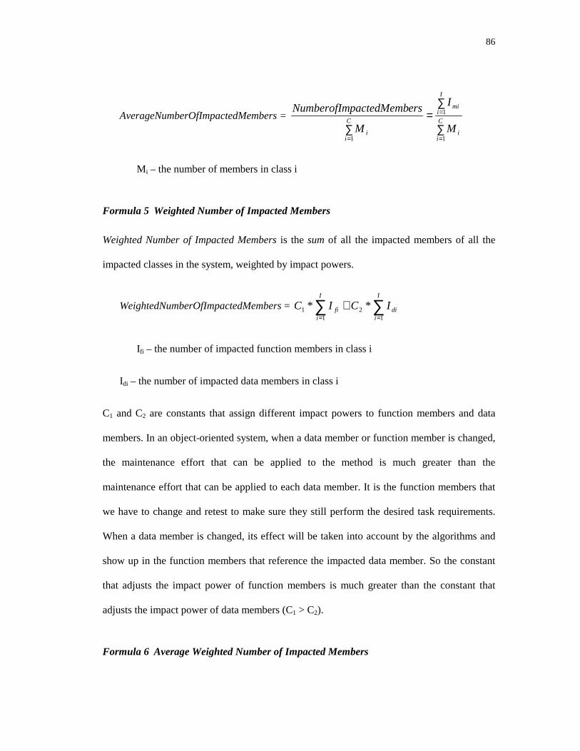
86
AverageNumberOfImpactedMembers = ∑
∑=
∑=
=
=
C
ii
I
imi
C
ii M
I
M
erspactedMembNumberofIm
1
1
1
Mi – the number of members in class i
Formula 5 Weighted Number of Impacted Members
Weighted Number of Impacted Members is the sum of all the impacted members of all the
impacted classes in the system, weighted by impact powers.
WeightedNumberOfImpactedMembers = ∑∑==
+I
idi
I
ifi ICIC
12
11 **
Ifi – the number of impacted function members in class i
Idi – the number of impacted data members in class i
C1 and C2 are constants that assign different impact powers to function members and data
members. In an object-oriented system, when a data member or function member is changed,
the maintenance effort that can be applied to the method is much greater than the
maintenance effort that can be applied to each data member. It is the function members that
we have to change and retest to make sure they still perform the desired task requirements.
When a data member is changed, its effect will be taken into account by the algorithms and
show up in the function members that reference the impacted data member. So the constant
that adjusts the impact power of function members is much greater than the constant that
adjusts the impact power of data members (C1 > C2).
Formula 6 Average Weighted Number of Impacted Members

87
Average Weighted Number of Impact Members is the weighted number of impacted members
divided by the total number of members in the system.
WeightedNumberOfImpactedMembers = ∑=
C
iiM
sctedMembermberOfImpaWeightedNu
1
5.1.2 Derived Object-oriented Change Impact Metrics
This section describes metrics that measure the object-oriented system in more accurate and
elaborate ways. Method Impact Level (MIL) describes the method impact power. Class
Impact Level (CIL) describes the class impact power. System Impact Level (SIL) measures
the impact of a change on the whole system.
Formula 1 Method Impact Level (MIL)
In addition to simply accounting for the number of impacted methods, the size, complexity
and modifiability of the methods play an important role on the impact of change. The Method
Impact Level (MIL) measures the impact inside the method. It considers not only the
impacted variables and statements but also the size and complexity of the method itself.
MIL (method) = C1*Is +C2* Iv + C3*size (method) +C4* VG (method)
C1, C2, C3, and C4 are constants that assign weights to the various terms. Is is the number of
impacted statements in the method, Iv is the number of impacted variables in the method. Size
is a function that counts the token numbers or lines of code (LOC) in the method. VG is the
cyclomatic complexity of the control flow graph (CFG) of the method [McCa76].
VG (method) = (L –N +2)P
L = the number of edges in the CFG.

88
N = the number of nodes in the CFG.
P = the number of disconnected parts in the control flow graph.
The bigger the method is the harder it is to understand and modify it, so the size impacts the
modifiability of the method. VG is used to describe the control complexity side of the
method; some smaller programs could be more difficult to understand and modify because of
their complexity. In the above formula, C1*Is+C2*Iv describes the impacts on the method.
The size and complexity are included to account for the difficulty of modifying the method.
C1, C2, C3, and C4 are independent constants that are used to tune the metrics. The initial
values can be got by the characteristics of the elements. For example, if we think VG
(method), the complexity of the method, impacts the change impact more, we can assign
bigger value to C4 compared with C3. We need to run experiments to find the best suited
value.
Formula 2 Class Impact Level (CIL)
Class Impact Level (CIL) measures the impact level inside the class. It considers the impacts
on methods and on variables, and the contributions of the size and the complexity of the class
to the impact level.
For the classes in the inheritance tree, there are two ways to measure the size of the class: by
considering only local members and by considering local members plus all the inherited
members. For the first case, CIL is:
)*()*()*(
)*())(*()*()*()(
765
41
321
1
iii
di
M
jidi
I
jji
DCRCIC
MCMethdsizeCICMILCclassCILfifi
+++
+++= ∑∑==

89
C1 through C7 are the independent constants to tune the impact powers of different factors.
Mi = the total number of members in class i
Mfi = the total number of function members in class i
Mdi = the total number of data members in class i
Imi = the number of impacted members in class i
Ifi = the number of impacted function members in class i
Idi = the number of impacted data members in class i
size (Methodj) = the size of member j
Ii = the depth of inheritance tree from root to class i
Ri = the number of classes that reference class i
Di = the number of classes referenced by (or defined by) class i
In the above formula, the first two terms, C1*∑ MIL+C2*Idi, measure how much impact the
class i has. The next two terms, C3*∑ size(method)+C4*Mdi, include the size of the method.
The final three terms, C5*Ii+C6*Ui+C7*Ri, measure the coupling and complexity of the class.
The depth of the inheritance tree (Ii) measures the number of parent classes from the root
class to class i. It is the number of classes we may have to understand in order to use a
particular method. The class referencing number (Ri) is the number of use and reference
relationships with other classes for the class i. It describes the number of classes we need to
understand in order to use a particular class. The referenced set (called definition set) number
of a class (Di) measures the number of other classes called by the methods of this class. It is

90
defined as the size of the definition set for the class, which consists of all the methods of the
class and all the methods of other classes called by the methods of the class.
When the size of the class includes the inherited members, the Class Impact Level is:
iiididi
M
ji
erclass
i
V
jdi
I
jji
RCUCICMCMCMethdsizeC
berVisibleMemsizeCICMILCclassCIL
fi
mfi
*****)(*
)(***)(
987651
4
#sup
1 132
11
++++++
++=
∑
∑ ∑∑
=
= ==
In the above formula, Vm is the number of the visible members, which are public and
protected members of a specified class. The size of class i is the sum of all the sizes of the
visible members of its super classes plus the sum of the local members of the class i. The rest
of the parameters are the same as in the previous calculation of CIL.
Formula 3 Cyclomatic Complexity of Object-Oriented Data Dependency Graph
The cyclomatic complexity metrics can be used to measure the complexity of the object-
oriented data dependency graph.
VG (OODDG) = (L –N +2)P
L = the number of edges in the OODDG.
N = the number of nodes in the OODDG.
P = the number of disconnected parts in the OODDG.
Formula 4 System Impact Level (SIL)
System Impact Level (SIL) measures the impact at system level.
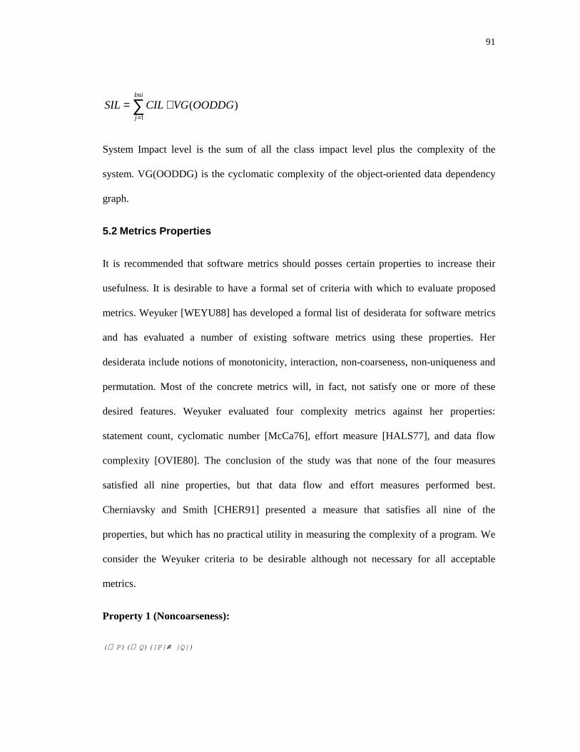
91
)(1
OODDGVGCILSILImi
j
+= ∑=
System Impact level is the sum of all the class impact level plus the complexity of the
system. VG(OODDG) is the cyclomatic complexity of the object-oriented data dependency
graph.
5.2 Metrics Properties
It is recommended that software metrics should posses certain properties to increase their
usefulness. It is desirable to have a formal set of criteria with which to evaluate proposed
metrics. Weyuker [WEYU88] has developed a formal list of desiderata for software metrics
and has evaluated a number of existing software metrics using these properties. Her
desiderata include notions of monotonicity, interaction, non-coarseness, non-uniqueness and
permutation. Most of the concrete metrics will, in fact, not satisfy one or more of these
desired features. Weyuker evaluated four complexity metrics against her properties:
statement count, cyclomatic number [McCa76], effort measure [HALS77], and data flow
complexity [OVIE80]. The conclusion of the study was that none of the four measures
satisfied all nine properties, but that data flow and effort measures performed best.
Cherniavsky and Smith [CHER91] presented a measure that satisfies all nine of the
properties, but which has no practical utility in measuring the complexity of a program. We
consider the Weyuker criteria to be desirable although not necessary for all acceptable
metrics.
Property 1 (Noncoarseness):
(∃ P)(∃ Q)(|P|≠ |Q|)

92
This property is satisfied by nontrivial measures and states that there are at least two
programs with differing measures.
Property 2:
Let c be a non-negative number, then there are only finitely many programs ofcomplexity c.
This property states that there are only a finite number of programs of the same
complexity. This implies that there are no arbitrarily long programs of fixed measures.
Property 3:
(Nonuniqueness): There are distinct programs P and Q such that |P| = |Q|
This property again asserts that the measure is nontrivial, in that there are multiple
programs having the same measure.
Property 4 (Importance of Implementation):
(∃ P)(∃ Q)(P ≡ Q and |P|≠ |Q|)
This property expresses the condition that there are functionally equivalent programs
with different complexities.
Property 5 (Monotonicity):
(∀ P)(∀ Q)(|P|≤ |P; Q| and |Q|≤ |P; Q|)
P;Q means Q follows P. This property is satisfied for monotonic measures. It roughly
expresses that adding on to a program makes a more complex program.
Property 6a (Nonequivalence of Interaction):
(∃ P)(∃ Q)(∃ R)(|P|=|Q| and |P; R|≠ |Q; R|)
93
This property is a contextual property. Code occurring after different but equally
complex prologues may be differently impacted by the distinct prologues (at least
regarding its complexity). This is an inter-program property.
Property 6b(Nonequivalence of Interaction):
(∃ P)(∃ Q)(∃ R)(|P|=|Q| and |R; P|≠ |R; Q|)
This property is similar to the previous one except that the identical code occurs at the
beginning of the program.
Property 7 (Nonequivalence of Permutation):
There are program bodies P and Q such that Q is formed by permuting the order ofstatements of P and |P|≠ |Q|.
This is again a contextual property, but more of an intra-program contextual property.
Thus changing the order of statements may change the complexity of the program.
Property 8:
If P is a renaming of Q, then |P| = |Q|.
This property states that uniformly changing variable names should not impact a
program’s complexity.
Property 9 (Interaction Increases Complexity):
(∃ P)(∃ Q)(|P|+|Q|< |P+Q|)
P+Q means P combined with Q. |P| is used to describe the complexity of P. This property
states that a combined program may be more complex than its constituent parts.
Our object-oriented change impact metrics mentioned in this section satisfies all of
Weyuker’s criteria except property 7, which does not apply.

94
It is not surprising to have two different programs to have different impact values. There are
a lot of factors in the system that causes two program to have different impact metrics, so the
impact metrics satisfy property 1. As described above, all the impact metrics have upper
bounds and lower bounds, so they satisfy property 2.
They satisfy property 3, because two different programs can have the same level of impact.
For example, two different systems have the same isolated class or function, and this class or
function is proposed as the change source. Under this situation, the only class or function
being impacted is the class or function shown in the change criteria itself. Because the class
or the function is the same in both systems, the impact values on both systems are the same.
As long as two programs have different implementation classes and relationships, they might
have different impacts even if their functionality are the same. The impact metrics satisfy
property 4.
These metrics satisfy property 5. Two programs connected together can only increase the
complexity, not decrease the amount of impact a change can have, so |P| ≤ |P; Q| and |Q| ≤ |P;
Q|.
For property 6a and 6b, if |P; R| and |Q; R| change the dependencies between P and Q, it will
satisfy 6a and b. Our algorithms focus on method level, so property 7 does not apply to our
metrics. Renaming will not change dependency, so our metrics satisfy property 8. For
property 9, if P+Q adds more dependencies than before they are combined, |P+Q| will have
more impact than the two programs P and Q by themselves. Thus, these metrics satisfy
property 9.
95
6 INFERENCE APPROACH
In this section, we discuss our algorithms from another point of view. The impact calculating
algorithms described in previous sections are expressed in data base deductive rules. The
advantage of this approach is that we can take advantage of the deductive capability of logic
database to let users compose their own questions to the system.
6.1 Datalog
Datalog is a logic-based data model. Its name hints that it is a version of Prolog suitable for
database systems. Prolog statements are composed of atomic formulas, which consist of a
predicate symbol applied, as if it were a procedure name, to arguments. These arguments
may later be applied to arguments just as we would call a function in an ordinary
programming language. Predicate symbols should be thought of as producing true or false as
a result; i.e., they are Boolean-valued functions. Function symbols, on the other hand, may be
thought of as producing values of any type one wishes. Datalog does not allow function
symbols in arguments, but allows variables and constants as arguments of predicates. Atomic
Formulas in datalog are formally defined as predicate symbols with a list of arguments, p
(A1, ..., An), where p is a predicate symbol. An argument in datalog can be either a variable or
a constant, for example, employee (Name, “Software Department”, salary, address).

96
In the datalog model, a literal is either an atomic formula or a negated atomic formula; a
clause is a sum (logical or) of literals. A horn clause is a clause with at most one positive
literal. It is either:
• A single positive literal, p (X, Y), which we regard as a fact.
• One or more negative literals, with no positive literal, which is an integrity constraint, or
• A positive literal and one or more negative literals, which is a rule.
Logical statements, often called rules, will usually be expressed in the form of Horn Clauses.
In “B: - A1 & A 2 & ... & An”, (read as if A1 and A2 and ... An are true, then B is true), B is the
head of the rule and the part after ”: - “is the body of the rule. The horn clause¬ p1 v...v
¬ pn v q is logically equivalent to p1∧ p2...pn --> q, or q :- p1, p2, … pn, which is a
statement of the form: “If p1 and p1 and ... pn are true, then q is true.” A datalog program is a
set of rules.
Logic rules are often used to express dependency relationships. To do so, we can draw a
dependency graph, whose nodes are the ordinary predicates. There is an arc from predicate p
to predicate q if there is a rule with a sub-goal whose predicate is p and with a head whose
predicate is q. A logic program is recursive if its dependency graph has one or more cycles.
All the predicates that are on one or more cycles are said to be recursive predicates. A logic
program with an acyclic dependency graph is nonrecursive.
Suppose we have a relation Parent (p, c), meaning p is c’s parent, and a relation ancestor (a,
c), meaning a is c’s ancestor. a is c’s ancestor if (1) a is c’s parent or (2) a is b’s ancestor and
b is c’s parent. Ancestor is the transitive closure of parent. In datalog logic rules, this is
expressed as:

97
Ancestor (p, c): - Parent (p, c).
Ancestor (a, c): - Ancestor (a, b), Parent (b, c).
This example is a recursive program, and its dependency graph is:
Ancestor
Parent
Figure 18. Dependency Graph
A predicate whose relation is stored in the database is called an extensional database (EDB).
A predicate defined by logical rules is called an intentional database (IDB).
6.1.1 Facts in the Algorithms
This section lists some of the facts that the system can store as defaults, and explains their
semantics. Users can add their own facts if needed. Following is a list of facts that describe
the entity relationship of the object-oriented system.
• Class Member Category
A class member can either be a method or a data member. If a class member is not a method
it can imply that it is a data member, and vice versa.
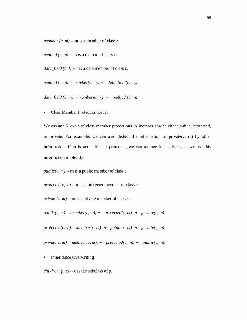
98
member (c, m) -- m is a member of class c.
method (c, m) -- m is a method of class c.
data_field (c, f) -- f is a data member of class c.
method (c, m): - member(c, m), ¬ data_field(c, m);
data_field (c, m): - member(c, m), ¬ method (c, m);
• Class Member Protection Level:
We assume 3 levels of class member protections. A member can be either public, protected,
or private. For example, we can also deduct the information of private(c, m) by other
information. If m is not public or protected, we can assume it is private, so we use this
information implicitly.
public(c, m) -- m is a public member of class c.
protected(c, m) -- m is a protected member of class c.
private(c, m) -- m is a private member of class c.
public(c, m): - member(c, m), ¬ protected(c, m), ¬ private(c, m);
protected(c, m): - member(c, m), ¬ public(c, m), ¬ private(c, m);
private(c, m): - member(c, m), ¬ protected(c, m), ¬ public(c, m);
• Inheritance Overwriting
children (p, c) -- c is the subclass of p.

99
p-overwrite (p, m, c, n) -- n in class c partially overwrites m in class p. It means n extends the
service of m by calling the original m.
c-overwrite (p, m, c, n) -- n in class c completely overwrites m in class p.
inherit (p, m, c, n) -- n in class c completely inherits the behavior of m in p.
Methods in children’s classes can overwrite the methods in parents’ classes to have different
behavior. The children’s method can totally rewrite the parent’s method, expand the parent’s
method by adding some operations to the original method or inherit all the service of the
parent’s method without any change. inherit (p, m, c, n) is true if n in class c completely
inherits the behavior of m in p. p-overwrite(p, m, c, n) is true if n in class c partially
overwrites m in p by using m’s service from p. c-overwrite(p, m, c, n) is true if the method in
a child class completely redefines the behavior of the same method in its parent; any change
to this method of the parent will not impact the corresponding method of the child. From the
characteristics of inheritance, the parent does not depend on the children. So any change in a
child will not impact the parent. In the default system, we only store the facts and rules that
relate to the change impact of the system. For example, when a method in a child completely
overwrites the parent’s method, a change to the parent will not impact the child. So the
system will not initially store the relationship between the method of the children and the
method of the parent. Users can add their own facts and rules if needed.
Following is an example of inherit and p-overwrite. Class C is a subclass of class P. Class P
has virtual methods method_1, method_2, and method_3. C has virtual methods method_1
and method_2.
class P {
public:
virtual void method_1(int x, int y);
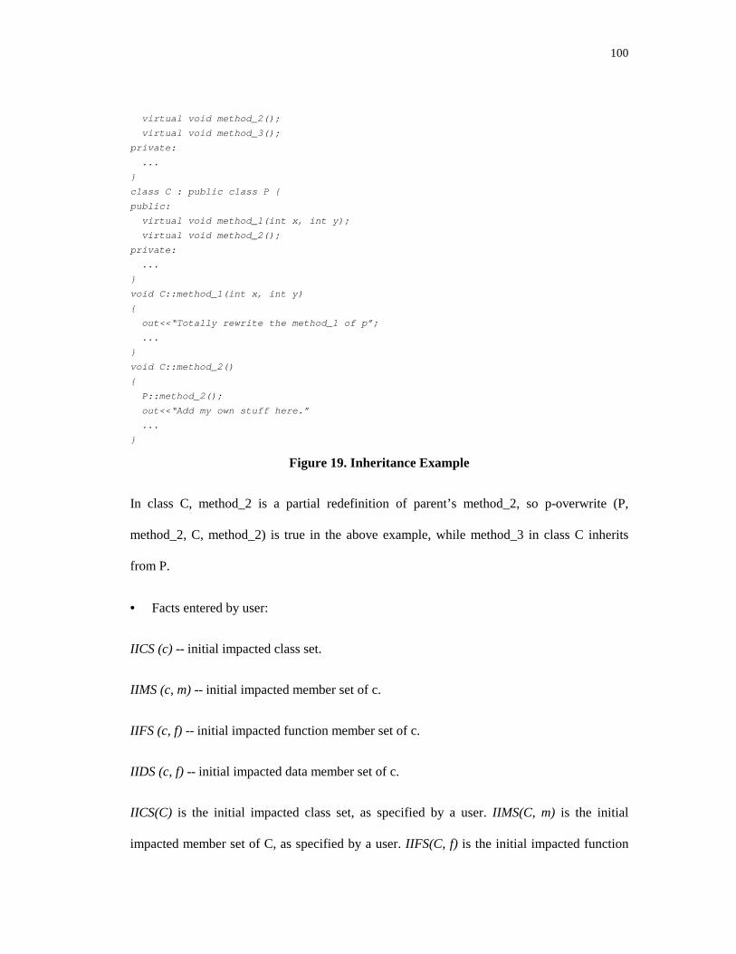
100
virtual void method_2();
virtual void method_3();
private:
...
}
class C : public class P {
public:
virtual void method_1(int x, int y);
virtual void method_2();
private:
...
}
void C::method_1(int x, int y)
{
out<<“Totally rewrite the method_1 of p”;
...
}
void C::method_2()
{
P::method_2();
out<<“Add my own stuff here.”
...
}
Figure 19. Inheritance Example
In class C, method_2 is a partial redefinition of parent’s method_2, so p-overwrite (P,
method_2, C, method_2) is true in the above example, while method_3 in class C inherits
from P.
• Facts entered by user:
IICS (c) -- initial impacted class set.
IIMS (c, m) -- initial impacted member set of c.
IIFS (c, f) -- initial impacted function member set of c.
IIDS (c, f) -- initial impacted data member set of c.
IICS(C) is the initial impacted class set, as specified by a user. IIMS(C, m) is the initial
impacted member set of C, as specified by a user. IIFS(C, f) is the initial impacted function

101
member set of C that the users specify. IIDS(C, f) is the initial impacted data member set of
C that the users specify.
6.1.2 Rules
In this section, we describe some of the default rules to calculate change impacts of an
object-oriented system and explain the semantic meanings of these rules. Users can expand
or customize the system and algorithms by adding or removing rules from the system. For
example, we define 3 levels of member and instance protections, public, protected, and
private. Some people view Java as having four levels of protection, public, protected,
private, and package. To extend the algorithm to take care of this fourth level of protection,
It is necessary to add one extra fact, package(c, m) and associated corresponding rules.
6.1.2.1 Reference Set and Definition Set
The Reference set of class member m includes all those variables that reference m directly or
indirectly. For example, the fact that class c2’s member m2 references class c1’s member m1
can be represented as ref (c1, m1, c2, m2). Class c2’s member m2 directly references class
c1’s member m1 if there is an edge from c2’s m2 to c1’s m1 in the dependency graph (this
can be expressed as direct-ref (c1, m1, c2, m2)).
ref (c1, m1, c2, m2) :- direct-ref(c1, m1, c2, m2)
ref (c1, m1, c3, m3) :- ref(c1, m1, c2, m2) direct_ref(c2, m2, c3, m3)
ref (c1, m1, c2, m2) :- direct-ref (c1, m1, c2, m2) says that if c2::m2 is a member of c1::m1‘s
direct reference set, then we can say c2::m2 is also a member of c1::m1’s reference set.
ref (c1, m1, c3, m3) :- ref (c1, m1, c2, m2), direct_ref(c2, m2, c3, m3) says that if c2::m2
belongs to c1::m1’s reference set, and c3::m3 belongs to c2::m2’s reference set, then c3::m3
belongs to c1::m1’s reference set.

102
Following is an example of a method m in C that references method n and data member y in
C:
void c1::m() {
c2 vc2;
...
c1::n();
x = c1::m2() + vo2.y;
...
}
Figure 20. Method m references method n and data member y in C1
In the above example, ref (c1, m, c1, n), ref (c1, m, c1, m2), and ref (c1, m, c2, y) are true
because m reference n, m2, and y as part of its implementation. Here is another example of a
data member x that references method m and data member y in c1.
...
c1 obj1;
c2 obj2;
obj2.x = obj1.m + obj1.y;
...
Figure 21. Data member x in c1 references method m and data member y in c1
In this example, ref (c2, x, c1, m) and ref (c2, x, c1, y) are true because c2’s x references c1’s
m and y in its definition.
6.1.2.2 Inside the class
A class member defined in a class can access everything inside that class. A member could
be impacted if it references any other members in the class that have already been impacted
1) member(c, f) :- method (c, f)
2) member(c, d) :- data_field(c, d)
3) IFS(c, f) :- IFS(c, m), method(c, f), ref(c, f, c, m)
4) IFS(c, f) :- IDS(c, d), method(c, f), ref(c, f, c, d)
5) IDS(c, d) :- IFS(c, n), data_field(c, m), ref(c, d, c, n)
6) IDS(c, d) :- IDS(c, x), data_field(c, m), ref(c, d, c, x)

103
Rule number one and number two say that method and data member are class members. Rule
number three means f is an impacted function member of class c if method f in c references
member m in c, and m has been impacted. The fourth rule means f is an impacted function
member of class c if f in c references the data member d in c, and d has been impacted. The
same rule holds for IDS. The fifth rule means d is an impacted data member of c if d
references method m and m has been impacted. The sixth rule means d is an impacted
member of c if d references data member x in c and x has been impacted.
6.1.2.3 Inheritance
If a class c is a child class of class parent, and method m in parent and method m in c have
the same signature, there are several rules for m in c related to m in parent:
• Each method in class c could inherit the method in class parent without change. In this
situation, any change in method m will impact the m of subclass c.
IFS(c, m) :- ICS(parent), children(parent, c), method(c, m), inherit(parent, m, c, m),IFS(parent, m)
The above rule says if the parent is an impacted class, c is a subclass of the parent, m in c
inherits the m of the parent without change, and if m in the parent is impacted, then m in c
could also be impacted.
• The m in subclass c can expand the service of its parent by using the service of its parent
and adding its own functions. In this situation, any changes in m of parent will impact m in
subclass c also.
IFS(c, m) :- ICS(parent), children(parent, c), method(c, m), p-overwrite(parent, m, c,m), IFS(parent, m)
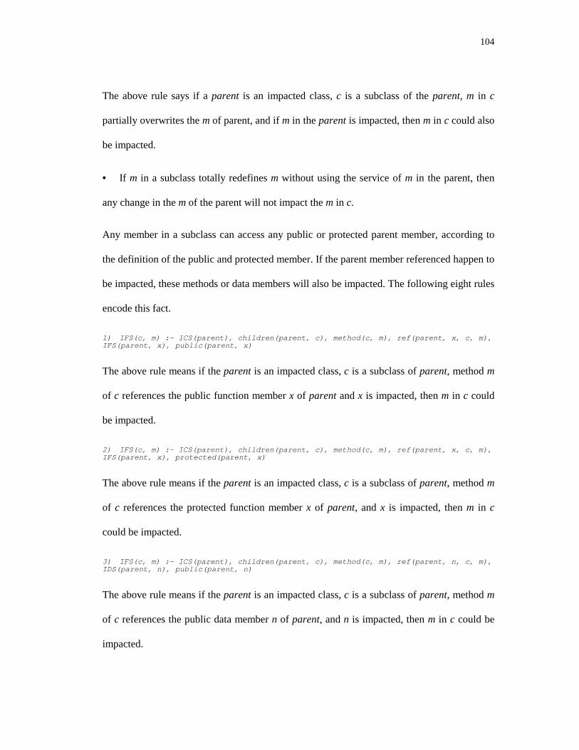
104
The above rule says if a parent is an impacted class, c is a subclass of the parent, m in c
partially overwrites the m of parent, and if m in the parent is impacted, then m in c could also
be impacted.
• If m in a subclass totally redefines m without using the service of m in the parent, then
any change in the m of the parent will not impact the m in c.
Any member in a subclass can access any public or protected parent member, according to
the definition of the public and protected member. If the parent member referenced happen to
be impacted, these methods or data members will also be impacted. The following eight rules
encode this fact.
1) IFS(c, m) :- ICS(parent), children(parent, c), method(c, m), ref(parent, x, c, m),IFS(parent, x), public(parent, x)
The above rule means if the parent is an impacted class, c is a subclass of parent, method m
of c references the public function member x of parent and x is impacted, then m in c could
be impacted.
2) IFS(c, m) :- ICS(parent), children(parent, c), method(c, m), ref(parent, x, c, m),IFS(parent, x), protected(parent, x)
The above rule means if the parent is an impacted class, c is a subclass of parent, method m
of c references the protected function member x of parent, and x is impacted, then m in c
could be impacted.
3) IFS(c, m) :- ICS(parent), children(parent, c), method(c, m), ref(parent, n, c, m),IDS(parent, n), public(parent, n)
The above rule means if the parent is an impacted class, c is a subclass of parent, method m
of c references the public data member n of parent, and n is impacted, then m in c could be
impacted.

105
4) IFS(c, m) :- ICS (parent), children(parent, c), method(c, m), ref(parent, n, c,m), IDS(parent, n), protected(parent, n)
The above rule means if the parent is an impacted class, c is a subclass of parent, method m
of c references the protected data member n of parent, and n is impacted, then m in c could
be impacted.
5) IDS(c, d) :- ICS (parent), children(parent, c), data_field(c, d), ref(parent, x,c, d), IFS(parent, x), public(parent, x)
This rule means if the parent is an impacted class, c is a subclass of parent, data member d of
c references the public function member x of parent, and x is impacted, then d in c could be
impacted.
6) IDS(c, d) :- ICS (parent), children(parent, c), data_field(c, d), ref(parent, x,c, d), IFS(parent, x), protected(parent, x)
This rule means if the parent is an impacted class, c is a subclass of parent, data member d of
c references the protected function member x of parent, and x is impacted, then d in c could
be impacted.
7) IDS(c, d) :- ICS (parent), children(parent, c), data_field(c, d), ref(parent, m,c, d), IDS(parent, m), public(parent, m)
This rule means if the parent is an impacted class, c is a subclass of parent, data member d of
c references the public data member x of parent, and x is impacted, then d in c could be
impacted.
8) IDS(c, d) :- ICS (parent), children(parent, c), data_field(c, d), ref(parent, m,c, d), IDS(parent, m), protected(parent, m)
This rule means if the parent is an impacted class, c is a subclass of parent, data member d of
c references the protected member x of parent, and x is impacted, then f in c could be
impacted.

106
6.1.2.4 Use Relationship
If an impacted method or data member in c0 is public, any other class can access it and can
potentially become impacted. The following six rules are used.
1)PIFS(c, m) :- IFS(c, m), public(c, m)
This rule says that if m is a public method of c and m is impacted, then m is a public
impacted method.
2)PIDS(c, f) :- IDS(c, f), public(c, f)
This rule says that if f is a public data member of c and f is impacted, then f is a public
impacted data member.
3) IFS(c, m) :- client (c0, c), method(c, m), ref(c0, n, c, m), PIFS(c0, n)
This rule says if c is a client of c0, c’s method m references c0’s method n and n is a public
impacted method of c0, then m could be impacted.
4) IFS(c, m) :- client (c0, c), method(c, m), ref(c0, f, c, m), PIDS(c0, f)
This rule says if c is a client of c0, c’s method m references c0’s data member f and f is a
public impacted data member of c0, then m could be impacted.
5) IDS(c, f) :- client (c0, c), data_field(c, f), ref(c0, n, c, f), PIFS(c0, n)
This rule says if c is a client of c0, c’s data member f references c0’s method n and n is a
public impacted method of c0, then f could be impacted.
6) IDS(c, f) :- client (c0, c), data_field(c, f), ref(c0, x, c, f), PIDS(c0, x)
This rule says if c is a client of c0, c’s data member f references c0’s data member x and x is a
public impacted data member of c0, then f could be impacted.
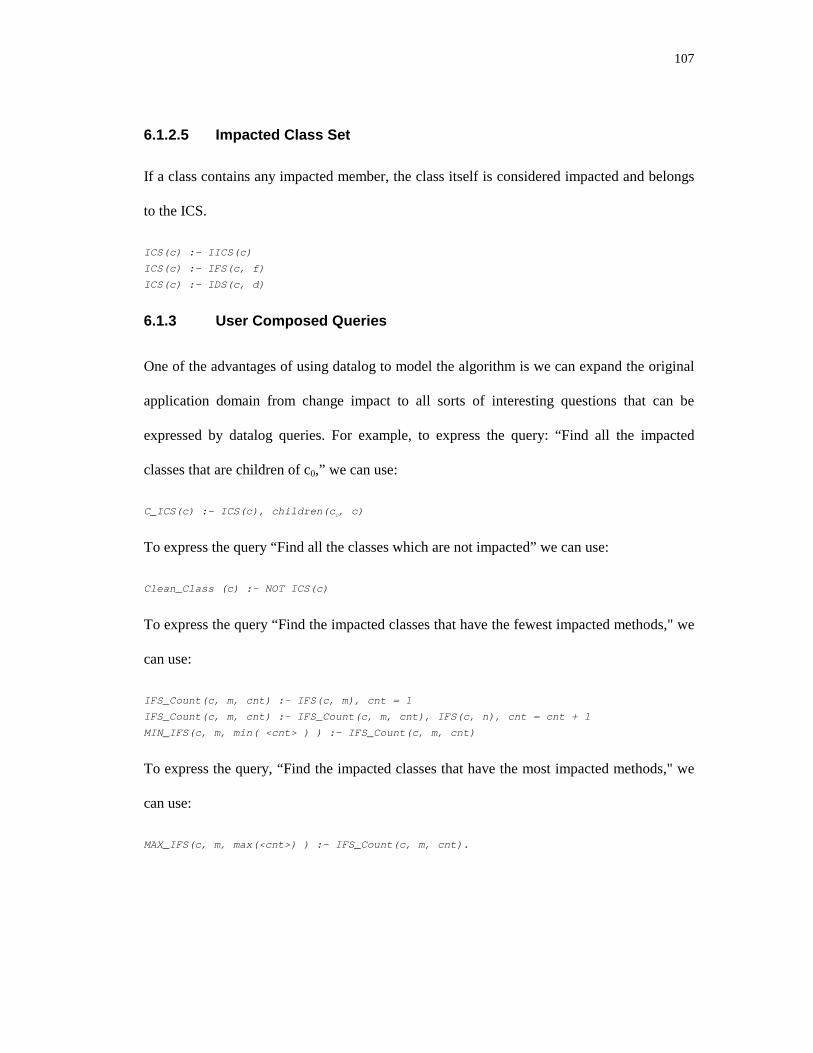
107
6.1.2.5 Impacted Class Set
If a class contains any impacted member, the class itself is considered impacted and belongs
to the ICS.
ICS(c) :- IICS(c)
ICS(c) :- IFS(c, f)
ICS(c) :- IDS(c, d)
6.1.3 User Composed Queries
One of the advantages of using datalog to model the algorithm is we can expand the original
application domain from change impact to all sorts of interesting questions that can be
expressed by datalog queries. For example, to express the query: “Find all the impacted
classes that are children of c0,” we can use:
C_ICS(c) :- ICS(c), children(c0, c)
To express the query “Find all the classes which are not impacted” we can use:
Clean_Class (c) :- NOT ICS(c)
To express the query “Find the impacted classes that have the fewest impacted methods," we
can use:
IFS_Count(c, m, cnt) :- IFS(c, m), cnt = 1
IFS_Count(c, m, cnt) :- IFS_Count(c, m, cnt), IFS(c, n), cnt = cnt + 1
MIN_IFS(c, m, min( <cnt> ) ) :- IFS_Count(c, m, cnt)
To express the query, “Find the impacted classes that have the most impacted methods," we
can use:
MAX_IFS(c, m, max(<cnt>) ) :- IFS_Count(c, m, cnt).

108
7 PROOF-OF-CONCEPT EXPERIMENTAL SYSTEM
This chapter describes the structure and design of the proof-of-concept system called Change
Impact Analysis Tool (ChAT). Section 7.1 describes the environment and the context of
ChAT. Section 7.2 outlines the architecture and high level design of the tool. Section 7.3
presents the empirical results used to verify the algorithms.
7.1 System Context
ChAT is implemented in C++ and Java, and runs on multiple platforms. We have tried it on
Solaris 5.4 and NT platform. There are three major parts in ChAT: Parser, Analyzer, and
Viewer. The parser is extended from the gnu software g++ that is written in yacc, lex and C,
which is composed of roughly 445000 lines of yacc, lex and C code and 6600 lines of C++
code to interpret the tree node of g++ and transfer it to the information format the analyzer
needs. The implementation difficult in this phase lies in understanding the complicated
structures and implementation details. Analyzer consists of 2300 lines of Java code. Viewer
is written in Java JFC, it is about 2200 lines of Java code.
ChAT provides a convenient environment for users. The legacy programs can be compiled,
analyzed and viewed without leaving the environment. Classes in the system are shown in a
tree hierarchy. When ChAT compiles a program, it extracts information for later analysis.
After a user specifies the changes by choosing the different class members or classes in the
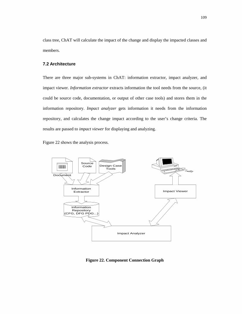
109
class tree, ChAT will calculate the impact of the change and display the impacted classes and
members.
7.2 Architecture
There are three major sub-systems in ChAT: information extractor, impact analyzer, and
impact viewer. Information extractor extracts information the tool needs from the source, (it
could be source code, documentation, or output of other case tools) and stores them in the
information repository. Impact analyzer gets information it needs from the information
repository, and calculates the change impact according to the user’s change criteria. The
results are passed to impact viewer for displaying and analyzing.
Figure 22 shows the analysis process.
SourceCode
Impact Analyzer
InformationExtractor
InformationRepository
(CFG, DFG PDG...)
Impact Viewer
Document
Design CaseTools
Figure 22. Component Connection Graph

110
The target of ChAT is object-oriented software written in C++. ChAT could be extended to
handle software written in other languages like Java and Small Talk by using a different
information extractor. Information extractor can also be expanded to extract information
from other information sources like document and other case tools. If the analysis target is a
design document, the information extractor could be a set of application programming
interferences (APIs) that work with the case tool to extract the relationships of the objects
described in the document. The current implementation only analyzes source code.
The framework of ChAT (shown in
Figure 23) connects the different components of the architecture. Although the tool created
for this research only handles C++, the tool is flexible enough to handle different languages,
accept different algorithms, and handle new requirements as the system evolves by plugging
in different components into the framework as long as these components follow the interface
of the framework.
C++Parser
Concretecomponents
to choose from
SetAnalysisEngine
DatalogInferenceEngine
JavaParser
GraphAnalysisEngine
MatrixAnalyzerEngine
I
InformationRepository
Information
Extractor
CaseToolInfo.
Extractor
Analyzer
Figure 23. Framework
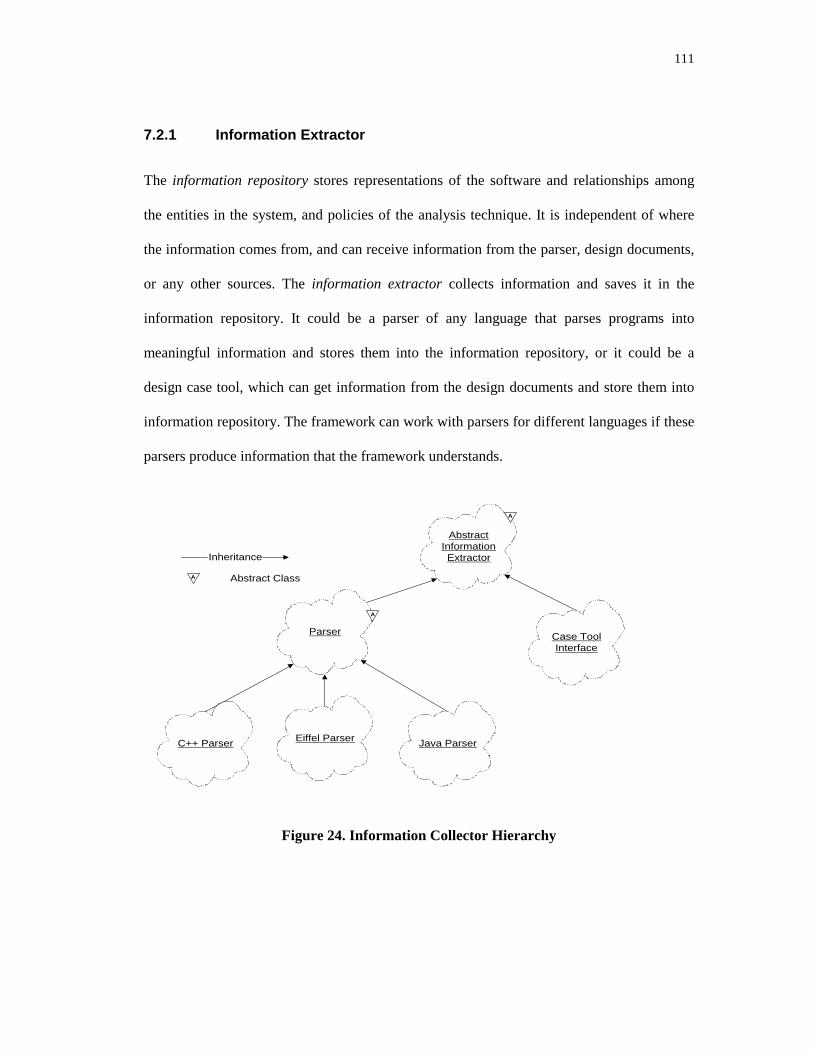
111
7.2.1 Information Extractor
The information repository stores representations of the software and relationships among
the entities in the system, and policies of the analysis technique. It is independent of where
the information comes from, and can receive information from the parser, design documents,
or any other sources. The information extractor collects information and saves it in the
information repository. It could be a parser of any language that parses programs into
meaningful information and stores them into the information repository, or it could be a
design case tool, which can get information from the design documents and store them into
information repository. The framework can work with parsers for different languages if these
parsers produce information that the framework understands.
AbstractInformationExtractor
Parser Case ToolInterface
C++ Parser Eiffel Parser Java Parser
Inheritance
A
A
A Abstract Class
Figure 24. Information Collector Hierarchy

112
7.2.2 Impact Analyzer
Analyzer defines the interface for the analysis techniques. As long as we keep the analyzer
interface the same, changing the analysis technique will not impact the framework. Other
possible analyzers include an analyzer that calculates change impacts by set operations, an
analyzer that uses deductive database rules, an analyzer that calculates change impacts by
graph theory, or an analyzer that calculates change impacts by a propagation matrix (as
illustrated in Figure 25). ChAT is implemented using the set operation approach. The
inference approach is discussed in chapter 0. Other implementation approaches of the
algorithms are left for future work.
Analyzer
Matrix AnalysisEngine
Graph AnalysisEngine
Set AnalysisEngine
Datalog InferenceEngine
Inherited from
Contain by Reference
Contain by Value
Use
Figure 25. Analyzer Class Hierarchy.
The class diagram in Figure 26 describes the static structure of the analyzer. Class
EffectFinder is responsible for the top-level control of the impact calculating algorithms. Its
data members include _total_class_set, which holds the information for all the classes in the
system, and _impacted_class_set, which stands for a set of impacted classes. _total_class_set
and _impacted_class_set are a set of objects, which are instances of ClassInfo. ClassInfo
contains information about a specific class. It contains a set of ClassMemberInfo classes,
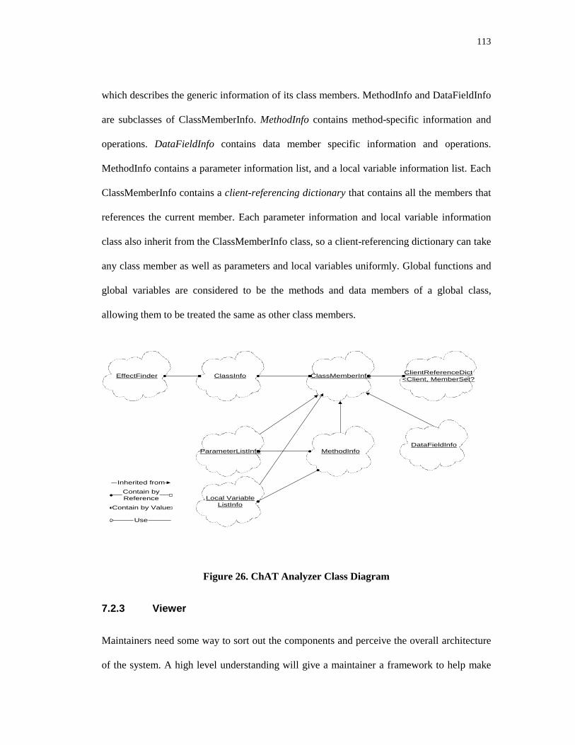
113
which describes the generic information of its class members. MethodInfo and DataFieldInfo
are subclasses of ClassMemberInfo. MethodInfo contains method-specific information and
operations. DataFieldInfo contains data member specific information and operations.
MethodInfo contains a parameter information list, and a local variable information list. Each
ClassMemberInfo contains a client-referencing dictionary that contains all the members that
references the current member. Each parameter information and local variable information
class also inherit from the ClassMemberInfo class, so a client-referencing dictionary can take
any class member as well as parameters and local variables uniformly. Global functions and
global variables are considered to be the methods and data members of a global class,
allowing them to be treated the same as other class members.
EffectFinder ClassInfo ClassMemberInfo
MethodInfoDataFieldInfo
ClientReferenceDict<Client, MemberSet?
ParameterListInfo
Local VariableListInfo
Inherited from
Contain byReference
Contain by Value
Use
Figure 26. ChAT Analyzer Class Diagram
7.2.3 Viewer
Maintainers need some way to sort out the components and perceive the overall architecture
of the system. A high level understanding will give a maintainer a framework to help make

114
sense of the more detailed information acquired as specific maintenance tasks are
undertaken. A calling hierarchy is a useful tool for understanding systems designed using
functional decomposition approaches in which the main packaging unit is the processing
module. In such systems, the top level “main module” will likely be a good place to start in
system understanding and, if the modules subordinate to it are reasonably cohesive,
examining them may give a quick overview of system functions. But in object-oriented
programs, the calling hierarchy is a hierarchy of methods, which has several disadvantages.
First, the dynamic binding problem makes the hierarchy difficult to compute. Second, there
may be no real “main” method in the system. This is a fact about object-oriented that
beginners tend to find disconcerting. Finally, a hierarchy of methods loses sight of the
grouping of methods in objects, which is presumably the most important aspect of the design.
An obvious understanding aid would be the object class hierarchy, but because it groups
objects with similar methods, it fails to show how the objects combine to provide the
different functional capabilities of the program. One possible high-level viewer would be a
display of the class diagram. The result is a graph rather than hierarchy. This is clearer when
there are relatively few classes in the system. When the system contains a large number of
classes, the graph becomes very difficult to understand. In general, graphs are notoriously
more difficult to display and comprehend than trees.
The prototype tool ChAT presents the results in five types of display: all class tree view,
impact only tree view, change input table, member impact table, and class impact table. The
all class tree view shows the hierarchy of all the classes in the system. Each class node
includes a member view node, a children classes node, and a client classes node. Member
view node contains all the members of that class. Children classes node displays all its sub-
classes and client classes node contains all the classes that reference this class. Classes and

115
members picked by the user are displayed in magenta and times roman font (initial change
mode), the impacted classes and their members are displayed in red and arial black font
(impacted mode), and the not impacted ones are displayed in blue and courier font (clean
mode)1. Impact only tree view is similar to all class tree view, but instead of showing all the
classes and their class members, it only displays the impacted classes and their impacted
members. This figure allows users to concentrate on analyzing the impacted parts of the
system. Member impact table lists all the impacted class members and their member impact
level. Class impact table lists all the impacted classes and related metrics such as number of
impacted members in the class, average number of impact members in the class and the class
impact level. The change input table displays only initial change classes that are specified by
the user.
1 Fonts are added to express the node states, for readers to view clearly in normal print out.

116
7.3 Empirical Results
This section demonstrates, by a set of examples, how the technique presented in this research
can help developers keep track of change impacts in their software. There are five
subsections in this section. Each subsection presents an example that is designed to capture
the different relationships in object-oriented software. Some of the examples put more
emphasis on one kind of relationship while others combine different relationships together to
simulate a real world problem. Section 7.3.1 presents an example explaining how changes
propagate inside the class when there are no dependency relationship among class members.
Section 7.3.2 gives a similar example but with a cyclic dependency relationship among class
members. Section 7.3.3 shows how the algorithms handle the use and containment
relationships among classes through an example. Section 7.3.4’s example helps us
understand how the changes propagate through inheritance and how polymorphism plays a
role in the change propagation. Section 7.4 applies ChAT to some modules of a commercial
product, and analyzes the change impacts among these modules when changes are invoked
from different modules.
7.3.1 Change Propagation Inside Classes
This section uses a simple example to explain how changes propagate inside the class among
class members. This example has only one class with an acyclic dependency relationship
among its class members.
/* The example tests propagation inside the class */
class ClassA {
public:
int A_meth1();
int A_meth2() {
…
_A_field2 = A_meth1();
…
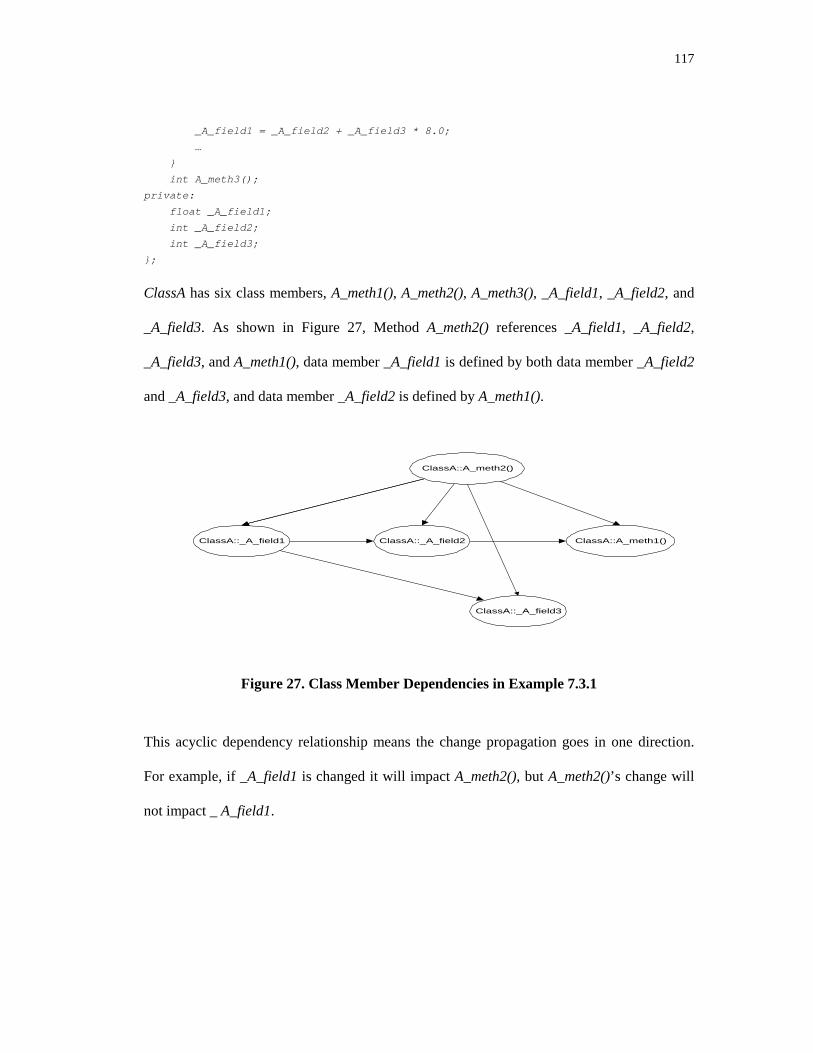
117
_A_field1 = _A_field2 + _A_field3 * 8.0;
…
}
int A_meth3();
private:
float _A_field1;
int _A_field2;
int _A_field3;
};
ClassA has six class members, A_meth1(), A_meth2(), A_meth3(), _A_field1, _A_field2, and
_A_field3. As shown in Figure 27, Method A_meth2() references _A_field1, _A_field2,
_A_field3, and A_meth1(), data member _A_field1 is defined by both data member _A_field2
and _A_field3, and data member _A_field2 is defined by A_meth1().
ClassA::_A_field1
ClassA::A_meth2()
ClassA::A_meth1()ClassA::_A_field2
ClassA::_A_field3
Figure 27. Class Member Dependencies in Example 7.3.1
This acyclic dependency relationship means the change propagation goes in one direction.
For example, if _A_field1 is changed it will impact A_meth2(), but A_meth2()’s change will
not impact _ A_field1.

118
Figure 28 through Figure 31 show the results yielded when A_meth1() in ClassA is specified
as the initial change class member.
The tree in Figure 28 shows all the members in ClassA with A_meth1() in initial change
mode, A_meth2(), _A_field1 and _A_field2 in impacted mode, and other not impacted
members in clean mode. The metrics result box shows that there are 4 impacted method
numbers in this example.
Initial change mode
Affected mode
Clean mode
Figure 28. All Class Tree View in Example 7.3.1
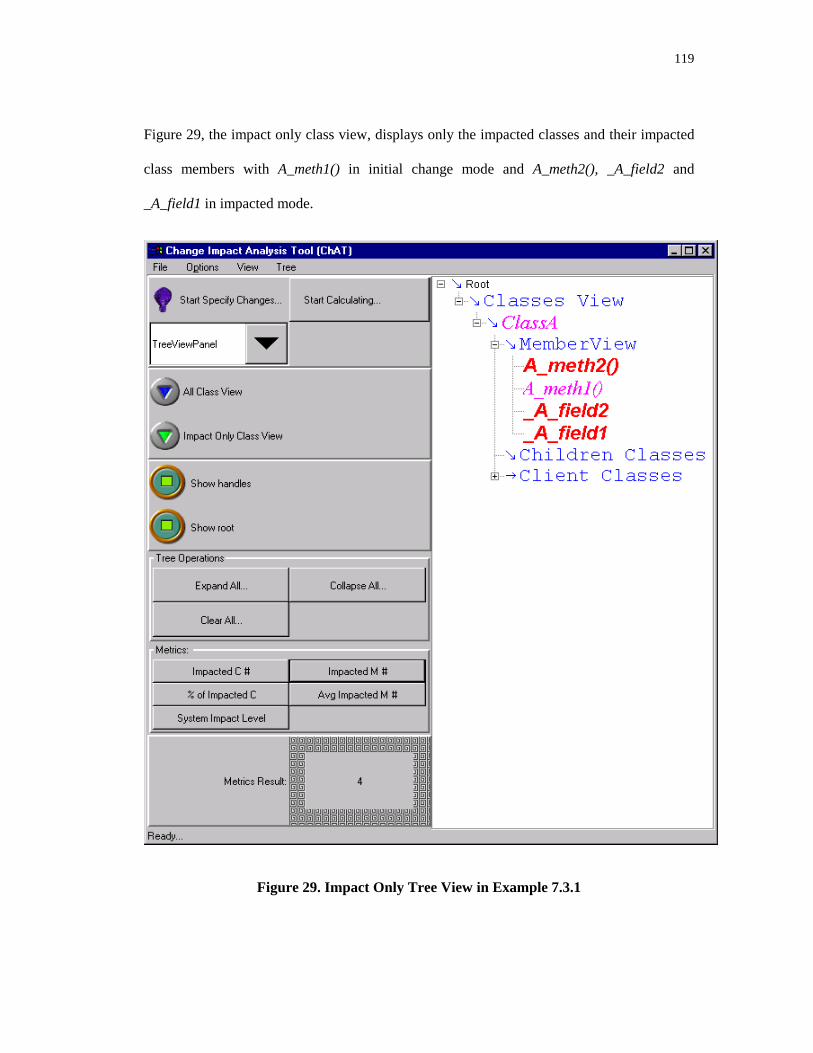
119
Figure 29, the impact only class view, displays only the impacted classes and their impacted
class members with A_meth1() in initial change mode and A_meth2(), _A_field2 and
_A_field1 in impacted mode.
Figure 29. Impact Only Tree View in Example 7.3.1

120
Figure 30, the impact table, displays the impacted classes and their impacted class members
in a table. The table shows ClassA::A_meth1(), ClassA::A_meth2(), ClassA::_A_field1, and
ClassA::_A_field2 are impacted, and their impact level are 24, 12, 3, and 3. The average
impacted method number of this example is 0.5, which means half of the members in this
example are impacted (as shown in metrics result box.)
Figure 30. The Impact Table in Example 7.3.1

121
Figure 31, the class impact table, shows the impacted classes and their related class level
change impact metrics. The table shows ClassA is the impacted class. Its number of impacted
members is 4, its average number of impacted member is 0.5, and its class impact level is 42.
The metrics result box shows the system impact level is 42. Because ClassA is the only class
in this example, the system impact level is equal to ClassA’s class impact level.
Figure 31. The Class Impact Table in Example 7.3.1
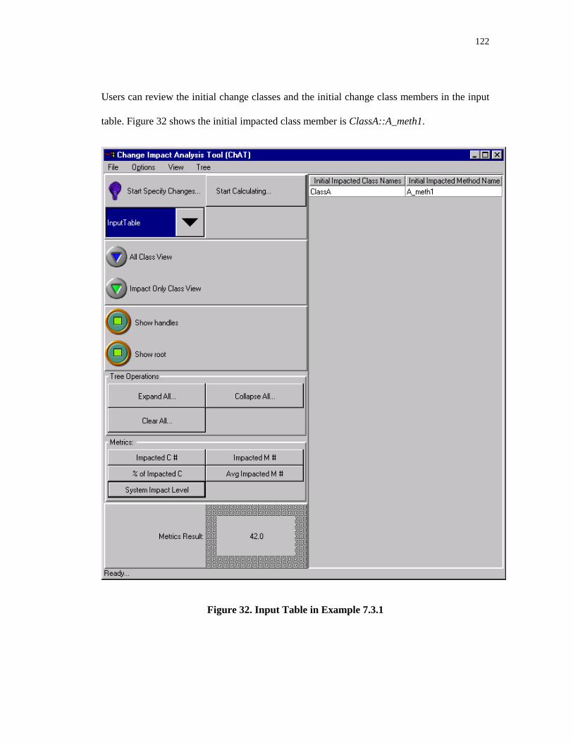
122
Users can review the initial change classes and the initial change class members in the input
table. Figure 32 shows the initial impacted class member is ClassA::A_meth1.
Figure 32. Input Table in Example 7.3.1

123
7.3.2 Change Propagation Inside a Class with Recursive Relationships
This section demonstrates how the algorithms handle recursive dependencies among the
members of the same class. ClassA (presented in the previous section) is modified to contain
a recursive (cyclic) dependency relationship among its members. Figure 33 shows the
recursive dependency relationship: A_meth1() references A_meth2(), A_meth2() references
A_meth3(), A_meth3() uses _A_field1, and _A_field1 is defined by A_meth1().
ClassA::meth_2()
ClassA::meth_1()
ClassA::meth_3()
ClassA::_field_1
Figure 33. The recursive dependency in Example 7.3.2
When _A_field1 is specified to be changed, it will impact A_meth2(), A_meth3() and
_A_field1. A change to any member in this dependency cycle could potentially impact all
other members. Figure 34 through Figure 37 show the yielded results when _A_field1 in
ClassA is changed.
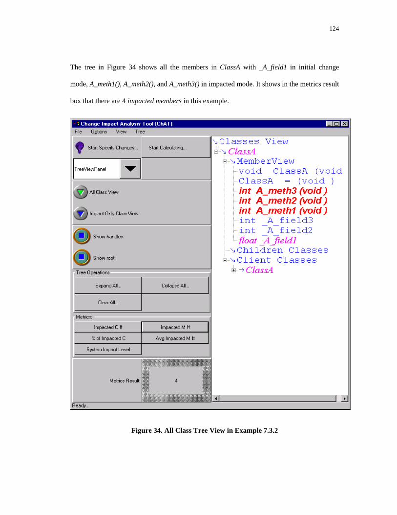
124
The tree in Figure 34 shows all the members in ClassA with _A_field1 in initial change
mode, A_meth1(), A_meth2(), and A_meth3() in impacted mode. It shows in the metrics result
box that there are 4 impacted members in this example.
Figure 34. All Class Tree View in Example 7.3.2

125
Figure 35, the impact only class view, displays only the impacted classes and their impacted
class members with _A_field1 in initial change mode, A_meth1(), A_meth2(), and A_meth3()
in impacted mode, and other not impacted members in clean mode. Its metrics result box
shows that the average impacted method numbers in this example is 0.5, which means half
the class members are impacted by the proposed change.
Figure 35. Impact Only Tree View in Example 7.3.2

126
Figure 36, the impact table, displays the impacted classes and their impacted class members
in a table. The table shows that ClassA::A_meth3(), ClassA::A_meth2(), ClassA A_meth1(),
and ClassA::_A_field1 are impacted, and their impact level are 35, 24, 12, and 3. The metrics
result box indicates that the system level impact is 74.
Figure 36. Impact Table of Example 7.3.2

127
Figure 37, the class impact table, shows the impacted classes and the related class level
change impact metrics. The table lists ClassA as the impacted class. ClassA’s number of
impacted members is 4, the average number of impacted member is 0.5, and the class impact
level is 74. The metrics result box shows the system impact level is 74. Because ClassA is
the only class in this example, the system impact level is equal to the class impact level of
ClassA.
Figure 37. Class Impact Table of Example 7.3.2

128
Users can review the initial change classes and the initial change class members in the input
table. Figure 38 shows the initial impacted class member is ClassA::_A_field1
Figure 38. Input Table in Example 7.3.2

129
7.3.3 Change Propagation among Use and Containment Relationships
This section exhibits how ChAT handles use and containment relationships. The header files
are show in Figure 39, and Figure 40 shows the class diagram of this example.
/* Example to test the propagation among use and containment relationships */
class ClassA {
public:
void A_meth1() { … A_meth2(); … _A_bclass->B_meth1(); … }
int A_meth2();
int A_meth3();
private:
ClassB* _A_bclass;
};
class ClassB {
public:
int B_meth1(ClassD& d, ClassC* c) {
int x;
if (c->C_meth1())
x = d.D_meth1();
….
}
int B_meth2(ClassD& d) { …; d.D_meth2(); … }
int B_meth3(ClassC& c) {…; c.C_meth2(); … }
};
class ClassC {
public:
int C_meth1(ClassA& aparam) { … aparam.A_meth2(); … }
int C_meth2();
};
class ClassD {
public:
int D_meth1();
private:
int D_field1;
};
Figure 39. Example 7.3.3 header files
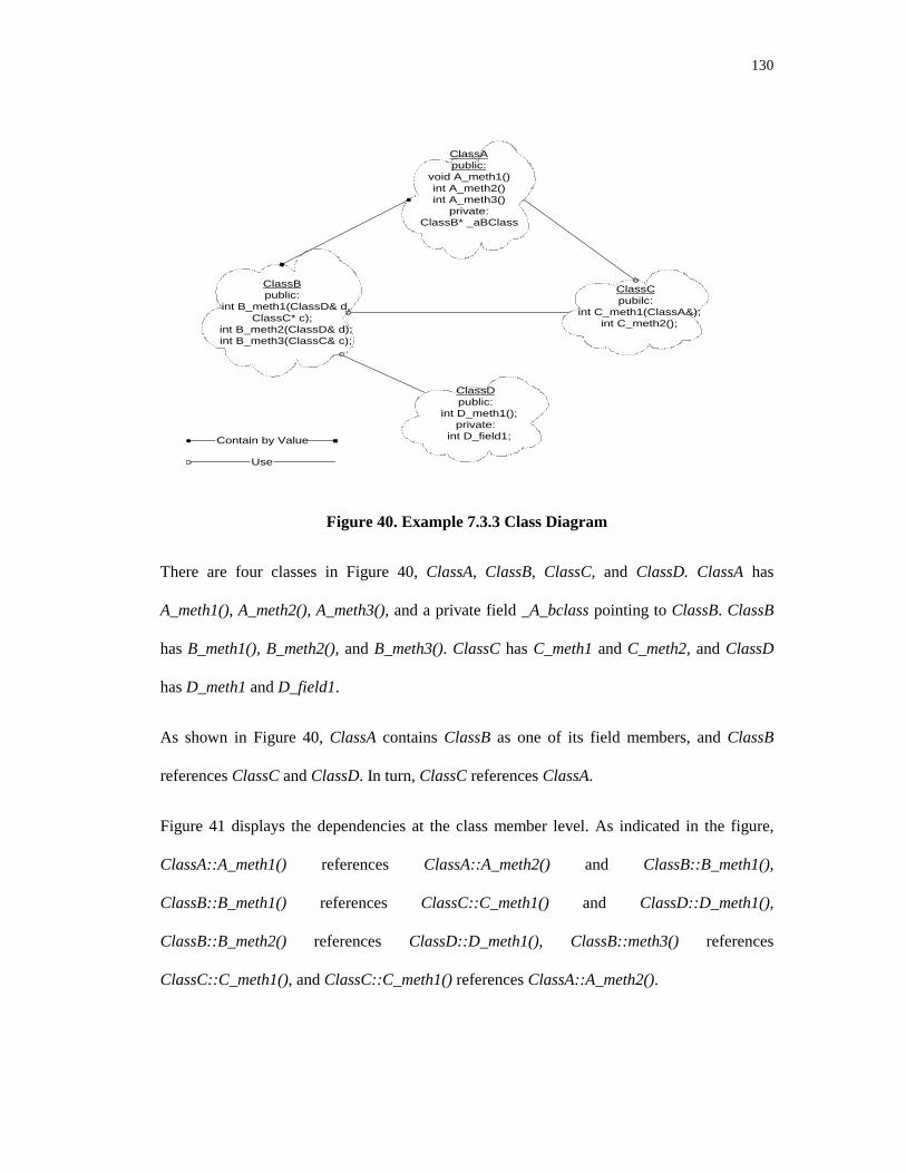
130
ClassApublic:
void A_meth1()int A_meth2()int A_meth3()
private:ClassB* _aBClass
ClassBpublic:
int B_meth1(ClassD& d,ClassC* c);
int B_meth2(ClassD& d); int B_meth3(ClassC& c);
ClassCpubilc:
int C_meth1(ClassA&); int C_meth2();
ClassDpublic:
int D_meth1();private:
int D_field1;Contain by Value
Use
Figure 40. Example 7.3.3 Class Diagram
There are four classes in Figure 40, ClassA, ClassB, ClassC, and ClassD. ClassA has
A_meth1(), A_meth2(), A_meth3(), and a private field _A_bclass pointing to ClassB. ClassB
has B_meth1(), B_meth2(), and B_meth3(). ClassC has C_meth1 and C_meth2, and ClassD
has D_meth1 and D_field1.
As shown in Figure 40, ClassA contains ClassB as one of its field members, and ClassB
references ClassC and ClassD. In turn, ClassC references ClassA.
Figure 41 displays the dependencies at the class member level. As indicated in the figure,
ClassA::A_meth1() references ClassA::A_meth2() and ClassB::B_meth1(),
ClassB::B_meth1() references ClassC::C_meth1() and ClassD::D_meth1(),
ClassB::B_meth2() references ClassD::D_meth1(), ClassB::meth3() references
ClassC::C_meth1(), and ClassC::C_meth1() references ClassA::A_meth2().
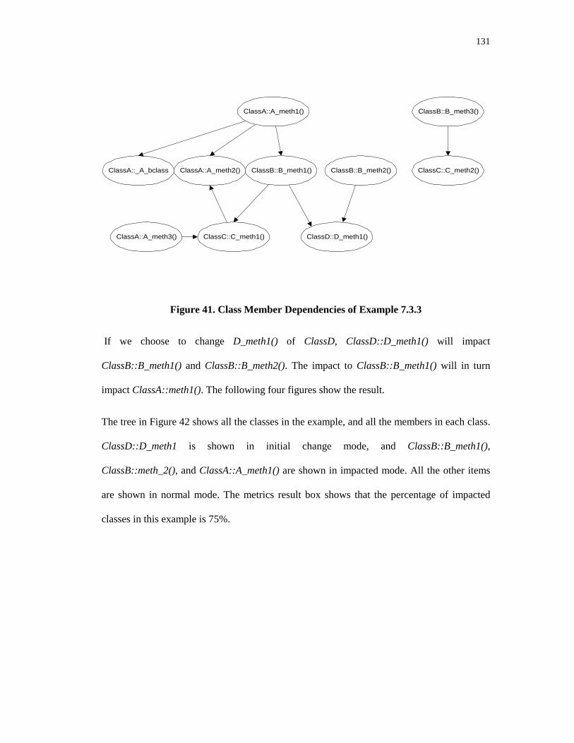
131
ClassA::_A_bclass
ClassA::A_meth1()
ClassC::C_meth1()
ClassB::B_meth1()ClassA::A_meth2() ClassB::B_meth2()
ClassD::D_meth1()ClassA::A_meth3()
ClassB::B_meth3()
ClassC::C_meth2()
Figure 41. Class Member Dependencies of Example 7.3.3
If we choose to change D_meth1() of ClassD, ClassD::D_meth1() will impact
ClassB::B_meth1() and ClassB::B_meth2(). The impact to ClassB::B_meth1() will in turn
impact ClassA::meth1(). The following four figures show the result.
The tree in Figure 42 shows all the classes in the example, and all the members in each class.
ClassD::D_meth1 is shown in initial change mode, and ClassB::B_meth1(),
ClassB::meth_2(), and ClassA::A_meth1() are shown in impacted mode. All the other items
are shown in normal mode. The metrics result box shows that the percentage of impacted
classes in this example is 75%.

132
Figure 42. All Class Tree View of Example 7.3.3

133
The tree in Figure 43 shows only the impacted classes and their impacted members.
ClassD::D_meth1 is shown in initial change mode, and ClassA::A_meth1(),
ClassB::B_meth1() and ClassB::meth_2() are shown in impacted mode. The metrics result
box shows that the number of impacted classes in this example is 3. ClassC is not shown in
this tree since it is not impacted.
Figure 43. Impact Only Tree View of Example 7.3.3

134
Figure 44, the impact table, displays the impacted classes and their impacted class members
in a table. The table shows that ClassD::D_meth1(), ClassB::B_meth2(), ClassB::B_meth1(),
and ClassA_meth1 are impacted, and their impact level are 45, 67, 45, and 26. The metrics
result shows that the number of impacted members in this example is 4.
Figure 44. Impact Table of Example 7.3.3

135
Figure 45, the class impact table, shows the impacted classes and the related class level
change impact metrics. The figure shows ClassD, ClassB and ClassA are the impacted
classes. The class related metrics, such as number of impacted members in each class, the
average number of impacted members, the class impact level are listed in the table. The
metrics result box shows that the average number of impacted members is 0.211.
Figure 45. Class Impact Table of Example 7.3.3

136
Users can review the initial change classes and the initial change class members in the input
table. Figure 46 shows the initial impacted class member is ClassD::D_meth1. The metrics
result box in this figure shows that the system impacted level caused by ClassD::D_meth1 is
183.
Figure 46. Input Table of Example 7.3.3
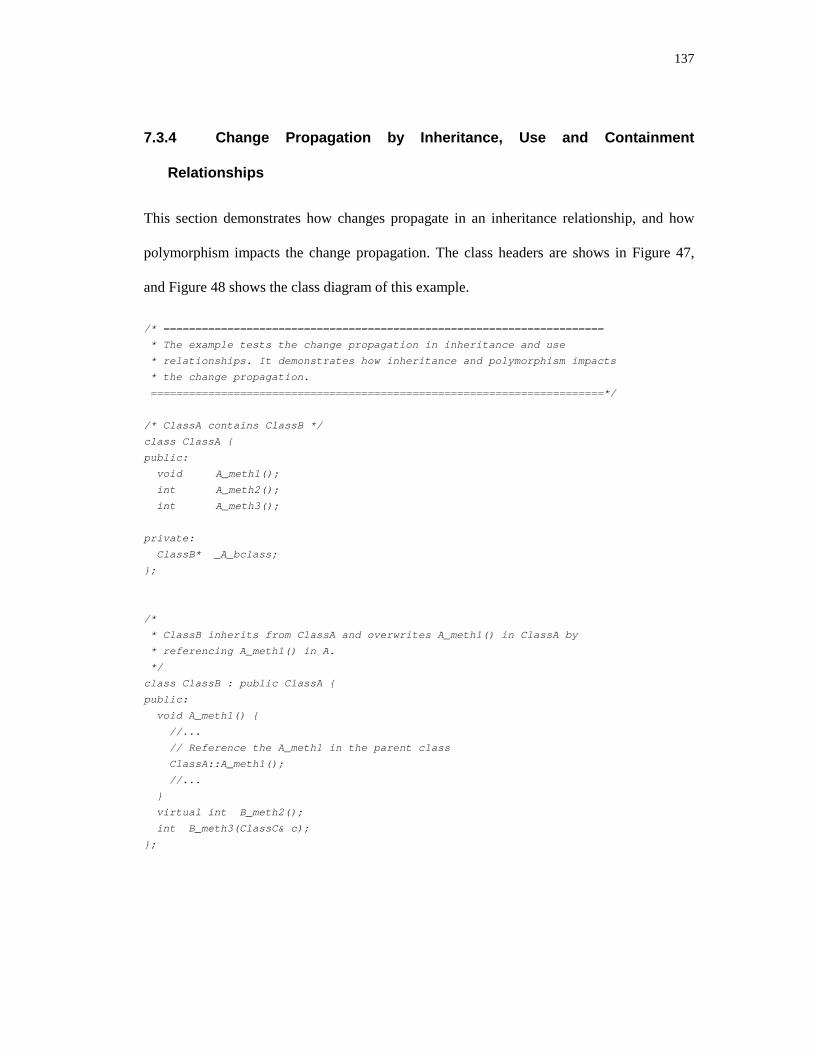
137
7.3.4 Change Propagation by Inheritance, Use and Containment
Relationships
This section demonstrates how changes propagate in an inheritance relationship, and how
polymorphism impacts the change propagation. The class headers are shows in Figure 47,
and Figure 48 shows the class diagram of this example.
/* =====================================================================
* The example tests the change propagation in inheritance and use
* relationships. It demonstrates how inheritance and polymorphism impacts
* the change propagation.
=======================================================================*/
/* ClassA contains ClassB */
class ClassA {
public:
void A_meth1();
int A_meth2();
int A_meth3();
private:
ClassB* _A_bclass;
};
/*
* ClassB inherits from ClassA and overwrites A_meth1() in ClassA by
* referencing A_meth1() in A.
*/
class ClassB : public ClassA {
public:
void A_meth1() {
//...
// Reference the A_meth1 in the parent class
ClassA::A_meth1();
//...
}
virtual int B_meth2();
int B_meth3(ClassC& c);
};

138
/*
* ClassC inherits ClassA, but does not overwrite any methods in ClassA,
* C_meth2 references ClassB’s virtual function B_meth2 ().
*/
class ClassC : public ClassA {
public:
int C_meth1(ClassA& aparam);
int C_meth2(ClassB& b) {
//...
b.B_meth2();
//...
}
};
/*
* ClassD inherits from ClassB, and overwrites its virtual function B_meth2().
*/
class ClassD : public ClassB {
public:
int D_meth1();
virtual int B_meth2() {
//...
ClassB::B_meth2();
//...
}
private:
int D_field1;
};
/*
* ClassE inherits ClassB, and overwrites the virtual function B_meth2().
*/
class ClassE : public ClassB {
public:
int E_meth1();
virtual int B_meth2() {
//...
ClassB::B_meth2();
//...
}
private:
int E_field1;
};
Figure 47. Inheritance Relationship Sample Code

139
ClassApublic:
void A_meth1();int A_meth2();int A_meth3();
private:ClassB* _aBClass;
ClassBpublic:
void A_meth1(); int B_meth1();
virtual int B_meth2(); int B_meth3(ClassC& c);
ClassCpubilc:
int C_meth1(ClassA&);int C_meth2(ClassB&);
ClassDpublic:
virtual int B_meth2(); int D_meth1();
private: int D_field1;
Inherited from
Use
ClassEpublic:
virtual int B_meth2(); int E_meth1();
private: int E_field1;
Figure 48. Class Diagram of Example 7.3.4
Figure 48 shows the relationship at the class level: ClassA is the parent of ClassB and
ClassC. ClassB is the parent of ClassD and ClassE. ClassC uses ClassB.
At the class member level, ClassB overwrites ClassA’s A_meth1() by reusing
ClassA::A_meth1()’s service. Any change in ClassA::A_meth1() will impact
ClassB::A_meth1(). Since A_meth1() is not virtual, changes in ClassB::A_meth1() will not
impact ClassA. ClassD and ClassE overwrite the virtual function B_meth2() of ClassB and
reuse ClassB::B_meth2()’s service. ClassC::C_meth2() uses ClassB::B_meth2(). Since
ClassD and ClassE are ClassB’s children and overwrite ClassB’s B_meth2(), a change to
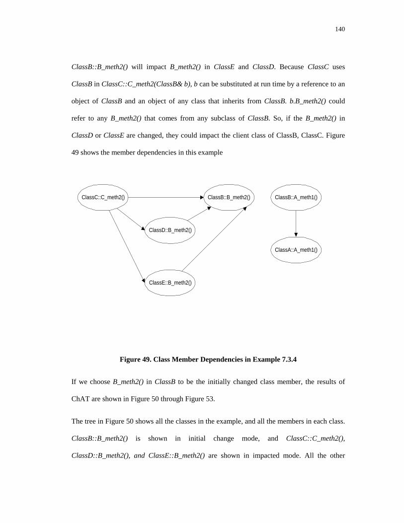
140
ClassB::B_meth2() will impact B_meth2() in ClassE and ClassD. Because ClassC uses
ClassB in ClassC::C_meth2(ClassB& b), b can be substituted at run time by a reference to an
object of ClassB and an object of any class that inherits from ClassB. b.B_meth2() could
refer to any B_meth2() that comes from any subclass of ClassB. So, if the B_meth2() in
ClassD or ClassE are changed, they could impact the client class of ClassB, ClassC. Figure
49 shows the member dependencies in this example
ClassC::C_meth2() ClassB::B_meth2()
ClassE::B_meth2()
ClassD::B_meth2()
ClassB::A_meth1()
ClassA::A_meth1()
Figure 49. Class Member Dependencies in Example 7.3.4
If we choose B_meth2() in ClassB to be the initially changed class member, the results of
ChAT are shown in Figure 50 through Figure 53.
The tree in Figure 50 shows all the classes in the example, and all the members in each class.
ClassB::B_meth2() is shown in initial change mode, and ClassC::C_meth2(),
ClassD::B_meth2(), and ClassE::B_meth2() are shown in impacted mode. All the other

141
items are shown in normal mode. The metrics result box shows that the number of impacted
classes in this example is 4.
Figure 50. All Class Tree View of Example 7.3.4

142
The tree in Figure 51 shows only the impacted classes and their impacted members in the
example. ClassB::B_meth2 is shown in initial change mode, while ClassC::C_meth2(),
ClassD::B_meth2() and ClassE::B_meth2() are shown in impacted mode. The metrics result
box shows that the number of impacted classes in this example is 4. ClassA is not shown in
this tree since it is not impacted.
Figure 51. Impact Only Class Tree View in Example 7.3.4

143
Figure 52, the impact table, displays the impacted classes and their impacted class members
in a table. The table shows that ClassE::B_meth2(), ClassD::B_meth2(), ClassC::C_meth2(),
and ClassB::B_meth2() are impacted, and their impact level are 56, 23, 34, and 34. The
metrics result shows that the percentage of impacted members in this example is 80%.
Figure 52. Impact Table of Example 7.3.4

144
Figure 53, the class impact table, shows the impacted classes and the related class level
change impact metrics. The figure shows ClassE, ClassD, ClassC and ClassB are the
impacted classes. The class related metrics, such as number of impacted members, the
average number of impacted members, and the class impact level are listed in the table. The
metrics result box shows the system impact level is 147.
Figure 53. Class Impact Table of Example 7.3.4

145
Users can review the initial change classes and the initial change class members in the input
table. Figure 54 shows that the initial impacted class member is ClassD::D_meth1. The
metrics result box in this figure shows that the average number of impact member is 0.16.
Figure 54. Input Table of Example 7.3.4

146
7.4 A Case Study From a Commercial Industry Environment
To demonstrate realistic applicability of this tool, we applied ChAT to LCC International’s
Golf product, a wireless frequency planning tool. Document, notification, and graphic are
three major modules in Golf. The notification module, with 20 classes and 2,624 lines of
code, provides a system wide mechanism for the propagation of information among classes
and functions. The document module, with 48 classes and 10,000 lines of code, provides
basic functionality to manage multiple layers of data. The graphic module, with 63 classes
and 16,884 lines of code, provides the drawing capability.
Users can view more than one kind of data at the same time. For example, terrain elevations
are drawn as one layer of data to express the height of the terrain in the covered area, while
highway layer is the layer to draw highways in that area. Users can overlay the highway on
top of terrain. There are other kinds of data such as building data, morphology data, and the
signal strength covering that area etc. Users can add more layers to the view, remove layers
from the view, and shuffle the order of layers. Whenever an action is triggered by the users,
the document module will use the notification module to send out the corresponding
notification to all listeners that are registered for that kind of action. All the listeners will do
their respective work after receiving the notification, such as change the user interface status
or update the graphic view. Instead of accessing the document directly, the graphic module is
one of its listeners. Whenever the graphic class gets a notification, it performs the drawing.
For example, when a user presses the load terrain button, Golf will create an icon to
represent the loaded terrain on the screen, and draw the terrain in different colors according
to their heights. When the load terrain button is pressed, instead of directly calling the icon
view object to create the icon and calling the graphic object to draw the terrain layer, the
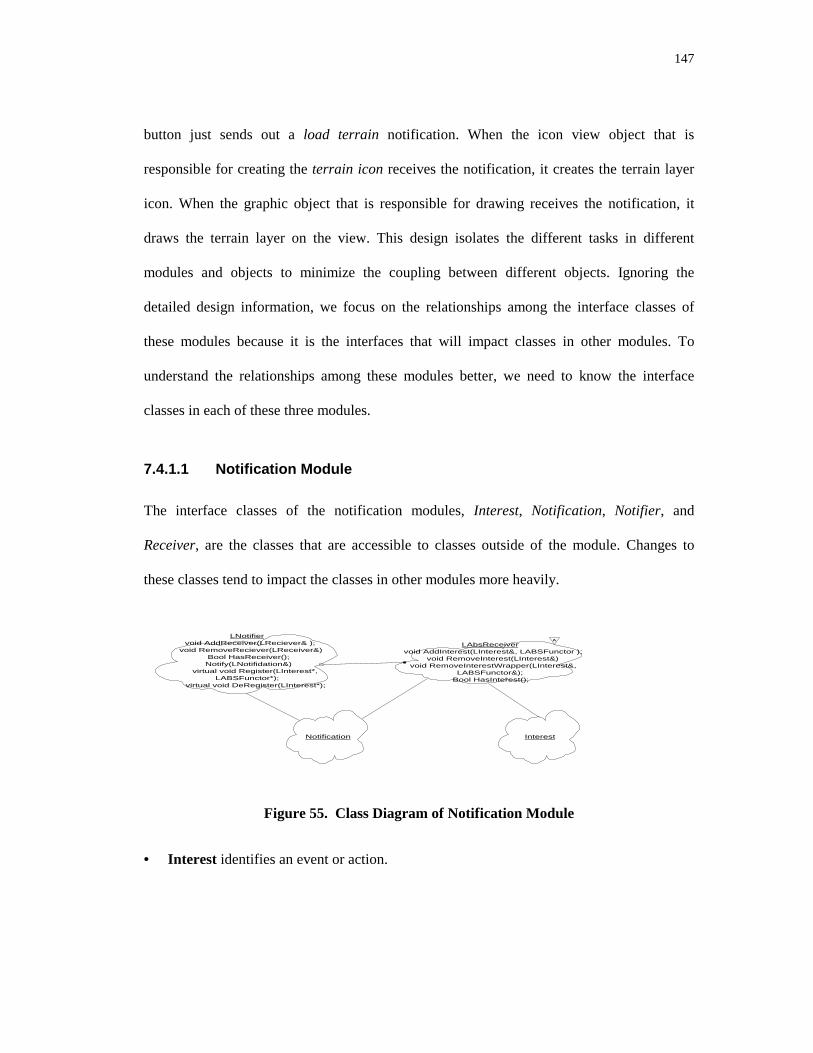
147
button just sends out a load terrain notification. When the icon view object that is
responsible for creating the terrain icon receives the notification, it creates the terrain layer
icon. When the graphic object that is responsible for drawing receives the notification, it
draws the terrain layer on the view. This design isolates the different tasks in different
modules and objects to minimize the coupling between different objects. Ignoring the
detailed design information, we focus on the relationships among the interface classes of
these modules because it is the interfaces that will impact classes in other modules. To
understand the relationships among these modules better, we need to know the interface
classes in each of these three modules.
7.4.1.1 Notification Module
The interface classes of the notification modules, Interest, Notification, Notifier, and
Receiver, are the classes that are accessible to classes outside of the module. Changes to
these classes tend to impact the classes in other modules more heavily.
LNotifiervoid AddReceiver(LReciever& );
void RemoveReciever(LReceiver&)Bool HasReceiver();Notify(LNotifidation&)
virtual void Register(LInterest*,LABSFunctor*);
virtual void DeRegister(LInterest*);
LAbsReceivervoid AddInterest(LInterest&, LABSFunctor );
void RemoveInterest(LInterest&)void RemoveInterestWrapper(LInterest&,
LABSFunctor&);Bool HasInterest();
A
InterestNotification
Figure 55. Class Diagram of Notification Module
• Interest identifies an event or action.

148
• Notification conveys news of actions to receivers. When a sender wants to propagate an
action, it uses the appropriate interest, and possibly additional specific data, to create a
notification. Clients use notifications to communicate with each other.
• Notifier is the action dispatcher. Senders use the notifier to send out notification to
receivers that have registered.
• Receivers are the action listeners, they get notified whenever the action they have
registered for happens.
7.4.1.2 Document Module
The interface classes of the document module are DocLayer, DocPage, and Document.
Document holds a list of DocPages. DocPage holds a list of DocLayer. Figure 56 displays
the class diagram of this module.
DocLayer DocPage
Document
Figure 56. Document Module Class Diagram

149
• A DocLayer is the super class of all concrete data layers, for example, terrain layer,
highway layer.
• A DocPage owns a queue of DocLayers, and is responsible for adding, removing, and
shuffling the order of these layers. Whenever a DocLayer is added, removed or shuffled, a
notification is sent.
• A Document holds a list of DocPages. It is responsible for adding and removing
document pages.
7.4.1.3 The Graphic Module
Receiver
GraphicLayer void handleLayerAdded (LNotification&);
void handleLayerRemoved (LNotification&); void handlePageAdded (LNotification&);
void handlePageRemoved (LNotification&); void handleLayerShuffled (LNotification&)};
Figure 57. Class Diagram of Graphic Module
The graphic module is responsible for the graphic viewing of the document layer. Class
GraphicLayer is a sub-class of Receiver. Whenever the document module performs an
action, the notifier will invoke the corresponding handler from GraphicLayer.
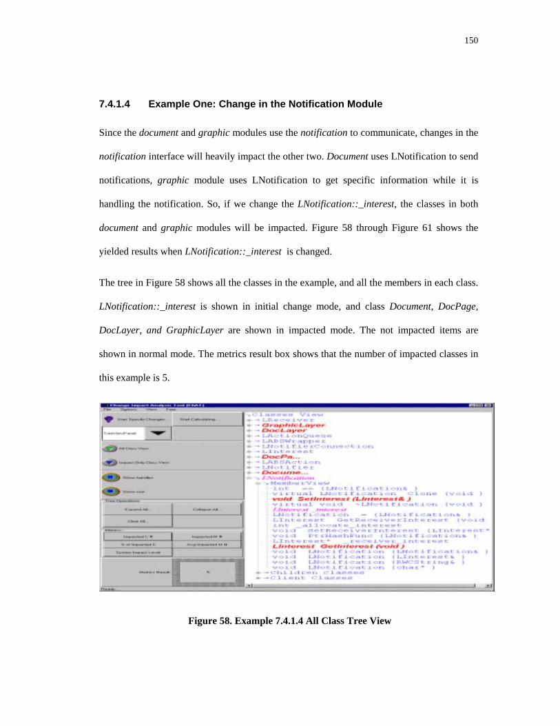
150
7.4.1.4 Example One: Change in the Notification Module
Since the document and graphic modules use the notification to communicate, changes in the
notification interface will heavily impact the other two. Document uses LNotification to send
notifications, graphic module uses LNotification to get specific information while it is
handling the notification. So, if we change the LNotification::_interest, the classes in both
document and graphic modules will be impacted. Figure 58 through Figure 61 shows the
yielded results when LNotification::_interest is changed.
The tree in Figure 58 shows all the classes in the example, and all the members in each class.
LNotification::_interest is shown in initial change mode, and class Document, DocPage,
DocLayer, and GraphicLayer are shown in impacted mode. The not impacted items are
shown in normal mode. The metrics result box shows that the number of impacted classes in
this example is 5.
Figure 58. Example 7.4.1.4 All Class Tree View
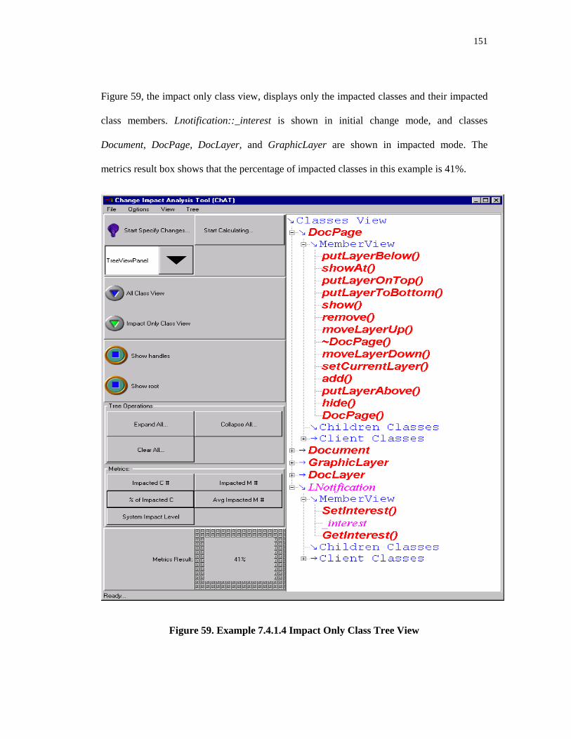
151
Figure 59, the impact only class view, displays only the impacted classes and their impacted
class members. Lnotification::_interest is shown in initial change mode, and classes
Document, DocPage, DocLayer, and GraphicLayer are shown in impacted mode. The
metrics result box shows that the percentage of impacted classes in this example is 41%.
Figure 59. Example 7.4.1.4 Impact Only Class Tree View

152
Figure 60, the impact table, displays the impacted classes and their impacted class members
in a table. Each line contains the impacted class name, impacted member name, and the
impact level of that impacted member. The metrics result box shows that the number of
impacted members is 33.
Figure 60. Example 7.4.1.4 Member Impact Table
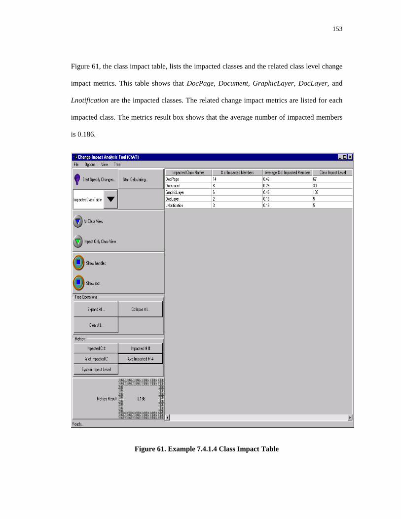
153
Figure 61, the class impact table, lists the impacted classes and the related class level change
impact metrics. This table shows that DocPage, Document, GraphicLayer, DocLayer, and
Lnotification are the impacted classes. The related change impact metrics are listed for each
impacted class. The metrics result box shows that the average number of impacted members
is 0.186.
Figure 61. Example 7.4.1.4 Class Impact Table

154
Users can review the initial change classes and the initial change class members in the input
table. Figure 62 shows that the initial impacted class member is Lnotification::_interest. The
metrics result box shows that the system level impact caused by the LNotification::_interest
change is 243.
Figure 62. Input Table of Example 7.4.1.4
155
7.4.1.5 Example Two: Change in the Document Module
Since the document holds the data the graphic layer needs, we might think there are a lot of
dependencies between these two modules. But, since these two modules communicate
through the notification, the coupling between these two modules is very weak. For example,
when AddPage() in Document is changed, the following figures show that there is no effect
on the graphic and notification modules. It means whenever the classes in the document
module are changed, the classes in the graphic module are not impacted. Conversely,
whenever the classes in the graphic module are changed, the classes in the document module
are not impacted. This approach decreases the coupling among the modules, and makes the
system easy to expand and maintain.
The tree in Figure 63 shows all the classes in the example, and all the members in each class.
Document::AddPage(DocPage&) is shown in initial change mode. Since DocPage’s
constructor uses the service of Document::AddPage(DocPage&), DocPage::DocPage() is
impacted. So, DocPage class is shown in impacted mode. Other not impacted items are
shown in normal mode. The metrics result box shows that the number of impacted classes in
this example is 2.
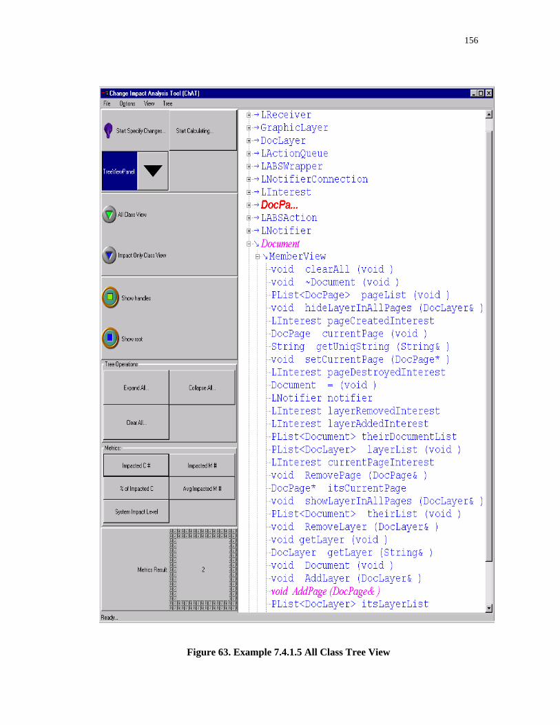
156
Figure 63. Example 7.4.1.5 All Class Tree View

157
Figure 64, the impact only class view, displays only the impacted classes and their impacted class
members. Document::AddPage() is shown in initial change mode, and class DocPage is shown in
impacted mode. Other not impacted items are not shown in the figure. The metrics result box
shows that the percentage of impacted classes in this example is only 16%.
Figure 64. Example 7.4.1.5 Impact Only Class Tree View
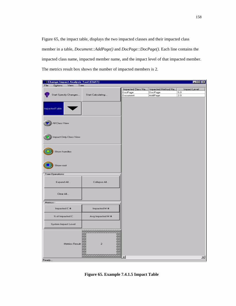
158
Figure 65, the impact table, displays the two impacted classes and their impacted class
member in a table, Document::AddPage() and DocPage::DocPage(). Each line contains the
impacted class name, impacted member name, and the impact level of that impacted member.
The metrics result box shows the number of impacted members is 2.
Figure 65. Example 7.4.1.5 Impact Table

159
Figure 66, the class impact table, lists the impacted classes and the related class level change
impact metrics. This table shows that DocPage and Document are the impacted classes. The
metrics result box shows the average number of impacted member is 0.011.
Figure 66. Example 7.4.1.5 Class Impact Table

160
Figure 67 shows the input table of this example.
Figure 67. The Input Table of Example 7.4.1.5

161
8 CONTRIBUTIONS AND FUTURE WORK
This dissertation has presented four major new results. First, a new analysis technique for
object-oriented software has been defined and developed. The research led to the creation of
a set of new concepts including the object-oriented data dependency graphs object-oriented
intra-method data dependency graph, object-oriented inter-method data dependency graph,
and object-oriented system dependency graph. We classified the different dependency
relationships in object-oriented software, and the different types of changes that could be
applied to object-oriented software. This analysis technique also includes a set of algorithms
to calculate the change impact according to the criteria that users specify. Second, this
analysis technique has been used to address the problem of change impact analysis for
object-oriented software. Third, a set of metrics has been defined for object-oriented
software that can be used to quantitatively measure the object-oriented change impact.
Fourth, a proof-of-concept tool has been implemented and used to demonstrate the practical
feasibility of this approach on industrial software.
By using the technology developed in this research to identify potential impacts before
making a change, we can greatly reduce the risks of embarking on a costly change because
the later the problem is discovered the more it costs. This technology can provide visibility
into the potential effects of changes before the changes are implemented, and identify the
consequences or ripple effects of proposed software changes. As a result, it can help software
developers and maintainers plan changes, make changes more accurately, accommodate

162
certain types of software changes, and trace through the effects of changes. They can also use
it to evaluate the appropriateness of a proposed modification. If a proposed change has the
possibility of impacting large, disjoint sections of a program, the change might need to be re-
examined to determine whether a safer change is possible. Managers can use this technique
to run "what if" analyses on different change proposals, and choose the one that is most cost
effective. Software developers can use this technique to indicate the vulnerability of critical
sections of code. If a module that provides critical functionality is dependent on many
different parts of a program, its functionality is susceptible to changes made in these parts.
Software testers can use it to find which areas are impacted by the changes, enabling them to
focus only on those areas and still feel confident about the quality of the software.
This research also creates a set of object-oriented change impact analysis metrics that can
help software maintainers to quantitatively measure the software in regards to its
susceptibility to change. We have not seen any other concrete metrics for measuring change
impacts of object-oriented software.
We also explored the inference approach to solve the change impact analysis problem. The
impact calculating algorithms are expressed in data base deductive rules. The advantage of
this approach is that we can take advantage of the deductive capability of logic database to
let users compose their own questions to the system.
8.1 Future Work
One aspect of this research that needs to be refined is that of choosing the right constants for
the metrics developed in Chapter 0. A major undertaking would be to validate these metrics,
and explore how best to apply them to real-life software. The constants used in these metrics
are used to assign weights to different items expressing how much impact these items will

163
have to the software. We can assign the initial values to these constants according to the
characteristics of the items they applied to, the conduct various experiments to find the most
suited values.
We did not actually implement all the approaches studied in this research. For example, we
explored the inference approach and how to implement it using an inference tool called
Coral, but the prototype did not use this approach because of performance issues.
Another area to consider for further research involves analyzing software change impact
from the semantic perspective. The syntactic impact is calculated purely by information
extracted from the source code. This information includes the data flow, the control flow and
the calling hierarchy. Semantic knowledge consists of programming knowledge and domain
knowledge. Semantic knowledge is more difficult to derive and more difficult to verify
compared to syntactic knowledge because it is less concrete and tangible. We can extract
accurate syntactic information by parsing the software while the exact semantic information
such as the program’s behavior is harder to get.
As an example, using semantic analysis in software testing, debugging, and maintenance, one
is often interested in this question:
When can a change in the semantics of a program statement impact the execution behavior
of another statement?
This question is undecidable in general [PODG90]. Dependence analysis, like data flow
analysis, avoids problems of undecidability by trading precision for decidability. During
dependence analysis, programs are represented by def/use graphs, which contain limited
semantic information but are easy to analyze. Dependence analysis allows semantic
164
questions to be answered “approximately,” because a program’s dependencies partially
determine its semantic properties.
We could improve the semantic analysis by plugging in semantics checking instruments. The
results would be impacted by semantic information that can be controlled by users. For each
method, we would expect to use pre-condition, post-condition and axiom verifications.
PRE-CONDITION: Rule1 && Rule2…
Method1’s implementation
….
POST-CONDITION: Rule1 && Rule2…
AXIOMS: Rule…
PRE-CONDITION is used to describe under what certain condition this method will start its
operations. POST-CONDITION is used to describe what this method will deliver if PRE-
CONDITION is met, and the behavior of the method has to meet whatever is described in the
AXIOM rules.
If the signature of the method remains the same, changing the method’s implementation,
while keeping the PRE-CONDITION, POST-CONDITION, and AXIOM the same will not
impact this method’s clients. This approach has the potential to dramatically reduce the
extend of the impact that is calculated from syntactic information.
Another future research possibility is dynamic change impact analysis. Static impact is
calculated according to static information obtained at compile time. Dynamic impact is
calculated by executing the program. The change impact set calculated from static analysis
will be bigger than the one calculated from dynamic analysis. For example, a class in the
method’s signature can be substituted by any of its subclasses, but the information about

165
which subclass will be substituting that base class cannot be known until run time. We have
to approximate the result to count the effect of all its subclasses in static analysis. With this
information in hand, the dynamic change impact set only needs to consider the actual
subclass that is substituting the base class, So, the result set is smaller and more accurate, but
the dynamic change analysis set is limited to the corresponding input data at that execution.

166
APPENDIX A. OBJECT-ORIENTED CHANGE IMPACT RULES AND
FACTS
This section summaries the facts and rules used in Section 0.
ref (c1, m1, c2, m2) :- direct-ref(c1, m1, c2, m2).
ref (c1, m1, c3, m3) :- ref(c1, m1, c2, m2), direct_ref(c2, m2, c3, m3).
• Facts and rules that describes information inside the class
member(c, m) :- method (c, m)
member(c, n) :- data_field(c, n)
IFS(c, m) :- IFS(c, n), method(c, m), ref(c, m, c, n).
IFS(c, m) :- IDS(c, f), method(c, m) ref(c, m, c, f).
IDS(c d) :- IFS(c, n), data_field(c, d), ref(c, d, c, n).
IDS(c, d) :- IDS(c, x), data_field(c, d), ref(c, d, c, x).
• Rules and facts about inheritance
IFS(c, m) :- ICS(parent), children(parent, c), method(c, m), inherit(parent, m, c, m),
IFS(parent, m);
IFS(c, m) :- ICS(parent), children(parent, c), method(c, m), p-overwrite(parent, m, c, m),
IFS(parent, m);
IFS(c, m) :- ICS(parent), children(parent, c), method(c, m), ref(parent, x, c, m),
IDS(parent, x), public(parent, x).
IFS(c, m) :- ICS(parent), children(parent, c), method(c, m), ref(parent, x, c, m),
IDS(parent, x), protected(parent, x).
IFS(c, m) :- ICS(parent), children(parent, c), method(c, m), ref(parent, n, c, m),
IMS(parent, n), public(parent, n).
IFS(c, m) :- ICS (parent), children(parent, c), method(c, m), ref(parent, n, c, m),
IMS(parent, n), protected(parent, n).
IDS(c, f) :- ICS (parent), children(parent, c), data_field(c, f), ref(parent, x, c, f),
IFS(parent, x), public(parent, x).
IDS(c, f) :- ICS (parent), children(parent, c), data_field(c, f), ref(parent, x, c, f),
IFS(parent, x), protected(parent, x).
IDS(c, f) :- ICS (parent), children(parent, c), data_field(c, f), ref(parent, m, c, f),
IDS(parent, m), public(parent, m).
IDS(c, f) :- ICS (parent), children(parent, c), data_field(c, f), ref(parent, m, c, f),
IDS(parent, m), protected(parent, m).

167
• Rules and facts related to containment/use relationships
PIMS(c, m) :- IMS(c, m), public(c, m).
PIDS(c, f) :- IDS(c, f), public(c, f).
IFS(c, m) :- client (c0, c), method(c, m), ref(c0, n, c, m), PIFS(c0, n).
IFS(c, m) :- client (c0, c), method(c, m), ref(c0, f, c, m), PIDS(c0, f).
IDS(c, f) :- client (c0, c), data_field(c, f), ref(c0, n, c, f), PIFS(c0, n).
IDS(c, f) :- client (c0, c), data_field(c, f), ref(c0, x, c, f), PIDS(c0, x).
• Initialize impacted class set facts
ICS(c) :- IICS(c).
ICS(c) :- IFS(c, m).
ICS(c) :- IDS(c, f)

168
APPENDIX B. CLASS HEADERS OF TESTED MODULES
#ifndef INTEREST_H
#define INTEREST_H
//////////////////////////////////////////////////////////
// Linterest is the class used to expressed for the events
// intended to notify other classes
//
// Copyright (c) LCC, LLC
//
// June 96
// Li Li
#include <rw/cstring.h>
#include <stdlib.h>
class LInterest
{
public:
LInterest(const char* operation = 0);
LInterest(const RWCString& opStr);
LInterest(const LInterest& interest);
virtual ~LInterest();
public:
LInterest& operator = (const LInterest& interest);
int operator == (const LInterest& interest) const;
int operator != (const LInterest& interest) const;
const RWCString & GetOperation() const;
static unsigned PtrHashFunc(const LInterest & interest );
static unsigned ValHashFunc(const LInterest & interest );
protected:
RWCString _operation;
};
#endif // INTEREST_H
#ifndef _LRECEIVER_H
#define _LRECEIVER_H

169
#ifndef NOTIFICATION_H
#define NOTIFICATION_H
#include "Notification/Interest.h"
//////////////////////////////////////////////////////////
// Notification class header file
//
// Copyright (c) LCC, LLC
// Nov 96
// Li Li
class LNotification
{
public:
LNotification(const char* operation = 0);
LNotification(const RWCString& operation);
LNotification(const LInterest& interest);
virtual ~LNotification();
public:
int operator == (const LNotification& n) const;
// sub class need to overwrite the clone method.
// Because I cannot predict whether the notification object
// is a heap or stack object. When the client throw notification
// within notification, the notify action will be queued for later
// execution.
virtual LNotification* Clone() const = 0;
public:
const LInterest& GetInterest() const ;
void SetInterest(const LInterest& interest);
LInterest* GetReceiverInterest() const { return _receiver_interest; }
void SetReceiverInterest(LInterest* interest) { _receiver_interest = interest; }
static unsigned PtrHashFunc(const LNotification& notification);
protected:
LNotification(const LNotification& notification);
LNotification& operator = (const LNotification& n);
private:
int _allocate_interest;
LInterest _interest;
LInterest* _receiver_interest;
};
//--------------------------------------------------------------
// LDefaultNotification is the simplest notification that just

170
// overwrite the LNotificaiton’s Clone method. So, it can be
// instantiable.
class LDefaultNotification : public LNotification
{
public:
LDefaultNotification(const char* operation = 0);
LDefaultNotification(const RWCString& operation);
LDefaultNotification(const LInterest& interest);
virtual ~LDefaultNotification();
virtual LNotification* Clone() const;
protected:
LDefaultNotification (const LDefaultNotification& other);
};
class LBatchNotification : public LNotification
{
public:
LBatchNotification (const LInterest& interest) : LNotification(interest)
{
}
virtual LNotification* Clone() const {
return ( new LBatchNotification(*this) );
}
protected:
LBatchNotification (const LBatchNotification& other)
: LNotification(other)
{
}
};
#endif // NOTIFICATION_H
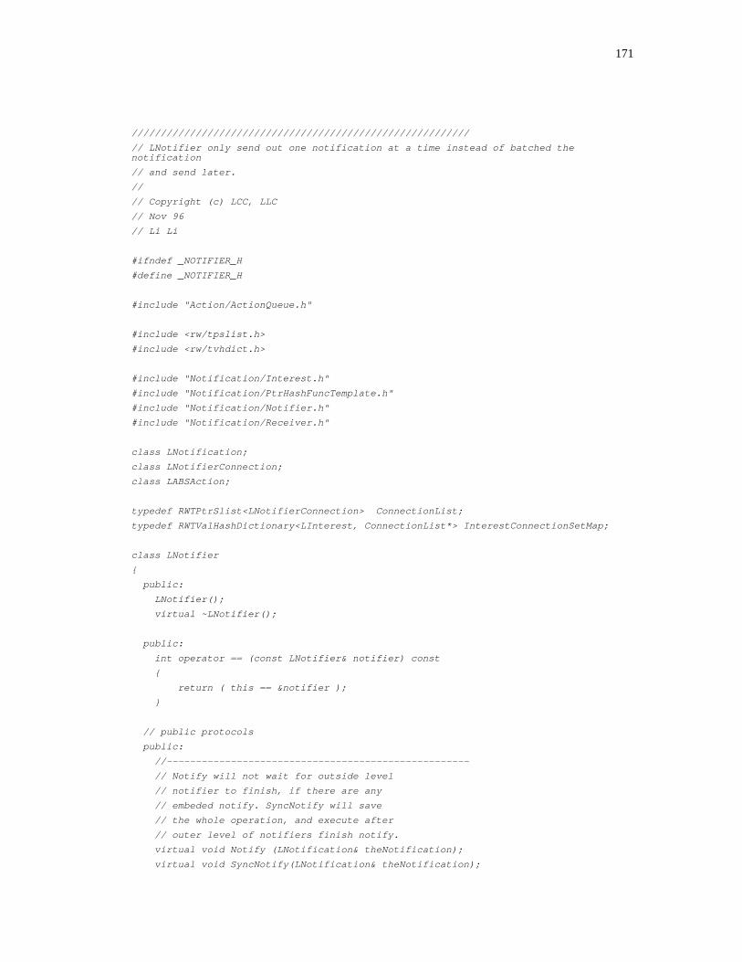
171
//////////////////////////////////////////////////////////
// LNotifier only send out one notification at a time instead of batched thenotification
// and send later.
//
// Copyright (c) LCC, LLC
// Nov 96
// Li Li
#ifndef _NOTIFIER_H
#define _NOTIFIER_H
#include "Action/ActionQueue.h"
#include <rw/tpslist.h>
#include <rw/tvhdict.h>
#include "Notification/Interest.h"
#include "Notification/PtrHashFuncTemplate.h"
#include "Notification/Notifier.h"
#include "Notification/Receiver.h"
class LNotification;
class LNotifierConnection;
class LABSAction;
typedef RWTPtrSlist<LNotifierConnection> ConnectionList;
typedef RWTValHashDictionary<LInterest, ConnectionList*> InterestConnectionSetMap;
class LNotifier
{
public:
LNotifier();
virtual ~LNotifier();
public:
int operator == (const LNotifier& notifier) const
{
return ( this == ¬ifier );
}
// public protocols
public:
//----------------------------------------------------
// Notify will not wait for outside level
// notifier to finish, if there are any
// embeded notify. SyncNotify will save
// the whole operation, and execute after
// outer level of notifiers finish notify.
virtual void Notify (LNotification& theNotification);
virtual void SyncNotify(LNotification& theNotification);
172
virtual void BeginNotification() {}
virtual void EndNotification() {}
virtual int IsNotifyLocked() { return (_notify_lock); }
public:
virtual void AddReceiver(LReceiver& receiver);
virtual void RemoveReceiver(LReceiver& receiver);
virtual int HasReceiver(const LReceiver& receiver) const ;
public:
//----------------------------------------------------------
// The Interface here applies to the classes that are not
// LReceiver and still want to register for notification.
// It is caller’s responsibility to remember to DeRegister
// the interest when the interest is not longer needed.
//----------------------------------------------------
// Register interest and function
virtual void Register(const LInterest&, const LABSWrapper&);
//----------------------------------------------------
// Deregister all the wrapper associated with the interest
virtual void DeRegister(const LInterest&);
//----------------------------------------------------
// Deregister the specified the interest and wrapper
virtual void DeRegisterInterestWrapper(const LInterest&, const LABSWrapper&);
public:
//------------------------------------------------------------
// Convenient methods for different users
virtual void RemoveInterestFromAllReceivers(const LInterest&);
public:
//=============================================================
// public methods for implementation purpose
virtual void AddConnection(LNotifierConnection* connection);
virtual void RemoveConnection(LNotifierConnection* connection);
virtual void AddInterestConnection(const LInterest& interest,
LNotifierConnection* connection);
virtual void RemoveInterestConnection(const LInterest& interest,
LNotifierConnection* connection);
void AddWaitingAction(LABSAction* action);
void RemoveWaitingAction(LABSAction* action);
void DoNotify (LNotification& theNotification);
173
private:
virtual void ClearAllReceivers();
virtual void ClearConnectionReceiver(LNotifierConnection* con);
void DumpConnectionInterest();
private:
LReceiver _receiver_agent; // used to register member function
// for classes that is not a receiver
// and register for static and global functions
InterestConnectionSetMap _interest_connectionset_map;
int _notify_lock; // set to 1 if notifer is notifying
// when notifier is notifying, all
// actions comes in will be put to
// _action_waiting_list.
LActionQueue _action_waiting_queue;
};
#endif

174
//////////////////////////////////////////////////////////
// Receiver class header
//
// Copyright (c) LCC, LLC
// Nov 96
// Li Li
#include <rw/tpslist.h>
class LInterest;
class LNotifier;
class LNotifierConnection;
class LABSWrapper;
class LABSAction;
typedef RWTPtrSlist<LNotifier> NotifierList;
class LReceiver {
public:
LReceiver(LNotifier* notifier);
LReceiver();
virtual ~LReceiver();
public:
//=========================================================================
// public interface of receivers
// add interest to receiver, this will not take effect
// until notifier Add this receiver to itself using AddReceiver
// Note: I forgot whey LABSWrapper takes a pointer instead of reference. Li
// Add Interest and Wrapper
virtual void AddInterest(const LInterest& interest,
const LABSWrapper& wrapper );
// Remove all wrappers associated with the interest from receiver
virtual void RemoveInterest(const LInterest& interest);
// Remove the specified interest and wrapper from receiver
virtual void RemoveInterestWrapper(const LInterest& interest,
const LABSWrapper& wrapper);
// Remove all interest of the receiver
virtual void RemoveAllInterests();
public:
//===================================================================
// implementation interface; used by other classes in the
// framework, but not for the user.
LNotifier* GetActiveNotifier();
virtual int IsNotifierAttached(const LNotifier* notifier) const ;
175
virtual void AttachNotifier(LNotifier* notifier);
virtual void DetachNotifier(LNotifier* notifier);
virtual void DeRegisterItSelfFromAllNotifiers();
virtual void RegisterReceiverToNotifier(LNotifier* notifier);
virtual void DeRegisterItSelfFromNotifier(LNotifier* notifier);
private:
// implementation interface of receiver
void ActivateNotifier(LNotifier* notifier);
void AddActionToRegisteredNotifiers(LABSAction* action);
private:
// notifier list behave like a stack, the item added last
// is at first, and become the current active one.
NotifierList* _notifier_list;
LNotifierConnection* _connection;
};
#endif

176
#ifndef DocLayer_H
#define DocLayer_H
///////////////////////////////////////////////////////////////////////
// The DocLayer header file.
//
// Copyright (c) LCC, LLC
// April 96
// Olivier Jojic
///////////////////////////////////////
// Import Section
#include <Tools/Port.h>
#include <Tools/String.h>
#include <Tools/PList.h>
#include <Tools/Object.h>
#include <Notification/Notification.h>
#include <Notification/Interest.h>
class Document;
///////////////////////////////////////
// The DocLayer abstract class
//
// A layer is a (sharable) part of a document.
class DocLayer
: public Object
{
public:
//Calls the destructor internally
virtual void destroy ();
//----------------------------------
// The document owner of this layer
Document& document;
//------------------------------------------
// Name and description of this layer.
const String name;
String description;
//---------------------------------------------
// Notifications
//
// All notifications are generated by concrete subclasses.
// (notifications are sent to all documents that have a
// reference to this layer)
// The concrete notification is layer dependent.
//
// To register a receiver, use the notifier of the document.

177
//
// Warning: the interests below are only valid for THIS layer,
// ie, the registered receivers will only get notified when
// THIS layer changes (for other layer instances use their own interests).
const LInterest dataAddedInterest;
const LInterest dataRemovedInterest;
const LInterest dataChangedInterest;
protected:
DocLayer (Document&, const String& name);
virtual ~DocLayer ();
};
#endif

178
#ifndef DocPage_H
#define DocPage_H
#include <Tools/Port.h>
#include <Tools/PList.h>
#include <Tools/Object.h>
#include <Notification/Notification.h>
#include <Notification/Interest.h>
#include <DocLayers/Document.h>
class DocLayer;
////////////////////////////////////
// The DocPage final class.
//
// A page is a part of a document and has a stack of layers.
// The layers must belong to the document.
class DocPage
: public VObject
{
public:
DocPage (Document&);
~DocPage ();
Document& document;
// The first layer in the list is the top layer.
// The last layer in the list is the bottom layer.
const PList<DocLayer>& layerList () const { return itsLayerList; }
//Adding/removing a layer
// During the call of the "add()" method, if the layer does
// not belong to the Document of this page, it is automatically added.
void add (DocLayer&);
void remove (DocLayer&);
//Show/hide
//A switch to/from shown/hidden sends the LayerNotification
//for the visibility change interest.
void show (DocLayer&);
void hide (DocLayer&);
bool isHidden (DocLayer& layer) {
return (itsHiddenLayers.has (layer)) ? true : false;
}
// These send a ‘ShuffleNotification’
void moveLayerUp (DocLayer&);
void moveLayerDown (DocLayer&);
179
void putLayerOnTop (DocLayer&);
void putLayerToBottom (DocLayer&);
void putLayerAbove (DocLayer& aLayer, DocLayer& aTarget);
void putLayerBelow (DocLayer& aLayer, DocLayer& aTarget);
DocLayer* currentLayer () const { return itsCurrentLayer; }
void setCurrentLayer (DocLayer*);
// Notifications
// ---------------------------------------------
// (uses the notifier of the Document)
// The "instance level" interests are only valid for THIS page,
// ie, the registered receivers will only get notified when
// this page changes.
// The "class level" interests are valid for ANY page.
// (It’s normaly a bad idea for a receiver to register for both the
// instance level and for the class level interest).
const LInterest currentLayerInterest;
const LInterest layerAddedInterest;
const LInterest layerRemovedInterest;
const LInterest layerShuffledInterest;
const LInterest layerVisibilityInterest;
static const LInterest currentLayerClassInterest;
static const LInterest layerAddedClassInterest;
static const LInterest layerRemovedClassInterest;
static const LInterest layerShuffledClassInterest;
static const LInterest layerVisibilityClassInterest;
// Notification sent when the current layer changes
class CurrentLayerNotification : public Document::PageNotification {
public:
DocLayer* const previousCurrentLayer;
DocLayer* const currentLayer;
private:
CurrentLayerNotification (DocPage& thePage,
const LInterest theInterest,
DocLayer* thePreviousCurrentLayer,
DocLayer* theCurrentLayer)
: Document::PageNotification (document, theInterest, thePage)
, previousCurrentLayer (thePreviousCurrentLayer)
, currentLayer (theCurrentLayer)
{}
friend class DocPage;
};

180
// Notification sent when a layer is shown or hidden
class LayerNotification : public Document::PageNotification {
public:
DocLayer& layer;
int index;
protected:
LayerNotification (DocPage& thePage,
const LInterest& theInterest,
DocLayer& theLayer,
int theIndex)
: Document::PageNotification (thePage.document, theInterest, thePage)
, layer (theLayer)
, index (theIndex)
{}
friend class DocPage;
};
// Notification sent when layers are shuffled
class ShuffleNotification : public LayerNotification {
public:
int const layersPreviousIndex;
//To get the new index of the layer:
//
// int newIndex = notification.page.layerList().indexOf
// (notification.layer);
private:
ShuffleNotification (DocPage& thePage,
const LInterest& theInterest,
DocLayer& theLayer,
int theLayersPreviousIndex)
: LayerNotification (thePage,
theInterest,
theLayer,
thePage.layerList().indexOf (theLayer))
, layersPreviousIndex (theLayersPreviousIndex)
{}
friend class DocPage;
};
private:
PList<DocLayer> itsLayerList;
PList<DocLayer> itsHiddenLayers;
DocLayer* itsCurrentLayer;
};
#endif
181
#ifndef Document_H
#define Document_H
///////////////////////////////////////////////////////
// Document header file.
//
// Copyright (c) LCC, LLC
// April 96
// Olivier Jojic
#include <Tools/Port.h>
#include <Tools/PList.h>
#include <Tools/String.h>
#include <Tools/Object.h>
#include <Notification/Notifier.h>
#include <Notification/Notification.h>
#include <Notification/Interest.h>
#include <DocLayers/DocLayer.h>
class DocPage;
////////////////////////////////////////////////////////////////////
// The Document class.
// (should not be subclassed)
//
// A document is composed of pages, each page is a stack of layers.
class Document
: public Object
{
public:
//---------------------------------
// Creation/Destruction
// Static list of all documents existing in this application.
// When the application quits, the remaining documents are
// deleted.
static const PList<Document>& theirList () {
return theirDocumentList;
}
Document ();
~Document ();
void clearAll ();
//-----------------------
// Pages:
//
// A document is composed of pages.
// A page belongs to one and only one document.
182
// The only way to add or remove pages is to actually
// create or destroy them (the page constructor takes a
// document as a parameter).
const PList<DocPage>& pageList () const {
return itsPageList;
}
// I’m not sure the concept of "current page" should be
// kept in the document
DocPage* currentPage () const {
return itsCurrentPage;
}
// Generates the "current page changed" notification
void setCurrentPage (DocPage*);
//--------------------
// Layers:
//
// A page is a stack of layers.
// For convenience, the document has its own list of all layers.
const PList<DocLayer>& layerList () const {
return itsLayerList;
}
DocLayer* getLayer (const String& aLayerName) const;
void showLayerInAllPages (DocLayer&);
void hideLayerInAllPages (DocLayer&);
// Notifications:
//----------------------
// Notifications are sent whenever something changes in the
// document, in a page or in a layer.
// All these notification use the same "notifier", ie, the one
// belonging to the document.
LNotifier notifier;
// List of interests handled by the Document itself.
// Pages and layers may provide additional specific interests.
// Generates the current page changed notification
static const LInterest pageCreatedInterest;
static const LInterest pageDestroyedInterest;
static const LInterest layerAddedInterest;
static const LInterest layerRemovedInterest;
static const LInterest currentPageInterest;
// The common superclass for all notifications generated
183
// by a document, a page, or a layer.
class Notification : public LNotification
{
public:
Document& document;
const LInterest& interest;
virtual LNotification* Clone() const {
return ( new Notification(*this) );
}
protected:
Notification (const Notification& other)
: LNotification(other)
, document(other.document)
, interest(other.interest)
{
}
Notification (Document& aDocument,
const LInterest& anInterest)
: LNotification (anInterest)
, document (aDocument)
, interest (anInterest)
{}
};
// Notification sent when a page is created or destroyed.
class PageNotification : public Notification
{
public:
DocPage& page;
virtual LNotification* Clone() const {
return ( new PageNotification(*this) );
}
protected:
PageNotification (const PageNotification& other)
: Notification(other)
, page(other.page)
{
}
PageNotification (Document& aDocument,
const LInterest& aCreateOrDestroyInterest,
DocPage& aPage)
: Notification (aDocument, aCreateOrDestroyInterest)
, page (aPage)
{}
friend class Document;
184
};
// Notification sent when the current page changes
class CurrentPageNotification : public Notification
{
public:
DocPage* const previousCurrentPage;
DocPage* const currentPage;
virtual LNotification* Clone() const {
return ( new CurrentPageNotification(*this) );
}
private:
CurrentPageNotification (const CurrentPageNotification& other)
: Notification(other)
, previousCurrentPage(other.previousCurrentPage)
, currentPage(other.currentPage)
{
}
CurrentPageNotification (Document& aDocument,
DocPage* thePreviousCurrentPage,
DocPage* aPage)
: Notification (aDocument, currentPageInterest)
, previousCurrentPage (thePreviousCurrentPage)
, currentPage (aPage)
{}
friend class Document;
};
// Notification sent when a layer is added or removed.
class LayerNotification : public Notification
{
public:
DocLayer& layer;
virtual LNotification* Clone() const {
return ( new LayerNotification(*this) );
}
protected:
LayerNotification (const LayerNotification& other)
: Notification(other)
, layer(other.layer)
{
}
LayerNotification (const LInterest& addOrRemoveInterest,
DocLayer& theLayer)
: Notification (theLayer.document, addOrRemoveInterest)

185
, layer (theLayer)
{}
friend class Document;
};
// And a function usefull for the generation of uniq names
// while creating interests:
static String getUniqString (const String&);
private:
void AddPage (DocPage&);
void RemovePage (DocPage&);
void AddLayer (DocLayer&);
void RemoveLayer (DocLayer&);
PList<DocLayer> itsLayerList;
PList<DocPage> itsPageList;
DocPage* itsCurrentPage;
static PList<Document> theirDocumentList;
friend class DocPage;
friend class DocLayer;
};
#endif

186
LIST OF REFERENCES

187
LIST OF REFERENCES
[ARNO96] R. S. Arnold and S. A. Bohner, “An Introduction to Software ChangeImpact Analysis,” Software Change Impact Analysis, IEEE Computer SocietyPress 1996.
[ARNO93] R. S. Arnold and S. A. Bohner, “Impact Analysis - Towards AFramework for Comparison,” Proceedings of the Conference on SoftwareMaintenance, Los Alamitos, CA, September 1993, pp. 292-301.
[AUTH88] Lowell Jay Authur, “Software Evolution: A Software MaintenanceChallenge,” John Wiley and Sons, 605 Thrid Avenue, New York, N.Y.10158, February, 1988.
[BARR95] S. Barros, Th. Bodhuin, A. Escudie, J.P. Queille, and J.F. Voidrot,“Supporting Impact Analysis: A Semi-Automated Technique and AssociatedTool,” Proceedings of the Conference on Software Maintenance, 1995. IEEE,Piscataway, NJ, USA, 95CB35845 pp. 42-51.
[BEIZ90] Boris Beizer, “Software Testing Techniques”, Second Edition, VanNostrand Reinhold, 115 fifth Avenue, New York, NY 10003. 1990.
[BOHN95] S. A. Bohner, "A Graph Traceability Approach for Software ChangeImpact Analysis," Ph.D. Dissertation, George Mason University, Fairfax VA,1995.
[BOOC94] Grady Booch, "Object-Oriented Analysis and Design withApplications," Second Edition, Benjamin/Cummings Publishing Company,Redwood City, CA, 1994.
[CHAM97] Dennis de Champeaux, “Object-Oriented Development Process andMetrics,” Simon & Schuster/A Viacom Company, Upper Saddle River, NJ07458, 1997.
[CHER91] John C. Cherniavsky and Carl H. Smith, “On Weyuker’s Axioms ForSoftware Complexity Measures”, IEEE Transactions on SoftwareEngineering. Volume 17, No. 6, June 1991. pp.635-638.

188
[CHID94] Shyam R. Chidamber and Chris F. Kemerer, “A Metrics Suite forObject-Oriented Design,” IEEE Transactions on Software Engineering,Volume 20. No. 6, June 1994, pp.476-493.
[COLL88] James S. Collofello and Mikael Orn, “A Practical SoftwareMaintenance Environment,” Conference on Software Maintenance, IEEE CSPress, Los Alamitos, CA. October 1988, pp.45-51.
[DEMI91] Richard A. Demillo and A. Jefferson Offutt, “Constraint-BasedAutomatic Test Data Generation,” IEEE Transactions on SoftwareEngineering, Volume 17, No. 9, September 1991, pp.900-910.
[DEVA96] Prem Devanbu, Sakke Karstu, Walcelio Melo and William Thomas,“Analytical and Empirical Evaluation of Software Reuse Metrics,”Proceedings-International Conference on Software Engineering, 1995, IEEE,Los Alamitos, CA. pp.189-199.
[IEEE90] IEEE Std 610-12[729] – 1990, “Software Engineering Terminology,”Published by the Institute of Electrical and Electronics Engineering, Inc. 345East 47th Street, New York, NY 10017-2349, USA, 1990.
[FENT91] Fenton, N. E., “Software Metrics, A rigorous approach,” Chapman &Hall, New York, 1991.
[HALS77] Maurice Howard Halstead, “Elements of Software Science.” NewYork, Elsevier-North Holland, 1977.
[HARR92] Mary Jean Harrold and John D. McGregor, "Incremental Testing ofObject-Oriented Class Structures," 14th International Conference onSoftware Engineering, IEEE Computer Society, Melbourne, Australia, May1992, pp. 68-80.
[HARR93] Mary Jean Harrold and Brian Malloy, “A Unified InterproceduralProgram Representation for a Maintenance Environment,” IEEETransactions on Software Engineering, Volume 10, No. 6, June 1993, pp.584-593.
[HARR94] M. J. Harrold and Gregg Rothermel, “Performing Data Flow Testingon Classes,” Symposium on Foundations of Software Engineering, ACMSIGSOFT, New Orleans, LA, December 1994, pp.154-163.
[HEIS89] Keisler K. G., Tsai W. T. and Powell P. A., “An Object-OrientedMaintenance-Oriented Model for Software,” IEEE Spring Compcon (Digestof Papers), February 1989, pp. 248-253.

189
[HORW90] Susan Horwitz, Thomas Reps, and David Binkley, “InterproceduralSlicing Using Dependence Graphs,” ACS Transactions on ProgrammingLanguages and Systems, Volume 12, No. 1, January 1990, pp.26-60.
[HSIA95] P. Hsia, A. Gupta, C. Dung, J. Peng, and S. Liu, “A Study on theEffect of Architecture on Maintainability of Object-Oriented Systems,”Proceedings of the Conference on Software Maintenance, 1995, pp.4-11.
[HWAN97] Yih-Feng Hwang, "Detecting Faults In Chained-Inference Rules InInformation Distribution Systems," Ph.D. Dissertation, George MasonUniversity, Fairfax VA, 1997.
[KAIS88] Gall E. Kaiser, Peter H. Feller, and Steven S. Popovich, “IntelligentAssistance for Software Developmeht and Maintenance,” IEEE SoftwareTransaction, Volume 5, No. 3, May 1988, pp.40-49.
[KEAB88] J. Keables, K. Roberson, and A. von Mayrhauser, “Data FlowAnalysis and its Application to Software Maintenance,” Proceedings of theConference on Software Maintenance, IEEE CS Press, Los Alamitos, CA.,October 1988, pp. 335-347.
[KERN86] Joseph K. Kearney, Robert L. Sedlmeger, William B. Thompson,Michael A. Grey, and Michael A. Alder, “Software ComplexityMeasurement,” Communications of the ACM, Volume 29, No. 11, November1986, pp. 1044-1050.
[KORE90] Bogdan Korel and Janusz Laski, "Dynamic Slicing of ComputerPrograms," The Journal of Systems and Software, Volume 13, No. 3,November 1990, Elsevier North Holland Inc, pp. 187-195.
[KUNG94] D. Kung, J. Gar, P. Hsia, F. Wen, Y. Togoshima, and C. Chen,“Change Impact Identification in Object-Oriented Software Maintenance,”Proceedings of the Conference on Software Maintenance, August 1994,IEEE, Piscatawary, NJ, USA. 94CH34385-0.. pp.202-211.
[LIOF96] Li Li and A. Jefferson Offutt, “Algorithmic Analysis of the Impact ofChanges to Object-Oriented Software," IEEE International Conference onSoftware Maintenance, November 1996, Monterrey CA, pp. 171-184.
[LIOF96a] Li Li and A Jefferson Offutt, “Algorithmic Analysis of the Impact ofChanges to Object-Oriented Software," George Mason University ISSE Dept.Technical Report, ISSE-TR-96-02, February 1996.
[LIOF96b] Li Li and Jeff Offutt. “Applying Logic-based Database to ImpactAnalysis of Object-oriented Software”, George Mason University ISSE Dept.,Technical Report ISSE-TR-96-08, September 1996.

190
[LIWE94] Wei Li and Sallie Henry, “An Empirical Study of MaintenanceActivities in Two Object-oriented Systems,” Journal of SoftwareMaintenance, Research and Practice, Volume 7, No. 2 March-April 1995,pp.131-147.
[LYLE90] James R. Lyle, Dolores R. Wallance, James R. Graham, Keith B.Gallagher, Joseph P. Poole, and David W. Binkley, “Unravel: A CASE Toolto Assist Evaluation of High Integrity Software Volume 1: Requirements andDesign”, National Institute of Standards and Technology, Computer SystemsLaboratory, Gaithersburg, MD 20899, 1990.
[LORE94] Mark Lorenz and Jeff Kidd, “Object-Oriented Software Metrics,”Prentice Hall Inc. Englewood Cliffs, NJ 07632, 1994.
[LOYA93] Joseph P. Loyall and Susan A. Mathisen, “Using DependenceAnalysis to Support the Software Maintenance Process,” Conference onSoftware Maintenance, IEEE CS Press, Los Alamito, CA. September 1993,pp. 282-291.
[MADH91] Nazim H. Madhavji, “Environment Evolution: The Prism Model ofChanges,” IEEE Transaction on Software Engineering, Volume 18, No. 5,May 1992, pp.380-392.
[MART94] Robert C. Martin, “Object-Oriented Design Quality Metrics, AnAnalysis of Dependencies.” 847.918.1004, August 1994.
[MART95] Robert C. Martin, "Designing Object-Oriented C++ ApplicationsUsing the Booch Method," Prentice Hall, Inc. Englewood Cliffs, New Jersey07632, 1995.
[McCa76] McCabe, T.J., “A Complexity Measure,” IEEE Transaction SoftwareEngineering, Volume SE-2, No. 4, 1976, pp.308-320.
[McCa92] McCabe & Associates, Inc., “Battlemap Analysis Tool ReferenceManual,” McCabe & Associates, Inc., Twin Knolls Professional Park, 5501Twin Knolls Road, Columbia, MD, December 1992.
[MILL88] Mills, E. E., “Software Metrics,” SEI Curriculum Module SEI-CM-12-1.1, Carnegie Mellon University, Pittsburgh, PA, 1988.
[MORE90] Robert Moreton, “A Process Model for Software Maintenance”,Journal Information Technology, Volume 5, 1990, pp. 100-104.
[MOSE90] Louise E. Moser, “Data Dependency Graphs for Ada Programs,”IEEE Transactions on Software Engineering, Volume 16. No. 5, May 1990,pp.498-509.
191
[OVIE80] E. I. Oviedo, “Control Flow, Data Flow and Program Complexity,” inProceeding IEEE COMPSAC, The IEEE Society’s Fourth InternationalComputer Software and Application Conference, Chicago, USA, 1980,pp.146-152.
[OFFU95] A. Jefferson Offutt and Alisa Irvine, "Testing Object-OrientedSoftware Using the Category-Partition Method," Seventeenth InternationalConference on Technology of Object-Oriented Languages and Systems,(TOOLS USA '95), Santa Barbara, CA, August 1995, pp. 293-304.
[OFFU91] A. Jefferson Offutt, “An Integrated Automatic Test Data GenerationSystem,” Journal of Systems Integration, November 1991, pp391-409.
[ORFA96] Robert Orfali, Dan Harkey, and Jeri Edwards, "The EssentialDistributed Objects Survival Guide," John Wiley & Sons, Inc., 605 ThirdAvenue, New York, N.Y. 10158, 1996.
[PFLE90] Shari Lawrence Pfleeger and Shawn A. Bohner, “A Framework forSoftware Maintenance Metrics,” IEEE Transactions on SoftwareEngineering, May 1990, pp. 320-327.
[PODG90] Andy Podgurski and Lori A. Clarke, “A Formal Model of ProgramDependencies and Its Implications for Software Testing, Debugging, andMaintenance,” IEEE Transactions on Software Engineering, Volume 16, No.9, September 1990, pp. 965-979.
[QUAD91] Ghassan Z. Qadah, Lawrence J. Henschen, and Jung J. Kim,“Efficient Algorithms for the Instantiated Transitive Closure Queries,” IEEETransactions on Software Engineering, Volume 17, No. 3, March 1991,pp.296-309.
[RINE95] David Rine, “Structural Defects in Object-Oriented Programming,”Computer Science Department, George Mason University, Fairfax, VA22030, Technical Report, May 1995.
[ROMB89] Dieter H. Rombach and Bradford T. Ulery, “Improving SoftwareMaintenance through Measurement,” Proceedings of the IEEE, Volume 77,No. 4, April 1989, pp.581-595.
[RUMB91] James Rumbaugh, Michael Blaha, William Premerlani, FrederickEddy, and William Lorensen, “Object-Oriented Modeling and Design,”Prentice Hall, Englewood Cliffs, New Jersey 07632, 1991.
[SCHN87] Norman F. Schneidewind, “The State of Software Maintenance,”IEEE Transactions on Software Engineering, SE-13, No. 3, March 1987,pp.303-310.

192
[SMIT90] M. D. Smith and J. J. Robson, “Object-Oriented programs - theproblems of validation,” Proceedings of IEEE Conference on SoftwareMaintenance, San Diego, CA, November 1990, pp.272-281.
[SNEE95] Harry M. Sneed, “Estimating of Costs of Software MaintenanceTasks,” Conference on Software Maintenance, 1995, IEEE, Piscataway, NY,USA. 95CB35845.. pp168-181.
[TURV94] Richard J. Turver and Munro Malcolm, “An Early Impact AnalysisTechnique for Software Maintenance,” Journal of Software Maintenance:Research and Practice, Volume 6, No. 1, January-February 1994, pp.35-52.
[WEIS84] M. Weiser, “Program Slicing,” IEEE Transactions on SoftwareEngineering, Volume 10, No. 4, July 1984, pp. 352-357.
[WEYU88] W. Weyuker, “Evaluating Software Complexity Measures,” IEEETransactions on Software Engineering, Volume 14, No. 9, September 1988,pp. 1357-1365.
[WHIT92a] Lee J. White, “A Firewall Concept for both Control-Flow and Data-Flow in Regression Integration Testing,” IEEE Transactions on SoftwareEngineering, 1992, pp. 262-171.
[WHIT92] S. Whitmire, “Measuring Complexity in Object-Oriented Software,”Third International Conference on Applications of Software Measurement,La Jolla, CA, 1992.
[WILD92] Norman Wilde and Ross Huitt, “Maintenance Support for Object-Oriented Programs,” IEEE Transaction Software Engineering, Volume 18,No. 12, December 1992, pp.1038-1044.
[YAUS78] S. S. Yau, J. S. Collofello, and T. MacGregor, “Ripple EffectAnalysis in Software Maintenance,” Proceedings of IEEE COMPSAC, TheIEEE Society’s Fourth International Computer Software and ApplicationConference, 1978, pp.60-65.
[YAUS80] S. S. Yau and J. S. Collofello, “Some Stability Measures forSoftware Maintenance,” IEEE Transactions on Software Engineering,Volume SE-6, No. 6, November 1980, pp.545-552.
[YAUS87] S. S. Yau and J. J. Tsai, “Knowledge Representation of SoftwareComponent Interconnection Information Large-scale SoftwareModifications,” IEEE Transactions on Software Engineering, Volume SE-13,No. 3, March 1987, pp. 355-361

193
CURRICULUM VITAE
Michelle L. Lee, a US citizen since 1998, was born on June 8, 1964 in LeShan, SiChuanProvince, China. She received her Bachelor of Science (1985) and Master of Science (1988)in Computer Engineering from Beijing University of Aeronautics and Astronautics. Inaddition, she received her Master of Science degree in Computer Science from GeorgeMason University in 1995. She is a senior software system engineer with LCC International.