Change 2, FAA Order 7110.65U, Air Traffic Control
124
Distribution: ZAT-710, ZAT-464 Initiated By: AJV-0 Vice President, Mission Support Services CHANGE U.S. DEPARTMENT OF TRANSPORTATION FEDERAL AVIATION ADMINISTRATION JO 7110.65U CHG 2 Air Traffic Organization Policy Effective Date: March 7, 2013 SUBJ: Air Traffic Control 1. Purpose of This Change. This change transmits revised pages to Federal Aviation Administration Order JO 7110.65U, Air Traffic Control, and the Briefing Guide. 2. Audience. This change applies to all Air Traffic Organization (ATO) personnel and anyone using ATO directives. 3. Where Can I Find This Change? This change is available on the FAA Web site at http://faa.gov/air_traffic/publications and https://employees.faa.gov/tools_resources/orders_notices/. 4. Explanation of Policy Change. See the Explanation of Changes attachment which has editorial corrections and changes submitted through normal procedures. The Briefing Guide lists only new or modified material, along with background. 5. Distribution. This change is distributed to selected offices in Washington headquarters, regional offices, service area offices, the William J. Hughes Technical Center, and the Mike Monroney Aeronautical Center. Also, copies are sent to all air traffic field facilities and international aviation field offices; and to interested aviation public. 6. Disposition of Transmittal. Retain this transmittal until superseded by a new basic order. 7. Page Control Chart. See the page control chart attachment.
Transcript of Change 2, FAA Order 7110.65U, Air Traffic Control

Distribution: ZAT-710, ZAT-464 Initiated By: AJV-0 Vice President, Mission Support Services
CHANGE U.S. DEPARTMENT OF TRANSPORTATION
FEDERAL AVIATION ADMINISTRATION
JO 7110.65U CHG 2
Air Traffic Organization Policy Effective Date: March 7, 2013
SUBJ: Air Traffic Control
1. Purpose of This Change. This change transmits revised pages to Federal Aviation
Administration Order JO 7110.65U, Air Traffic Control, and the Briefing Guide.
2. Audience. This change applies to all Air Traffic Organization (ATO) personnel and anyone
using ATO directives.
3. Where Can I Find This Change? This change is available on the FAA Web site at
http://faa.gov/air_traffic/publications and https://employees.faa.gov/tools_resources/orders_notices/.
4. Explanation of Policy Change. See the Explanation of Changes attachment which has
editorial corrections and changes submitted through normal procedures. The Briefing Guide lists
only new or modified material, along with background.
5. Distribution. This change is distributed to selected offices in Washington headquarters,
regional offices, service area offices, the William J. Hughes Technical Center, and the Mike
Monroney Aeronautical Center. Also, copies are sent to all air traffic field facilities and
international aviation field offices; and to interested aviation public.
6. Disposition of Transmittal. Retain this transmittal until superseded by a new basic order.
7. Page Control Chart. See the page control chart attachment.


JO 7110.65U CHG 23/7/13
Explanation of Changes E of C−1
Explanation of ChangesChange 2
Direct questions through appropriate facility/service center office staffto the Office of Primary Interest (OPI)
a. 2−1−6. SAFETY ALERT
This change clarifies the intent and application ofSafety Alert procedures while taking into accountnew technology. Minor reformatting of theparagraph was necessary, including placing theinformation in subparagraph 2-1-6c (which appliessolely to the issuance of a traffic alert) into thecorrect subparagraph. Examples of the correctphraseology for traffic alert issuance were deemedbeneficial for clarity.
b. 2−1−30. “BLUE LIGHTNING” EVENTS
This change adds the requirement to report possiblehuman trafficking incidents to the front linemanager. This change cancels and incorporatesN JO 7110.583, Human Trafficking Reporting,effective June 18, 2012.
c. 4−5−6. MINIMUM EN ROUTEALTITUDES
This change provides guidance to air traffic controlfor using GNSS MEAs on published ATS routes.This change cancels and incorporateN JO 7110.592, Global Navigation SatelliteSystem (GNSS) Minimum En Route InstrumentFlight Rules (IFR) Altitude (MEA), effectiveAugust 23, 2012.
d. 5−2−17. VALIDATION OF MODE CREADOUT 9−2−7. IFR MILITARY TRAININGROUTES
This change replaces the term “confirm” with“verify” and will avoid potential confusion betweenpilots and controllers.
e. 5−5−4. MINIMA
This change adds the applicable radar separationminima for an ASR-11 radar when using MSSR.This change cancels and incorporatesN JO 7110.594, ASR-11 Minima, effectiveSeptember 4, 2012.
f. 5−8−2. INITIAL HEADING
This change requires ATC to advise aircraft of theinitial waypoint for RNAV SIDs designed to beginat the runway. The pilot is expected to acknowledgethe advisory as any other ATC communication. Thischange cancels and incorporates N JO 7110.595,Initial Heading, effective September 17, 2012.
g. 7−2−1. VISUAL SEPARATION
This change revises the requirement for aircraft tobe under control of the same facility in the terminalarea when applying visual separation. Thatrequirement is replaced by mandatory letters ofagreement or a facility directive to specify localprocedures for applying visual separation. Theprocedures for tower-applied visual separation andpilot-applied visual separation are clarified. Thischange cancels and incorporates N JO 7110.590,Visual Separation, effective July 20, 2012.
h. 7−4−4. APPROACHES TO MULTIPLERUNWAYS
This change makes editorial corrections andmandates that aircraft are assigned a heading tointercept the extended runway centerline at an anglenot greater than 30 degrees when conductingapproaches to runways separated by 4,300 feet ormore. This change cancels and incorporatesN JO 7110.593, Approaches to Multiple Runways,effective September 28, 2012.

JO 7110.65U 2/9/12
E of C−2
i. APPENDIX A. AIRCRAFTINFORMATION FIXED WING AIRCRAFT APPENDIX C. AIRCRAFT INFORMATIONSPECIFIC HOMEBUILT/EXPERIMENTALAIRCRAFTThis change updates information on aircraft typedesignator and/or operational information. Thischange cancels and incorporates N JO 7110.591,Aircraft Information: Appendices A and C,effective July 2, 2012.
j. Additional editorial/format changes weremade where necessary. Revision bars were not usedbecause of the insignificant nature of these changes.

3/7/12 JO 7110.65U CHG 2
Page Control Chart i
PAGE CONTROL CHART
REMOVE PAGES DATED INSERT PAGES DATED
Table of Contents i through xix . . . . . . . . . . . 7/26/12 Table of Contents i through xx . . . . . . . . . . 3/7/13
2−1−3 and 2−1−4 . . . . . . . . . . . . . . . . . . . . . . 2/9/12 2−1−3 and 2−1−4 . . . . . . . . . . . . . . . . . . . . . 3/7/13
2−1−13 . . . . . . . . . . . . . . . . . . . . . . . . . . . . . . 2/9/12 2−1−13 . . . . . . . . . . . . . . . . . . . . . . . . . . . . . 3/7/13
4−3−5 through 4−3−8 . . . . . . . . . . . . . . . . . . . 2/9/12 4−3−5 through 4−3−7 . . . . . . . . . . . . . . . . . . 2/9/12
4−5−3 through 4−5−7 . . . . . . . . . . . . . . . . . . . 2/9/12 4−5−3 through 4−5−7 . . . . . . . . . . . . . . . . . . 3/7/13
5−2−7 . . . . . . . . . . . . . . . . . . . . . . . . . . . . . . . 7/26/12 5−2−7 . . . . . . . . . . . . . . . . . . . . . . . . . . . . . . 3/7/13
5−2−8 . . . . . . . . . . . . . . . . . . . . . . . . . . . . . . . 7/26/12 5−2−8 . . . . . . . . . . . . . . . . . . . . . . . . . . . . . . 7/26/12
5−5−1 . . . . . . . . . . . . . . . . . . . . . . . . . . . . . . . 2/9/12 5−5−1 . . . . . . . . . . . . . . . . . . . . . . . . . . . . . . 2/9/12
5−5−2 . . . . . . . . . . . . . . . . . . . . . . . . . . . . . . . 2/9/12 5−5−2 . . . . . . . . . . . . . . . . . . . . . . . . . . . . . . 3/7/13
5−5−3 . . . . . . . . . . . . . . . . . . . . . . . . . . . . . . . 2/9/12 5−5−3 . . . . . . . . . . . . . . . . . . . . . . . . . . . . . . 3/7/13
5−5−4 . . . . . . . . . . . . . . . . . . . . . . . . . . . . . . . 7/26/12 5−5−4 . . . . . . . . . . . . . . . . . . . . . . . . . . . . . . 3/7/13
5−5−5 and 5−5−6 . . . . . . . . . . . . . . . . . . . . . . 7/26/12 5−5−5 and 5−5−6 . . . . . . . . . . . . . . . . . . . . . 3/7/13
5−8−1 through 5−8−5 . . . . . . . . . . . . . . . . . . . 2/9/12 5−8−1 through 5−8−5 . . . . . . . . . . . . . . . . . . 3/7/13
7−2−1 through 7−2−2 . . . . . . . . . . . . . . . . . . . 2/9/12 7−2−1 through 7−2−3 . . . . . . . . . . . . . . . . . . 3/7/13
7−4−1 . . . . . . . . . . . . . . . . . . . . . . . . . . . . . . . 2/9/12 7−4−1 . . . . . . . . . . . . . . . . . . . . . . . . . . . . . . 2/9/12
7−4−2 through 7−4−4 . . . . . . . . . . . . . . . . . . . 2/9/12 7−4−2 through 7−4−4 . . . . . . . . . . . . . . . . . . 3/7/13
9−2−3 . . . . . . . . . . . . . . . . . . . . . . . . . . . . . . . 2/9/12 9−2−3 . . . . . . . . . . . . . . . . . . . . . . . . . . . . . . 3/7/13
9−2−4 . . . . . . . . . . . . . . . . . . . . . . . . . . . . . . . 2/9/12 9−2−4 . . . . . . . . . . . . . . . . . . . . . . . . . . . . . . 2/9/12
Appendix A−3 . . . . . . . . . . . . . . . . . . . . . . . . 2/9/12 Appendix A−3 . . . . . . . . . . . . . . . . . . . . . . . 3/7/13
Appendix A−4 . . . . . . . . . . . . . . . . . . . . . . . . 2/9/12 Appendix A−4 . . . . . . . . . . . . . . . . . . . . . . . 2/9/12
Appendix A−5 . . . . . . . . . . . . . . . . . . . . . . . . 2/9/12 Appendix A−5 . . . . . . . . . . . . . . . . . . . . . . . 3/7/13
Appendix A−6 . . . . . . . . . . . . . . . . . . . . . . . . 2/9/12 Appendix A−6 . . . . . . . . . . . . . . . . . . . . . . . 3/7/13
Appendix A−7 through A−15 . . . . . . . . . . . . 2/9/12 Appendix A−7 through A−15 . . . . . . . . . . . 3/7/13
Appendix A−16 . . . . . . . . . . . . . . . . . . . . . . . 2/9/12 Appendix A−16 . . . . . . . . . . . . . . . . . . . . . . 2/9/12
Appendix A−17 through A−20 . . . . . . . . . . . 2/9/12 Appendix A−17 through 20 . . . . . . . . . . . . . 3/7/13
Appendix A−21 . . . . . . . . . . . . . . . . . . . . . . . 2/9/12 Appendix A−21 . . . . . . . . . . . . . . . . . . . . . . 2/9/12
Appendix A−22 . . . . . . . . . . . . . . . . . . . . . . . 2/9/12 Appendix A−22 . . . . . . . . . . . . . . . . . . . . . . 3/7/13
Appendix A−23 . . . . . . . . . . . . . . . . . . . . . . . 2/9/12 Appendix A−23 . . . . . . . . . . . . . . . . . . . . . . 2/9/12
Appendix A−24 . . . . . . . . . . . . . . . . . . . . . . . 2/9/12 Appendix A−24 . . . . . . . . . . . . . . . . . . . . . . 3/7/13
Appendix A−25 through A−28 . . . . . . . . . . . 2/9/12 Appendix A−25 through A−28 . . . . . . . . . . 3/7/13
Appendix C−1 . . . . . . . . . . . . . . . . . . . . . . . . 2/9/12 Appendix C−1 . . . . . . . . . . . . . . . . . . . . . . . 3/7/13
PCG−1 . . . . . . . . . . . . . . . . . . . . . . . . . . . . . . 7/26/12 PCG−1 . . . . . . . . . . . . . . . . . . . . . . . . . . . . . 3/7/13
PCG G−1 through PCG G−2 . . . . . . . . . . . . . 2/9/12 PCG G−1 through PCG G−3 . . . . . . . . . . . . 3/7/13
Index I−1 through Index I−9 . . . . . . . . . . . . . 7/26/12 Index I−1 through Index I−9 . . . . . . . . . . . . 3/7/12


JO 7110.65U CHG 23/7/13
iTable of Contents
Table of Contents
Chapter 1. General
Section 1. Introduction
Paragraph Page1−1−1. PURPOSE OF THIS ORDER 1−1−1. . . . . . . . . . . . . . . . . . . . . . . . . . . . . . . . . . . . . . . . . . . .1−1−2. AUDIENCE 1−1−1. . . . . . . . . . . . . . . . . . . . . . . . . . . . . . . . . . . . . . . . . . . . . . . . . . . . . . . . . .1−1−3. WHERE TO FIND THIS ORDER 1−1−1. . . . . . . . . . . . . . . . . . . . . . . . . . . . . . . . . . . . . . . .1−1−4. WHAT THIS ORDER CANCELS 1−1−1. . . . . . . . . . . . . . . . . . . . . . . . . . . . . . . . . . . . . . . .1−1−5. EXPLANATION OF CHANGES 1−1−1. . . . . . . . . . . . . . . . . . . . . . . . . . . . . . . . . . . . . . . . .1−1−6. SUBMISSION CUTOFF AND EFFECTIVE DATES 1−1−1. . . . . . . . . . . . . . . . . . . . . . . . .1−1−7. DELIVERY DATES 1−1−1. . . . . . . . . . . . . . . . . . . . . . . . . . . . . . . . . . . . . . . . . . . . . . . . . . .1−1−8. RECOMMENDATIONS FOR PROCEDURAL CHANGES 1−1−1. . . . . . . . . . . . . . . . . . . .1−1−9. PROCEDURAL LETTERS OF AGREEMENT 1−1−2. . . . . . . . . . . . . . . . . . . . . . . . . . . . . .1−1−10. CONSTRAINTS GOVERNING SUPPLEMENTS AND PROCEDURAL
DEVIATIONS 1−1−2. . . . . . . . . . . . . . . . . . . . . . . . . . . . . . . . . . . . . . . . . . . . . . . . . . . . .1−1−11. SAFETY MANAGEMENT SYSTEM (SMS) 1−1−2. . . . . . . . . . . . . . . . . . . . . . . . . . . . . .1−1−12. REFERENCES TO FAA NON−AIR TRAFFIC ORGANIZATIONS 1−1−2. . . . . . . . . . . .1−1−13. DISTRIBUTION 1−1−2. . . . . . . . . . . . . . . . . . . . . . . . . . . . . . . . . . . . . . . . . . . . . . . . . . . . .
Section 2. Terms of Reference
1−2−1. WORD MEANINGS 1−2−1. . . . . . . . . . . . . . . . . . . . . . . . . . . . . . . . . . . . . . . . . . . . . . . . . . .1−2−2. COURSE DEFINITIONS 1−2−2. . . . . . . . . . . . . . . . . . . . . . . . . . . . . . . . . . . . . . . . . . . . . . .1−2−3. NOTES 1−2−2. . . . . . . . . . . . . . . . . . . . . . . . . . . . . . . . . . . . . . . . . . . . . . . . . . . . . . . . . . . . .1−2−4. REFERENCES 1−2−3. . . . . . . . . . . . . . . . . . . . . . . . . . . . . . . . . . . . . . . . . . . . . . . . . . . . . . .1−2−5. ANNOTATIONS 1−2−3. . . . . . . . . . . . . . . . . . . . . . . . . . . . . . . . . . . . . . . . . . . . . . . . . . . . . .1−2−6. ABBREVIATIONS 1−2−3. . . . . . . . . . . . . . . . . . . . . . . . . . . . . . . . . . . . . . . . . . . . . . . . . . . .
Chapter 2. General Control
Section 1. General
2−1−1. ATC SERVICE 2−1−1. . . . . . . . . . . . . . . . . . . . . . . . . . . . . . . . . . . . . . . . . . . . . . . . . . . . . . .2−1−2. DUTY PRIORITY 2−1−1. . . . . . . . . . . . . . . . . . . . . . . . . . . . . . . . . . . . . . . . . . . . . . . . . . . . .2−1−3. PROCEDURAL PREFERENCE 2−1−1. . . . . . . . . . . . . . . . . . . . . . . . . . . . . . . . . . . . . . . . . .2−1−4. OPERATIONAL PRIORITY 2−1−2. . . . . . . . . . . . . . . . . . . . . . . . . . . . . . . . . . . . . . . . . . . .2−1−5. EXPEDITIOUS COMPLIANCE 2−1−3. . . . . . . . . . . . . . . . . . . . . . . . . . . . . . . . . . . . . . . . .2−1−6. SAFETY ALERT 2−1−3. . . . . . . . . . . . . . . . . . . . . . . . . . . . . . . . . . . . . . . . . . . . . . . . . . . . . .2−1−7. INFLIGHT EQUIPMENT MALFUNCTIONS 2−1−4. . . . . . . . . . . . . . . . . . . . . . . . . . . . . . .2−1−8. MINIMUM FUEL 2−1−4. . . . . . . . . . . . . . . . . . . . . . . . . . . . . . . . . . . . . . . . . . . . . . . . . . . . .2−1−9. REPORTING ESSENTIAL FLIGHT INFORMATION 2−1−4. . . . . . . . . . . . . . . . . . . . . . . .2−1−10. NAVAID MALFUNCTIONS 2−1−5. . . . . . . . . . . . . . . . . . . . . . . . . . . . . . . . . . . . . . . . . . .2−1−11. USE OF MARSA 2−1−5. . . . . . . . . . . . . . . . . . . . . . . . . . . . . . . . . . . . . . . . . . . . . . . . . . . . .2−1−12. MILITARY PROCEDURES 2−1−6. . . . . . . . . . . . . . . . . . . . . . . . . . . . . . . . . . . . . . . . . . . .2−1−13. FORMATION FLIGHTS 2−1−6. . . . . . . . . . . . . . . . . . . . . . . . . . . . . . . . . . . . . . . . . . . . . . .2−1−14. COORDINATE USE OF AIRSPACE 2−1−7. . . . . . . . . . . . . . . . . . . . . . . . . . . . . . . . . . . . .2−1−15. CONTROL TRANSFER 2−1−7. . . . . . . . . . . . . . . . . . . . . . . . . . . . . . . . . . . . . . . . . . . . . . .2−1−16. SURFACE AREAS 2−1−7. . . . . . . . . . . . . . . . . . . . . . . . . . . . . . . . . . . . . . . . . . . . . . . . . . .

3/7/13JO 7110.65U CHG 2
ii Table of Contents
Paragraph Page2−1−17. RADIO COMMUNICATIONS 2−1−7. . . . . . . . . . . . . . . . . . . . . . . . . . . . . . . . . . . . . . . . . .2−1−18. OPERATIONAL REQUESTS 2−1−9. . . . . . . . . . . . . . . . . . . . . . . . . . . . . . . . . . . . . . . . . . .2−1−19. WAKE TURBULENCE 2−1−9. . . . . . . . . . . . . . . . . . . . . . . . . . . . . . . . . . . . . . . . . . . . . . .2−1−20. WAKE TURBULENCE CAUTIONARY ADVISORIES 2−1−9. . . . . . . . . . . . . . . . . . . . .2−1−21. TRAFFIC ADVISORIES 2−1−9. . . . . . . . . . . . . . . . . . . . . . . . . . . . . . . . . . . . . . . . . . . . . .2−1−22. BIRD ACTIVITY INFORMATION 2−1−11. . . . . . . . . . . . . . . . . . . . . . . . . . . . . . . . . . . . . .2−1−23. TRANSFER OF POSITION RESPONSIBILITY 2−1−11. . . . . . . . . . . . . . . . . . . . . . . . . . . .2−1−24. WHEELS DOWN CHECK 2−1−11. . . . . . . . . . . . . . . . . . . . . . . . . . . . . . . . . . . . . . . . . . . . .2−1−25. SUPERVISORY NOTIFICATION 2−1−11. . . . . . . . . . . . . . . . . . . . . . . . . . . . . . . . . . . . . . .2−1−26. PILOT DEVIATION NOTIFICATION 2−1−12. . . . . . . . . . . . . . . . . . . . . . . . . . . . . . . . . . . .2−1−27. TCAS RESOLUTION ADVISORIES 2−1−12. . . . . . . . . . . . . . . . . . . . . . . . . . . . . . . . . . . .2−1−28. RVSM OPERATIONS 2−1−12. . . . . . . . . . . . . . . . . . . . . . . . . . . . . . . . . . . . . . . . . . . . . . . . .2−1−29. TERRAIN AWARENESS WARNING SYSTEM (TAWS) ALERTS 2−1−13. . . . . . . . . . . .2−1−30. “BLUE LIGHTNING” EVENTS 2−1−13. . . . . . . . . . . . . . . . . . . . . . . . . . . . . . . . . . . . . . . .
Section 2. Flight Plans and Control Information
2−2−1. RECORDING INFORMATION 2−2−1. . . . . . . . . . . . . . . . . . . . . . . . . . . . . . . . . . . . . . . . . .2−2−2. FORWARDING INFORMATION 2−2−1. . . . . . . . . . . . . . . . . . . . . . . . . . . . . . . . . . . . . . . . .2−2−3. FORWARDING VFR DATA 2−2−1. . . . . . . . . . . . . . . . . . . . . . . . . . . . . . . . . . . . . . . . . . . . .2−2−4. MILITARY DVFR DEPARTURES 2−2−1. . . . . . . . . . . . . . . . . . . . . . . . . . . . . . . . . . . . . . . .2−2−5. IFR TO VFR FLIGHT PLAN CHANGE 2−2−1. . . . . . . . . . . . . . . . . . . . . . . . . . . . . . . . . . .2−2−6. IFR FLIGHT PROGRESS DATA 2−2−1. . . . . . . . . . . . . . . . . . . . . . . . . . . . . . . . . . . . . . . . .2−2−7. MANUAL INPUT OF COMPUTER-ASSIGNED BEACON CODES 2−2−2. . . . . . . . . . . .2−2−8. ALTRV INFORMATION 2−2−2. . . . . . . . . . . . . . . . . . . . . . . . . . . . . . . . . . . . . . . . . . . . . . .2−2−9. COMPUTER MESSAGE VERIFICATION 2−2−2. . . . . . . . . . . . . . . . . . . . . . . . . . . . . . . . .2−2−10. TRANSMIT PROPOSED FLIGHT PLAN 2−2−3. . . . . . . . . . . . . . . . . . . . . . . . . . . . . . . . .2−2−11. FORWARDING AMENDED AND UTM DATA 2−2−3. . . . . . . . . . . . . . . . . . . . . . . . . . . .2−2−12. AIRBORNE MILITARY FLIGHTS 2−2−4. . . . . . . . . . . . . . . . . . . . . . . . . . . . . . . . . . . . . .2−2−13. FORWARDING FLIGHT PLAN DATA BETWEEN U.S. ARTCCs AND
CANADIAN ACCs 2−2−4. . . . . . . . . . . . . . . . . . . . . . . . . . . . . . . . . . . . . . . . . . . . . . . . .2−2−14. TELETYPE FLIGHT DATA FORMAT− U.S. ARTCCs − CANADIAN ACCs 2−2−4. . . .2−2−15. NORTH AMERICAN ROUTE PROGRAM (NRP) INFORMATION 2−2−5. . . . . . . . . . . .
Section 3. Flight Progress Strips
2−3−1. GENERAL 2−3−1. . . . . . . . . . . . . . . . . . . . . . . . . . . . . . . . . . . . . . . . . . . . . . . . . . . . . . . . . . .2−3−2. EN ROUTE DATA ENTRIES 2−3−3. . . . . . . . . . . . . . . . . . . . . . . . . . . . . . . . . . . . . . . . . . . .2−3−3. OCEANIC DATA ENTRIES 2−3−5. . . . . . . . . . . . . . . . . . . . . . . . . . . . . . . . . . . . . . . . . . . . .2−3−4. TERMINAL DATA ENTRIES 2−3−6. . . . . . . . . . . . . . . . . . . . . . . . . . . . . . . . . . . . . . . . . . .2−3−5. AIRCRAFT IDENTITY 2−3−9. . . . . . . . . . . . . . . . . . . . . . . . . . . . . . . . . . . . . . . . . . . . . . . .2−3−6. AIRCRAFT TYPE 2−3−10. . . . . . . . . . . . . . . . . . . . . . . . . . . . . . . . . . . . . . . . . . . . . . . . . . . . .2−3−7. USAF/USN UNDERGRADUATE PILOTS 2−3−10. . . . . . . . . . . . . . . . . . . . . . . . . . . . . . . . .2−3−8. AIRCRAFT EQUIPMENT SUFFIX 2−3−10. . . . . . . . . . . . . . . . . . . . . . . . . . . . . . . . . . . . . . .2−3−9. CLEARANCE STATUS 2−3−10. . . . . . . . . . . . . . . . . . . . . . . . . . . . . . . . . . . . . . . . . . . . . . . .2−3−10. CONTROL SYMBOLOGY 2−3−12. . . . . . . . . . . . . . . . . . . . . . . . . . . . . . . . . . . . . . . . . . . .
Section 4. Radio and Interphone Communications
2−4−1. RADIO COMMUNICATIONS 2−4−1. . . . . . . . . . . . . . . . . . . . . . . . . . . . . . . . . . . . . . . . . . .2−4−2. MONITORING 2−4−1. . . . . . . . . . . . . . . . . . . . . . . . . . . . . . . . . . . . . . . . . . . . . . . . . . . . . . .2−4−3. PILOT ACKNOWLEDGMENT/READ BACK 2−4−1. . . . . . . . . . . . . . . . . . . . . . . . . . . . . .

JO 7110.65U CHG 23/7/13
iiiTable of Contents
Paragraph Page2−4−4. AUTHORIZED INTERRUPTIONS 2−4−1. . . . . . . . . . . . . . . . . . . . . . . . . . . . . . . . . . . . . . .2−4−5. AUTHORIZED TRANSMISSIONS 2−4−1. . . . . . . . . . . . . . . . . . . . . . . . . . . . . . . . . . . . . . .2−4−6. FALSE OR DECEPTIVE COMMUNICATIONS 2−4−1. . . . . . . . . . . . . . . . . . . . . . . . . . . . .2−4−7. AUTHORIZED RELAYS 2−4−2. . . . . . . . . . . . . . . . . . . . . . . . . . . . . . . . . . . . . . . . . . . . . . .2−4−8. RADIO MESSAGE FORMAT 2−4−2. . . . . . . . . . . . . . . . . . . . . . . . . . . . . . . . . . . . . . . . . . .2−4−9. ABBREVIATED TRANSMISSIONS 2−4−2. . . . . . . . . . . . . . . . . . . . . . . . . . . . . . . . . . . . . .2−4−10. INTERPHONE TRANSMISSION PRIORITIES 2−4−2. . . . . . . . . . . . . . . . . . . . . . . . . . . .2−4−11. PRIORITY INTERRUPTION 2−4−2. . . . . . . . . . . . . . . . . . . . . . . . . . . . . . . . . . . . . . . . . . .2−4−12. INTERPHONE MESSAGE FORMAT 2−4−3. . . . . . . . . . . . . . . . . . . . . . . . . . . . . . . . . . . .2−4−13. INTERPHONE MESSAGE TERMINATION 2−4−4. . . . . . . . . . . . . . . . . . . . . . . . . . . . . .2−4−14. WORDS AND PHRASES 2−4−4. . . . . . . . . . . . . . . . . . . . . . . . . . . . . . . . . . . . . . . . . . . . . .2−4−15. EMPHASIS FOR CLARITY 2−4−4. . . . . . . . . . . . . . . . . . . . . . . . . . . . . . . . . . . . . . . . . . . .2−4−16. ICAO PHONETICS 2−4−5. . . . . . . . . . . . . . . . . . . . . . . . . . . . . . . . . . . . . . . . . . . . . . . . . . .2−4−17. NUMBERS USAGE 2−4−5. . . . . . . . . . . . . . . . . . . . . . . . . . . . . . . . . . . . . . . . . . . . . . . . . .2−4−18. NUMBER CLARIFICATION 2−4−7. . . . . . . . . . . . . . . . . . . . . . . . . . . . . . . . . . . . . . . . . . .2−4−19. FACILITY IDENTIFICATION 2−4−8. . . . . . . . . . . . . . . . . . . . . . . . . . . . . . . . . . . . . . . . . .2−4−20. AIRCRAFT IDENTIFICATION 2−4−8. . . . . . . . . . . . . . . . . . . . . . . . . . . . . . . . . . . . . . . . .2−4−21. DESCRIPTION OF AIRCRAFT TYPES 2−4−11. . . . . . . . . . . . . . . . . . . . . . . . . . . . . . . . . .2−4−22. AIRSPACE CLASSES 2−4−11. . . . . . . . . . . . . . . . . . . . . . . . . . . . . . . . . . . . . . . . . . . . . . . .
Section 5. Route and NAVAID Description
2−5−1. AIR TRAFFIC SERVICE (ATS) ROUTES 2−5−1. . . . . . . . . . . . . . . . . . . . . . . . . . . . . . . . .2−5−2. NAVAID TERMS 2−5−1. . . . . . . . . . . . . . . . . . . . . . . . . . . . . . . . . . . . . . . . . . . . . . . . . . . . .2−5−3. NAVAID FIXES 2−5−2. . . . . . . . . . . . . . . . . . . . . . . . . . . . . . . . . . . . . . . . . . . . . . . . . . . . . . .
Section 6. Weather Information
2−6−1. FAMILIARIZATION 2−6−1. . . . . . . . . . . . . . . . . . . . . . . . . . . . . . . . . . . . . . . . . . . . . . . . . . .2−6−2. HAZARDOUS INFLIGHT WEATHER ADVISORY SERVICE (HIWAS) 2−6−1. . . . . . . .2−6−3. PIREP INFORMATION 2−6−1. . . . . . . . . . . . . . . . . . . . . . . . . . . . . . . . . . . . . . . . . . . . . . . .2−6−4. WEATHER AND CHAFF SERVICES 2−6−2. . . . . . . . . . . . . . . . . . . . . . . . . . . . . . . . . . . . .2−6−5. CALM WIND CONDITIONS 2−6−4. . . . . . . . . . . . . . . . . . . . . . . . . . . . . . . . . . . . . . . . . . . .2−6−6. REPORTING WEATHER CONDITIONS 2−6−4. . . . . . . . . . . . . . . . . . . . . . . . . . . . . . . . . .2−6−7. DISSEMINATING WEATHER INFORMATION 2−6−4. . . . . . . . . . . . . . . . . . . . . . . . . . . .
Section 7. Altimeter Settings
2−7−1. CURRENT SETTINGS 2−7−1. . . . . . . . . . . . . . . . . . . . . . . . . . . . . . . . . . . . . . . . . . . . . . . . .2−7−2. ALTIMETER SETTING ISSUANCE BELOW LOWEST USABLE FL 2−7−1. . . . . . . . . .
Section 8. Runway Visibility Reporting − Terminal
2−8−1. FURNISH RVR/RVV VALUES 2−8−1. . . . . . . . . . . . . . . . . . . . . . . . . . . . . . . . . . . . . . . . . .2−8−2. ARRIVAL/DEPARTURE RUNWAY VISIBILITY 2−8−1. . . . . . . . . . . . . . . . . . . . . . . . . . .2−8−3. TERMINOLOGY 2−8−1. . . . . . . . . . . . . . . . . . . . . . . . . . . . . . . . . . . . . . . . . . . . . . . . . . . . .
Section 9. Automatic Terminal Information Service Procedures
2−9−1. APPLICATION 2−9−1. . . . . . . . . . . . . . . . . . . . . . . . . . . . . . . . . . . . . . . . . . . . . . . . . . . . . . .2−9−2. OPERATING PROCEDURES 2−9−1. . . . . . . . . . . . . . . . . . . . . . . . . . . . . . . . . . . . . . . . . . .2−9−3. CONTENT 2−9−2. . . . . . . . . . . . . . . . . . . . . . . . . . . . . . . . . . . . . . . . . . . . . . . . . . . . . . . . . . .
Section 10. Team Position Responsibilities
2−10−1. EN ROUTE SECTOR TEAM POSITION RESPONSIBILITIES 2−10−1. . . . . . . . . . . . . . .

3/7/13JO 7110.65U CHG 2
iv Table of Contents
Paragraph Page2−10−2. TERMINAL RADAR/NONRADAR TEAM POSITION RESPONSIBILITIES 2−10−2. . .2−10−3. TOWER TEAM POSITION RESPONSIBILITIES 2−10−4. . . . . . . . . . . . . . . . . . . . . . . . . .
Chapter 3. Airport Traffic Control− Terminal
Section 1. General
3−1−1. PROVIDE SERVICE 3−1−1. . . . . . . . . . . . . . . . . . . . . . . . . . . . . . . . . . . . . . . . . . . . . . . . . . .3−1−2. PREVENTIVE CONTROL 3−1−1. . . . . . . . . . . . . . . . . . . . . . . . . . . . . . . . . . . . . . . . . . . . . .3−1−3. USE OF ACTIVE RUNWAYS 3−1−1. . . . . . . . . . . . . . . . . . . . . . . . . . . . . . . . . . . . . . . . . . .3−1−4. COORDINATION BETWEEN LOCAL AND GROUND CONTROLLERS 3−1−2. . . . . . .3−1−5. VEHICLES/EQUIPMENT/PERSONNEL ON RUNWAYS 3−1−2. . . . . . . . . . . . . . . . . . . . .3−1−6. TRAFFIC INFORMATION 3−1−2. . . . . . . . . . . . . . . . . . . . . . . . . . . . . . . . . . . . . . . . . . . . . .3−1−7. POSITION DETERMINATION 3−1−2. . . . . . . . . . . . . . . . . . . . . . . . . . . . . . . . . . . . . . . . . .3−1−8. LOW LEVEL WIND SHEAR/MICROBURST ADVISORIES 3−1−3. . . . . . . . . . . . . . . . . .3−1−9. USE OF TOWER RADAR DISPLAYS 3−1−5. . . . . . . . . . . . . . . . . . . . . . . . . . . . . . . . . . . .3−1−10. OBSERVED ABNORMALITIES 3−1−5. . . . . . . . . . . . . . . . . . . . . . . . . . . . . . . . . . . . . . . .3−1−11. SURFACE AREA RESTRICTIONS 3−1−5. . . . . . . . . . . . . . . . . . . . . . . . . . . . . . . . . . . . . .3−1−12. VISUALLY SCANNING RUNWAYS 3−1−6. . . . . . . . . . . . . . . . . . . . . . . . . . . . . . . . . . . .3−1−13. ESTABLISHING TWO−WAY COMMUNICATIONS 3−1−6. . . . . . . . . . . . . . . . . . . . . . . .3−1−14. GROUND OPERATIONS WHEN VOLCANIC ASH IS PRESENT 3−1−6. . . . . . . . . . . .3−1−15. GROUND OPERATIONS RELATED TO THREE/FOUR−HOUR TARMAC RULE 3−1−6
Section 2. Visual Signals
3−2−1. LIGHT SIGNALS 3−2−1. . . . . . . . . . . . . . . . . . . . . . . . . . . . . . . . . . . . . . . . . . . . . . . . . . . . .3−2−2. WARNING SIGNAL 3−2−1. . . . . . . . . . . . . . . . . . . . . . . . . . . . . . . . . . . . . . . . . . . . . . . . . . .3−2−3. RECEIVER-ONLY ACKNOWLEDGMENT 3−2−1. . . . . . . . . . . . . . . . . . . . . . . . . . . . . . . .
Section 3. Airport Conditions
3−3−1. LANDING AREA CONDITION 3−3−1. . . . . . . . . . . . . . . . . . . . . . . . . . . . . . . . . . . . . . . . .3−3−2. CLOSED/UNSAFE RUNWAY INFORMATION 3−3−1. . . . . . . . . . . . . . . . . . . . . . . . . . . . .3−3−3. TIMELY INFORMATION 3−3−1. . . . . . . . . . . . . . . . . . . . . . . . . . . . . . . . . . . . . . . . . . . . . .3−3−4. BRAKING ACTION 3−3−2. . . . . . . . . . . . . . . . . . . . . . . . . . . . . . . . . . . . . . . . . . . . . . . . . . .3−3−5. BRAKING ACTION ADVISORIES 3−3−2. . . . . . . . . . . . . . . . . . . . . . . . . . . . . . . . . . . . . .3−3−6. ARRESTING SYSTEM OPERATION 3−3−3. . . . . . . . . . . . . . . . . . . . . . . . . . . . . . . . . . . . .3−3−7. FAR FIELD MONITOR (FFM) REMOTE STATUS UNIT 3−3−4. . . . . . . . . . . . . . . . . . . . .
Section 4. Airport Lighting
3−4−1. EMERGENCY LIGHTING 3−4−1. . . . . . . . . . . . . . . . . . . . . . . . . . . . . . . . . . . . . . . . . . . . .3−4−2. RUNWAY END IDENTIFIER LIGHTS 3−4−1. . . . . . . . . . . . . . . . . . . . . . . . . . . . . . . . . . . .3−4−3. VISUAL APPROACH SLOPE INDICATORS (VASI) 3−4−1. . . . . . . . . . . . . . . . . . . . . . . .3−4−4. PRECISION APPROACH PATH INDICATORS (PAPI) 3−4−1. . . . . . . . . . . . . . . . . . . . . . .3−4−5. APPROACH LIGHTS 3−4−2. . . . . . . . . . . . . . . . . . . . . . . . . . . . . . . . . . . . . . . . . . . . . . . . . .3−4−6. ALS INTENSITY SETTINGS 3−4−2. . . . . . . . . . . . . . . . . . . . . . . . . . . . . . . . . . . . . . . . . . .3−4−7. SEQUENCED FLASHING LIGHTS (SFL) 3−4−2. . . . . . . . . . . . . . . . . . . . . . . . . . . . . . . . .3−4−8. MALSR/ODALS 3−4−2. . . . . . . . . . . . . . . . . . . . . . . . . . . . . . . . . . . . . . . . . . . . . . . . . . . . . .3−4−9. ALSF−2/SSALR 3−4−3. . . . . . . . . . . . . . . . . . . . . . . . . . . . . . . . . . . . . . . . . . . . . . . . . . . . . .3−4−10. RUNWAY EDGE LIGHTS 3−4−3. . . . . . . . . . . . . . . . . . . . . . . . . . . . . . . . . . . . . . . . . . . . .3−4−11. HIGH INTENSITY RUNWAY, RUNWAY CENTERLINE, AND TOUCHDOWN
ZONE LIGHTS 3−4−4. . . . . . . . . . . . . . . . . . . . . . . . . . . . . . . . . . . . . . . . . . . . . . . . . . .

JO 7110.65U CHG 23/7/13
vTable of Contents
Paragraph Page3−4−12. HIRL ASSOCIATED WITH MALSR 3−4−4. . . . . . . . . . . . . . . . . . . . . . . . . . . . . . . . . . . .3−4−13. HIRL CHANGES AFFECTING RVR 3−4−4. . . . . . . . . . . . . . . . . . . . . . . . . . . . . . . . . . . .3−4−14. MEDIUM INTENSITY RUNWAY LIGHTS 3−4−4. . . . . . . . . . . . . . . . . . . . . . . . . . . . . . .3−4−15. SIMULTANEOUS APPROACH AND RUNWAY EDGE LIGHT OPERATION 3−4−4. . .3−4−16. HIGH SPEED TURNOFF LIGHTS 3−4−5. . . . . . . . . . . . . . . . . . . . . . . . . . . . . . . . . . . . . .3−4−17. TAXIWAY LIGHTS 3−4−5. . . . . . . . . . . . . . . . . . . . . . . . . . . . . . . . . . . . . . . . . . . . . . . . . .3−4−18. OBSTRUCTION LIGHTS 3−4−5. . . . . . . . . . . . . . . . . . . . . . . . . . . . . . . . . . . . . . . . . . . . .3−4−19. ROTATING BEACON 3−4−5. . . . . . . . . . . . . . . . . . . . . . . . . . . . . . . . . . . . . . . . . . . . . . . .
Section 5. Runway Selection
3−5−1. SELECTION 3−5−1. . . . . . . . . . . . . . . . . . . . . . . . . . . . . . . . . . . . . . . . . . . . . . . . . . . . . . . . .3−5−2. STOL RUNWAYS 3−5−1. . . . . . . . . . . . . . . . . . . . . . . . . . . . . . . . . . . . . . . . . . . . . . . . . . . . .3−5−3. TAILWIND COMPONENTS 3−5−1. . . . . . . . . . . . . . . . . . . . . . . . . . . . . . . . . . . . . . . . . . . .
Section 6. Airport Surface Detection Procedures
3−6−1. EQUIPMENT USAGE 3−6−1. . . . . . . . . . . . . . . . . . . . . . . . . . . . . . . . . . . . . . . . . . . . . . . . .3−6−2. IDENTIFICATION 3−6−1. . . . . . . . . . . . . . . . . . . . . . . . . . . . . . . . . . . . . . . . . . . . . . . . . . . .3−6−3. INFORMATION USAGE 3−6−1. . . . . . . . . . . . . . . . . . . . . . . . . . . . . . . . . . . . . . . . . . . . . . .3−6−4. SAFETY LOGIC ALERT RESPONSES 3−6−1. . . . . . . . . . . . . . . . . . . . . . . . . . . . . . . . . . .3−6−5. RADAR−ONLY MODE 3−6−2. . . . . . . . . . . . . . . . . . . . . . . . . . . . . . . . . . . . . . . . . . . . . . . .
Section 7. Taxi and Ground Movement Procedures
3−7−1. GROUND TRAFFIC MOVEMENT 3−7−1. . . . . . . . . . . . . . . . . . . . . . . . . . . . . . . . . . . . . . .3−7−2. TAXI AND GROUND MOVEMENT OPERATIONS 3−7−2. . . . . . . . . . . . . . . . . . . . . . . . .3−7−3. GROUND OPERATIONS 3−7−4. . . . . . . . . . . . . . . . . . . . . . . . . . . . . . . . . . . . . . . . . . . . . . .3−7−4. RUNWAY PROXIMITY 3−7−4. . . . . . . . . . . . . . . . . . . . . . . . . . . . . . . . . . . . . . . . . . . . . . . .3−7−5. PRECISION APPROACH CRITICAL AREA 3−7−4. . . . . . . . . . . . . . . . . . . . . . . . . . . . . . .3−7−6. PRECISION OBSTACLE FREE ZONE (POFZ) AND FINAL APPROACH
OBSTACLE CLEARANCE SURFACES (OCS) 3−7−5. . . . . . . . . . . . . . . . . . . . . . . . . .
Section 8. Spacing and Sequencing
3−8−1. SEQUENCE/SPACING APPLICATION 3−8−1. . . . . . . . . . . . . . . . . . . . . . . . . . . . . . . . . . .3−8−2. TOUCH-AND-GO OR STOP-AND-GO OR LOW APPROACH 3−8−1. . . . . . . . . . . . . . . .3−8−3. SIMULTANEOUS SAME DIRECTION OPERATION 3−8−1. . . . . . . . . . . . . . . . . . . . . . . .3−8−4. SIMULTANEOUS OPPOSITE DIRECTION OPERATION 3−8−2. . . . . . . . . . . . . . . . . . . .
Section 9. Departure Procedures and Separation
3−9−1. DEPARTURE INFORMATION 3−9−1. . . . . . . . . . . . . . . . . . . . . . . . . . . . . . . . . . . . . . . . . .3−9−2. DEPARTURE DELAY INFORMATION 3−9−1. . . . . . . . . . . . . . . . . . . . . . . . . . . . . . . . . . .3−9−3. DEPARTURE CONTROL INSTRUCTIONS 3−9−2. . . . . . . . . . . . . . . . . . . . . . . . . . . . . . . .3−9−4. LINE UP AND WAIT (LUAW) 3−9−2. . . . . . . . . . . . . . . . . . . . . . . . . . . . . . . . . . . . . . . . . .3−9−5. ANTICIPATING SEPARATION 3−9−4. . . . . . . . . . . . . . . . . . . . . . . . . . . . . . . . . . . . . . . . . .3−9−6. SAME RUNWAY SEPARATION 3−9−4. . . . . . . . . . . . . . . . . . . . . . . . . . . . . . . . . . . . . . . . .3−9−7. WAKE TURBULENCE SEPARATION FOR INTERSECTION DEPARTURES 3−9−6. . . .3−9−8. INTERSECTING RUNWAY SEPARATION 3−9−7. . . . . . . . . . . . . . . . . . . . . . . . . . . . . . . .3−9−9. TAKEOFF CLEARANCE 3−9−9. . . . . . . . . . . . . . . . . . . . . . . . . . . . . . . . . . . . . . . . . . . . . . .3−9−10. CANCELLATION OF TAKEOFF CLEARANCE 3−9−10. . . . . . . . . . . . . . . . . . . . . . . . . . .
Section 10. Arrival Procedures and Separation
3−10−1. LANDING INFORMATION 3−10−1. . . . . . . . . . . . . . . . . . . . . . . . . . . . . . . . . . . . . . . . . . . .

3/7/13JO 7110.65U CHG 2
vi Table of Contents
Paragraph Page3−10−2. FORWARDING APPROACH INFORMATION BY NONAPPROACH CONTROL
FACILITIES 3−10−1. . . . . . . . . . . . . . . . . . . . . . . . . . . . . . . . . . . . . . . . . . . . . . . . . . . . . .3−10−3. SAME RUNWAY SEPARATION 3−10−2. . . . . . . . . . . . . . . . . . . . . . . . . . . . . . . . . . . . . . . .3−10−4. INTERSECTING RUNWAY SEPARATION 3−10−3. . . . . . . . . . . . . . . . . . . . . . . . . . . . . . .3−10−5. LANDING CLEARANCE 3−10−6. . . . . . . . . . . . . . . . . . . . . . . . . . . . . . . . . . . . . . . . . . . . .3−10−6. ANTICIPATING SEPARATION 3−10−7. . . . . . . . . . . . . . . . . . . . . . . . . . . . . . . . . . . . . . . . .3−10−7. LANDING CLEARANCE WITHOUT VISUAL OBSERVATION 3−10−7. . . . . . . . . . . . . .3−10−8. WITHHOLDING LANDING CLEARANCE 3−10−7. . . . . . . . . . . . . . . . . . . . . . . . . . . . . . .3−10−9. RUNWAY EXITING 3−10−7. . . . . . . . . . . . . . . . . . . . . . . . . . . . . . . . . . . . . . . . . . . . . . . . . .3−10−10. ALTITUDE RESTRICTED LOW APPROACH 3−10−8. . . . . . . . . . . . . . . . . . . . . . . . . . .3−10−11. CLOSED TRAFFIC 3−10−8. . . . . . . . . . . . . . . . . . . . . . . . . . . . . . . . . . . . . . . . . . . . . . . . . .3−10−12. OVERHEAD MANEUVER 3−10−8. . . . . . . . . . . . . . . . . . . . . . . . . . . . . . . . . . . . . . . . . . .3−10−13. SIMULATED FLAMEOUT (SFO) APPROACHES/EMERGENCY
LANDING PATTERN (ELP) OPERATIONS/PRACTICE PRECAUTIONARY APPROACHES 3−10−10. . . . . . . . . . . . . . . . . . . . . . . . . . . . . . . . . . . . . . . . . . . . . . . . . . . .
Section 11. Helicopter Operations
3−11−1. TAXI AND GROUND MOVEMENT OPERATION 3−11−1. . . . . . . . . . . . . . . . . . . . . . . . .3−11−2. HELICOPTER TAKEOFF CLEARANCE 3−11−1. . . . . . . . . . . . . . . . . . . . . . . . . . . . . . . . .3−11−3. HELICOPTER DEPARTURE SEPARATION 3−11−2. . . . . . . . . . . . . . . . . . . . . . . . . . . . . .3−11−4. HELICOPTER ARRIVAL SEPARATION 3−11−3. . . . . . . . . . . . . . . . . . . . . . . . . . . . . . . . .3−11−5. SIMULTANEOUS LANDINGS OR TAKEOFFS 3−11−3. . . . . . . . . . . . . . . . . . . . . . . . . . .3−11−6. HELICOPTER LANDING CLEARANCE 3−11−4. . . . . . . . . . . . . . . . . . . . . . . . . . . . . . . . .
Section 12. Sea Lane Operations
3−12−1. APPLICATION 3−12−1. . . . . . . . . . . . . . . . . . . . . . . . . . . . . . . . . . . . . . . . . . . . . . . . . . . . . .3−12−2. DEPARTURE SEPARATION 3−12−1. . . . . . . . . . . . . . . . . . . . . . . . . . . . . . . . . . . . . . . . . . .3−12−3. ARRIVAL SEPARATION 3−12−1. . . . . . . . . . . . . . . . . . . . . . . . . . . . . . . . . . . . . . . . . . . . . .
Chapter 4. IFR
Section 1. NAVAID Use Limitations
4−1−1. ALTITUDE AND DISTANCE LIMITATIONS 4−1−1. . . . . . . . . . . . . . . . . . . . . . . . . . . . . .4−1−2. EXCEPTIONS 4−1−2. . . . . . . . . . . . . . . . . . . . . . . . . . . . . . . . . . . . . . . . . . . . . . . . . . . . . . . .4−1−3. CROSSING ALTITUDE 4−1−2. . . . . . . . . . . . . . . . . . . . . . . . . . . . . . . . . . . . . . . . . . . . . . . .4−1−4. VFR-ON-TOP 4−1−2. . . . . . . . . . . . . . . . . . . . . . . . . . . . . . . . . . . . . . . . . . . . . . . . . . . . . . . .4−1−5. FIX USE 4−1−2. . . . . . . . . . . . . . . . . . . . . . . . . . . . . . . . . . . . . . . . . . . . . . . . . . . . . . . . . . . .
Section 2. Clearances
4−2−1. CLEARANCE ITEMS 4−2−1. . . . . . . . . . . . . . . . . . . . . . . . . . . . . . . . . . . . . . . . . . . . . . . . .4−2−2. CLEARANCE PREFIX 4−2−1. . . . . . . . . . . . . . . . . . . . . . . . . . . . . . . . . . . . . . . . . . . . . . . . .4−2−3. DELIVERY INSTRUCTIONS 4−2−1. . . . . . . . . . . . . . . . . . . . . . . . . . . . . . . . . . . . . . . . . . .4−2−4. CLEARANCE RELAY 4−2−1. . . . . . . . . . . . . . . . . . . . . . . . . . . . . . . . . . . . . . . . . . . . . . . . .4−2−5. ROUTE OR ALTITUDE AMENDMENTS 4−2−1. . . . . . . . . . . . . . . . . . . . . . . . . . . . . . . . .4−2−6. THROUGH CLEARANCES 4−2−3. . . . . . . . . . . . . . . . . . . . . . . . . . . . . . . . . . . . . . . . . . . . .4−2−7. ALTRV CLEARANCE 4−2−3. . . . . . . . . . . . . . . . . . . . . . . . . . . . . . . . . . . . . . . . . . . . . . . . .4−2−8. IFR−VFR AND VFR−IFR FLIGHTS 4−2−3. . . . . . . . . . . . . . . . . . . . . . . . . . . . . . . . . . . . . .4−2−9. CLEARANCE ITEMS 4−2−3. . . . . . . . . . . . . . . . . . . . . . . . . . . . . . . . . . . . . . . . . . . . . . . . .4−2−10. CANCELLATION OF IFR FLIGHT PLAN 4−2−4. . . . . . . . . . . . . . . . . . . . . . . . . . . . . . . .

JO 7110.65U CHG 23/7/13
viiTable of Contents
Section 3. Departure Procedures
Paragraph Page4−3−1. DEPARTURE TERMINOLOGY 4−3−1. . . . . . . . . . . . . . . . . . . . . . . . . . . . . . . . . . . . . . . . .4−3−2. DEPARTURE CLEARANCES 4−3−1. . . . . . . . . . . . . . . . . . . . . . . . . . . . . . . . . . . . . . . . . . .4−3−3. ABBREVIATED DEPARTURE CLEARANCE 4−3−3. . . . . . . . . . . . . . . . . . . . . . . . . . . . . .4−3−4. DEPARTURE RESTRICTIONS, CLEARANCE VOID TIMES, HOLD FOR
RELEASE, AND RELEASE TIMES 4−3−5. . . . . . . . . . . . . . . . . . . . . . . . . . . . . . . . . . .4−3−5. GROUND STOP 4−3−7. . . . . . . . . . . . . . . . . . . . . . . . . . . . . . . . . . . . . . . . . . . . . . . . . . . . . .4−3−6. DELAY SEQUENCING 4−3−7. . . . . . . . . . . . . . . . . . . . . . . . . . . . . . . . . . . . . . . . . . . . . . . .4−3−7. FORWARD DEPARTURE DELAY INFORMATION 4−3−7. . . . . . . . . . . . . . . . . . . . . . . . .4−3−8. COORDINATION WITH RECEIVING FACILITY 4−3−7. . . . . . . . . . . . . . . . . . . . . . . . . .4−3−9. VFR RELEASE OF IFR DEPARTURE 4−3−7. . . . . . . . . . . . . . . . . . . . . . . . . . . . . . . . . . . .4−3−10. FORWARDING DEPARTURE TIMES 4−3−7. . . . . . . . . . . . . . . . . . . . . . . . . . . . . . . . . . .
Section 4. Route Assignment
4−4−1. ROUTE USE 4−4−1. . . . . . . . . . . . . . . . . . . . . . . . . . . . . . . . . . . . . . . . . . . . . . . . . . . . . . . . .4−4−2. ROUTE STRUCTURE TRANSITIONS 4−4−2. . . . . . . . . . . . . . . . . . . . . . . . . . . . . . . . . . .4−4−3. DEGREE-DISTANCE ROUTE DEFINITION FOR MILITARY OPERATIONS 4−4−2. . . .4−4−4. ALTERNATIVE ROUTES 4−4−3. . . . . . . . . . . . . . . . . . . . . . . . . . . . . . . . . . . . . . . . . . . . . .4−4−5. CLASS G AIRSPACE 4−4−3. . . . . . . . . . . . . . . . . . . . . . . . . . . . . . . . . . . . . . . . . . . . . . . . . .4−4−6. DIRECT CLEARANCES 4−4−3. . . . . . . . . . . . . . . . . . . . . . . . . . . . . . . . . . . . . . . . . . . . . . .
Section 5. Altitude Assignment and Verification
4−5−1. VERTICAL SEPARATION MINIMA 4−5−1. . . . . . . . . . . . . . . . . . . . . . . . . . . . . . . . . . . . .4−5−2. FLIGHT DIRECTION 4−5−1. . . . . . . . . . . . . . . . . . . . . . . . . . . . . . . . . . . . . . . . . . . . . . . . . .4−5−3. EXCEPTIONS 4−5−1. . . . . . . . . . . . . . . . . . . . . . . . . . . . . . . . . . . . . . . . . . . . . . . . . . . . . . . .4−5−4. LOWEST USABLE FLIGHT LEVEL 4−5−2. . . . . . . . . . . . . . . . . . . . . . . . . . . . . . . . . . . . .4−5−5. ADJUSTED MINIMUM FLIGHT LEVEL 4−5−2. . . . . . . . . . . . . . . . . . . . . . . . . . . . . . . . .4−5−6. MINIMUM EN ROUTE ALTITUDES 4−5−2. . . . . . . . . . . . . . . . . . . . . . . . . . . . . . . . . . . . .4−5−7. ALTITUDE INFORMATION 4−5−3. . . . . . . . . . . . . . . . . . . . . . . . . . . . . . . . . . . . . . . . . . . .4−5−8. ANTICIPATED ALTITUDE CHANGES 4−5−7. . . . . . . . . . . . . . . . . . . . . . . . . . . . . . . . . . .4−5−9. ALTITUDE CONFIRMATION− NONRADAR 4−5−7. . . . . . . . . . . . . . . . . . . . . . . . . . . . . .
Section 6. Holding Aircraft
4−6−1. CLEARANCE TO HOLDING FIX 4−6−1. . . . . . . . . . . . . . . . . . . . . . . . . . . . . . . . . . . . . . .4−6−2. CLEARANCE BEYOND FIX 4−6−2. . . . . . . . . . . . . . . . . . . . . . . . . . . . . . . . . . . . . . . . . . .4−6−3. DELAYS 4−6−2. . . . . . . . . . . . . . . . . . . . . . . . . . . . . . . . . . . . . . . . . . . . . . . . . . . . . . . . . . . .4−6−4. HOLDING INSTRUCTIONS 4−6−3. . . . . . . . . . . . . . . . . . . . . . . . . . . . . . . . . . . . . . . . . . . .4−6−5. VISUAL HOLDING POINTS 4−6−3. . . . . . . . . . . . . . . . . . . . . . . . . . . . . . . . . . . . . . . . . . . .4−6−6. HOLDING FLIGHT PATH DEVIATION 4−6−3. . . . . . . . . . . . . . . . . . . . . . . . . . . . . . . . . . .4−6−7. UNMONITORED NAVAIDs 4−6−3. . . . . . . . . . . . . . . . . . . . . . . . . . . . . . . . . . . . . . . . . . . . .4−6−8. ILS PROTECTION/CRITICAL AREAS 4−6−3. . . . . . . . . . . . . . . . . . . . . . . . . . . . . . . . . . .
Section 7. Arrival Procedures
4−7−1. CLEARANCE INFORMATION 4−7−1. . . . . . . . . . . . . . . . . . . . . . . . . . . . . . . . . . . . . . . . . .4−7−2. ADVANCE DESCENT CLEARANCE 4−7−1. . . . . . . . . . . . . . . . . . . . . . . . . . . . . . . . . . . .4−7−3. SINGLE FREQUENCY APPROACHES (SFA) 4−7−1. . . . . . . . . . . . . . . . . . . . . . . . . . . . . .4−7−4. RADIO FREQUENCY AND RADAR BEACON CHANGES FOR MILITARY
AIRCRAFT 4−7−2. . . . . . . . . . . . . . . . . . . . . . . . . . . . . . . . . . . . . . . . . . . . . . . . . . . . . . .4−7−5. MILITARY TURBOJET EN ROUTE DESCENT 4−7−2. . . . . . . . . . . . . . . . . . . . . . . . . . . .
3/7/13JO 7110.65U CHG 2
viii Table of Contents
Paragraph Page4−7−6. ARRIVAL INFORMATION 4−7−3. . . . . . . . . . . . . . . . . . . . . . . . . . . . . . . . . . . . . . . . . . . . .4−7−7. WEATHER INFORMATION 4−7−3. . . . . . . . . . . . . . . . . . . . . . . . . . . . . . . . . . . . . . . . . . . .4−7−8. BELOW MINIMA REPORT BY PILOT 4−7−4. . . . . . . . . . . . . . . . . . . . . . . . . . . . . . . . . . .4−7−9. TRANSFER OF JURISDICTION 4−7−4. . . . . . . . . . . . . . . . . . . . . . . . . . . . . . . . . . . . . . . . .4−7−10. APPROACH INFORMATION 4−7−4. . . . . . . . . . . . . . . . . . . . . . . . . . . . . . . . . . . . . . . . . .4−7−11. ARRIVAL INFORMATION BY APPROACH CONTROL FACILITIES 4−7−5. . . . . . . . .4−7−12. AIRPORT CONDITIONS 4−7−5. . . . . . . . . . . . . . . . . . . . . . . . . . . . . . . . . . . . . . . . . . . . . .4−7−13. SWITCHING ILS/MLS RUNWAYS 4−7−6. . . . . . . . . . . . . . . . . . . . . . . . . . . . . . . . . . . . .
Section 8. Approach Clearance Procedures
4−8−1. APPROACH CLEARANCE 4−8−1. . . . . . . . . . . . . . . . . . . . . . . . . . . . . . . . . . . . . . . . . . . . .4−8−2. CLEARANCE LIMIT 4−8−5. . . . . . . . . . . . . . . . . . . . . . . . . . . . . . . . . . . . . . . . . . . . . . . . . .4−8−3. RELAYED APPROACH CLEARANCE 4−8−5. . . . . . . . . . . . . . . . . . . . . . . . . . . . . . . . . . .4−8−4. ALTITUDE ASSIGNMENT FOR MILITARY HIGH ALTITUDE INSTRUMENT
APPROACHES 4−8−5. . . . . . . . . . . . . . . . . . . . . . . . . . . . . . . . . . . . . . . . . . . . . . . . . . . .4−8−5. SPECIFYING ALTITUDE 4−8−5. . . . . . . . . . . . . . . . . . . . . . . . . . . . . . . . . . . . . . . . . . . . . .4−8−6. CIRCLING APPROACH 4−8−5. . . . . . . . . . . . . . . . . . . . . . . . . . . . . . . . . . . . . . . . . . . . . . .4−8−7. SIDE−STEP MANEUVER 4−8−6. . . . . . . . . . . . . . . . . . . . . . . . . . . . . . . . . . . . . . . . . . . . . .4−8−8. COMMUNICATIONS RELEASE 4−8−6. . . . . . . . . . . . . . . . . . . . . . . . . . . . . . . . . . . . . . . .4−8−9. MISSED APPROACH 4−8−6. . . . . . . . . . . . . . . . . . . . . . . . . . . . . . . . . . . . . . . . . . . . . . . . . .4−8−10. APPROACH INFORMATION 4−8−6. . . . . . . . . . . . . . . . . . . . . . . . . . . . . . . . . . . . . . . . . .4−8−11. PRACTICE APPROACHES 4−8−6. . . . . . . . . . . . . . . . . . . . . . . . . . . . . . . . . . . . . . . . . . . .4−8−12. LOW APPROACH AND TOUCH-AND-GO 4−8−7. . . . . . . . . . . . . . . . . . . . . . . . . . . . . . .
Chapter 5. Radar
Section 1. General
5−1−1. PRESENTATION AND EQUIPMENT PERFORMANCE 5−1−1. . . . . . . . . . . . . . . . . . . . .5−1−2. ALIGNMENT ACCURACY CHECK 5−1−1. . . . . . . . . . . . . . . . . . . . . . . . . . . . . . . . . . . . .5−1−3. RADAR USE 5−1−1. . . . . . . . . . . . . . . . . . . . . . . . . . . . . . . . . . . . . . . . . . . . . . . . . . . . . . . . .5−1−4. BEACON RANGE ACCURACY 5−1−2. . . . . . . . . . . . . . . . . . . . . . . . . . . . . . . . . . . . . . . . .5−1−5. ELECTRONIC ATTACK (EA) ACTIVITY 5−1−2. . . . . . . . . . . . . . . . . . . . . . . . . . . . . . . . .5−1−6. SERVICE LIMITATIONS 5−1−3. . . . . . . . . . . . . . . . . . . . . . . . . . . . . . . . . . . . . . . . . . . . . . .5−1−7. ELECTRONIC CURSOR 5−1−3. . . . . . . . . . . . . . . . . . . . . . . . . . . . . . . . . . . . . . . . . . . . . . .5−1−8. MERGING TARGET PROCEDURES 5−1−3. . . . . . . . . . . . . . . . . . . . . . . . . . . . . . . . . . . . .5−1−9. HOLDING PATTERN SURVEILLANCE 5−1−4. . . . . . . . . . . . . . . . . . . . . . . . . . . . . . . . . .5−1−10. DEVIATION ADVISORIES 5−1−4. . . . . . . . . . . . . . . . . . . . . . . . . . . . . . . . . . . . . . . . . . . .5−1−11. RADAR FIX POSTING 5−1−4. . . . . . . . . . . . . . . . . . . . . . . . . . . . . . . . . . . . . . . . . . . . . . .5−1−12. POSITION REPORTING 5−1−4. . . . . . . . . . . . . . . . . . . . . . . . . . . . . . . . . . . . . . . . . . . . . .5−1−13. RADAR SERVICE TERMINATION 5−1−4. . . . . . . . . . . . . . . . . . . . . . . . . . . . . . . . . . . . .
Section 2. Beacon Systems
5−2−1. ASSIGNMENT CRITERIA 5−2−1. . . . . . . . . . . . . . . . . . . . . . . . . . . . . . . . . . . . . . . . . . . . .5−2−2. DISCRETE ENVIRONMENT 5−2−1. . . . . . . . . . . . . . . . . . . . . . . . . . . . . . . . . . . . . . . . . . .5−2−3. NONDISCRETE ENVIRONMENT 5−2−1. . . . . . . . . . . . . . . . . . . . . . . . . . . . . . . . . . . . . . .5−2−4. MIXED ENVIRONMENT 5−2−1. . . . . . . . . . . . . . . . . . . . . . . . . . . . . . . . . . . . . . . . . . . . . .5−2−5. RADAR BEACON CODE CHANGES 5−2−2. . . . . . . . . . . . . . . . . . . . . . . . . . . . . . . . . . . .5−2−6. FUNCTION CODE ASSIGNMENTS 5−2−2. . . . . . . . . . . . . . . . . . . . . . . . . . . . . . . . . . . . .5−2−7. EMERGENCY CODE ASSIGNMENT 5−2−3. . . . . . . . . . . . . . . . . . . . . . . . . . . . . . . . . . . .

JO 7110.65U CHG 23/7/13
ixTable of Contents
Paragraph Page5−2−8. RADIO FAILURE 5−2−3. . . . . . . . . . . . . . . . . . . . . . . . . . . . . . . . . . . . . . . . . . . . . . . . . . . . .5−2−9. VFR CODE ASSIGNMENTS 5−2−3. . . . . . . . . . . . . . . . . . . . . . . . . . . . . . . . . . . . . . . . . . . .5−2−10. BEACON CODE FOR PRESSURE SUIT FLIGHTS AND FLIGHTS ABOVE
FL 600 5−2−4. . . . . . . . . . . . . . . . . . . . . . . . . . . . . . . . . . . . . . . . . . . . . . . . . . . . . . . . . . .5−2−11. AIR DEFENSE EXERCISE BEACON CODE ASSIGNMENT 5−2−4. . . . . . . . . . . . . . . .5−2−12. STANDBY OR LOW SENSITIVITY OPERATION 5−2−5. . . . . . . . . . . . . . . . . . . . . . . . .5−2−13. CODE MONITOR 5−2−5. . . . . . . . . . . . . . . . . . . . . . . . . . . . . . . . . . . . . . . . . . . . . . . . . . . .5−2−14. FAILURE TO DISPLAY ASSIGNED BEACON CODE OR
INOPERATIVE/MALFUNCTIONING TRANSPONDER 5−2−5. . . . . . . . . . . . . . . . . .5−2−15. INOPERATIVE OR MALFUNCTIONING INTERROGATOR 5−2−6. . . . . . . . . . . . . . . .5−2−16. FAILED TRANSPONDER IN CLASS A AIRSPACE 5−2−6. . . . . . . . . . . . . . . . . . . . . . . .5−2−17. VALIDATION OF MODE C READOUT 5−2−6. . . . . . . . . . . . . . . . . . . . . . . . . . . . . . . . . .5−2−18. ALTITUDE CONFIRMATION− MODE C 5−2−7. . . . . . . . . . . . . . . . . . . . . . . . . . . . . . . .5−2−19. ALTITUDE CONFIRMATION− NON−MODE C 5−2−7. . . . . . . . . . . . . . . . . . . . . . . . . . .5−2−20. AUTOMATIC ALTITUDE REPORTING 5−2−8. . . . . . . . . . . . . . . . . . . . . . . . . . . . . . . . .5−2−21. INFLIGHT DEVIATIONS FROM TRANSPONDER/MODE C
REQUIREMENTS BETWEEN 10,000 FEET AND 18,000 FEET 5−2−8. . . . . . . . . . .5−2−22. BEACON TERMINATION 5−2−8. . . . . . . . . . . . . . . . . . . . . . . . . . . . . . . . . . . . . . . . . . . . .5−2−23. ALTITUDE FILTERS 5−2−9. . . . . . . . . . . . . . . . . . . . . . . . . . . . . . . . . . . . . . . . . . . . . . . . .
Section 3. Radar Identification
5−3−1. APPLICATION 5−3−1. . . . . . . . . . . . . . . . . . . . . . . . . . . . . . . . . . . . . . . . . . . . . . . . . . . . . . .5−3−2. PRIMARY RADAR IDENTIFICATION METHODS 5−3−1. . . . . . . . . . . . . . . . . . . . . . . . .5−3−3. BEACON IDENTIFICATION METHODS 5−3−1. . . . . . . . . . . . . . . . . . . . . . . . . . . . . . . . .5−3−4. TERMINAL AUTOMATION SYSTEMS IDENTIFICATION METHODS 5−3−2. . . . . . . .5−3−5. QUESTIONABLE IDENTIFICATION 5−3−2. . . . . . . . . . . . . . . . . . . . . . . . . . . . . . . . . . . .5−3−6. POSITION INFORMATION 5−3−2. . . . . . . . . . . . . . . . . . . . . . . . . . . . . . . . . . . . . . . . . . . . .5−3−7. IDENTIFICATION STATUS 5−3−2. . . . . . . . . . . . . . . . . . . . . . . . . . . . . . . . . . . . . . . . . . . . .5−3−8. TARGET MARKERS 5−3−3. . . . . . . . . . . . . . . . . . . . . . . . . . . . . . . . . . . . . . . . . . . . . . . . . .5−3−9. TARGET MARKERS 5−3−3. . . . . . . . . . . . . . . . . . . . . . . . . . . . . . . . . . . . . . . . . . . . . . . . . .
Section 4. Transfer of Radar Identification
5−4−1. APPLICATION 5−4−1. . . . . . . . . . . . . . . . . . . . . . . . . . . . . . . . . . . . . . . . . . . . . . . . . . . . . . .5−4−2. TERMS 5−4−1. . . . . . . . . . . . . . . . . . . . . . . . . . . . . . . . . . . . . . . . . . . . . . . . . . . . . . . . . . . . .5−4−3. METHODS 5−4−1. . . . . . . . . . . . . . . . . . . . . . . . . . . . . . . . . . . . . . . . . . . . . . . . . . . . . . . . . .5−4−4. TRAFFIC 5−4−2. . . . . . . . . . . . . . . . . . . . . . . . . . . . . . . . . . . . . . . . . . . . . . . . . . . . . . . . . . . .5−4−5. TRANSFERRING CONTROLLER HANDOFF 5−4−2. . . . . . . . . . . . . . . . . . . . . . . . . . . . .5−4−6. RECEIVING CONTROLLER HANDOFF 5−4−3. . . . . . . . . . . . . . . . . . . . . . . . . . . . . . . . . .5−4−7. POINT OUT 5−4−4. . . . . . . . . . . . . . . . . . . . . . . . . . . . . . . . . . . . . . . . . . . . . . . . . . . . . . . . .5−4−8. AUTOMATED INFORMATION TRANSFER (AIT) 5−4−5. . . . . . . . . . . . . . . . . . . . . . . . .5−4−9. INTERFACILITY AUTOMATED INFORMATION TRANSFER 5−4−5. . . . . . . . . . . . . . .5−4−10. PREARRANGED COORDINATION 5−4−5. . . . . . . . . . . . . . . . . . . . . . . . . . . . . . . . . . . . .5−4−11. EN ROUTE FOURTH LINE DATA BLOCK USAGE 5−4−5. . . . . . . . . . . . . . . . . . . . . . . .
Section 5. Radar Separation
5−5−1. APPLICATION 5−5−1. . . . . . . . . . . . . . . . . . . . . . . . . . . . . . . . . . . . . . . . . . . . . . . . . . . . . . .5−5−2. TARGET SEPARATION 5−5−1. . . . . . . . . . . . . . . . . . . . . . . . . . . . . . . . . . . . . . . . . . . . . . . .5−5−3. TARGET RESOLUTION 5−5−1. . . . . . . . . . . . . . . . . . . . . . . . . . . . . . . . . . . . . . . . . . . . . . .5−5−4. MINIMA 5−5−2. . . . . . . . . . . . . . . . . . . . . . . . . . . . . . . . . . . . . . . . . . . . . . . . . . . . . . . . . . . .5−5−5. VERTICAL APPLICATION 5−5−3. . . . . . . . . . . . . . . . . . . . . . . . . . . . . . . . . . . . . . . . . . . . .

3/7/13JO 7110.65U CHG 2
x Table of Contents
Paragraph Page5−5−6. EXCEPTIONS 5−5−4. . . . . . . . . . . . . . . . . . . . . . . . . . . . . . . . . . . . . . . . . . . . . . . . . . . . . . . .5−5−7. PASSING OR DIVERGING 5−5−4. . . . . . . . . . . . . . . . . . . . . . . . . . . . . . . . . . . . . . . . . . . . .5−5−8. ADDITIONAL SEPARATION FOR FORMATION FLIGHTS 5−5−5. . . . . . . . . . . . . . . . . .5−5−9. SEPARATION FROM OBSTRUCTIONS 5−5−5. . . . . . . . . . . . . . . . . . . . . . . . . . . . . . . . . .5−5−10. ADJACENT AIRSPACE 5−5−5. . . . . . . . . . . . . . . . . . . . . . . . . . . . . . . . . . . . . . . . . . . . . . .5−5−11. EDGE OF SCOPE 5−5−6. . . . . . . . . . . . . . . . . . . . . . . . . . . . . . . . . . . . . . . . . . . . . . . . . . . .5−5−12. BEACON TARGET DISPLACEMENT 5−5−6. . . . . . . . . . . . . . . . . . . . . . . . . . . . . . . . . . .5−5−13. GPA 102/103 CORRECTION FACTOR 5−5−6. . . . . . . . . . . . . . . . . . . . . . . . . . . . . . . . . . .
Section 6. Vectoring
5−6−1. APPLICATION 5−6−1. . . . . . . . . . . . . . . . . . . . . . . . . . . . . . . . . . . . . . . . . . . . . . . . . . . . . . .5−6−2. METHODS 5−6−1. . . . . . . . . . . . . . . . . . . . . . . . . . . . . . . . . . . . . . . . . . . . . . . . . . . . . . . . . .5−6−3. VECTORS BELOW MINIMUM ALTITUDE 5−6−2. . . . . . . . . . . . . . . . . . . . . . . . . . . . . . .
Section 7. Speed Adjustment
5−7−1. APPLICATION 5−7−1. . . . . . . . . . . . . . . . . . . . . . . . . . . . . . . . . . . . . . . . . . . . . . . . . . . . . . .5−7−2. METHODS 5−7−2. . . . . . . . . . . . . . . . . . . . . . . . . . . . . . . . . . . . . . . . . . . . . . . . . . . . . . . . . .5−7−3. MINIMA 5−7−3. . . . . . . . . . . . . . . . . . . . . . . . . . . . . . . . . . . . . . . . . . . . . . . . . . . . . . . . . . . .5−7−4. TERMINATION 5−7−3. . . . . . . . . . . . . . . . . . . . . . . . . . . . . . . . . . . . . . . . . . . . . . . . . . . . . .
Section 8. Radar Departures
5−8−1. PROCEDURES 5−8−1. . . . . . . . . . . . . . . . . . . . . . . . . . . . . . . . . . . . . . . . . . . . . . . . . . . . . . .5−8−2. INITIAL HEADING 5−8−1. . . . . . . . . . . . . . . . . . . . . . . . . . . . . . . . . . . . . . . . . . . . . . . . . . .5−8−3. SUCCESSIVE OR SIMULTANEOUS DEPARTURES 5−8−1. . . . . . . . . . . . . . . . . . . . . . . .5−8−4. DEPARTURE AND ARRIVAL 5−8−3. . . . . . . . . . . . . . . . . . . . . . . . . . . . . . . . . . . . . . . . . . .5−8−5. DEPARTURES AND ARRIVALS ON PARALLEL OR NONINTERSECTING
DIVERGING RUNWAYS 5−8−3. . . . . . . . . . . . . . . . . . . . . . . . . . . . . . . . . . . . . . . . . . .
Section 9. Radar Arrivals
5−9−1. VECTORS TO FINAL APPROACH COURSE 5−9−1. . . . . . . . . . . . . . . . . . . . . . . . . . . . . .5−9−2. FINAL APPROACH COURSE INTERCEPTION 5−9−1. . . . . . . . . . . . . . . . . . . . . . . . . . . .5−9−3. VECTORS ACROSS FINAL APPROACH COURSE 5−9−2. . . . . . . . . . . . . . . . . . . . . . . . .5−9−4. ARRIVAL INSTRUCTIONS 5−9−2. . . . . . . . . . . . . . . . . . . . . . . . . . . . . . . . . . . . . . . . . . . .5−9−5. APPROACH SEPARATION RESPONSIBILITY 5−9−5. . . . . . . . . . . . . . . . . . . . . . . . . . . .5−9−6. SIMULTANEOUS DEPENDENT APPROACHES 5−9−7. . . . . . . . . . . . . . . . . . . . . . . . . . .5−9−7. SIMULTANEOUS INDEPENDENT APPROACHES− DUAL & TRIPLE 5−9−8. . . . . . . .5−9−8. SIMULTANEOUS INDEPENDENT CLOSE PARALLEL APPROACHES – HIGH
UPDATE RADAR 5−9−9. . . . . . . . . . . . . . . . . . . . . . . . . . . . . . . . . . . . . . . . . . . . . . . . .5−9−9. SIMULTANEOUS OFFSET INSTRUMENT APPROACHES (SOIA)− HIGH
UPDATE RADAR 5−9−11. . . . . . . . . . . . . . . . . . . . . . . . . . . . . . . . . . . . . . . . . . . . . . . . .5−9−10. SIMULTANEOUS INDEPENDENT APPROACHES TO WIDELY-SPACED
PARALLEL RUNWAYS WITHOUT FINAL MONITORS 5−9−13. . . . . . . . . . . . . . . . .
Section 10. Radar Approaches− Terminal
5−10−1. APPLICATION 5−10−1. . . . . . . . . . . . . . . . . . . . . . . . . . . . . . . . . . . . . . . . . . . . . . . . . . . . . .5−10−2. APPROACH INFORMATION 5−10−1. . . . . . . . . . . . . . . . . . . . . . . . . . . . . . . . . . . . . . . . . .5−10−3. NO-GYRO APPROACH 5−10−2. . . . . . . . . . . . . . . . . . . . . . . . . . . . . . . . . . . . . . . . . . . . . . .5−10−4. LOST COMMUNICATIONS 5−10−2. . . . . . . . . . . . . . . . . . . . . . . . . . . . . . . . . . . . . . . . . . .5−10−5. RADAR CONTACT LOST 5−10−3. . . . . . . . . . . . . . . . . . . . . . . . . . . . . . . . . . . . . . . . . . . . .5−10−6. LANDING CHECK 5−10−3. . . . . . . . . . . . . . . . . . . . . . . . . . . . . . . . . . . . . . . . . . . . . . . . . . .

JO 7110.65U CHG 23/7/13
xiTable of Contents
Paragraph Page5−10−7. POSITION INFORMATION 5−10−3. . . . . . . . . . . . . . . . . . . . . . . . . . . . . . . . . . . . . . . . . . . .5−10−8. FINAL CONTROLLER CHANGEOVER 5−10−3. . . . . . . . . . . . . . . . . . . . . . . . . . . . . . . . .5−10−9. COMMUNICATIONS CHECK 5−10−4. . . . . . . . . . . . . . . . . . . . . . . . . . . . . . . . . . . . . . . . .5−10−10. TRANSMISSION ACKNOWLEDGMENT 5−10−4. . . . . . . . . . . . . . . . . . . . . . . . . . . . . . .5−10−11. MISSED APPROACH 5−10−4. . . . . . . . . . . . . . . . . . . . . . . . . . . . . . . . . . . . . . . . . . . . . . . .5−10−12. LOW APPROACH AND TOUCH-AND-GO 5−10−4. . . . . . . . . . . . . . . . . . . . . . . . . . . . . .5−10−13. TOWER CLEARANCE 5−10−4. . . . . . . . . . . . . . . . . . . . . . . . . . . . . . . . . . . . . . . . . . . . . .5−10−14. FINAL APPROACH ABNORMALITIES 5−10−5. . . . . . . . . . . . . . . . . . . . . . . . . . . . . . . .5−10−15. MILITARY SINGLE FREQUENCY APPROACHES 5−10−5. . . . . . . . . . . . . . . . . . . . . . .
Section 11. Surveillance Approaches− Terminal
5−11−1. ALTITUDE INFORMATION 5−11−1. . . . . . . . . . . . . . . . . . . . . . . . . . . . . . . . . . . . . . . . . . .5−11−2. VISUAL REFERENCE REPORT 5−11−1. . . . . . . . . . . . . . . . . . . . . . . . . . . . . . . . . . . . . . . .5−11−3. DESCENT NOTIFICATION 5−11−1. . . . . . . . . . . . . . . . . . . . . . . . . . . . . . . . . . . . . . . . . . . .5−11−4. DESCENT INSTRUCTIONS 5−11−1. . . . . . . . . . . . . . . . . . . . . . . . . . . . . . . . . . . . . . . . . . .5−11−5. FINAL APPROACH GUIDANCE 5−11−1. . . . . . . . . . . . . . . . . . . . . . . . . . . . . . . . . . . . . . .5−11−6. APPROACH GUIDANCE TERMINATION 5−11−2. . . . . . . . . . . . . . . . . . . . . . . . . . . . . . .
Section 12. PAR Approaches− Terminal
5−12−1. GLIDEPATH NOTIFICATION 5−12−1. . . . . . . . . . . . . . . . . . . . . . . . . . . . . . . . . . . . . . . . . .5−12−2. DECISION HEIGHT (DH) NOTIFICATION 5−12−1. . . . . . . . . . . . . . . . . . . . . . . . . . . . . . .5−12−3. DESCENT INSTRUCTION 5−12−1. . . . . . . . . . . . . . . . . . . . . . . . . . . . . . . . . . . . . . . . . . . .5−12−4. GLIDEPATH AND COURSE INFORMATION 5−12−1. . . . . . . . . . . . . . . . . . . . . . . . . . . . .5−12−5. DISTANCE FROM TOUCHDOWN 5−12−1. . . . . . . . . . . . . . . . . . . . . . . . . . . . . . . . . . . . . .5−12−6. DECISION HEIGHT 5−12−1. . . . . . . . . . . . . . . . . . . . . . . . . . . . . . . . . . . . . . . . . . . . . . . . . .5−12−7. POSITION ADVISORIES 5−12−1. . . . . . . . . . . . . . . . . . . . . . . . . . . . . . . . . . . . . . . . . . . . . .5−12−8. APPROACH GUIDANCE TERMINATION 5−12−2. . . . . . . . . . . . . . . . . . . . . . . . . . . . . . .5−12−9. COMMUNICATION TRANSFER 5−12−2. . . . . . . . . . . . . . . . . . . . . . . . . . . . . . . . . . . . . . .5−12−10. ELEVATION FAILURE 5−12−2. . . . . . . . . . . . . . . . . . . . . . . . . . . . . . . . . . . . . . . . . . . . . .5−12−11. SURVEILLANCE UNUSABLE 5−12−3. . . . . . . . . . . . . . . . . . . . . . . . . . . . . . . . . . . . . . . .
Section 13. Use of PAR for Approach Monitoring− Terminal
5−13−1. MONITOR ON PAR EQUIPMENT 5−13−1. . . . . . . . . . . . . . . . . . . . . . . . . . . . . . . . . . . . . .5−13−2. MONITOR AVAILABILITY 5−13−1. . . . . . . . . . . . . . . . . . . . . . . . . . . . . . . . . . . . . . . . . . .5−13−3. MONITOR INFORMATION 5−13−1. . . . . . . . . . . . . . . . . . . . . . . . . . . . . . . . . . . . . . . . . . .
Section 14. Automation− En Route
5−14−1. CONFLICT ALERT (CA) AND MODE C INTRUDER (MCI) ALERT 5−14−1. . . . . . . . . .5−14−2. EN ROUTE MINIMUM SAFE ALTITUDE WARNING (E-MSAW) 5−14−1. . . . . . . . . . . .5−14−3. COMPUTER ENTRY OF ASSIGNED ALTITUDE 5−14−2. . . . . . . . . . . . . . . . . . . . . . . . .5−14−4. ENTRY OF REPORTED ALTITUDE 5−14−2. . . . . . . . . . . . . . . . . . . . . . . . . . . . . . . . . . . .5−14−5. SELECTED ALTITUDE LIMITS 5−14−2. . . . . . . . . . . . . . . . . . . . . . . . . . . . . . . . . . . . . . .5−14−6. SECTOR ELIGIBILITY 5−14−2. . . . . . . . . . . . . . . . . . . . . . . . . . . . . . . . . . . . . . . . . . . . . . .5−14−7. COAST TRACKS 5−14−2. . . . . . . . . . . . . . . . . . . . . . . . . . . . . . . . . . . . . . . . . . . . . . . . . . . .5−14−8. CONTROLLER INITIATED COAST TRACKS 5−14−2. . . . . . . . . . . . . . . . . . . . . . . . . . . .
Section 15. Automated Radar Terminal Systems (ARTS)− Terminal
5−15−1. APPLICATION 5−15−1. . . . . . . . . . . . . . . . . . . . . . . . . . . . . . . . . . . . . . . . . . . . . . . . . . . . . .5−15−2. RESPONSIBILITY 5−15−1. . . . . . . . . . . . . . . . . . . . . . . . . . . . . . . . . . . . . . . . . . . . . . . . . . .

3/7/13JO 7110.65U CHG 2
xii Table of Contents
Paragraph Page5−15−3. FUNCTIONAL USE 5−15−1. . . . . . . . . . . . . . . . . . . . . . . . . . . . . . . . . . . . . . . . . . . . . . . . . .5−15−4. SYSTEM REQUIREMENTS 5−15−1. . . . . . . . . . . . . . . . . . . . . . . . . . . . . . . . . . . . . . . . . . .5−15−5. INFORMATION DISPLAYED 5−15−1. . . . . . . . . . . . . . . . . . . . . . . . . . . . . . . . . . . . . . . . . .5−15−6. CA/MCI 5−15−2. . . . . . . . . . . . . . . . . . . . . . . . . . . . . . . . . . . . . . . . . . . . . . . . . . . . . . . . . . . .5−15−7. INHIBITING MINIMUM SAFE ALTITUDE WARNING (MSAW) 5−15−2. . . . . . . . . . . . .5−15−8. TRACK SUSPEND FUNCTION 5−15−2. . . . . . . . . . . . . . . . . . . . . . . . . . . . . . . . . . . . . . . .
Section 16. TPX−42− Terminal
5−16−1. APPLICATION 5−16−1. . . . . . . . . . . . . . . . . . . . . . . . . . . . . . . . . . . . . . . . . . . . . . . . . . . . . .5−16−2. RESPONSIBILITY 5−16−1. . . . . . . . . . . . . . . . . . . . . . . . . . . . . . . . . . . . . . . . . . . . . . . . . . .5−16−3. FUNCTIONAL USE 5−16−1. . . . . . . . . . . . . . . . . . . . . . . . . . . . . . . . . . . . . . . . . . . . . . . . . .5−16−4. SYSTEM REQUIREMENTS 5−16−1. . . . . . . . . . . . . . . . . . . . . . . . . . . . . . . . . . . . . . . . . . .5−16−5. INFORMATION DISPLAYED 5−16−1. . . . . . . . . . . . . . . . . . . . . . . . . . . . . . . . . . . . . . . . . .5−16−6. INHIBITING LOW ALTITUDE ALERT SYSTEM (LAAS) 5−16−1. . . . . . . . . . . . . . . . . .
Chapter 6. Nonradar
Section 1. General
6−1−1. DISTANCE 6−1−1. . . . . . . . . . . . . . . . . . . . . . . . . . . . . . . . . . . . . . . . . . . . . . . . . . . . . . . . . .6−1−2. NONRECEIPT OF POSITION REPORT 6−1−1. . . . . . . . . . . . . . . . . . . . . . . . . . . . . . . . . . .6−1−3. DUPLICATE POSITION REPORTS 6−1−1. . . . . . . . . . . . . . . . . . . . . . . . . . . . . . . . . . . . . .6−1−4. ADJACENT AIRPORT OPERATION 6−1−1. . . . . . . . . . . . . . . . . . . . . . . . . . . . . . . . . . . . .6−1−5. ARRIVAL MINIMA 6−1−1. . . . . . . . . . . . . . . . . . . . . . . . . . . . . . . . . . . . . . . . . . . . . . . . . . .
Section 2. Initial Separation of Successive Departing Aircraft
6−2−1. MINIMA ON DIVERGING COURSES 6−2−1. . . . . . . . . . . . . . . . . . . . . . . . . . . . . . . . . . . .6−2−2. MINIMA ON SAME COURSE 6−2−3. . . . . . . . . . . . . . . . . . . . . . . . . . . . . . . . . . . . . . . . . .
Section 3. Initial Separation of Departing and Arriving Aircraft
6−3−1. SEPARATION MINIMA 6−3−1. . . . . . . . . . . . . . . . . . . . . . . . . . . . . . . . . . . . . . . . . . . . . . . .
Section 4. Longitudinal Separation
6−4−1. APPLICATION 6−4−1. . . . . . . . . . . . . . . . . . . . . . . . . . . . . . . . . . . . . . . . . . . . . . . . . . . . . . .6−4−2. MINIMA ON SAME, CONVERGING, OR CROSSING COURSES 6−4−1. . . . . . . . . . . . .6−4−3. MINIMA ON OPPOSITE COURSES 6−4−5. . . . . . . . . . . . . . . . . . . . . . . . . . . . . . . . . . . . . .6−4−4. SEPARATION BY PILOTS 6−4−6. . . . . . . . . . . . . . . . . . . . . . . . . . . . . . . . . . . . . . . . . . . . .6−4−5. RNAV AIRCRAFT ALONG VOR AIRWAYS/ROUTES 6−4−6. . . . . . . . . . . . . . . . . . . . . .
Section 5. Lateral Separation
6−5−1. SEPARATION METHODS 6−5−1. . . . . . . . . . . . . . . . . . . . . . . . . . . . . . . . . . . . . . . . . . . . . .6−5−2. MINIMA ON DIVERGING RADIALS 6−5−1. . . . . . . . . . . . . . . . . . . . . . . . . . . . . . . . . . . .6−5−3. DME ARC MINIMA 6−5−2. . . . . . . . . . . . . . . . . . . . . . . . . . . . . . . . . . . . . . . . . . . . . . . . . . .6−5−4. MINIMA ALONG OTHER THAN ESTABLISHED AIRWAYS OR ROUTES 6−5−2. . . . .6−5−5. RNAV MINIMA− DIVERGING/CROSSING COURSES 6−5−4. . . . . . . . . . . . . . . . . . . . . .
Section 6. Vertical Separation
6−6−1. APPLICATION 6−6−1. . . . . . . . . . . . . . . . . . . . . . . . . . . . . . . . . . . . . . . . . . . . . . . . . . . . . . .6−6−2. EXCEPTIONS 6−6−1. . . . . . . . . . . . . . . . . . . . . . . . . . . . . . . . . . . . . . . . . . . . . . . . . . . . . . . .
JO 7110.65U CHG 23/7/13
xiiiTable of Contents
Paragraph Page6−6−3. SEPARATION BY PILOTS 6−6−1. . . . . . . . . . . . . . . . . . . . . . . . . . . . . . . . . . . . . . . . . . . . .
Section 7. Timed Approaches
6−7−1. APPLICATION 6−7−1. . . . . . . . . . . . . . . . . . . . . . . . . . . . . . . . . . . . . . . . . . . . . . . . . . . . . . .6−7−2. APPROACH SEQUENCE 6−7−1. . . . . . . . . . . . . . . . . . . . . . . . . . . . . . . . . . . . . . . . . . . . . .6−7−3. SEQUENCE INTERRUPTION 6−7−2. . . . . . . . . . . . . . . . . . . . . . . . . . . . . . . . . . . . . . . . . .6−7−4. LEVEL FLIGHT RESTRICTION 6−7−2. . . . . . . . . . . . . . . . . . . . . . . . . . . . . . . . . . . . . . . .6−7−5. INTERVAL MINIMA 6−7−2. . . . . . . . . . . . . . . . . . . . . . . . . . . . . . . . . . . . . . . . . . . . . . . . . .6−7−6. TIME CHECK 6−7−2. . . . . . . . . . . . . . . . . . . . . . . . . . . . . . . . . . . . . . . . . . . . . . . . . . . . . . . .6−7−7. MISSED APPROACHES 6−7−2. . . . . . . . . . . . . . . . . . . . . . . . . . . . . . . . . . . . . . . . . . . . . . .
Chapter 7. Visual
Section 1. General
7−1−1. CLASS A AIRSPACE RESTRICTIONS 7−1−1. . . . . . . . . . . . . . . . . . . . . . . . . . . . . . . . . . .7−1−2. VFR CONDITIONS 7−1−1. . . . . . . . . . . . . . . . . . . . . . . . . . . . . . . . . . . . . . . . . . . . . . . . . . .7−1−3. APPROACH CONTROL SERVICE FOR VFR ARRIVING AIRCRAFT 7−1−1. . . . . . . . .7−1−4. VISUAL HOLDING OF VFR AIRCRAFT 7−1−1. . . . . . . . . . . . . . . . . . . . . . . . . . . . . . . . .
Section 2. Visual Separation
7−2−1. VISUAL SEPARATION 7−2−1. . . . . . . . . . . . . . . . . . . . . . . . . . . . . . . . . . . . . . . . . . . . . . . .
Section 3. VFR-On-Top
7−3−1. VFR-ON-TOP 7−3−1. . . . . . . . . . . . . . . . . . . . . . . . . . . . . . . . . . . . . . . . . . . . . . . . . . . . . . . .7−3−2. ALTITUDE FOR DIRECTION OF FLIGHT 7−3−2. . . . . . . . . . . . . . . . . . . . . . . . . . . . . . . .
Section 4. Approaches
7−4−1. VISUAL APPROACH 7−4−1. . . . . . . . . . . . . . . . . . . . . . . . . . . . . . . . . . . . . . . . . . . . . . . . . .7−4−2. VECTORS FOR VISUAL APPROACH 7−4−1. . . . . . . . . . . . . . . . . . . . . . . . . . . . . . . . . . . .7−4−3. CLEARANCE FOR VISUAL APPROACH 7−4−1. . . . . . . . . . . . . . . . . . . . . . . . . . . . . . . . .7−4−4. APPROACHES TO MULTIPLE RUNWAYS 7−4−2. . . . . . . . . . . . . . . . . . . . . . . . . . . . . . .7−4−5. CHARTED VISUAL FLIGHT PROCEDURES (CVFP). USA/USN NOT
APPLICABLE 7−4−3. . . . . . . . . . . . . . . . . . . . . . . . . . . . . . . . . . . . . . . . . . . . . . . . . . . .7−4−6. CONTACT APPROACH 7−4−3. . . . . . . . . . . . . . . . . . . . . . . . . . . . . . . . . . . . . . . . . . . . . . . .
Section 5. Special VFR (SVFR)
7−5−1. AUTHORIZATION 7−5−1. . . . . . . . . . . . . . . . . . . . . . . . . . . . . . . . . . . . . . . . . . . . . . . . . . . .7−5−2. PRIORITY 7−5−1. . . . . . . . . . . . . . . . . . . . . . . . . . . . . . . . . . . . . . . . . . . . . . . . . . . . . . . . . . .7−5−3. SEPARATION 7−5−2. . . . . . . . . . . . . . . . . . . . . . . . . . . . . . . . . . . . . . . . . . . . . . . . . . . . . . . .7−5−4. ALTITUDE ASSIGNMENT 7−5−2. . . . . . . . . . . . . . . . . . . . . . . . . . . . . . . . . . . . . . . . . . . . .7−5−5. LOCAL OPERATIONS 7−5−2. . . . . . . . . . . . . . . . . . . . . . . . . . . . . . . . . . . . . . . . . . . . . . . . .7−5−6. CLIMB TO VFR 7−5−3. . . . . . . . . . . . . . . . . . . . . . . . . . . . . . . . . . . . . . . . . . . . . . . . . . . . . .7−5−7. GROUND VISIBILITY BELOW ONE MILE 7−5−3. . . . . . . . . . . . . . . . . . . . . . . . . . . . . . .7−5−8. FLIGHT VISIBILITY BELOW ONE MILE 7−5−3. . . . . . . . . . . . . . . . . . . . . . . . . . . . . . . .
Section 6. Basic Radar Service to VFR Aircraft− Terminal
7−6−1. APPLICATION 7−6−1. . . . . . . . . . . . . . . . . . . . . . . . . . . . . . . . . . . . . . . . . . . . . . . . . . . . . . .7−6−2. SERVICE AVAILABILITY 7−6−1. . . . . . . . . . . . . . . . . . . . . . . . . . . . . . . . . . . . . . . . . . . . .

3/7/13JO 7110.65U CHG 2
xiv Table of Contents
Paragraph Page7−6−3. INITIAL CONTACT 7−6−1. . . . . . . . . . . . . . . . . . . . . . . . . . . . . . . . . . . . . . . . . . . . . . . . . . .7−6−4. IDENTIFICATION 7−6−1. . . . . . . . . . . . . . . . . . . . . . . . . . . . . . . . . . . . . . . . . . . . . . . . . . . .7−6−5. HOLDING 7−6−1. . . . . . . . . . . . . . . . . . . . . . . . . . . . . . . . . . . . . . . . . . . . . . . . . . . . . . . . . . .7−6−6. APPROACH SEQUENCE 7−6−1. . . . . . . . . . . . . . . . . . . . . . . . . . . . . . . . . . . . . . . . . . . . . .7−6−7. SEQUENCING 7−6−1. . . . . . . . . . . . . . . . . . . . . . . . . . . . . . . . . . . . . . . . . . . . . . . . . . . . . . .7−6−8. CONTROL TRANSFER 7−6−2. . . . . . . . . . . . . . . . . . . . . . . . . . . . . . . . . . . . . . . . . . . . . . . .7−6−9. ABANDONED APPROACH 7−6−2. . . . . . . . . . . . . . . . . . . . . . . . . . . . . . . . . . . . . . . . . . . .7−6−10. VFR DEPARTURE INFORMATION 7−6−2. . . . . . . . . . . . . . . . . . . . . . . . . . . . . . . . . . . . .7−6−11. TERMINATION OF SERVICE 7−6−2. . . . . . . . . . . . . . . . . . . . . . . . . . . . . . . . . . . . . . . . . .7−6−12. SERVICE PROVIDED WHEN TOWER IS INOPERATIVE 7−6−3. . . . . . . . . . . . . . . . . .
Section 7. Terminal Radar Service Area (TRSA)− Terminal
7−7−1. APPLICATION 7−7−1. . . . . . . . . . . . . . . . . . . . . . . . . . . . . . . . . . . . . . . . . . . . . . . . . . . . . . .7−7−2. ISSUANCE OF EFC 7−7−1. . . . . . . . . . . . . . . . . . . . . . . . . . . . . . . . . . . . . . . . . . . . . . . . . . .7−7−3. SEPARATION 7−7−1. . . . . . . . . . . . . . . . . . . . . . . . . . . . . . . . . . . . . . . . . . . . . . . . . . . . . . . .7−7−4. HELICOPTER TRAFFIC 7−7−1. . . . . . . . . . . . . . . . . . . . . . . . . . . . . . . . . . . . . . . . . . . . . . .7−7−5. ALTITUDE ASSIGNMENTS 7−7−1. . . . . . . . . . . . . . . . . . . . . . . . . . . . . . . . . . . . . . . . . . . .7−7−6. APPROACH INTERVAL 7−7−1. . . . . . . . . . . . . . . . . . . . . . . . . . . . . . . . . . . . . . . . . . . . . . .7−7−7. TRSA DEPARTURE INFORMATION 7−7−1. . . . . . . . . . . . . . . . . . . . . . . . . . . . . . . . . . . . .
Section 8. Class C Service− Terminal
7−8−1. APPLICATION 7−8−1. . . . . . . . . . . . . . . . . . . . . . . . . . . . . . . . . . . . . . . . . . . . . . . . . . . . . . .7−8−2. CLASS C SERVICES 7−8−1. . . . . . . . . . . . . . . . . . . . . . . . . . . . . . . . . . . . . . . . . . . . . . . . . .7−8−3. SEPARATION 7−8−1. . . . . . . . . . . . . . . . . . . . . . . . . . . . . . . . . . . . . . . . . . . . . . . . . . . . . . . .7−8−4. ESTABLISHING TWO-WAY COMMUNICATIONS 7−8−1. . . . . . . . . . . . . . . . . . . . . . . . .7−8−5. ALTITUDE ASSIGNMENTS 7−8−2. . . . . . . . . . . . . . . . . . . . . . . . . . . . . . . . . . . . . . . . . . . .7−8−6. EXCEPTIONS 7−8−2. . . . . . . . . . . . . . . . . . . . . . . . . . . . . . . . . . . . . . . . . . . . . . . . . . . . . . . .7−8−7. ADJACENT AIRPORT OPERATIONS 7−8−2. . . . . . . . . . . . . . . . . . . . . . . . . . . . . . . . . . . .7−8−8. TERMINATION OF SERVICE 7−8−2. . . . . . . . . . . . . . . . . . . . . . . . . . . . . . . . . . . . . . . . . . .
Section 9. Class B Service Area− Terminal
7−9−1. APPLICATION 7−9−1. . . . . . . . . . . . . . . . . . . . . . . . . . . . . . . . . . . . . . . . . . . . . . . . . . . . . . .7−9−2. VFR AIRCRAFT IN CLASS B AIRSPACE 7−9−1. . . . . . . . . . . . . . . . . . . . . . . . . . . . . . . . .7−9−3. METHODS 7−9−1. . . . . . . . . . . . . . . . . . . . . . . . . . . . . . . . . . . . . . . . . . . . . . . . . . . . . . . . . .7−9−4. SEPARATION 7−9−2. . . . . . . . . . . . . . . . . . . . . . . . . . . . . . . . . . . . . . . . . . . . . . . . . . . . . . . .7−9−5. TRAFFIC ADVISORIES 7−9−2. . . . . . . . . . . . . . . . . . . . . . . . . . . . . . . . . . . . . . . . . . . . . . .7−9−6. HELICOPTER TRAFFIC 7−9−2. . . . . . . . . . . . . . . . . . . . . . . . . . . . . . . . . . . . . . . . . . . . . . .7−9−7. ALTITUDE ASSIGNMENTS 7−9−2. . . . . . . . . . . . . . . . . . . . . . . . . . . . . . . . . . . . . . . . . . . .7−9−8. APPROACH INTERVAL 7−9−2. . . . . . . . . . . . . . . . . . . . . . . . . . . . . . . . . . . . . . . . . . . . . . .
Chapter 8. Offshore/Oceanic Procedures
Section 1. General
8−1−1. ATC SERVICE 8−1−1. . . . . . . . . . . . . . . . . . . . . . . . . . . . . . . . . . . . . . . . . . . . . . . . . . . . . . .8−1−2. OPERATIONS IN OFFSHORE AIRSPACE AREAS 8−1−1. . . . . . . . . . . . . . . . . . . . . . . . .8−1−3. VFR FLIGHT PLANS 8−1−1. . . . . . . . . . . . . . . . . . . . . . . . . . . . . . . . . . . . . . . . . . . . . . . . . .8−1−4. TYPES OF SEPARATION 8−1−1. . . . . . . . . . . . . . . . . . . . . . . . . . . . . . . . . . . . . . . . . . . . . .8−1−5. ALTIMETER SETTING 8−1−1. . . . . . . . . . . . . . . . . . . . . . . . . . . . . . . . . . . . . . . . . . . . . . . .

JO 7110.65U CHG 23/7/13
xvTable of Contents
Paragraph Page8−1−6. RECEIPT OF POSITION REPORTS 8−1−1. . . . . . . . . . . . . . . . . . . . . . . . . . . . . . . . . . . . . .8−1−7. OCEANIC NAVIGATIONAL ERROR REPORTING (ONER) PROCEDURES 8−1−1. . . .8−1−8. USE OF CONTROL ESTIMATES 8−1−1. . . . . . . . . . . . . . . . . . . . . . . . . . . . . . . . . . . . . . . .
Section 2. Coordination
8−2−1. GENERAL 8−2−1. . . . . . . . . . . . . . . . . . . . . . . . . . . . . . . . . . . . . . . . . . . . . . . . . . . . . . . . . . .8−2−2. TRANSFER OF CONTROL AND COMMUNICATIONS 8−2−1. . . . . . . . . . . . . . . . . . . . .8−2−3. AIR TRAFFIC SERVICES INTERFACILITY DATA COMMUNICATIONS (AIDC) 8−2−1
Section 3. Longitudinal Separation
8−3−1. APPLICATION 8−3−1. . . . . . . . . . . . . . . . . . . . . . . . . . . . . . . . . . . . . . . . . . . . . . . . . . . . . . .8−3−2. SEPARATION METHODS 8−3−1. . . . . . . . . . . . . . . . . . . . . . . . . . . . . . . . . . . . . . . . . . . . . .8−3−3. MACH NUMBER TECHNIQUE 8−3−2. . . . . . . . . . . . . . . . . . . . . . . . . . . . . . . . . . . . . . . . .
Section 4. Lateral Separation
8−4−1. APPLICATION 8−4−1. . . . . . . . . . . . . . . . . . . . . . . . . . . . . . . . . . . . . . . . . . . . . . . . . . . . . . .8−4−2. SEPARATION METHODS 8−4−1. . . . . . . . . . . . . . . . . . . . . . . . . . . . . . . . . . . . . . . . . . . . . .8−4−3. REDUCTION OF ROUTE PROTECTED AIRSPACE 8−4−3. . . . . . . . . . . . . . . . . . . . . . . .8−4−4. TRACK SEPARATION 8−4−4. . . . . . . . . . . . . . . . . . . . . . . . . . . . . . . . . . . . . . . . . . . . . . . . .
Section 5. Offshore/Oceanic Transition Procedures
8−5−1. ALTITUDE/FLIGHT LEVEL TRANSITION 8−5−1. . . . . . . . . . . . . . . . . . . . . . . . . . . . . . .8−5−2. COURSE DIVERGENCE 8−5−1. . . . . . . . . . . . . . . . . . . . . . . . . . . . . . . . . . . . . . . . . . . . . . .8−5−3. OPPOSITE DIRECTION 8−5−1. . . . . . . . . . . . . . . . . . . . . . . . . . . . . . . . . . . . . . . . . . . . . . .8−5−4. SAME DIRECTION 8−5−2. . . . . . . . . . . . . . . . . . . . . . . . . . . . . . . . . . . . . . . . . . . . . . . . . . .
Section 6. Separation from Airspace Reservations
8−6−1. TEMPORARY STATIONARY AIRSPACE RESERVATIONS 8−6−1. . . . . . . . . . . . . . . . . .8−6−2. REFUSAL OF AVOIDANCE CLEARANCE 8−6−1. . . . . . . . . . . . . . . . . . . . . . . . . . . . . . .8−6−3. TEMPORARY MOVING AIRSPACE RESERVATIONS 8−6−1. . . . . . . . . . . . . . . . . . . . . .
Section 7. North Atlantic ICAO Region
8−7−1. APPLICATION 8−7−1. . . . . . . . . . . . . . . . . . . . . . . . . . . . . . . . . . . . . . . . . . . . . . . . . . . . . . .8−7−2. VERTICAL SEPARATION 8−7−1. . . . . . . . . . . . . . . . . . . . . . . . . . . . . . . . . . . . . . . . . . . . . .8−7−3. LONGITUDINAL SEPARATION 8−7−1. . . . . . . . . . . . . . . . . . . . . . . . . . . . . . . . . . . . . . . .8−7−4. LATERAL SEPARATION 8−7−2. . . . . . . . . . . . . . . . . . . . . . . . . . . . . . . . . . . . . . . . . . . . . . .8−7−5. PROCEDURES FOR WEATHER DEVIATIONS IN NORTH ATLANTIC (NAT)
AIRSPACE 8−7−2. . . . . . . . . . . . . . . . . . . . . . . . . . . . . . . . . . . . . . . . . . . . . . . . . . . . . . .
Section 8. Caribbean ICAO Region
8−8−1. APPLICATION 8−8−1. . . . . . . . . . . . . . . . . . . . . . . . . . . . . . . . . . . . . . . . . . . . . . . . . . . . . . .8−8−2. VERTICAL SEPARATION 8−8−1. . . . . . . . . . . . . . . . . . . . . . . . . . . . . . . . . . . . . . . . . . . . . .8−8−3. LONGITUDINAL SEPARATION 8−8−1. . . . . . . . . . . . . . . . . . . . . . . . . . . . . . . . . . . . . . . .8−8−4. LATERAL SEPARATION 8−8−2. . . . . . . . . . . . . . . . . . . . . . . . . . . . . . . . . . . . . . . . . . . . . . .8−8−5. VFR CLIMB AND DESCENT 8−8−2. . . . . . . . . . . . . . . . . . . . . . . . . . . . . . . . . . . . . . . . . . .
Section 9. Pacific ICAO Region
8−9−1. APPLICATION 8−9−1. . . . . . . . . . . . . . . . . . . . . . . . . . . . . . . . . . . . . . . . . . . . . . . . . . . . . . .

3/7/13JO 7110.65U CHG 2
xvi Table of Contents
Paragraph Page8−9−2. VERTICAL SEPARATION 8−9−1. . . . . . . . . . . . . . . . . . . . . . . . . . . . . . . . . . . . . . . . . . . . . .8−9−3. LONGITUDINAL SEPARATION 8−9−1. . . . . . . . . . . . . . . . . . . . . . . . . . . . . . . . . . . . . . . .8−9−4. LATERAL SEPARATION 8−9−2. . . . . . . . . . . . . . . . . . . . . . . . . . . . . . . . . . . . . . . . . . . . . . .8−9−5. COMPOSITE SEPARATION MINIMA 8−9−2. . . . . . . . . . . . . . . . . . . . . . . . . . . . . . . . . . . .8−9−6. COMPOSITE SEPARATION ALTITUDE ASSIGNMENT 8−9−2. . . . . . . . . . . . . . . . . . . . .8−9−7. COMPOSITE SEPARATION APPLICATION 8−9−3. . . . . . . . . . . . . . . . . . . . . . . . . . . . . . .8−9−8. PROCEDURES FOR WEATHER DEVIATIONS AND OTHER
CONTINGENCIES IN OCEANIC CONTROLLED AIRSPACE 8−9−4. . . . . . . . . . . . .
Section 10. North American ICAO Region− Arctic CTA
8−10−1. APPLICATION 8−10−1. . . . . . . . . . . . . . . . . . . . . . . . . . . . . . . . . . . . . . . . . . . . . . . . . . . . . .8−10−2. VERTICAL SEPARATION 8−10−1. . . . . . . . . . . . . . . . . . . . . . . . . . . . . . . . . . . . . . . . . . . . .8−10−3. LONGITUDINAL SEPARATION 8−10−1. . . . . . . . . . . . . . . . . . . . . . . . . . . . . . . . . . . . . . .8−10−4. LATERAL SEPARATION 8−10−1. . . . . . . . . . . . . . . . . . . . . . . . . . . . . . . . . . . . . . . . . . . . . .
Chapter 9. Special Flights
Section 1. General
9−1−1. GENERAL 9−1−1. . . . . . . . . . . . . . . . . . . . . . . . . . . . . . . . . . . . . . . . . . . . . . . . . . . . . . . . . . .9−1−2. SPECIAL HANDLING 9−1−1. . . . . . . . . . . . . . . . . . . . . . . . . . . . . . . . . . . . . . . . . . . . . . . . .9−1−3. FLIGHT CHECK AIRCRAFT 9−1−1. . . . . . . . . . . . . . . . . . . . . . . . . . . . . . . . . . . . . . . . . . .
Section 2. Special Operations
9−2−1. AIRCRAFT CARRYING DANGEROUS MATERIALS 9−2−1. . . . . . . . . . . . . . . . . . . . . . .9−2−2. CELESTIAL NAVIGATION TRAINING 9−2−1. . . . . . . . . . . . . . . . . . . . . . . . . . . . . . . . . .9−2−3. DEPARTMENT OF ENERGY (DOE) SPECIAL FLIGHTS 9−2−1. . . . . . . . . . . . . . . . . . . .9−2−4. EXPERIMENTAL AIRCRAFT OPERATIONS 9−2−2. . . . . . . . . . . . . . . . . . . . . . . . . . . . . .9−2−5. FAA RESEARCH AND DEVELOPMENT FLIGHTS 9−2−2. . . . . . . . . . . . . . . . . . . . . . . .9−2−6. FLYNET 9−2−2. . . . . . . . . . . . . . . . . . . . . . . . . . . . . . . . . . . . . . . . . . . . . . . . . . . . . . . . . . . .9−2−7. IFR MILITARY TRAINING ROUTES 9−2−2. . . . . . . . . . . . . . . . . . . . . . . . . . . . . . . . . . . .9−2−8. INTERCEPTOR OPERATIONS 9−2−4. . . . . . . . . . . . . . . . . . . . . . . . . . . . . . . . . . . . . . . . . .9−2−9. SPECIAL INTEREST SITES 9−2−4. . . . . . . . . . . . . . . . . . . . . . . . . . . . . . . . . . . . . . . . . . . .9−2−10. WASHINGTON, DC, SPECIAL FLIGHT RULES AREA (DC SFRA)/ATC
SECURITY SERVICES 9−2−4. . . . . . . . . . . . . . . . . . . . . . . . . . . . . . . . . . . . . . . . . . . . .9−2−11. SECURITY NOTICE (SECNOT) 9−2−5. . . . . . . . . . . . . . . . . . . . . . . . . . . . . . . . . . . . . . . .9−2−12. LAW ENFORCEMENT OPERATIONS BY CIVIL AND MILITARY
ORGANIZATIONS 9−2−5. . . . . . . . . . . . . . . . . . . . . . . . . . . . . . . . . . . . . . . . . . . . . . . . .9−2−13. MILITARY AERIAL REFUELING 9−2−6. . . . . . . . . . . . . . . . . . . . . . . . . . . . . . . . . . . . . .9−2−14. MILITARY OPERATIONS ABOVE FL 600 9−2−7. . . . . . . . . . . . . . . . . . . . . . . . . . . . . . .9−2−15. MILITARY SPECIAL USE FREQUENCIES 9−2−8. . . . . . . . . . . . . . . . . . . . . . . . . . . . . .9−2−16. AVOIDANCE OF AREAS OF NUCLEAR RADIATION 9−2−8. . . . . . . . . . . . . . . . . . . . .9−2−17. SAMP 9−2−8. . . . . . . . . . . . . . . . . . . . . . . . . . . . . . . . . . . . . . . . . . . . . . . . . . . . . . . . . . . . . .9−2−18. AWACS/NORAD SPECIAL FLIGHTS 9−2−9. . . . . . . . . . . . . . . . . . . . . . . . . . . . . . . . . . .9−2−19. WEATHER RECONNAISSANCE FLIGHTS 9−2−9. . . . . . . . . . . . . . . . . . . . . . . . . . . . . .9−2−20. EVASIVE ACTION MANEUVER 9−2−9. . . . . . . . . . . . . . . . . . . . . . . . . . . . . . . . . . . . . . .9−2−21. NONSTANDARD FORMATION/CELL OPERATIONS 9−2−10. . . . . . . . . . . . . . . . . . . . . .9−2−22. OPEN SKIES TREATY AIRCRAFT 9−2−10. . . . . . . . . . . . . . . . . . . . . . . . . . . . . . . . . . . . .
Section 3. Special Use and ATC Assigned Airspace
9−3−1. APPLICATION 9−3−1. . . . . . . . . . . . . . . . . . . . . . . . . . . . . . . . . . . . . . . . . . . . . . . . . . . . . . .
JO 7110.65U CHG 23/7/13
xviiTable of Contents
Paragraph Page9−3−2. SEPARATION MINIMA 9−3−1. . . . . . . . . . . . . . . . . . . . . . . . . . . . . . . . . . . . . . . . . . . . . . . .9−3−3. VFR-ON-TOP 9−3−1. . . . . . . . . . . . . . . . . . . . . . . . . . . . . . . . . . . . . . . . . . . . . . . . . . . . . . . .9−3−4. TRANSITING ACTIVE SUA/ATCAA 9−3−2. . . . . . . . . . . . . . . . . . . . . . . . . . . . . . . . . . . .
Section 4. Fuel Dumping
9−4−1. INFORMATION REQUIREMENTS 9−4−1. . . . . . . . . . . . . . . . . . . . . . . . . . . . . . . . . . . . . .9−4−2. ROUTING 9−4−1. . . . . . . . . . . . . . . . . . . . . . . . . . . . . . . . . . . . . . . . . . . . . . . . . . . . . . . . . . .9−4−3. ALTITUDE ASSIGNMENT 9−4−1. . . . . . . . . . . . . . . . . . . . . . . . . . . . . . . . . . . . . . . . . . . . .9−4−4. SEPARATION MINIMA 9−4−1. . . . . . . . . . . . . . . . . . . . . . . . . . . . . . . . . . . . . . . . . . . . . . . .9−4−5. INFORMATION DISSEMINATION 9−4−1. . . . . . . . . . . . . . . . . . . . . . . . . . . . . . . . . . . . . .
Section 5. Jettisoning of External Stores
9−5−1. JETTISONING OF EXTERNAL STORES 9−5−1. . . . . . . . . . . . . . . . . . . . . . . . . . . . . . . . .
Section 6. Unmanned Free Balloons
9−6−1. APPLICATION 9−6−1. . . . . . . . . . . . . . . . . . . . . . . . . . . . . . . . . . . . . . . . . . . . . . . . . . . . . . .9−6−2. DERELICT BALLOONS 9−6−2. . . . . . . . . . . . . . . . . . . . . . . . . . . . . . . . . . . . . . . . . . . . . . .
Section 7. Parachute Operations
9−7−1. COORDINATION 9−7−1. . . . . . . . . . . . . . . . . . . . . . . . . . . . . . . . . . . . . . . . . . . . . . . . . . . . .9−7−2. CLASS A, CLASS B, AND CLASS C AIRSPACE 9−7−1. . . . . . . . . . . . . . . . . . . . . . . . . . .9−7−3. CLASS D AIRSPACE 9−7−1. . . . . . . . . . . . . . . . . . . . . . . . . . . . . . . . . . . . . . . . . . . . . . . . . .9−7−4. OTHER CONTROL AIRSPACE 9−7−1. . . . . . . . . . . . . . . . . . . . . . . . . . . . . . . . . . . . . . . . .
Section 8. Unidentified Flying Object (UFO) Reports
9−8−1. GENERAL 9−8−1. . . . . . . . . . . . . . . . . . . . . . . . . . . . . . . . . . . . . . . . . . . . . . . . . . . . . . . . . . .
Chapter 10. Emergencies
Section 1. General
10−1−1. EMERGENCY DETERMINATIONS 10−1−1. . . . . . . . . . . . . . . . . . . . . . . . . . . . . . . . . . . . .10−1−2. OBTAINING INFORMATION 10−1−1. . . . . . . . . . . . . . . . . . . . . . . . . . . . . . . . . . . . . . . . . .10−1−3. PROVIDING ASSISTANCE 10−1−1. . . . . . . . . . . . . . . . . . . . . . . . . . . . . . . . . . . . . . . . . . . .10−1−4. RESPONSIBILITY 10−1−1. . . . . . . . . . . . . . . . . . . . . . . . . . . . . . . . . . . . . . . . . . . . . . . . . . .10−1−5. COORDINATION 10−1−2. . . . . . . . . . . . . . . . . . . . . . . . . . . . . . . . . . . . . . . . . . . . . . . . . . . .10−1−6. AIRPORT GROUND EMERGENCY 10−1−2. . . . . . . . . . . . . . . . . . . . . . . . . . . . . . . . . . . . .10−1−7. INFLIGHT EMERGENCIES INVOLVING MILITARY FIGHTER-TYPE
AIRCRAFT 10−1−2. . . . . . . . . . . . . . . . . . . . . . . . . . . . . . . . . . . . . . . . . . . . . . . . . . . . . . .
Section 2. Emergency Assistance
10−2−1. INFORMATION REQUIREMENTS 10−2−1. . . . . . . . . . . . . . . . . . . . . . . . . . . . . . . . . . . . .10−2−2. FREQUENCY CHANGES 10−2−1. . . . . . . . . . . . . . . . . . . . . . . . . . . . . . . . . . . . . . . . . . . . .10−2−3. AIRCRAFT ORIENTATION 10−2−1. . . . . . . . . . . . . . . . . . . . . . . . . . . . . . . . . . . . . . . . . . .10−2−4. ALTITUDE CHANGE FOR IMPROVED RECEPTION 10−2−1. . . . . . . . . . . . . . . . . . . . . .10−2−5. EMERGENCY SITUATIONS 10−2−1. . . . . . . . . . . . . . . . . . . . . . . . . . . . . . . . . . . . . . . . . .10−2−6. HIJACKED AIRCRAFT 10−2−2. . . . . . . . . . . . . . . . . . . . . . . . . . . . . . . . . . . . . . . . . . . . . . .10−2−7. VFR AIRCRAFT IN WEATHER DIFFICULTY 10−2−2. . . . . . . . . . . . . . . . . . . . . . . . . . . .10−2−8. RADAR ASSISTANCE TO VFR AIRCRAFT IN WEATHER DIFFICULTY 10−2−2. . . . .

3/7/13JO 7110.65U CHG 2
xviii Table of Contents
Paragraph Page10−2−9. RADAR ASSISTANCE TECHNIQUES 10−2−3. . . . . . . . . . . . . . . . . . . . . . . . . . . . . . . . . .10−2−10. EMERGENCY LOCATOR TRANSMITTER (ELT) SIGNALS 10−2−3. . . . . . . . . . . . . . .10−2−11. AIRCRAFT BOMB THREATS 10−2−4. . . . . . . . . . . . . . . . . . . . . . . . . . . . . . . . . . . . . . . .10−2−12. EXPLOSIVE DETECTION K−9 TEAMS 10−2−5. . . . . . . . . . . . . . . . . . . . . . . . . . . . . . . .10−2−13. MANPADS ALERT 10−2−5. . . . . . . . . . . . . . . . . . . . . . . . . . . . . . . . . . . . . . . . . . . . . . . . . .10−2−14. UNAUTHORIZED LASER ILLUMINATION OF AIRCRAFT 10−2−6. . . . . . . . . . . . . . .10−2−15. EMERGENCY AIRPORT RECOMMENDATION 10−2−6. . . . . . . . . . . . . . . . . . . . . . . . .10−2−16. GUIDANCE TO EMERGENCY AIRPORT 10−2−6. . . . . . . . . . . . . . . . . . . . . . . . . . . . . . .10−2−17. EMERGENCY OBSTRUCTION VIDEO MAP (EOVM) 10−2−6. . . . . . . . . . . . . . . . . . . .10−2−18. VOLCANIC ASH 10−2−7. . . . . . . . . . . . . . . . . . . . . . . . . . . . . . . . . . . . . . . . . . . . . . . . . . .10−2−19. REPORTING DEATH, ILLNESS, OR OTHER PUBLIC HEALTH RISK ON
BOARD AIRCRAFT 10−2−7. . . . . . . . . . . . . . . . . . . . . . . . . . . . . . . . . . . . . . . . . . . . . . .
Section 3. Overdue Aircraft
10−3−1. OVERDUE AIRCRAFT 10−3−1. . . . . . . . . . . . . . . . . . . . . . . . . . . . . . . . . . . . . . . . . . . . . . .10−3−2. INFORMATION TO BE FORWARDED TO ARTCC 10−3−1. . . . . . . . . . . . . . . . . . . . . . . .10−3−3. INFORMATION TO BE FORWARDED TO RCC 10−3−1. . . . . . . . . . . . . . . . . . . . . . . . . . .10−3−4. ALNOT 10−3−2. . . . . . . . . . . . . . . . . . . . . . . . . . . . . . . . . . . . . . . . . . . . . . . . . . . . . . . . . . . .10−3−5. RESPONSIBILITY TRANSFER TO RCC 10−3−2. . . . . . . . . . . . . . . . . . . . . . . . . . . . . . . . .10−3−6. AIRCRAFT POSITION PLOTS 10−3−2. . . . . . . . . . . . . . . . . . . . . . . . . . . . . . . . . . . . . . . . .10−3−7. ALNOT CANCELLATION 10−3−2. . . . . . . . . . . . . . . . . . . . . . . . . . . . . . . . . . . . . . . . . . . .
Section 4. Control Actions
10−4−1. TRAFFIC RESTRICTIONS 10−4−1. . . . . . . . . . . . . . . . . . . . . . . . . . . . . . . . . . . . . . . . . . . .10−4−2. LIGHTING REQUIREMENTS 10−4−1. . . . . . . . . . . . . . . . . . . . . . . . . . . . . . . . . . . . . . . . .10−4−3. TRAFFIC RESUMPTION 10−4−1. . . . . . . . . . . . . . . . . . . . . . . . . . . . . . . . . . . . . . . . . . . . .10−4−4. COMMUNICATIONS FAILURE 10−4−1. . . . . . . . . . . . . . . . . . . . . . . . . . . . . . . . . . . . . . . .
Section 5. Miscellaneous Operations
10−5−1. NAVY FLEET SUPPORT MISSIONS 10−5−1. . . . . . . . . . . . . . . . . . . . . . . . . . . . . . . . . . . .10−5−2. EXPLOSIVE CARGO 10−5−1. . . . . . . . . . . . . . . . . . . . . . . . . . . . . . . . . . . . . . . . . . . . . . . . .
Section 6. Oceanic Emergency Procedures
10−6−1. APPLICATION 10−6−1. . . . . . . . . . . . . . . . . . . . . . . . . . . . . . . . . . . . . . . . . . . . . . . . . . . . . .10−6−2. PHASES OF EMERGENCY 10−6−1. . . . . . . . . . . . . . . . . . . . . . . . . . . . . . . . . . . . . . . . . . . .10−6−3. ALERTING SERVICE AND SPECIAL ASSISTANCE 10−6−1. . . . . . . . . . . . . . . . . . . . . .10−6−4. INFLIGHT CONTINGENCIES 10−6−2. . . . . . . . . . . . . . . . . . . . . . . . . . . . . . . . . . . . . . . . .10−6−5. SERVICES TO RESCUE AIRCRAFT 10−6−3. . . . . . . . . . . . . . . . . . . . . . . . . . . . . . . . . . . .
Section 7. Ground Missile Emergencies
10−7−1. INFORMATION RELAY 10−7−1. . . . . . . . . . . . . . . . . . . . . . . . . . . . . . . . . . . . . . . . . . . . . .10−7−2. IFR AND SVFR MINIMA 10−7−1. . . . . . . . . . . . . . . . . . . . . . . . . . . . . . . . . . . . . . . . . . . . .10−7−3. VFR MINIMA 10−7−1. . . . . . . . . . . . . . . . . . . . . . . . . . . . . . . . . . . . . . . . . . . . . . . . . . . . . . .10−7−4. SMOKE COLUMN AVOIDANCE 10−7−1. . . . . . . . . . . . . . . . . . . . . . . . . . . . . . . . . . . . . . .10−7−5. EXTENDED NOTIFICATION 10−7−1. . . . . . . . . . . . . . . . . . . . . . . . . . . . . . . . . . . . . . . . . .
Chapter 11. Traffic Management Procedures
Section 1. General
11−1−1. DUTY RESPONSIBILITY 11−1−1. . . . . . . . . . . . . . . . . . . . . . . . . . . . . . . . . . . . . . . . . . . . .

JO 7110.65U CHG 23/7/13
xixTable of Contents
Paragraph Page11−1−2. DUTIES AND RESPONSIBILITIES 11−1−1. . . . . . . . . . . . . . . . . . . . . . . . . . . . . . . . . . . . .
Chapter 12. Canadian Airspace Procedures
Section 1. General Control
12−1−1. APPLICATION 12−1−1. . . . . . . . . . . . . . . . . . . . . . . . . . . . . . . . . . . . . . . . . . . . . . . . . . . . . .12−1−2. AIRSPACE CLASSIFICATION 12−1−1. . . . . . . . . . . . . . . . . . . . . . . . . . . . . . . . . . . . . . . . .12−1−3. ONE THOUSAND−ON−TOP 12−1−1. . . . . . . . . . . . . . . . . . . . . . . . . . . . . . . . . . . . . . . . . . .12−1−4. SEPARATION 12−1−1. . . . . . . . . . . . . . . . . . . . . . . . . . . . . . . . . . . . . . . . . . . . . . . . . . . . . . .12−1−5. DEPARTURE CLEARANCE/COMMUNICATION FAILURE 12−1−2. . . . . . . . . . . . . . . .12−1−6. PARACHUTE JUMPING 12−1−2. . . . . . . . . . . . . . . . . . . . . . . . . . . . . . . . . . . . . . . . . . . . . .12−1−7. SPECIAL VFR (SVFR) 12−1−2. . . . . . . . . . . . . . . . . . . . . . . . . . . . . . . . . . . . . . . . . . . . . . . .
Chapter 13. Decision Support Tools
Section 1. User Request Evaluation Tool (URET) − En Route
13−1−1. DESCRIPTION 13−1−1. . . . . . . . . . . . . . . . . . . . . . . . . . . . . . . . . . . . . . . . . . . . . . . . . . . . . .13−1−2. CONFLICT DETECTION AND RESOLUTION 13−1−1. . . . . . . . . . . . . . . . . . . . . . . . . . . .13−1−3. TRIAL PLANNING 13−1−1. . . . . . . . . . . . . . . . . . . . . . . . . . . . . . . . . . . . . . . . . . . . . . . . . .13−1−4. URET−BASED CLEARANCES 13−1−1. . . . . . . . . . . . . . . . . . . . . . . . . . . . . . . . . . . . . . . . .13−1−5. THE AIRCRAFT LIST (ACL), DEPARTURE LIST (DL) AND FLIGHT DATA
MANAGEMENT 13−1−1. . . . . . . . . . . . . . . . . . . . . . . . . . . . . . . . . . . . . . . . . . . . . . . . . .13−1−6. MANUAL COORDINATION AND THE URET COORDINATION MENU 13−1−2. . . . . .13−1−7. HOLDING 13−1−2. . . . . . . . . . . . . . . . . . . . . . . . . . . . . . . . . . . . . . . . . . . . . . . . . . . . . . . . . .13−1−8. RECORDING OF CONTROL DATA 13−1−2. . . . . . . . . . . . . . . . . . . . . . . . . . . . . . . . . . . . .13−1−9. ACKNOWLEDGEMENT OF AUTOMATED NOTIFICATION 13−1−5. . . . . . . . . . . . . . .13−1−10. CURRENCY OF TRAJECTORY INFORMATION 13−1−5. . . . . . . . . . . . . . . . . . . . . . . . .13−1−11. DELAY REPORTING 13−1−5. . . . . . . . . . . . . . . . . . . . . . . . . . . . . . . . . . . . . . . . . . . . . . . .13−1−12. OVERDUE AIRCRAFT 13−1−5. . . . . . . . . . . . . . . . . . . . . . . . . . . . . . . . . . . . . . . . . . . . . .13−1−13. USE OF GRAPHICS PLAN DISPLAY (GPD) 13−1−6. . . . . . . . . . . . . . . . . . . . . . . . . . . . .13−1−14. FORECAST WINDS 13−1−6. . . . . . . . . . . . . . . . . . . . . . . . . . . . . . . . . . . . . . . . . . . . . . . . .13−1−15. INTERFACILITY CONNECTIVITY 13−1−6. . . . . . . . . . . . . . . . . . . . . . . . . . . . . . . . . . . .13−1−16. PRIMARY HOST OUTAGES 13−1−6. . . . . . . . . . . . . . . . . . . . . . . . . . . . . . . . . . . . . . . . . .13−1−17. URET AIRSPACE CONFIGURATION ELEMENTS 13−1−6. . . . . . . . . . . . . . . . . . . . . . .
Section 2. Ocean21 − Oceanic
13−2−1. DESCRIPTION 13−2−1. . . . . . . . . . . . . . . . . . . . . . . . . . . . . . . . . . . . . . . . . . . . . . . . . . . . . .13−2−2. CONFLICT DETECTION AND RESOLUTION 13−2−1. . . . . . . . . . . . . . . . . . . . . . . . . . . .13−2−3. INFORMATION MANAGEMENT 13−2−2. . . . . . . . . . . . . . . . . . . . . . . . . . . . . . . . . . . . . .13−2−4. CONTROLLER PILOT DATA LINK COMMUNICATIONS (CPDLC) 13−2−3. . . . . . . . . .13−2−5. COORDINATION 13−2−4. . . . . . . . . . . . . . . . . . . . . . . . . . . . . . . . . . . . . . . . . . . . . . . . . . . .13−2−6. TEAM RESPONSIBILITIES − MULTIPLE PERSON OPERATION 13−2−4. . . . . . . . . . . .

3/7/13JO 7110.65U CHG 2
xx Table of Contents
Appendices
Paragraph PageAppendix A. Aircraft Information Fixed‐Wing Aircraft Appendix A-1. . . . . . . . . . . . . . . . . . . . . . . . . . .
Appendix B. Aircraft Information Helicopters/Rotorcrafts Appendix B-1. . . . . . . . . . . . . . . . . . . . . . . .
Appendix C. Aircraft Information Specific Amateur-Built/Experimental Aircraft Appendix C-1. . . .
Appendix D. Standard Operating Practice (SOP) for the Transfer of Position Responsibility Appendix D−1
PILOT/CONTROLLER GLOSSARY PCG-1. . . . . . . . . . . . . . . . . . . . . . . . . . . . . . . . . . . . . . . . . .
INDEX I-1. . . . . . . . . . . . . . . . . . . . . . . . . . . . . . . . . . . . . . . . . . . . . . . . . . . . . . . . . . . . . . . . . . . .

JO 7110.65U2/9/12
2−1−3General
j. Provide maximum assistance to expedite themovement of interceptor aircraft on active air defensemissions until the unknown aircraft is identified.
k. Expedite movement of Special Air Missionaircraft when SCOOT is indicated in the remarkssection of the flight plan or in air/groundcommunications.
NOTE−The term “SCOOT” will not be part of the call sign but maybe used when the aircraft is airborne to indicate a requestfor special handling.
REFERENCE−FAAO JO 7610.4, Para 12−7−1, Applications.
l. When requested, provide priority handling toTEAL and NOAA mission aircraft.
NOTE−Priority handling may be requested by the pilot, or viatelephone from CARCAH or the 53rd Weather Reconnais-sance Squadron (53WRS) operations center personnel, orin the remarks section of the flight plan.
REFERENCE−FAAO JO 7110.65, Para 9−2−19, Weather Reconnaissance Flights.
m. IFR aircraft must have priority over SVFRaircraft.
REFERENCE−FAAO JO 7110.65, Chapter 7, Section 5, Special VFR (SVFR).
n. Providing priority and special handling toexpedite the movement of OPEN SKIES observationand demonstration flights.
NOTE−An OPEN SKIES aircraft has priority over all “regular”air traffic. “Regular” is defined as all aircraft traffic otherthan:
1. Emergencies.2. Aircraft directly involved in presidential movement.3. Forces or activities in actual combat.4. Lifeguard, MED EVAC, AIR EVAC and active SAR
missions.
REFERENCE−FAAO JO 7110.65, Para 9−2−22, OPEN SKIES Treaty Aircraft.FAAO JO 7210.3, Para 5−3−7, OPEN SKIES Treaty Aircraft.Treaty on OPEN SKIES, Treaty Document, 102−37.
o. Aircraft operating under the North AmericanRoute Program (NRP) and in airspace identified inthe High Altitude Redesign (HAR) program, are notsubject to route limiting restrictions (e.g., publishedpreferred IFR routes, letter of agreement require-ments, standard operating procedures).
REFERENCE−FAAO JO 7110.65, Para 2−3−2, En Route Data Entries. FAAO JO 7110.65, Para 2−2−15, North American Route Program
(NRP) Information.FAAO JO 7110.65, Para 4−2−5, Route or Altitude Amendments.FAAO JO 7210.3, Chapter 17, Section 16, North American RouteProgram.
p. If able, provide priority handling to divertedflights. Priority handling may be requested via use of“DVRSN” in the remarks section of the flight plan orby the flight being placed on the Diversion RecoveryTool (DRT).REFERENCE−FAAO JO 7210.3, Para 17−4−5, Diversion Recovery.
2−1−5. EXPEDITIOUS COMPLIANCE
a. Use the word “immediately” only whenexpeditious compliance is required to avoid animminent situation.
b. Use the word “expedite” only when promptcompliance is required to avoid the development ofan imminent situation. If an “expedite” climb ordescent clearance is issued by ATC, and subsequentlythe altitude to maintain is changed or restated withoutan expedite instruction, the expedite instruction iscanceled.
c. In either case, if time permits, include the reasonfor this action.
2−1−6. SAFETY ALERT
Issue a safety alert to an aircraft if you are aware theaircraft is in a position/altitude that, in your judgment,places it in unsafe proximity to terrain, obstructions,or other aircraft. Once the pilot informs you action isbeing taken to resolve the situation, you maydiscontinue the issuance of further alerts. Do notassume that because someone else has responsibilityfor the aircraft that the unsafe situation has beenobserved and the safety alert issued; inform theappropriate controller.NOTE−1. The issuance of a safety alert is a first priority (seepara 2−1−2, Duty Priority) once the controller observesand recognizes a situation of unsafe aircraft proximity toterrain, obstacles, or other aircraft. Conditions, such asworkload, traffic volume, the quality/limitations of theradar system, and the available lead time to react arefactors in determining whether it is reasonable for thecontroller to observe and recognize such situations. Whilea controller cannot see immediately the development ofevery situation where a safety alert must be issued, thecontroller must remain vigilant for such situations andissue a safety alert when the situation is recognized.
2. Recognition of situations of unsafe proximity may resultfrom MSAW/E−MSAW/LAAS, automatic altitude readouts,
3/7/13 JO 7110.65U CHG 2

JO 7110.65U 2/9/12
2−1−4 General
Conflict/Mode C Intruder Alert, observations on a PARscope, or pilot reports.
3. Once the alert is issued, it is solely the pilot’sprerogative to determine what course of action, if any, willbe taken.
a. Terrain/Obstruction Alert. Immediately issue/initiate an alert to an aircraft if you are aware theaircraft is at an altitude that, in your judgment, placesit in unsafe proximity to terrain and/or obstructions.Issue the alert as follows:
PHRASEOLOGY−LOW ALTITUDE ALERT (call sign),
CHECK YOUR ALTITUDE IMMEDIATELY.
and, if the aircraft is not yet on final approach,
THE (as appropriate) MEA/MVA/MOCA/MIA IN YOURAREA IS (altitude),
REFERENCE−P/CG Term − Final Approach − IFR
b. Aircraft Conflict/Mode C Intruder Alert.Immediately issue/initiate an alert to an aircraft if youare aware of another aircraft at an altitude which youbelieve places them in unsafe proximity. If feasible,offer the pilot an alternate course of action. When analternate course of action is given, end thetransmission with the word “immediately.”
PHRASEOLOGY−TRAFFIC ALERT (call sign) (position of aircraft) ADVISEYOU TURN LEFT/RIGHT (heading),
and/or
CLIMB/DESCEND (specific altitude if appropriate)IMMEDIATELY.
EXAMPLE−“Traffic Alert, Cessna Three Four Juliet, advise you turnleft immediately.”
or
“Traffic Alert, Cessna Three−Four Juliet, advise you turnleft and climb immediately.”
REFERENCE−FAAO JO 7110.65, Para 5−14−1, Conflict Alert (CA) and Mode CIntruder (MCI) Alert.FAAO JO 7110.65, Para 5−14−2, En Route Minimum Safe AltitudeWarning (E−MSAW).FAAO JO 7110.65, Para 5−15−6, CA/MCI.FAAO JO 7110.65, Para 5−2−23, Altitude Filters.
2−1−7. INFLIGHT EQUIPMENTMALFUNCTIONS
a. When a pilot reports an inflight equipmentmalfunction, determine the nature and extent of anyspecial handling desired.
NOTE−Inflight equipment malfunctions include partial orcomplete failure of equipment, which may affect eithersafety, separation standards, and/or the ability of the flightto proceed under IFR, or in Reduced Vertical SeparationMinimum (RVSM) airspace, in the ATC system. Control-lers may expect reports from pilots regarding VOR,TACAN, ADF, GPS, RVSM capability, or low frequencynavigation receivers, impairment of air−ground commu-nications capability, or other equipment deemedappropriate by the pilot (e.g., airborne weather radar).Pilots should communicate the nature and extent of anyassistance desired from ATC.
b. Provide the maximum assistance possibleconsistent with equipment, workload, and any specialhandling requested.
c. Relay to other controllers or facilities who willsubsequently handle the aircraft, all pertinent detailsconcerning the aircraft and any special handlingrequired or being provided.
2−1−8. MINIMUM FUEL
If an aircraft declares a state of “minimum fuel,”inform any facility to whom control jurisdiction istransferred of the minimum fuel problem and be alertfor any occurrence which might delay the aircraften route.
NOTE−Use of the term “minimum fuel” indicates recognition bya pilot that his/her fuel supply has reached a state where,upon reaching destination, he/she cannot accept any unduedelay. This is not an emergency situation but merely anadvisory that indicates an emergency situation is possibleshould any undue delay occur. A minimum fuel advisorydoes not imply a need for traffic priority. Common senseand good judgment will determine the extent of assistanceto be given in minimum fuel situations. If, at any time, theremaining usable fuel supply suggests the need for trafficpriority to ensure a safe landing, the pilot should declarean emergency and report fuel remaining in minutes.
2−1−9. REPORTING ESSENTIAL FLIGHTINFORMATION
Report as soon as possible to the appropriate FSS,airport manager’s office, ARTCC, approach control
3/15/077110.65R CHG 2JO 7110.65U CHG 2 3/7/13

JO 7110.65U2/9/12
2−1−13General
b. Non−RVSM aircraft transitioning RVSM air-space.
Ensure that operations supervisors/CICs are madeaware when non−RVSM aircraft are transitioningthrough RVSM airspace.
c. Apply appropriate separation standards andremove any aircraft from RVSM airspace that advisesit is unable RVSM due to equipment while en route.
d. Use “negative RVSM” in all verbal ground−to−ground communications involving non−RVSMaircraft while cleared to operate within RVSMairspace.
EXAMPLE−“Point out Baxter21 climbing to FL 360, negative RVSM.”
e. For the following situations, use the associatedphraseology:
1. To deny clearance into RVSM airspace.
PHRASEOLOGY−“UNABLE CLEARANCE INTO RVSM AIRSPACE.”
2. To request a pilot to report when able toresume RVSM.
PHRASEOLOGY−“REPORT ABLE TO RESUME RVSM.”
f. In the event of a change to an aircraft’snavigational capability amend the equipment suffixin order to properly identify non−RVSM aircraft onthe controller display.
2−1−29. TERRAIN AWARENESS WARNINGSYSTEM (TAWS) ALERTS
a. When an aircraft under your control jurisdictioninforms you that it is responding to a TAWS (or otheron−board low altitude) alert, do not issue controlinstructions that are contrary to the TAWS procedurethat a crew member has advised you that they areexecuting. Provide safety alerts regarding terrain orobstructions and traffic advisories for the aircraftresponding to the TAWS alert and all other aircraftunder your control jurisdiction, as appropriate.
b. Once the responding aircraft has begun amaneuver in response to TAWS alert, the controller isnot responsible for providing standard separationbetween the aircraft that is responding to a TAWSalert and any other aircraft, airspace, terrain orobstructions. Responsibility for standard separationresumes when one of the following conditions aremet:
1. The responding aircraft has returned to itsassigned altitude, or
2. A crew member informs you that the TAWSmaneuver is completed and you observe that standardseparation has been reestablished, or
3. The responding aircraft has executed analternate clearance and you observe that standardseparation has been reestablished.
2−1−30. “BLUE LIGHTNING” EVENTS
Ensure that the supervisor/controller−in−charge(CIC) is notified of reports of possible humantrafficking. These may be referred to as “BlueLightning” events.
3/7/13 JO 7110.65U CHG 2


JO 7110.65U2/9/12
4−5−3Altitude Assignment and Verification
b. An aircraft may be cleared to operate on jetroutes below the MEA (but not below the prescribedminimum altitude for IFR operations) or above themaximum authorized altitude if, in either case, radarservice is provided.
NOTE−Minimum en route and maximum authorized altitudes forcertain jet route segments have been established above thefloor of the jet route structure due to limitations onnavigational signal coverage.
c. Where a higher altitude is required because of anMEA, the aircraft must be cleared to begin climb tothe higher MEA as follows:
1. If no MCA is specified, prior to orimmediately after passing the fix where the higherMEA is designated. (See FIG 4−5−1.)
FIG 4−5−1
No MCA Specified
2. If a MCA is specified, prior to the fix so as tocross the fix at or above the MCA. (See FIG 4−5−2.)
FIG 4−5−2
MCA Specified
d. GNSS MEAs may be approved on publishedATS routes. Air traffic may assign GNSS MEAs toGNSS−equipped aircraft where established.
NOTE−On high altitude ATS routes, the GNSS MEA is FL180unless published higher.
e. Where MEAs have not been established, clearan aircraft at or above the minimum altitude for IFRoperations prescribed by 14 CFR Section 91.177.REFERENCE−FAAO JO 7110.65, Para 4−2−8, IFR-VFR and VFR-IFR Flights.FAAO JO 7110.65, Para 4−4−1, Route Use.FAAO JO 7110.65, Chapter 5, Section 6, Para 5−6−1, Application.FAAO JO 7110.65, Para 7−7−5, Altitude Assignments.
4−5−7. ALTITUDE INFORMATION
Issue altitude instructions as follows:REFERENCE−FAAO JO 7110.65, Para 4−2−1, Clearance Items.
a. Altitude to maintain or cruise. When issuingcruise in conjunction with an airport clearance limitand an unpublished route will be used, issue anappropriate crossing altitude to ensure terrainclearance until the aircraft reaches a fix, point, orroute where the altitude information is available tothe pilot. When issuing a cruise clearance to an airportwhich does not have a published instrumentapproach, a cruise clearance without a crossingrestriction may be issued.
PHRASEOLOGY−MAINTAIN/CRUISE (altitude). MAINTAIN (altitude) UNTIL (time, fix, waypoint),
or (number of miles or minutes) MILES/MINUTES PAST (fix,waypoint).
CROSS (fix, point, waypoint),
or INTERCEPT (route) AT OR ABOVE (altitude), CRUISE(altitude).
NOTE−1. The crossing altitude must assure IFR obstructionclearance to the point where the aircraft is established ona segment of a published route or instrument approachprocedure.
2. When an aircraft is issued a cruise clearance to anairport which does not have a published instrumentapproach procedure, it is not possible to satisfy therequirement for a crossing altitude that will ensure terrainclearance until the aircraft reaches a fix, point, or routewhere altitude information is available to the pilot. Underthose conditions, a cruise clearance without a crossing
3/7/13 JO 7110.65U CHG 2

JO 7110.65U 2/9/12
4−5−4 Altitude Assignment and Verification
restriction authorizes a pilot to determine the minimumIFR altitude as prescribed in 14 CFR Section 91.177 anddescend to it at pilot discretion if it is lower than the altitudespecified in the cruise clearance.
b. Instructions to climb or descend includingrestrictions, as required. Specify a time restrictionreference the UTC clock reading with a time check.If you are relaying through an authorized communic-ations provider, such as ARINC, FSS, etc., advise theradio operator to issue the current time to the aircraftwhen the clearance is relayed. The requirement toissue a time check must be disregarded if theclearance is issued via Controller Pilot Data LinkCommunications (CPDLC).
EXAMPLE−1. “United Four Seventeen, climb to reach one threethousand at two two one five.”“Time two two one one and one−quarter.”The pilot is expected to be level at 13,000 feet at 2215 UTC.
2. Through Relay−“Speedbird Five, climb to reach flightlevel three−five zero at one−two−one−five, time” (Issue atime check).
REFERENCE−FAAO JO 7110.65, Para 1−2−1, Word Meanings.FAAO JO 7110.65, Para 2−4−17, Numbers Usage.
PHRASEOLOGY−CLIMB/DESCEND AND MAINTAIN (altitude).
If required, AFTER PASSING (fix, waypoint),
or
AT (time) (time in hours, minutes, and nearest quarterminute).
CLIMB/DESCEND TO REACH (altitude)AT (time (issue time check) or fix, waypoint),
or
AT (time). CLIMB/DESCEND AND MAINTAIN (altitude)WHEN ESTABLISHED AT LEAST (number of miles orminutes) MILES/MINUTES PAST (fix, waypoint) ON THE(NAVAID) (specified) RADIAL.CLIMB/DESCEND TO REACH (altitude) AT (time or fix,waypoint),
or
A POINT (number of miles) MILES (direction) OF (nameof DME NAVAID),
or
MAINTAIN (altitude) UNTIL (time (issue time check), fix,waypoint), THEN CLIMB/DESCEND AND MAINTAIN(altitude).
Through relay:
CLIMB TO REACH (altitude) AT (time) (issue a timecheck).
c. Specified altitude for crossing a specified fix orwaypoint; or, specified altitude for crossing adistance (in miles) and direction from a specified fixor waypoint.
PHRASEOLOGY−CROSS (fix, waypoint) AT (altitude).CROSS (fix, waypoint) AT OR ABOVE/BELOW (altitude).CROSS (number of miles) MILES (direction) OF (name offix, waypoint) AT (altitude).CROSS (number of miles) MILES (direction) OF (name offix, waypoint) AT OR ABOVE/BELOW (altitude).
d. A specified altitude over a specified fix for thatportion of a descent clearance where descent at pilot’sdiscretion is permissible. At any other time it ispracticable, authorize climb/descent at pilot’sdiscretion.
PHRASEOLOGY−CLIMB/DESCEND AT PILOT’S DISCRETION.
EXAMPLE−“United Four Seventeen, descend and maintain six thou-sand.”
NOTE−The pilot is expected to commence descent upon receipt ofthe clearance and to descend at the suggested ratesspecified in the AIM, para 4−4−10, Adherence toClearance, until reaching the assigned altitude of6,000 feet.
EXAMPLE−“United Four Seventeen, descend at pilot’s discretion,maintain six thousand.”
NOTE−The pilot is authorized to conduct descent within thecontext of the term “at pilot’s discretion” as described inthe AIM.
EXAMPLE−“United Four Seventeen cross Lakeview V−O−R at orabove flight level two zero zero, descend and maintainsix thousand.”
NOTE−The pilot is authorized to conduct descent “at pilot’sdiscretion” until reaching Lakeview VOR. The pilot must
3/15/077110.65R CHG 2JO 7110.65U CHG 2 3/7/13

JO 7110.65U2/9/12
4−5−5Altitude Assignment and Verification
comply with the clearance provision to cross the LakeviewVOR at or above FL 200, and after passing Lakeview VOR,the pilot is expected to descend at the rates specified in theAIM until reaching the assigned altitude of 6,000 feet.
EXAMPLE−“United Four Seventeen, cross Lakeview V−O−R at andmaintain six thousand.”
NOTE−The pilot is authorized to conduct descent “at pilot’sdiscretion,” but must comply with the clearance provisionto cross Lakeview VOR at 6,000 feet.
EXAMPLE−“United Four Seventeen, descend now to flight level twoseven zero, cross Lakeview V−O−R at or below one zerothousand, descend and maintain six thousand.”
NOTE−The pilot is expected to promptly execute and completedescent to FL 270 upon receipt of the clearance. Afterreaching FL 270, the pilot is authorized to descend “atpilot’s discretion” until reaching Lakeview VOR. The pilotmust comply with the clearance provision to crossLakeview VOR at or below 10,000 feet. After LakeviewVOR, the pilot is expected to descend at the rates specifiedin the AIM until reaching 6,000 feet.
NOTE−1. A descent clearance which specifies a crossing altitudeauthorizes descent at pilot’s discretion for that portion ofthe flight to which the crossing altitude restriction applies.
2. Any other time that authorization to descend at pilot’sdiscretion is intended, it must be specifically stated by thecontroller.
3. The pilot may need to know of any future restrictionsthat might affect the descent, including those that may beissued in another sector, in order to properly plan a descentat pilot’s discretion.
4. Controllers need to be aware that the descent rates inthe AIM are only suggested and aircraft will not alwaysdescend at those rates.
REFERENCE−P/CG Term− Pilot’s Discretion.
e. When a portion of a climb/descent may beauthorized at the pilot’s discretion, specify thealtitude the aircraft must climb/descend to followedby the altitude to maintain at the pilot’s discretion.
PHRASEOLOGY−CLIMB/DESCEND NOW TO (altitude), THEN
CLIMB/DESCEND AT PILOT’S DISCRETIONMAINTAIN (altitude).
EXAMPLE−“United Three Ten, descend now to flight level two eightzero, then descend at pilot’s discretion maintain flight leveltwo four zero.”
NOTE−1. The pilot is expected to commence descent upon receiptof the clearance and to descend as prescribed in the AIM,para 4−4−10, Adherence to Clearance, until FL 280. Atthat point, the pilot is authorized to continue descent toFL 240 within context of the term “at pilot’s discretion” asdescribed in the AIM.
2. Controllers need to be aware that the descent rates areonly suggested and aircraft will not always descend atthose rates.
f. When the “pilot’s discretion” portion of aclimb/descent clearance is being canceled byassigning a new altitude, inform the pilot that the newaltitude is an “amended altitude.”
EXAMPLE−“American Eighty Three, amend altitude, descend andmaintain Flight Level two six zero.”
NOTE−American Eighty Three, at FL 280, has been cleared todescend at pilot’s discretion to FL 240. Subsequently, thealtitude assignment is changed to FL 260. Therefore, pilot’sdiscretion is no longer authorized.
g. Altitude assignments involving more than onealtitude.
PHRASEOLOGY−MAINTAIN BLOCK (altitude) THROUGH (altitude).
h. Instructions to vertically navigate on aSTAR/RNAV STAR/FMSP with publishedrestrictions.
PHRASEOLOGY−DESCEND VIA (STAR/RNAV STAR/FMSP name andnumber)TERMINAL: DESCEND VIA (STAR/RNAV STAR/FMSPname and number and runway number).
EXAMPLE−“Descend via the Mudde One Arrival.”“Cross JCT at flight level two four zero, then descend viathe Coast Two Arrival.”TERMINAL: “Descend via the Lendy One Arrival,Runway 22 left.”
3/7/13 JO 7110.65U CHG 2

JO 7110.65U 2/9/12
4−5−6 Altitude Assignment and Verification
NOTE−Clearance to “descend via” authorizes pilots:1. To vertically and laterally navigate on a STAR/RNAVSTAR/FMSP.2. When cleared to a waypoint depicted on a STAR/RNAVSTAR/FMSP, to descend from a previously assignedaltitude at pilot’s discretion to the altitude depicted for thatwaypoint, and once established on the depicted arrival, tonavigate laterally and vertically to meet all publishedrestrictions. ATC is responsible for obstacle clearancewhen issuing a “descend via” clearance from a previouslyassigned altitude.
REFERENCE−FAAO JO 7110.65, Para 4−5−6, Minimum En Route Altitudes.FAAO JO 7110.65, Para 5−5−9, Separation From Obstructions.
NOTE−3. Pilots navigating on a STAR/RNAV STAR/FMSP mustmaintain last assigned altitude until receiving clearance to“descend via.” 4. Pilots cleared for vertical navigation using thephraseology “descend via” must inform ATC upon initialcontact.
EXAMPLE−“Delta One Twenty One leaving FL 240, descending viathe Civit One arrival.”
REFERENCE−AIM, Para 5−4−1, Standard Terminal Arrival (STAR), Area Navigation(RNAV) STAR, and Flight Management System Procedures (FMSP) forArrivals.
1. Assign an altitude to cross the waypoint/fix,if no altitude is depicted at the waypoint/fix, foraircraft on a direct routing to a STAR/RNAVSTAR/FMSP.
EXAMPLE−“Proceed direct Luxor, cross Luxor at or above flight leveltwo zero zero, then descend via the Ksino One Arrival.”
2. A descend via clearance must not be usedwhere procedures contain published “expect”altitude restrictions.
NOTE−Pilots are not expected to comply with published “expect”restrictions in the event of lost communications, unlessATC has specifically advised the pilot to expect theserestrictions as part of a further clearance.
3. If it is necessary to assign a crossing altitudewhich differs from the STAR/RNAV STAR/FMSPaltitude, emphasize the change to the pilot.
PHRASEOLOGY−DESCEND VIA THE (STAR/FMSP) ARRIVAL EXCEPTCROSS (fix, point, waypoint) (revised altitudeinformation).
EXAMPLE−“United 454 descend via the Haris One Arrival, exceptcross Haris at or above one six thousand.”
NOTE−The aircraft should track laterally and vertically on theHaris One Arrival and should descend so as to cross Harisat or above 16,000; remainder of the arrival must be flownas published.
4. If it is necessary to assign an interim altitude,or assign a final altitude not contained on aSTAR/RNAV STAR/FMSP, the provisions of sub-para 4−5−7h may be used in conjunction withsubpara 4−5−7a.
PHRASEOLOGY−DESCEND VIA THE (STAR/RNAV STAR/FMSP)ARRIVAL EXCEPT AFTER (fix) MAINTAIN (revisedaltitude information).
EXAMPLE−“United 454 descend via the Haris One Arrival, exceptafter Bruno, maintain one zero thousand.”
NOTE−The aircraft should track laterally and vertically on theHaris One Arrival and should descend so as to comply withall speed and altitude restrictions until reaching Bruno andthen maintain 10,000. Upon reaching 10,000, aircraftshould maintain 10,000 until cleared by ATC to continue todescend.
REFERENCE−FAAO JO 7110.65, Para 4−7−1, Clearance Information.AIM, Para 5−4−1, Standard Terminal Arrival (STAR), Area Navigation(RNAV) STAR, and Flight Management System Procedures (FMSP) forArrivals.
i. When a pilot is unable to accept a clearance,issue revised instructions to ensure positive controland standard separation.
NOTE−1. 14 CFR Section 91.123 states that a pilot is not allowedto deviate from an ATC clearance “that has beenobtained...unless an amended clearance is obtained”(except when an emergency exists).
2. A pilot is therefore expected to advise the controller ifa clearance cannot be accepted when the clearance isissued. “We will try” and other such acknowledgements donot constitute pilot acceptance of an ATC clearance.
3. Controllers are expected to issue ATC clearances whichconform with normal aircraft operational capabilities anddo not require “last minute” amendments to ensurestandard separation.
4. “Expedite” is not to be used in lieu of appropriaterestrictions to ensure separation.
REFERENCE−FAAO JO 7110.65, Para 10−1−3, Providing Assistance.
3/15/077110.65R CHG 2JO 7110.65U CHG 2 3/7/13

JO 7110.65U2/9/12
4−5−7Altitude Assignment and Verification
4−5−8. ANTICIPATED ALTITUDE CHANGES
If practicable, inform an aircraft when to expect climbor descent clearance or to request altitude changefrom another facility.
PHRASEOLOGY−EXPECT HIGHER/LOWER IN (number of miles orminutes) MILES/MINUTES,
or
AT (fix). REQUEST ALTITUDE/FLIGHT LEVELCHANGE FROM (name of facility).
If required,
AT (time, fix, or altitude).
REFERENCE−FAAO JO 7110.65, Para 2−2−6, IFR Flight Progress Data.
4−5−9. ALTITUDE CONFIRMATION−NONRADAR
a. Request a pilot to confirm assigned altitude oninitial contact and when position reports are receivedunless:
NOTE−For the purpose of this paragraph, “initial contact” meansa pilot’s first radio contact with each sector/position.
1. The pilot states the assigned altitude, or
2. You assign a new altitude to a climbing ordescending aircraft, or
3. TERMINAL. The aircraft was transferred toyou from another sector/position within your facility(intrafacility).
PHRASEOLOGY−(In level flight situations),
VERIFY AT (altitude/flight level).
(In climbing/descending situations),
(if aircraft has been assigned an altitude below the lowestuseable flight level),
VERIFY ASSIGNED ALTITUDE (altitude).
(If aircraft has been assigned a flight level at or above thelowest useable flight level),
VERIFY ASSIGNED FLIGHT LEVEL (flight level).
b. USA. Reconfirm all pilot altitude read backs.
PHRASEOLOGY−(If altitude read back is correct),AFFIRMATIVE (altitude).
(If altitude read back is not correct),NEGATIVE. CLIMB/DESCEND AND MAINTAIN(altitude),
or
NEGATIVE. MAINTAIN (altitude).
3/7/13 JO 7110.65U CHG 2


JO 7110.65U2/9/12
5−2−7Beacon Systems
d. Whenever you observe an invalid Mode Creadout at or above FL 180, unless the aircraft isdescending below Class A airspace:
1. Verify that the pilot is using 29.92 inches ofmercury as the altimeter setting and has accuratelyreported the altitude.
PHRASEOLOGY−VERIFY USING TWO NINER NINER TWO AS YOURALTIMETER SETTING.
(If aircraft is known to be operating at or above the lowestuseable flight level),
VERIFY FLIGHT LEVEL.
2. If the Mode C readout continues to be invalid:
(a) Instruct the pilot to turn off the altitude-reporting part of his/her transponder and include thereason; and
(b) Notify the operational supervisor-in-charge of the aircraft call sign.
PHRASEOLOGY−STOP ALTITUDE SQUAWK. ALTITUDE DIFFERS BY(number of feet) FEET.
e. Whenever possible, inhibit altitude readouts onall consoles when a malfunction of the groundequipment causes repeated invalid readouts.
5−2−18. ALTITUDE CONFIRMATION−MODE C
Request a pilot to confirm assigned altitude on initialcontact unless:
NOTE−For the purpose of this paragraph, “initial contact” meansa pilot’s first radio contact with each sector/position.
a. The pilot states the assigned altitude, or
b. You assign a new altitude to a climbing or adescending aircraft, or
c. The Mode C readout is valid and indicates thatthe aircraft is established at the assigned altitude, or
d. TERMINAL. The aircraft was transferred toyou from another sector/position within your facility(intrafacility).
PHRASEOLOGY−(In level flight situations),VERIFY AT (altitude/flightlevel).
(In climbing/descending situations),
(if aircraft has been assigned an altitude below the lowestuseable flight level),
VERIFY ASSIGNED ALTITUDE (altitude).
or
(If aircraft has been assigned a flight level at or above thelowest useable flight level),
VERIFY ASSIGNED FLIGHT LEVEL (flight level).
REFERENCE−FAAO JO 7110.65, Para 5−3−3 , Beacon Identification Methods.
5−2−19. ALTITUDE CONFIRMATION−NON−MODE C
a. Request a pilot to confirm assigned altitude oninitial contact unless:
NOTE−For the purpose of this paragraph, “initial contact” meansa pilot’s first radio contact with each sector/position.
1. The pilot states the assigned altitude, or
2. You assign a new altitude to a climbing or adescending aircraft, or
3. TERMINAL. The aircraft was transferred toyou from another sector/position within your facility(intrafacility).
PHRASEOLOGY−(In level flight situations),VERIFY AT (altitude/flightlevel).
(In climbing/descending situations),VERIFY ASSIGNEDALTITUDE/FLIGHT LEVEL (altitude/flight level).
b. USA. Reconfirm all pilot altitude read backs.
PHRASEOLOGY−(If the altitude read back is correct),
AFFIRMATIVE (altitude).
(If the altitude read back is not correct),
NEGATIVE. CLIMB/DESCEND AND MAINTAIN(altitude),
or
NEGATIVE. MAINTAIN (altitude).
REFERENCE−FAAO JO 7110.65, Para 5−3−3 , Beacon Identification Methods.
3/7/13 JO 7110.65U CHG 2

JO 7110.65U 2/9/12
5−2−8 Beacon Systems
5−2−20. AUTOMATIC ALTITUDEREPORTING
Inform an aircraft when you want it to turn on/off theautomatic altitude reporting feature of itstransponder.
PHRASEOLOGY−SQUAWK ALTITUDE,
or
STOP ALTITUDE SQUAWK.
NOTE−Controllers should be aware that not all aircraft have acapability to disengage the altitude squawk independentlyfrom the beacon code squawk. On some aircraft bothfunctions are controlled by the same switch.
REFERENCE−FAAO JO 7110.65, Para 5−2−17 , Validation of Mode C Readout.FAAO JO 7110.65, Para 5−3−3 , Beacon Identification Methods.P/CG Term− Automatic Altitude Report.
5−2−21. INFLIGHT DEVIATIONS FROMTRANSPONDER/MODE C REQUIREMENTSBETWEEN 10,000 FEET AND 18,000 FEET
Apply the following procedures to requests to deviatefrom the Mode C transponder requirement by aircraftoperating in the airspace of the 48 contiguous statesand the District of Columbia at and above 10,000 feetMSL and below 18,000 feet MSL, excluding theairspace at and below 2,500 feet AGL.
NOTE−1. 14 CFR Section 91.215(b) provides, in part, that all U.S.registered civil aircraft must be equipped with an operable,coded radar beacon transponder when operating in thealtitude stratum listed above. Such transponders must havea Mode 3/A 4096 code capability, replying to Mode 3/Ainterrogation with the code specified by ATC, or a Mode Scapability, replying to Mode 3/A interrogations with thecode specified by ATC. The aircraft must also be equippedwith automatic pressure altitude reporting equipmenthaving a Mode C capability that automatically replies toMode C interrogations by transmitting pressure altitudeinformation in 100−foot increments.
2. The exception to 14 CFR Section 91.215 (b) is 14 CFRSection 91.215(b)(5) which states: except balloons,gliders, and aircraft without engine−driven electricalsystems.
REFERENCE−FAAO JO 7210.3, Chapter 19 , Temporary Flight Restrictions.
a. Except in an emergency, do not approve inflightrequests for authorization to deviate from 14 CFRSection 91.215(b)(5)(i) requirements originated byaircraft without transponder equipment installed.
b. Approve or disapprove other inflight deviationrequests, or withdraw approval previously issued tosuch flights, solely on the basis of traffic conditionsand other operational factors.
c. Adhere to the following sequence of actionwhen an inflight VFR deviation request is receivedfrom an aircraft with an inoperative transponder orMode C, or is not Mode C equipped:
1. Suggest that the aircraft conduct its flight inairspace unaffected by the CFRs.
2. Suggest that the aircraft file an IFR flightplan.
3. Suggest that the aircraft provide a VFR routeof flight and maintain radio contact with ATC.
d. Do not approve an inflight deviation unless theaircraft has filed an IFR flight plan or a VFR route offlight is provided and radio contact with ATC ismaintained.
e. You may approve an inflight deviation requestwhich includes airspace outside your jurisdictionwithout the prior approval of the adjacent ATCsector/facility providing a transponder/Mode C statusreport is forwarded prior to control transfer.
f. Approve or disapprove inflight deviationrequests within a reasonable period of time or advisewhen approval/disapproval can be expected.
REFERENCE−FAAO JO 7110.65, Para 5−3−3 , Beacon Identification Methods.
5−2−22. BEACON TERMINATION
Inform an aircraft when you want it to turn off itstransponder.
PHRASEOLOGY−
STOP SQUAWK.
(For a military aircraft when you do not know if the militaryservice requires that it continue operating on anothermode),
STOP SQUAWK (mode in use).
REFERENCE−FAAO JO 7110.65, Para 5−3−3 , Beacon Identification Methods.
3/15/077110.65R CHG 2JO 7110.65U CHG 1 7/26/12

JO 7110.65U2/9/12
5−5−1Radar Separation
Section 5. Radar Separation
5−5−1. APPLICATION
a. Radar separation must be applied to all RNAVaircraft operating on a random (impromptu) route ator below FL 450 and to all published Q routes in theconterminous United States.
EN ROUTE
EXCEPTION. Aircraft equipped with IFR−certifiedGPS systems operating on point−to−point RNAVroutes within the Anchorage Air Route TrafficControl Center (ARTCC) controlled airspace (ex-cluding oceanic airspace) where ATC surveillancecoverage is not available, may be provided nonradarseparation, in lieu of radar separation, when anoperational advantage will be gained.
REFERENCE−FAAO JO 7110.65, Para 2−1−3, Procedural PreferenceFAAO JO 7110.65, Para 4−1−2, ExceptionsFAAO JO 7110.65, Para 6−5−4, Minima Along Other Than EstablishedAirways or Routes
b. Radar separation may be applied between:
1. Radar identified aircraft.
2. An aircraft taking off and another radaridentified aircraft when the aircraft taking off will beradar-identified within 1 mile of the runway end.
3. A radar-identified aircraft and one notradar-identified when either is cleared to climb/descend through the altitude of the other provided:
(a) The performance of the radar system isadequate and, as a minimum, primary radar targets orASR−9/Full Digital Radar Primary Symbol targetsare being displayed on the display being used withinthe airspace within which radar separation is beingapplied; and
(b) Flight data on the aircraft not radar-identified indicate it is a type which can be expectedto give adequate primary/ASR−9/Full Digital RadarPrimary Symbol return in the area where separationis applied; and
(c) The airspace within which radar separa-tion is applied is not less than the following numberof miles from the edge of the radar display:
(1) When less than 40 miles from theantenna− 6 miles;
(2) When 40 miles or more from theantenna− 10 miles;
(3) Narrowband radar operations−10 miles; and
(d) Radar separation is maintained betweenthe radar-identified aircraft and all observed primary,ASR−9/Full Digital Radar Primary Symbol, andsecondary radar targets until nonradar separation isestablished from the aircraft not radar identified; and
(e) When the aircraft involved are on the samerelative heading, the radar-identified aircraft isvectored a sufficient distance from the route of theaircraft not radar identified to assure the targets arenot superimposed prior to issuing the clearance toclimb/descend.REFERENCE−FAAO JO 7110.65, Para 4−1−2, Exceptions.FAAO JO 7110.65, Para 4−4−1, Route Use.FAAO JO 7110.65, Para 5−3−1, Application.FAAO JO 7110.65, Para 5−5−8, Additional Separation for FormationFlights.FAAO JO 7110.65, Para 5−9−5, Approach Separation Responsibility.
5−5−2. TARGET SEPARATION
a. Apply radar separation:
1. Between the centers of primary radar targets;however, do not allow a primary target to touchanother primary target or a beacon control slash.
2. Between the ends of beacon control slashes.
NOTE−At TPX−42 sites, the bracket video feature must beactivated to display the beacon control slash.
3. Between the end of a beacon control slash andthe center of a primary target.
4. All−digital displays. Between the centers ofdigitized targets. Do not allow digitized targets totouch.REFERENCE−FAAO JO 7110.65, Para 5−9−7, Simultaneous Independent ILS/MLSApproaches− Dual & Triple.
5−5−3. TARGET RESOLUTION
a. A process to ensure that correlated radar targetsor digitized targets do not touch.
b. Mandatory traffic advisories and safety alertsmust be issued when this procedure is used.

JO 7110.65U 2/9/12
5−5−2 Radar Separation
NOTE−This procedure must not be provided utilizing mosaic radarsystems.
c. Target resolution must be applied as follows:
1. Between the edges of two primary targets orthe edges of primary digitized targets.
2. Between the end of the beacon control slashand the edge of a primary target or primary digitizedtarget.
3. Between the ends of two beacon controlslashes.
5−5−4. MINIMA
Separate aircraft by the following minima:
a. TERMINAL. Single Sensor ASR or DigitalTerminal Automation System (DTAS):
NOTE−Includes single sensor long range radar mode.
1. When less than 40 miles from the antenna−3 miles.
2. When 40 miles or more from the antenna−5 miles.
3. For single sensor ASR−9 with Mode S, whenless than 60 miles from the antenna− 3 miles.
4. For single sensor ASR−11 MSSR Beacon,when less than 60 miles from the antenna− 3 miles.
NOTE−Wake turbulence procedures specify increased separationminima required for certain classes of aircraft because ofthe possible effects of wake turbulence.
b. Stage A/DARC, MEARTS Mosaic Mode,Terminal Mosaic/Multi−Sensor Mode:
NOTE−Mosaic/Multi−Sensor Mode combines radar input from 2to 16 sites into a single picture utilizing a mosaic gridcomposed of radar sort boxes.
1. Below FL 600− 5 miles.
2. At or above FL 600− 10 miles.
3. For areas meeting all of the followingconditions:
(a) Radar site adaptation is set to singlesensor.
(b) Significant operational advantages can beobtained.
(c) Within 40 miles of the antenna.
(d) Below FL 180.
(e) Facility directives specifically define thearea where the separation can be applied. Facilitydirectives may specify 3 miles.REFERENCE−FAAO JO 7210.3, Para 8−2−1, Single Site Coverage Stage AOperations.FAAO JO 7210.3, Para 11−8−15, Single Site Coverage ATTSOperations.
4. When transitioning from terminal to en routecontrol, 3 miles increasing to 5 miles or greater,provided:
(a) The aircraft are on diverging routes/courses, and/or
(b) The leading aircraft is and will remainfaster than the following aircraft; and
(c) Separation constantly increasing and thefirst center controller will establish 5 NM or otherappropriate form of separation prior to the aircraftdeparting the first center sector; and
(d) The procedure is covered by a letter ofagreement between the facilities involved and limitedto specified routes and/or sectors/positions.
c. MEARTS Mosaic Mode:
NOTE−1. Sensor Mode displays information from the radar inputof a single site.
2. Procedures to convert MEARTS Mosaic Mode toMEARTS Sensor Mode at each PVD/MDM will beestablished by facility directive.
1. When less than 40 miles from the antenna−3 miles.
2. When 40 miles or more from the antenna−5 miles.
d. STARS Multi−Sensor Mode:
NOTE−1. In Multi−Sensor Mode, STARS displays targets as filledand unfilled boxes, depending upon the target’s distancefrom the radar site providing the data. Since there ispresently no way to identify which specific site is providingdata for any given target, utilize separation standards fortargets 40 or more miles from the antenna.
2. When operating in STARS Single Sensor Mode, if TRKappears in the data block, handle in accordance with
3/15/077110.65R CHG 2JO 7110.65U CHG 2 3/7/13

JO 7110.65U2/9/12
5−5−3Radar Separation
para 5−3−7, Identification Status, subpara b, and takeappropriate steps to establish nonradar separation.
3. TRK appears in the data block whenever the aircraft isbeing tracked by a radar site other than the radar currentlyselected. Current equipment limitations preclude a targetfrom being displayed in the single sensor mode; however,a position symbol and data block, including altitudeinformation, will still be displayed. Therefore, low altitudealerts must be provided in accordance with para 2−1−6 ,Safety Alert.
WAKE TURBULENCE APPLICATION
e. Separate aircraft operating directly behind, ordirectly behind and less than 1,000 feet below, orfollowing an aircraft conducting an instrumentapproach by:
NOTE−1. When applying wake turbulence separation criteria,directly behind means an aircraft is operating within2,500 feet of the flight path of the leading aircraft over thesurface of the earth.
2. Consider parallel runways less than 2,500 feet apart asa single runway because of the possible effects of waketurbulence.
1. Heavy behind heavy− 4 miles.
2. Large/heavy behind B757− 4 miles.
3. Small behind B757− 5 miles.
4. Small/large behind heavy − 5 miles.
WAKE TURBULENCE APPLICATION
f. TERMINAL. In addition to subpara e, separatean aircraft landing behind another aircraft on thesame runway, or one making a touch-and-go,stop-and-go, or low approach by ensuring thefollowing minima will exist at the time the precedingaircraft is over the landing threshold:
NOTE−Consider parallel runways less than 2,500 feet apart as asingle runway because of the possible effects of waketurbulence.
1. Small behind large− 4 miles.
2. Small behind B757− 5 miles.
3. Small behind heavy− 6 miles.
g. TERMINAL. 2.5 nautical miles (NM) separa-tion is authorized between aircraft established on thefinal approach course within 10 NM of the landing
runway when operating in single sensor slant rangemode and aircraft remains within 40 miles of theantenna and:
1. The leading aircraft’s weight class is the sameor less than the trailing aircraft;
2. Heavy aircraft and the Boeing 757 arepermitted to participate in the separation reduction asthe trailing aircraft only;
3. An average runway occupancy time of50 seconds or less is documented;
4. CTRDs are operational and used for quickglance references;REFERENCE−FAAO JO 7110.65, Para 3−1−9 , Use of Tower Radar Displays.
5. Turnoff points are visible from the controltower.REFERENCE−FAAO JO 7110.65, Para 2−1−19 , Wake Turbulence.FAAO JO 7110.65, Para 3−9−6 , Same Runway Separation.FAAO JO 7110.65, Para 5−5−7 , Passing or Diverging.FAAO JO 7110.65, Para 5−5−9 , Separation from Obstructions.FAAO JO 7110.65, Para 5−8−3 , Successive or SimultaneousDepartures.FAAO JO 7110.65, Para 5−9−5 , Approach Separation Responsibility.FAAO JO 7110.65, Para 7−6−7 , Sequencing.FAAO JO 7110.65, Para 7−7−3 , Separation.FAAO JO 7110.65 Para 7−8−3 , Separation.FAAO JO 7210.3, Para 10−4−8 , Reduced Separation on Final.
5−5−5. VERTICAL APPLICATION
Aircraft not laterally separated, may be verticallyseparated by one of the following methods:
a. Assign altitudes to aircraft, provided validMode C altitude information is monitored and theapplicable separation minima is maintained at alltimes.REFERENCE−FAAO JO 7110.65, Para 4−5−1 , Vertical Separation Minima.FAAO JO 7110.65, Para 5−2−17 , Validation of Mode C Readout.FAAO JO 7110.65, Para 7−7−3 , Separation.FAAO JO 7110.65, Para 7−8−3 , Separation.FAAO JO 7110.65, Para 7−9−4 , Separation.
b. Assign an altitude to an aircraft after the aircraftpreviously at that altitude has been issued aclimb/descent clearance and is observed (validMode C), or reports leaving the altitude.
NOTE−1. Consider known aircraft performance characteristics,pilot furnished and/or Mode C detected information whichindicate that climb/descent will not be consistent with therates recommended in the AIM.
2. It is possible that the separation minima described inpara 4−5−1 , Vertical Separation Minima, para 7−7−3 ,
3/7/13 JO 7110.65U CHG 2

JO 7110.65U 2/9/12
5−5−4 Radar Separation
Separation, para 7−8−3 , Separation, or para 7−9−4 ,Separation, might not always be maintained usingsubpara b. However, correct application of this procedurewill ensure that aircraft are safely separated because thefirst aircraft must have already vacated the altitude priorto the assignment of that altitude to the second aircraft.
REFERENCE−FAAO JO 7110.65, Para 2−1−3 , Procedural Preference.FAAO JO 7110.65, Para 4−5−1 , Vertical Separation Minima.FAAO JO 7110.65, Para 5−2−17 , Validation of Mode C Readout.FAAO JO 7110.65, Para 6−6−1 , Application.
5−5−6. EXCEPTIONS
a. Do not use Mode C to effect vertical separationwith an aircraft on a cruise clearance, contactapproach, or as specified in para 5−15−4, SystemRequirements, subpara e3.
REFERENCE−FAAO JO 7110.65, Para 6−6−2 , Exceptions.FAAO JO 7110.65, Para 7−4−6 , Contact Approach.P/CG Term− Cruise.
b. Assign an altitude to an aircraft only after theaircraft previously at that altitude is observed at orpassing through another altitude separated from thefirst by the appropriate minima when:
1. Severe turbulence is reported.
2. Aircraft are conducting military aerialrefueling.
REFERENCE−FAAO JO 7110.65, Para 9−2−13 , Military Aerial Refueling.
3. The aircraft previously at that altitude hasbeen issued a climb/descent at pilot’s discretion.
5−5−7. PASSING OR DIVERGING
a. TERMINAL. When displaying a single siteadapted short range or long range radar, and inaccordance with the following criteria, all otherapproved separation may be discontinued andpassing or diverging separation applied when
1. Aircraft are on opposite/reciprocal coursesand you have observed that they have passed eachother; or aircraft are on same or crossingcourses/assigned radar vectors and one aircraft hascrossed the projected course of the other, and theangular difference between their courses/assignedradar vectors is at least 15 degrees.
NOTE−Two aircraft, both assigned radar vectors with an angulardifference of at least 15 degrees, is considered a correctapplication of this paragraph.
2. The tracks are monitored to ensure that theprimary targets, beacon control slashes, or full digitalterminal system primary and/or beacon targetsymbols will not touch.
REFERENCE−FAAO JO 7110.65, Para 1−2−2 , Course Definitions.
NOTE−1. Apply en route separation rules when usingmultisensory radar.
2. Although all other approved separation may bediscontinued, the requirements of para 5-5-4, Minima,subparas e and f must apply when operating behind a heavyjet/B757.
b. EN ROUTE. Vertical separation betweenaircraft may be discontinued when they are onopposite courses as defined in para 1−2−2, CourseDefinitions; and
1. You are in communications with both aircraftinvolved; and
2. You tell the pilot of one aircraft about theother aircraft, including position, direction, type; and
3. One pilot reports having seen the otheraircraft and that the aircraft have passed each other;and
4. You have observed that the radar targets havepassed each other; and
5. You have advised the pilots if either aircraftis classified as a heavy jet/B757 aircraft.
6. Although vertical separation may be discon-tinued, the requirements of para 5−5−4, Minima,subparas e and f must be applied when operatingbehind a heavy jet/B757.
EXAMPLE−“Traffic, twelve o’clock, Boeing Seven Twenty Seven,opposite direction. Do you have it in sight?”
(If the answer is in the affirmative):
“Report passing the traffic.”
(When pilot reports passing the traffic and the radartargets confirm that the traffic has passed, issueappropriate control instructions.)
3/15/077110.65R CHG 2JO 7110.65U CHG 2 3/7/13

JO 7110.65U2/9/12
5−5−5Radar Separation
5−5−8. ADDITIONAL SEPARATION FORFORMATION FLIGHTS
Because of the distance allowed between formationaircraft and lead aircraft, additional separation isnecessary to ensure the periphery of the formation isadequately separated from other aircraft, adjacentairspace, or obstructions. Provide supplementalseparation for formation flights as follows:
a. Separate a standard formation flight by adding1 mile to the appropriate radar separation minima.
REFERENCE−FAAO JO 7110.65, Para 2−1−13 , Formation Flights.FAAO JO 7110.65, Para 5−5−1 , Application.FAAO JO 7110.65, Para 7−7−3 , Separation.P/CG Term− Formation Flight.
b. Separate two standard formation flights fromeach other by adding 2 miles to the appropriateseparation minima.
c. Separate a nonstandard formation flight byapplying the appropriate separation minima to theperimeter of the airspace encompassing the nonstand-ard formation or from the outermost aircraft of thenonstandard formation whichever applies.
d. If necessary for separation between a nonstand-ard formation and other aircraft, assign anappropriate beacon code to each aircraft in theformation or to the first and last aircraft in-trail.
NOTE−The additional separation provided in para 5−5−8,Additional Separation for Formation Flights, is notnormally added to wake turbulence separation when aformation is following a heavier aircraft since none of theformation aircraft are likely to be closer to the heavieraircraft than the lead aircraft (to which the prescribedwake turbulence separation has been applied).
REFERENCE−FAAO JO 7110.65, Para 9−2−13 , Military Aerial Refueling.
5−5−9. SEPARATION FROMOBSTRUCTIONS
a. Except in En Route Stage A/DARC orStage A/EDARC, separate aircraft from obstructionsdepicted on the radar display by the followingminima:
1. When less than 40 miles from the antenna−3 miles.
2. When 40 miles or more from the antenna−5 miles.
b. Except in En Route Stage A/DARC orStage A/EDARC, vertical separation of aircraftabove an obstruction depicted on the radar displaymay be discontinued after the aircraft has passed it.
c. En Route Stage A/DARC or Stage A/EDARC,apply the radar separation minima specified inpara 5−5−4, Minima, subpara b1.
5−5−10. ADJACENT AIRSPACE
a. If coordination between the controllers con-cerned has not been effected, separateradar-controlled aircraft from the boundary ofadjacent airspace in which radar separation is alsobeing used by the following minima:REFERENCE−FAAO JO 7110.65, Para 2−1−14 , Coordinate Use of Airspace.
1. When less than 40 miles from the antenna−1 1/2 miles.
2. When 40 miles or more from the antenna−2 1/2 miles.
3. En route Stage A/DARC or Stage A/EDARC:
(a) Below Flight Level 600− 2 1/2 miles.
(b) Flight Level 600 and above− 5 miles.
b. Separate radar-controlled aircraft from theboundary of airspace in which nonradar separation isbeing used by the following minima:
1. When less than 40 miles from the antenna−3 miles.
2. When 40 miles or more from the antenna−5 miles.
3. En route Stage A/DARC or Stage A/EDARC:
(a) Below Flight Level 600− 5 miles.
(b) Flight Level 600 and above− 10 miles.
c. The provisions of subparas a and b do not applyto VFR aircraft being provided Class B, Class C, orTRSA services. Ensure that the targets of theseaircraft do not touch the boundary of adjacentairspace.
d. VFR aircraft approaching Class B, Class C,Class D, or TRSA airspace which is under thecontrol jurisdiction of another air traffic controlfacility should either be provided with a radar handoffor be advised that radar service is terminated, giventheir position in relation to the Class B, Class C,Class D, or TRSA airspace, and the ATC frequency,
3/7/13 JO 7110.65U CHG 2

JO 7110.65U 2/9/12
5−5−6 Radar Separation
if known, for the airspace to be entered. These actionsshould be accomplished in sufficient time for the pilotto obtain the required ATC approval prior to enteringthe airspace involved, or to avoid the airspace.
5−5−11. EDGE OF SCOPE
Separate a radar-controlled aircraft climbing ordescending through the altitude of an aircraft that hasbeen tracked to the edge of the scope/display by thefollowing minima until nonradar separation has beenestablished:
a. When less than 40 miles from the antenna−3 miles from edge of scope.
b. When 40 miles or more from the antenna−5 miles from edge of scope.
c. En route Stage A/DARC or Stage A/EDARC:
1. Below Flight Level 600− 5 miles.
2. Flight Level 600 and above− 10 miles.
5−5−12. BEACON TARGETDISPLACEMENT
When using a radar target display with a previouslyspecified beacon target displacement to separate abeacon target from a primary target, adjacentairspace, obstructions, or terrain, add a 1 milecorrection factor to the applicable minima. Themaximum allowable beacon target displacementwhich may be specified by the facility air trafficmanager is 1/2 mile.REFERENCE−FAAO JO 7210.3, Para 3−7−4, Monitoring of Mode 3/A Radar BeaconCodes.
5−5−13. GPA 102/103 CORRECTIONFACTOR
When using a radar display whose primary radarvideo is processed by the GPA 102/103 modificationto a joint-use radar system, apply the followingcorrection factors to the applicable minima:
a. If less than 40 miles from the antenna− add1 mile.
b. If 40 miles or more but not over 200 miles fromthe antenna− add 3 miles.
3/15/077110.65R CHG 2JO 7110.65U CHG 2 3/7/13

JO 7110.65U2/9/12
5−8−1Radar Departures
Section 8. Radar Departures
5−8−1. PROCEDURES
Use standard departure routes and channelizedaltitudes whenever practical to reduce coordination.Do not, however, assign these routes solely to providefor possible radar or communication failure.
5−8−2. INITIAL HEADING
a. Before departure, assign the initial heading to beflown if a departing aircraft is to be vectoredimmediately after takeoff.
PHRASEOLOGY−FLY RUNWAY HEADING.TURN LEFT/RIGHT, HEADING (degrees).
NOTE−TERMINAL. A purpose for the heading is not necessary,since pilots operating in a radar environment associateassigned headings with vectors to their planned route offlight.
REFERENCE−FAAO JO 7110.65, Para 4−3−2, Departure Clearances.FAAO JO 7110.65, Para 5−6−3, Vectors Below Minimum Altitude.
b. When conducting simultaneous parallel run-way departures utilizing RNAV SIDs, advise aircraftof the initial fix/waypoint on the RNAV route.
PHRASEOLOGY−RNAV to (fix/waypoint), RUNWAY (number), CLEAREDFOR TAKEOFF.
EXAMPLE−“RNAV to MPASS, Runway Two−Six Left, cleared fortakeoff.”
NOTE−1. TERMINAL. A purpose for an initial waypoint advisoryis not necessary since pilots associate this advisory with theflight path to their planned route of flight. Pilots mustimmediately advise ATC if a different RNAV SID is enteredin the aircraft FMS.
2. The SID transition is not restated as it is contained in theATC clearance.
3. Aircraft cleared via RNAV SIDs designed to begin witha vector to the initial waypoint are assigned a headingbefore departure.
REFERENCE−FAAO JO 7110.65, Para 3-9-9, Takeoff ClearanceFAAO JO 7110.65, Para 4-3-2, Departure ClearancesAIM, Para 5−2−7. Departure Control
5−8−3. SUCCESSIVE OR SIMULTANEOUSDEPARTURES
TERMINAL
Separate aircraft departing from the same airport/heliport or adjacent airports/heliports in accordancewith the following minima provided radar identifica-tion with the aircraft will be established within 1 mileof the takeoff runway end/helipad and courses willdiverge by 15 degrees or more.
NOTE−1. FAAO 8260.19, Flight Procedures and Airspace,establishes guidelines for IFR departure turning proced-ures which assumes a climb to 400 feet above the airportelevation before a turn is commenced. FAAO 8260.3,United States Standard for Terminal Instrument Proced-ures (TERPS), the ILS missed approach criteria, requiresa straight climb of 400 feet be specified where turns greaterthan 15 degrees are required.
2. Consider known aircraft performance characteristicswhen applying initial separation to successive departingaircraft.
3. When one or both of the departure surfaces is a helipad,use the takeoff course of the helicopter as a reference,comparable to the centerline of a runway and the helipadcenter as the threshold.
a. Between aircraft departing the same runway/helipad or parallel runways/helicopter takeoffcourses separated by less than 2,500 feet− 1 mile ifcourses diverge immediately after departure. (See FIG 5−8−1, FIG 5−8−2, and FIG 5−8−3.)
FIG 5−8−1
Successive Departures
3/7/13 JO 7110.65U CHG 2

JO 7110.65U 2/9/12
5−8−2 Radar Departures
FIG 5−8−2
Simultaneous Departures
FIG 5−8−3
Simultaneous Departures
NOTE−This procedure does not apply when a small aircraft istaking off from an intersection on the same runway behinda large aircraft or when an aircraft is departing behind aheavy jet/B757.
REFERENCE−FAAO JO 7110.65, Para 3−9−7, Wake Turbulence Separation forIntersection Departures.FAAO JO 7110.65, Para 3−9−8, Intersecting Runway Separation.FAAO JO 7110.65, Para 5−5−4, Minima.
b. Between aircraft departing from divergingrunways:
1. Nonintersecting runways. Authorize simul-taneous takeoffs if runways diverge by 15 degrees ormore. (See FIG 5−8−4.)
FIG 5−8−4
Nonintersecting Runway Departures
2. Intersecting runways and/or helicoptertakeoff courses which diverge by 15 degrees ormore. Authorize takeoff of a succeeding aircraftwhen the preceding aircraft has passed the point ofrunway and/or takeoff course intersection. Whenapplicable, apply the procedure in para 3−9−5,Anticipating Separation. (See FIG 5−8−5 andFIG 5−8−6.)
FIG 5−8−5
Intersecting Runway Departures
NOTE−This procedure does not apply when aircraft are departingbehind a heavy jet/B757.
3/15/077110.65R CHG 2JO 7110.65U CHG 2 3/7/13

JO 7110.65U2/9/12
5−8−3Radar Departures
FIG 5−8−6
Intersecting Helicopter Course Departures
c. Between aircraft departing in the same directionfrom parallel runways/helicopter takeoff courses.Authorize simultaneous takeoffs if the centerlines/takeoff courses are separated by at least 2,500 feetand courses diverge by 15 degrees or moreimmediately after departure. (See FIG 5−8−7 andFIG 5−8−8.)
FIG 5−8−7
Parallel Runway Departures
FIG 5−8−8
Parallel Helicopter Course Departures
5−8−4. DEPARTURE AND ARRIVAL
TERMINAL. Except as provided in para 5−8−5,Departures and Arrivals on Parallel or Nonintersect-ing Diverging Runways, separate a departing aircraftfrom an arriving aircraft on final approach by aminimum of 2 miles if separation will increase to aminimum of 3 miles (5 miles when 40 miles or morefrom the antenna) within 1 minute after takeoff.
NOTE−1. This procedure permits a departing aircraft to bereleased so long as an arriving aircraft is no closer than2 miles from the runway at the time. This separation isdetermined at the time the departing aircraft commencestakeoff roll.
2. Consider the effect surface conditions, such as ice,snow, and other precipitation, may have on known aircraftperformance characteristics, and the influence theseconditions may have on the pilot’s ability to commencetakeoff roll in a timely manner.
5−8−5. DEPARTURES AND ARRIVALS ONPARALLEL OR NONINTERSECTINGDIVERGING RUNWAYS
TERMINAL. Authorize simultaneous operationsbetween an aircraft departing on a runway and anaircraft on final approach to another parallel ornonintersecting diverging runway if the departurecourse diverges immediately by at least 30 degreesfrom the missed approach course until separation isapplied and provided one of the following conditionsare met:
3/7/13 JO 7110.65U CHG 23/7/13 JO 7110.65U CHG 2

JO 7110.65U 2/9/12
5−8−4 Radar Departures
NOTE−When one or both of the takeoff/landing surfaces is ahelipad, consider the helicopter takeoff course as therunway centerline and the helipad center as the threshold.
a. When parallel runway thresholds are even, therunway centerlines are at least 2,500 feet apart. (See FIG 5−8−9 and FIG 5−8−10.)
FIG 5−8−9
Parallel Thresholds are Even
FIG 5−8−10
Parallel Thresholds are Even
b. When parallel runway thresholds are staggeredand:
1. The arriving aircraft is approaching thenearer runway: the centerlines are at least 1,000 feetapart and the landing thresholds are staggered at least500 feet for each 100 feet less than 2,500 the
centerlines are separated. (See FIG 5−8−11 andFIG 5−8−12.)
FIG 5−8−11
Parallel Thresholds are Staggered
FIG 5−8−12
Parallel Thresholds are Staggered
NOTE−In the event of a missed approach by a heavy jet/B757,apply the procedures in para 3−9−6, Same RunwaySeparation, or para 3−9−8, Intersecting Runway Separa-tion, ensure that the heavy jet does not overtake or cross infront of an aircraft departing from the adjacent parallelrunway.
2. The arriving aircraft is approaching thefarther runway: the runway centerlines separationexceeds 2,500 feet by at least 100 feet for each500 feet the landing thresholds are staggered. (See FIG 5−8−13.)
3/15/077110.65R CHG 2JO 7110.65U CHG 2 3/7/13

JO 7110.65U2/9/12
5−8−5Radar Departures
FIG 5−8−13
Parallel Thresholds are Staggered
c. When nonintersecting runways diverge by15 degrees or more and runway edges do not touch.(See FIG 5−8−14.)
FIG 5−8−14
Diverging Nonintersecting Runways
d. When the aircraft on takeoff is a helicopter, holdthe helicopter until visual separation is possible orapply the separation criteria in subparas a, b, or c.REFERENCE−FAAO JO 7110.65, Para 5−8−4, Departure and Arrival.
3/7/13 JO 7110.65U CHG 2


JO 7110.65U2/9/12
7−2−1Visual Separation
Section 2. Visual Separation
7−2−1. VISUAL SEPARATION
Aircraft may be separated by visual means, asprovided in this paragraph, when other approvedseparation is assured before and after the applicationof visual separation. To ensure that other separationwill exist, consider aircraft performance, waketurbulence, closure rate, routes of flight, and knownweather conditions. Reported weather conditionsmust allow the aircraft to remain within sight untilother separation exists. Do not apply visualseparation between successive departures whendeparture routes and/or aircraft performance pre-clude maintaining separation.
REFERENCE−FAAO JO 7110.65, Para 2−1−20, Wake Turbulence CautionaryAdvisories.FAAO JO 7110.65, Para 2−1−21, Traffic Advisories.FAAO JO 7110.65, Para 3−1−9, Use of Tower Radar Displays.FAAO JO 7110.65, Para 5−9−5, Approach Separation Responsibility.FAAO JO 7110.65, Para 7−4−1, Visual Approach.FAAO JO 7110.65, Para 7−4−2, Vectors for Visual Approach.FAAO JO 7110.65, Para 7−4−4, Approaches to Multiple Runways.P/CG Term− Visual Approach.P/CG Term− Visual Separation.
a. TERMINAL. Visual separation may be appliedbetween aircraft up to but not including FL180 underthe following conditions:
1. Tower-applied visual separation.
(a) Maintain communication with at least oneof the aircraft involved or ensure there is an ability tocommunicate immediately as prescribed in para-graph 3-9-3, Departure Control Instructions,subparagraph a2.
(b) The tower visually observes the aircraft,issues timely traffic advisories, and maintains visualseparation between the aircraft. The use oftower-applied visual separation is not authorizedwhen wake turbulence separation is required.
(c) Issue subsequent control instructions asnecessary to ensure continued separation between theapplicable aircraft.
NOTE−Adjacent airports with operating ATCTs are not authorizedto apply visual separation between their traffic and theother ATCT’s traffic.
2. Pilot-applied visual separation.
(a) Maintain communication with at least oneof the aircraft involved and ensure there is an abilityto communicate with the other aircraft.
(b) The pilot sees another aircraft and isinstructed to maintain visual separation from theaircraft as follows:
(1) Tell the pilot about the other aircraft.Include position, direction, and, unless it is obvious,the other aircraft’s intention.
(2) Obtain acknowledgment from the pilotthat the other aircraft is in sight.
(3) Instruct the pilot to maintain visualseparation from that aircraft.
PHRASEOLOGY−TRAFFIC, (clock position and distance), (direction)BOUND, (type of aircraft), (intentions and other relevantinformation).
DO YOU HAVE IT IN SIGHT?
If the answer is in the affirmative,
MAINTAIN VISUAL SEPARATION.
(c) If the pilot advises he/she has the traffic insight and will maintain visual separation from it (thepilot must use that entire phrase), the controller needonly “approve” the operation instead of restating theinstructions.
PHRASEOLOGY−APPROVED.
NOTE−Pilot-applied visual separation between aircraft isachieved when the controller has instructed the pilot tomaintain visual separation and the pilot acknowledges orwhen the controller has approved pilot-initiated visualseparation.REFERENCE−FAAO JO 7110.65, Para 5-4-5, Transferring Controller Handoff
(d) If the aircraft are on converging courses,inform the other aircraft of the traffic and that visualseparation is being applied.
PHRASEOLOGY−TRAFFIC, (clock position and distance), (direction)BOUND, (type of aircraft), HAS YOU IN SIGHT ANDWILL MAINTAIN VISUAL SEPARATION.
(e) Advise the pilots if the radar targets appearlikely to merge.
3/7/13 JO 7110.65U CHG 2

JO 7110.65U 2/9/12
7−2−2 Visual Separation
NOTE−Issue this advisory in conjunction with the instruction tomaintain visual separation, the advisory to the otheraircraft of the converging course, or thereafter if thecontroller subsequently becomes aware that the targets aremerging.
EXAMPLE−“Radar targets appear likely to merge.”
b. TERMINAL. Control of aircraft maintainingvisual separation may be transferred to an adjacentposition/sector/facility. Coordination proceduresmust be specified in an LOA or facility directive.
REFERENCE−FAAO JO 7210.3, Para 4-3-1, Letters of Agreement
c. EN ROUTE. Visual separation may be used upto but not including FL 180 when the followingconditions are met:
1. Direct communication is maintained with oneof the aircraft involved and there is an ability tocommunicate with the other.
2. A pilot sees another aircraft and is instructedto maintain visual separation from it as follows:
(a) Tell the pilot about the other aircraftincluding position, direction and unless it is obvious,the other aircraft’s intentions.
(b) Obtain acknowledgment from the pilotthat the other aircraft is in sight.
(c) Instruct the pilot to maintain visualseparation from that aircraft.
(d) Advise the pilot if the radar targets appearlikely to converge.
(e) If the aircraft are on converging courses,inform the other aircraft of the traffic and that visualseparation is being applied.
(f) Advise the pilots if either aircraft is aheavy.
(g) Traffic advisories and wake turbulencecautionary advisories must be issued in accordancewith para 2−1−20, Wake Turbulence CautionaryAdvisories, and para 2−1−21, Traffic Advisories.
(h) If the pilot advises he/she has the traffic insight and will maintain visual separation from it (thepilot must use that entire phrase), the controller needonly “approve” the operation instead of restating theinstructions.
PHRASEOLOGY−TRAFFIC, (clock position and distance), (direction)−BOUND, (type of aircraft), (intentions andother relevant information). If applicable, ON CONVERGING COURSE. DO YOU HAVE IT IN SIGHT? If the answer is in the affirmative, MAINTAIN VISUAL SEPARATION. If the pilot advises he/she has the traffic in sight and willmaintain visual separation from it (pilot must use thatentire phrase): (Call Sign) APPROVED.
If aircraft are on converging courses, advise the otheraircraft: TRAFFIC, (clock position and distance), (direction)−BOUND, (type of aircraft), HAS YOU INSIGHT AND WILL MAINTAIN VISUAL SEPARATION.
REFERENCE−FAAO JO 7110.65, Para 7−4−1, Visual Approach.FAAO JO 7110.65, Para 7−4−2, Vectors for Visual Approach.
d. Nonapproach control towers may be authorizedto provide visual separation between aircraft withinsurface areas or designated areas provided otherseparation is assured before and after the applicationof visual separation. This may be applied by thenonapproach control tower providing the separationor by a pilot visually observing another aircraft andbeing instructed to maintain visual separation withthat aircraft.
PHRASEOLOGY−VISUAL SEPARATION APPROVED BETWEEN(identification) AND (identification),
and for departing aircraft,
(departing/succeeding aircraft) RELEASED YOURDISCRETION.
NOTE−Separation of IFR aircraft before and after application ofvisual separation is an IFR control function (Approach/Departure/En Route). A nonapproach control tower byaccepting authorization for visual separation becomesresponsible for ensuring that separation. Separation
3/15/077110.65R CHG 2JO 7110.65U CHG 2 3/7/13

JO 7110.65U2/9/12
7−2−3Visual Separation
requirements also apply to VFR aircraft when IFR,Class B, Class C or TRSA separation is prescribed.
REFERENCE−FAAO JO 7110.65, Para 4−8−11, Practice Approaches.FAAO JO 7110.65, Para 5−6−1, Application.FAAO JO 7110.65, Para 7−4−2, Vectors for Visual Approach.FAAO JO 7110.65, Para 7−6−1, Application.FAAO JO 7110.65, Para 7−7−1, Application.FAAO JO 7110.65, Para 7−7−2, Issuance of EFC.FAAO JO 7110.65, Para 7−7−3, Separation.FAAO JO 7110.65, Para 7−7−4, Helicopter Traffic.FAAO JO 7110.65, Para 7−7−5, Altitude Assignments.
FAAO JO 7110.65, Para 7−7−6, Approach Interval.FAAO JO 7110.65, Para 7−7−7, TRSA Departure Information.FAAO JO 7110.65, Para 7−8−2, Class C Services.FAAO JO 7110.65, Para 7−8−3, Separation.FAAO JO 7110.65, Para 7−8−4, Establishing Two−WayCommunications.FAAO JO 7110.65, Para 7−8−5, Altitude Assignments.FAAO JO 7110.65, Para 7−8−6, Exceptions.FAAO JO 7110.65, Para 7−9−1, Application.FAAO JO 7110.65, Para 7−9−3, Methods.FAAO JO 7110.65, Para 7−9−4, Separation.FAAO JO 7110.65, Para 7−9−6, Helicopter Traffic.FAAO JO 7110.65, Para 7−9−7, Altitude Assignments.
3/7/13 JO 7110.65U CHG 2


JO 7110.65U2/9/12
7−4−1Approaches
Section 4. Approaches
7−4−1. VISUAL APPROACH
A visual approach is an ATC authorization for anaircraft on an IFR flight plan to proceed visually to theairport of intended landing; it is not an instrumentapproach procedure. Also, there is no missedapproach segment. An aircraft unable to complete avisual approach must be handled as any go-aroundand appropriate separation must be provided.
REFERENCE−FAAO JO 7110.65, Para 2−1−20, Wake Turbulence CautionaryAdvisories.FAAO JO 7110.65, Para 3−10−2, Forwarding Approach Informationby Nonapproach Control Facilities.FAAO JO 7110.65, Para 7−2−1, Visual Separation.FAAO JO 7110.65, Para 7−4−4, Approaches to Multiple Runways.
7−4−2. VECTORS FOR VISUAL APPROACH
A vector for a visual approach may be initiated if thereported ceiling at the airport of intended landing isat least 500 feet above the MVA/MIA and thevisibility is 3 miles or greater. At airports withoutweather reporting service there must be reasonableassurance (e.g. area weather reports, PIREPs, etc.)that descent and flight to the airport can be madevisually, and the pilot must be informed that weatherinformation is not available.
PHRASEOLOGY−(Ident) FLY HEADING OR TURN RIGHT/LEFTHEADING (degrees) VECTOR FOR VISUALAPPROACH TO (airport name).
(If appropriate)
WEATHER NOT AVAILABLE.
NOTE−At airports where weather information is not available, apilot request for a visual approach indicates that descentand flight to the airport can be made visually and clear ofclouds.
REFERENCE−FAAO JO 7110.65, Para 5−9−1, Vectors to Final Approach Course.FAAO JO 7110.65, Para 7−2−1, Visual Separation.FAAO JO 7110.65, Para 7−4−3, Clearance for Visual Approach.FAAO JO 7110.65, Para 7−4−4, Approaches to Multiple Runways.FAAO JO 7110.65, Para 7−6−7, Sequencing.FAAO JO 7110.65, Para 7−7−3, Separation.
7−4−3. CLEARANCE FOR VISUALAPPROACH
ARTCCs and approach controls may clear aircraft forvisual approaches using the following procedures:
NOTE−Towers may exercise this authority when authorized by aLOA with the facility that provides the IFR service, or bya facility directive at collocated facilities.
a. Controllers may initiate, or pilots may request,a visual approach even when an aircraft is beingvectored for an instrument approach and the pilotsubsequently reports:
1. The airport or the runway in sight at airportswith operating control towers.
2. The airport in sight at airports without acontrol tower.
b. Resolve potential conflicts with all otheraircraft, advise an overtaking aircraft of the distanceto the preceding aircraft and speed difference, andensure that weather conditions at the airport are VFRor that the pilot has been informed that weather is notavailable for the destination airport. Upon pilotrequest, advise the pilot of the frequency to receiveweather information where AWOS/ASOS is avail-able.
PHRASEOLOGY−(Call sign) (control instructions as required) CLEAREDVISUAL APPROACH RUNWAY (number);
or
(Call sign) (control instructions as required) CLEAREDVISUAL APPROACH TO (airport name)
(and if appropriate)
WEATHER NOT AVAILABLE OR VERIFY THAT YOUHAVE THE (airport) WEATHER.REFERENCE−FAAO JO 7110.65, Para 7−2−1, Visual Separation.
c. Clear an aircraft for a visual approach when:
1. The aircraft is number one in the approachsequence, or
2. The aircraft is to follow a preceding aircraftand the pilot reports the preceding aircraft in sight andis instructed to follow it, or

JO 7110.65U 2/9/12
7−4−2 Approaches
NOTE−The pilot need not report the airport/runway in sight.
3. The pilot reports the airport or runway in sightbut not the preceding aircraft. Radar separation mustbe maintained until visual separation is provided.
d. All aircraft following a heavy jet/B757 must beinformed of the airplane manufacturer and/or model.
EXAMPLE−“Cessna Three Four Juliet, following a Boeing 757, 12o’clock, six miles.” or “Cessna Three Four Juliet, following a Seven fifty seven,12 o’clock, six miles.”
REFERENCE−FAAO JO 7110.65, Para.2−4−21, Description of Aircraft Types.
e. Inform the tower of the aircraft’s position priorto communications transfer at controlled airports.ARTS/STARS functions may be used provided afacility directive or LOA specifies control andcommunication transfer points.
f. In addition to the requirements of para 7−4−2,Vectors for Visual Approach, and subparas a, b, c, d,and e, ensure that the location of the destinationairport is provided when the pilot is asked to reportthe destination airport in sight.
g. In those instances where airports are located inclose proximity, also provide the location of theairport that may cause the confusion.
EXAMPLE−“Cessna Five Six November, Cleveland Burke LakefrontAirport is at 12 o’clock, 5 miles. Cleveland HopkinsAirport is at 1 o’clock 12 miles. Report Cleveland Hopkinsin sight.”
REFERENCE−FAAO JO 7110.65, Para 7−4−4, Approaches to Multiple Runways.
7−4−4. APPROACHES TO MULTIPLERUNWAYS
a. All aircraft must be informed that approachesare being conducted to parallel, intersecting, orconverging runways. This may be accomplishedthrough use of the ATIS.
b. When conducting visual approaches to multiplerunways ensure the following:
1. Do not permit the respective aircrafts’primary radar targets to touch unless visualseparation is being applied.
2. When the aircraft flight paths intersect,ensure standard separation is maintained until visualseparation is provided.
c. In addition to the requirements in para 7−2−1,Visual Separation, para 7−4−1, Visual Approach,para 7−4−2, Vectors for Visual Approach, andpara 7−4−3, Clearance for Visual Approach, thefollowing conditions apply to visual approachesbeing conducted simultaneously to parallel, intersect-ing, and converging runways, as appropriate:
1. Parallel runways separated by less than2,500 feet. Unless standard separation is provided byATC, an aircraft must report sighting a precedingaircraft making an approach (instrument or visual) tothe adjacent parallel runway. When an aircraft reportsanother aircraft in sight on the adjacent final approachcourse and visual separation is applied, controllersmust advise the succeeding aircraft to maintain visualseparation. However, do not permit a heavy/B757aircraft to overtake another aircraft. Do not permit alarge aircraft to overtake a small aircraft.
2. Parallel runways separated by at least2,500 feet, but less than 4,300 feet.
(a) Standard separation is provided until theaircraft are established on a heading which willintercept the extended centerline of the runway at anangle not greater than 30 degrees, and each aircrafthas been issued and one pilot has acknowledgedreceipt of the visual approach clearance, and the otherpilot has acknowledged receipt of the visual orinstrument approach clearance.
NOTE−1. The intent of the 30 degree intercept angle is to reducethe potential for overshoots of the extended centerline ofthe runway and preclude side-by-side operations with oneor both aircraft in a “belly-up” configuration during theturn. Aircraft performance, speed, and the number ofdegrees of the turn are factors to be considered whenvectoring aircraft to parallel runways.
2. Variances between heading assigned to intercept theextended centerline of the runway and aircraft groundtrack are expected due to the effect of wind and coursecorrections after completion of the turn and pilotacknowledgment of a visual approach clearance.
REFERENCE−FAA Publication, Pilot’s Handbook of Aeronautical Knowledge,Chapter 15 “Effect of Wind.”
3/15/077110.65R CHG 2JO 7110.65U CHG 2 3/7/13

JO 7110.65U2/9/12
7−4−3Approaches
(b) Visual approaches may be conducted toone runway while visual or instrument approachesare conducted simultaneously to other runways,provided the conditions of subpara (a) are met.
(c) Provided aircraft flight paths do notintersect, and when the provisions of subparas (a) and(b) are met, it is not necessary to apply any other typeof separation with aircraft on the adjacent finalapproach course.
d. Each aircraft must be assigned headings whichwill allow the aircraft to intercept the extendedcenterline of the runway at an angle not greater than30 degrees.
NOTE−1. The intent of the 30 degree intercept angle is to reducethe potential for overshoots of the extended centerline ofthe runway and preclude side-by-side operations with oneor both aircraft in a “belly-up” configuration during theturn. Aircraft performance, speed, and the number ofdegrees of the turn are factors to be considered whenvectoring aircraft to parallel runways.
2. Variances between heading assigned to intercept theextended centerline of the runway and aircraft groundtrack are expected due to the effect of wind and coursecorrections after completion of the turn and pilotacknowledgment of a visual approach clearance.
REFERENCE−FAA Publication, Pilot’s Handbook of Aeronautical Knowledge,Chapter 15 “Effect of Wind.”
1. Parallel runways separated by 4,300 feet ormore.
(a) When aircraft flight paths do not intersect,visual approaches may be conducted simultaneously,provided standard separation is maintained until oneof the aircraft has been issued and the pilot hasacknowledged receipt of the visual approachclearance.
(b) Visual approaches may be conducted toone runway while visual or instrument approachesare conducted simultaneously to other runways,provided the conditions of subpara (a) are met.
(c) Provided the aircraft flight paths do notintersect, when the provisions of subparas (a) and (b)are met, it is not necessary to apply any other type ofseparation with aircraft on the adjacent final approachcourse.
2. Intersecting and converging runways. Visualapproaches may be conducted simultaneously with
visual or instrument approaches to other runways,provided:
(a) Standard separation is maintained untilthe aircraft conducting the visual approach has beenissued and the pilot has acknowledged receipt of thevisual approach clearance.
(b) When aircraft flight paths intersect, radarseparation must be maintained until visual separationis provided.
NOTE−Although simultaneous approaches may be conducted tointersecting runways, staggered approaches may benecessary to meet the airport separation requirementsspecified in para 3−10−4, Intersecting Runway Separation.REFERENCE−FAAO 7110.79, Charted Visual Flight Procedures.FAAO JO 7110.65, Para 7−4−5, Charted Visual Flight Procedures(CVFP). USA/USN Not Applicable.FAAO JO 7110.65, Para 7−7−3, Separation.
7−4−5. CHARTED VISUAL FLIGHTPROCEDURES (CVFP). USA/USN NOTAPPLICABLE
Clear an aircraft for a CVFP only when the followingconditions are met:
a. There is an operating control tower.
b. The published name of the CVFP and thelanding runway are specified in the approachclearance, the reported ceiling at the airport ofintended landing is at least 500 feet above theMVA/MIA, and the visibility is 3 miles or more,unless higher minimums are published for theparticular CVFP.
c. When using parallel or intersecting/convergingrunways, the criteria specified in para 7−4−4,Approaches to Multiple Runways, are applied.
d. An aircraft not following another aircraft on theapproach reports sighting a charted visual landmark,or reports sighting a preceding aircraft landing on thesame runway and has been instructed to follow thataircraft.
PHRASEOLOGY−(Ident) CLEARED (name of CVFP) APPROACH.
7−4−6. CONTACT APPROACH
Clear an aircraft for a contact approach only if thefollowing conditions are met:
a. The pilot has requested it.
3/7/13 JO 7110.65U CHG 2

JO 7110.65U 2/9/12
7−4−4 Approaches
NOTE−When executing a contact approach, the pilot isresponsible for maintaining the required flight visibility,cloud clearance, and terrain/obstruction clearance.Unless otherwise restricted, the pilot may find it necessaryto descend, climb, and/or fly a circuitous route to theairport to maintain cloud clearance and/or terrain/obstruction clearance. It is not in any way intended thatcontrollers will initiate or suggest a contact approach to apilot.
b. The reported ground visibility is at least1 statute mile.
c. A standard or special instrument approachprocedure has been published and is functioning forthe airport of intended landing.
d. Approved separation is applied betweenaircraft so cleared and other IFR or SVFR aircraft.When applying vertical separation, do not assign afixed altitude but clear the aircraft at or below analtitude which is at least 1,000 feet below any IFRtraffic but not below the minimum safe altitudeprescribed in 14 CFR Section 91.119.
NOTE−14 CFR Section 91.119 specifies the minimum safe altitudeto be flown:(a) Anywhere.(b) Over congested areas.(c) Other than congested areas. To provide for an
emergency landing in the event of power failure andwithout undue hazard to persons or property on thesurface.
(d) Helicopters. May be operated at less than theminimums prescribed in paras (b) and (c) above if theoperation is conducted without hazard to persons orproperty on the surface.
e. An alternative clearance is issued when weatherconditions are such that a contact approach may beimpracticable.
PHRASEOLOGY−CLEARED CONTACT APPROACH,
And if required,AT OR BELOW (altitude) (routing).
IF NOT POSSIBLE, (alternative procedures), ANDADVISE.
3/15/077110.65R CHG 2JO 7110.65U CHG 2 3/7/13

JO 7110.65U2/9/12
9−2−3Special Operations
c. If the provisions of subpara a above cannot beaccomplished, MTRs may be designated for MARSAoperations. To preclude an inadvertent compromiseof MARSA standards by ATC, appropriate MARSAapplication for such routes must be covered in a letterof agreement with the military scheduling activity.Establish separation between aircraft as soon aspracticable after operation on the designatedMARSA route is ended.
NOTE−For designated MARSA routes, the military assumesresponsibility for separation for MTR aircraft that havepassed the primary/alternate entry fix until separation isestablished by ATC after operations on the MARSA routeare completed.
d. The lateral airspace to be protected along anMTR is the designated width of the route.
e. Prior to an aircraft entering an MTR, request thepilot’s estimate for the route’s exit/alternate exit fix,the pilot’s requested altitude after exiting and, ifapplicable, the number of reentries on a StrategicTraining Range (STR).
PHRASEOLOGY−(Call sign) VERIFY YOUR EXIT FIX ESTIMATE ANDREQUESTED ALTITUDE AFTER EXIT,
and if applicable,
THE NUMBER OF REENTRIES.
f. Forward estimates for exit/alternate exit fixes,requested altitude after exit, and, if applicable, thenumber of reentries on the STR.
g. Apply the procedures of para 6−1−2, Nonre-ceipt of Position Report, based upon the pilot’sestimate for the route exit fix.
h. Clearance may be issued to amend or restrictoperations on a route for ATC considerations. Wherea route has been designated MARSA in accordancewith subpara c, ATC must not amend or restrictoperations in such a manner as to compromiseMARSA provisions.
NOTE−When MARSA is provided through route scheduling andcircumstances prevent the pilot from entering the routewithin established time limits, it must be the responsibilityof the pilot to inform the ATC facility and advise his/herintentions.
i. If an aircraft on an IR experiences a two-wayradio communications failure and you are unable todetermine if the aircraft is proceeding VFR inaccordance with 14 CFR Section 91.185(b) or theaircraft has not been positively radar identified:
1. Provide separation to the destination airportbased on the aircraft complying with the following:
(a) Maintain to the exit/alternate exit fix thehigher of the following altitudes:
(1) The minimum IFR altitude for each ofthe remaining route segment(s) remaining on theroute.
(2) The highest altitude assigned in the lastATC clearance.
(b) Depart the exit/alternate exit fix at theappropriate altitude specified in subpara (a) above,then climb/descend to the altitude filed in the flightplan for the remainder of the flight, or
NOTE−In the event of a two-way communications failure, ATC willbe based on the following anticipated pilot action at the exitfix. Unless otherwise covered in a letter of agreement, andif the pilot is unable to comply with the VFR provisions of14 CFR Section 91.185/FLIP IFR Supplement, the pilotwill exercise his/her emergency authority, squawktransponder Code 7700, depart the exit/alternate exit fixand climb/descend (continuing to squawk 7700) to thealtitude filed in the flight plan. Subsequent transponderoperations will be in accordance with para 10−4−4,Communications Failure. Air traffic controller action fromthe exit fix is as prescribed in para 10−1−1, EmergencyDeterminations.
(c) Proceed in accordance with the lostcommunication procedure contained in letters ofagreement.
2. Continue to monitor the last ATC assigneddiscrete code.
NOTE−Pilots who experience a two-way radio failure will adjusttheir transponder to Code 7700 during climb/descent toaltitude filed for the next leg of the flight plan; then changeto Code 7600 for a period of 15 minutes. At the end of each15−minute period, he/she will squawk 7700 for a period of1 minute; all other times he/she will squawk 7600.
j. Impose delays, if needed, to eliminate conflictwith nonparticipating IFR aircraft when necessary topreclude denial of IR usage. Advise the pilot of theexpected length and reason for delay.
3/7/13 JO 7110.65U CHG 2

JO 7110.65U 2/9/12
9−2−4 Special Operations
9−2−8. INTERCEPTOR OPERATIONS
Provide maximum assistance to expedite themovement of interceptor aircraft on active air defense(scrambles) missions until the unknown aircraft isidentified in accordance with the policies andprocedures published in FAAO JO 7610.4, SpecialOperations.
NOTE−The FAA and the military have mutually agreed to theimplementation of policies and procedures for control ofair defense interceptor operations. Effective coordinationand cooperation between FAA and the military at all levelsare essential if policy objectives are to be met.
a. The ADCF initiating the SCRAMBLE mustidentify the mission as an active air defense mission.
b. ATC services must be used for active air defensemissions insofar as the circumstances and situationpermits.
c. Upon request, the ATC facility must expeditetransfer of the control jurisdiction of the interceptorsto the requesting ADCF.
9−2−9. SPECIAL INTEREST SITES
a. Relay immediately to supervisory/CIC person-nel any reports or information regarding unusualaircraft activities in the vicinity of special interestsites such as nuclear power plants, power plants,dams, refineries, etc. Supervisory/CIC personnelmay also receive reports/information from theNuclear Regulatory Commission or other sources.
b. Supervisory/CIC personnel must immediatelynotify local law enforcement authorities of thesereports/information as well as notifying the overlyingair traffic facility of any of these reports and the actiontaken.
c. ARTCCs must promptly advise the DomesticEvents Network (DEN) of any actions taken inaccordance with this paragraph.
9−2−10. WASHINGTON, DC, SPECIALFLIGHT RULES AREA (DC SFRA)/ATCSECURITY SERVICES
Provide ATC security services at locations whereprocedures are required for tracking aircraft insecurity services airspace. ATC security services aredesigned to support the national security mission ofthe FAA and other agencies. Two−way radio
communications, flight planning, and an operationaltransponder on an assigned code are required foroperations in the designated area.
a. When the assigned code is observed, advise theaircraft to proceed on course/as requested but toremain outside of Class B, C, and/or D airspace asappropriate.
PHRASEOLOGY−(ACID) TRANSPONDER OBSERVED PROCEED ONCOURSE/AS REQUESTED; REMAIN OUTSIDE (class)AIRSPACE.
1. Maintain continuous security tracking ofVFR aircraft operating in the designated area to assistsecurity forces in situational awareness. Immediatelyreport all instances of loss of radio communication orthe inability to conduct security tracking of an aircraftto the front line manager (FLM)/CIC and wait forinstructions.
2. Basic separation services to aircraft, forexample, IFR, SVFR, Class B, Class C, TRSA, do notapply to ATC security tracking.
3. Aircraft with operating transponders, butwithout operating Mode C (altitude), require specificauthorization from ATC to operate in the SFRA. ATCmust coordinate with the Domestic Events Network(DEN) before approval.
4. Aircraft flying too low for radar coveragemust be instructed to report landing or exiting theSFRA. Keep flight progress strips on these aircraftuntil pilot reports landing or exiting the SFRA. If aflight progress strip does not exist for the aircraft,record the call sign, transponder code, entry point (forexample, north, northeast, east), and time of entryinto the SFRA.
PHRASEOLOGY−(Call sign), REPORT LANDING OR LEAVING THESFRA.
5. United States military, law enforcement, andaeromedical flights are exempt from filing flightplans.
b. Establishing two−way Communications.
1. Pilots must establish two−way radiocommunications with ATC prior to entering thesecurity service area. Responding to a radio call with,“(a/c call sign) standby,” establishes radiocommunications and the pilot may enter the area,provided all other security requirements have beensatisfied.

JO 7110.65U2/9/12
Appendix A−3Aircraft Information Fixed-Wing Aircraft
ADAM AIRCRAFT (USA)
Model TypeDesignator
Description Performance Information
Number & Type Engines/Weight Class
ClimbRate (fpm)
DescentRate (fpm)
SRSCat.
LAHSOGroup
A−500, CarbonAero A500 2P/S II
AERMACCHI SpA (Italy)(Also AGUSTA, SIAI−MARCHETTI)
Model TypeDesignator
Description Performance Information
Number & Type Engines/Weight Class
ClimbRate (fpm)
DescentRate (fpm)
SRSCat.
LAHSOGroup
AMX AMX* 1J/S+ IIIFN−333 Riviera*** FN33 1P/S IMB−290TP Redigo L90 1T/S IMB−326 M326 1J/S IIIMB−339 M339* 1J/S IIISF−205−18F/20F S05F 1P/S ISF−205−18R/20R/22R S05R 1P/S IS−208 S208 1P/S IS−211 S211 1J/S IIISF−260 A/B/C/D/E/F/M/W, Warrior F260 1P/S ISF−260TP F26T 1T/S 1,800 1,100 I 3SF−600A, SF−600TP Canguero F600 2T/S 2,100 II 4
AERONCA (USA− see Bellanca)
AERO SPACELINES (USA)
Model TypeDesignator
Description Performance Information
Number & Type Engines/Weight Class
ClimbRate (fpm)
DescentRate (fpm)
SRSCat.
LAHSOGroup
Super Guppy, Super Turbine Guppy
SGUP 4T/L 1,500 1,500 III 10
AEROSPATIALE (France)(Also AEROSPATIALE/AERITALIA, ATR, ALENIA MORANE−SAULNIER, PZL−OKECIE, SOCATA, SUD, SUD−EST, TBM)
Model TypeDesignator
Description Performance Information
Number & Type Engines/Weight Class
ClimbRate (fpm)
DescentRate (fpm)
SRSCat.
LAHSOGroup
ATR−42−200/300/320 AT43 2T/L 2,000 2,000 III 5ATR−42−400 AT44 2T/L 2,000 2,000 III 5ATR−42−500 AT45 2T/L 2,000 2,000 III 5ATR−72 AT72 2T/L 2,000 2,000 III 6
3/7/13 JO 7110.65U CHG2

JO 7110.65U 2/9/12
Appendix A−4 Aircraft Information Fixed-Wing Aircraft
Model TypeDesignator
Description Performance Information
Number & Type Engines/Weight Class
ClimbRate (fpm)
DescentRate (fpm)
SRSCat.
LAHSOGroup
Rallye, Rallye Club, Super Rallye,Rallye Commodore, Minerva (MS−880to 894)
RALL 1P/S 750 750 I 3
SE−210 Caravelle S210 2J/L 2,300 2,000 III 8SN−601 Corvette S601 2J/S+ 2,500 2,000 III 5Tampico TB−9 TAMP 1P/S 600 700 I 2TBM TB−700 TBM7 1T/S 1,700 1,500 I 5Tabago TB10C/200 TOBA 1P/S 700 700 I 2Trinidad TB−20/21 TRIN 1P/S 850 700 I 3
AIRBUS INDUSTRIES (International)
Model TypeDesignator
Description Performance Information
Number & Type Engines/Weight Class
ClimbRate (fpm)
DescentRate (fpm)
SRSCat.
LAHSOGroup
A−300B2/4−1/2/100/200,A−300C4−200
A30B 2J/H 3,500 3,500 III 8
A−300B4 − 600 A306 2J/H 3,500 3,500 III 7A−310 (CC−150 Polaris) A310 2J/H 3,500 3,500 III 7A−318 A318 2J/L 3,500 3,500 IIIA−319, ACJ A319 2J/L 3,500 3,500 III 7A−320 A320 2J/L 3,500 3,500 III 7A−321 A321 2J/L 3,500 3,500 IIIA−300ST Super Transporter, Beluga A3ST 2J/H IIIA−330−200 A332 2J/H 3,500 3,500 III 8A−330−300 A333 2J/H III 8A−340−200 A342 4J/H 3,500 3,500 III 9A−340−300 A343 4J/H III 9A−340−500 A345 4J/H III 9A−340−600 A346 4J/H III 9A−380−800 A388 4J/H III 10
AIRCRAFT HYDRO−FORMING (USA)(Also BUSHMASTER)
Model TypeDesignator
Description Performance Information
Number & Type Engines/Weight Class
ClimbRate (fpm)
DescentRate (fpm)
SRSCat.
LAHSOGroup
Bushmaster 2000 BU20 3P/S+ 2,000 2,000 III 2

JO 7110.65U2/9/12
Appendix A−5Aircraft Information Fixed-Wing Aircraft
AIR TRACTOR, INC. (USA)
Model TypeDesignator
Description Performance Information
Number & Type Engines/Weight Class
ClimbRate (fpm)
DescentRate (fpm)
SRSCat.
LAHSOGroup
AT−300/301/401 AT3P 1P/S 1,000 I 1AT−302/400/402 AT3T 1T/S IAT−501 AT5P 1P/S IAT−502/503 AT5T 1T/S IAT−602 AT6T 1T/S IAT−802 AT8T 1T/S+ III
ANTONOV (Russia)
Model TypeDesignator
Description Performance Information
Number & Type Engines/Weight Class
ClimbRate (fpm)
DescentRate (fpm)
SRSCat.
LAHSOGroup
An−2 AN2 1P/S IAn−8 AN8 2T/L IIIAn−12 AN12 4T/L IIIAn−22 AN22 4T/H IIIAn−70 AN70 4T/H IIIAn−74−100/200 AN72 2J/L IIIAn−124 Ruslan A124 4J/H IIIAn−140 A140 2T/L IIIAn−225 Mriya A225 6J/H III
AVIATION DEVELOPMENT (USA)
Model TypeDesignator
Description Performance Information
Number & Type Engines/Weight Class
ClimbRate (fpm)
DescentRate (fpm)
SRSCat.
LAHSOGroup
Alaskan Bushmaster ALBU 1P/S I
BEAGLE AIRCRAFT (UK)(Also BEAGLE−AUSTER)
Model TypeDesignator
Description Performance Information
Number & Type Engines/Weight Class
ClimbRate (fpm)
DescentRate (fpm)
SRSCat.
LAHSOGroup
A−109 Airedale AIRD 1P/S IB−121 Pup PUP 1P/S 575 750 I 2B−125 Bulldog BDOG 1P/S IB−206 Basset BASS 2P/S 1,200 1,300 II 8

JO 7110.65U 2/9/12
Appendix A−6 Aircraft Information Fixed-Wing Aircraft
BEECH AIRCRAFT COMPANY (USA)(Also CCF, COLEMILL, DINFIA, EXCALIBUR, FUJI, HAMILTON, JETCRAFTERS, RAYTHEON, SWEARINGEN, VOLPAR)
Model TypeDesignator
Description Performance Information
Number & Type Engines/Weight Class
ClimbRate (fpm)
DescentRate (fpm)
SRSCat.
LAHSOGroup
1900 (C−12J) B190 2T/S+ 2,400 2,400 III 7B300 Super King Air 350 B350 2T/S+ 3,000 3,000 III 7100 King Air (U−21F Ute) BE10 2T/S 2,250 2,250 II 717 Stagger Wing (UC−43 Traveler,YC−43 Traveler)
BE17 1P/S 1,375 1,375 I 2
Twin Beech 18/Super H18 BE18 2P/S 1,400 1,000 II 418 (turbine) B18T 2T/S 2,000 2,000 II 119 Musketeer Sport, Sport BE19 1P/S 680 680 I 1200, 1300 Super King Air, Commuter(C−12A to F, C−12L/R, UC−12, RC−12,Tp101, Huron)
BE20 2T/S+ 2,450 2,500 III 7
23 Musketeer, Sundowner BE23 1P/S 740 800 I 224 Musketeer Super, Sierra BE24 1P/S 1,000 1,000 I 3300 Super King Air BE30 2T/S+ 3,000 3,000 III 633 Debonair, Bonanza (E−24) BE33 1P/S 1,000 1,000 I 435 Bonanza BE35 1P/S 1,200 1,200 I 336 Bonanza (piston) BE36 1P/S 1,100 1,100 I 236 Bonanza (turbine) B36T 1/T/S I400 Beechjet, Hawker 400 (T−1Jayhawk, T−400)
BE40 2J/S+ 3,300 2,200 III 8
50 Twin Bonanza (U−8D/E/G, RU−8Seminole)
BE50 2P/S 1,600 1,600 II 4
55 Baron (T−42 Chochise, C−55, E−20 BE55 2P/S 1,700 1,700 II 656 Turbo Baron BE56 2P/S II58 Baron BE58 2P/S 1,730 1,730 II 660 Duke BE60 2P/S 1,600 1,600 II 865 Queen Air (U−8F Seminole) BE65 2P/S 1,300 1,300 II 570 Queen Air BE70 2P/S II76 Duchess BE76 2P/S 1,500 1,500 II 477 Skipper BE77 1P/S 750 750 I 180 Queen Air (Zamir) BE80 2P/S 1,275 1,275 II88 Queen Air BE88 2P/S II95 Travel Air BE95 2P/S 1,250 1,250 II 599 Airliner BE99 2T/S 1,750 1,750 II 590, A90 to E90 King Air (T−44 V−C6) BE9L 2T/S 2,000 2,000 II 5F90 King Air BE9T 2T/S 2,600 2,600 II 72000 Starship STAR 2T/S+ 2,650 2,650 III 7Premier 1, 390 PRM1 2J/S+ 3,000 3,000 IIIT34A/B, E−17 Mentor (45) T34P 1P/S 1,150 1,150 I 1T−34C Turbo Mentor T34T 1T/S 1,100 1,000 IT−6A Texan II TEX2* 1T/S IU−21A/G, EU−21, JU−21, RU−21, Ute(A90−1 to 4)
U21 2T/S 2,000 2,000 II
QU−22 (1074/1079) U22 1P/S I
3/15/077110.65R CHG 2JO 7110.65U CHG 2 3/7/13

JO 7110.65U2/9/12
Appendix A−7Aircraft Information Fixed-Wing Aircraft
BELLANCA AIRCRAFT (USA)(Also AERONCA, CHAMPION, DOWNER, HINDUSTAN, NORTHERN)
Model TypeDesignator
Description Performance Information
Number & Type Engines/Weight Class
ClimbRate (fpm)
DescentRate (fpm)
SRSCat.
LAHSOGroup
Aeronca Chief/Super Chief, Pushpak AR11 1P/S 500 500 I 1Aeronca Sedan AR15 1P/S 500 500 I 214 Junior, Cruiseair, Cruiseair Senior Cruisemaster
B14A 1P/S 1,030 1,030 I 1
14 Bellanca 260/A/B/C B14C 1P/S 1,500 I17 Viking, Super Viking,Turbo Viking
BL17 1P/S 1,100 1,100 I 1
19 Skyrocket BL19 1P/S I8 Decathlon, Scout BL8 1P/S 1,000 1,000 I 2Champion Lancer 402 CH40 2P/S 650 1,000 II7 ACA/ECA Champ, Citabria, CH7A 1P/S 750 750 I 17 GCBC/KCAB Citabria CH7B 1P/S 1,100 1,100 I 1T−250 Aries T250 1P/S I
BOEING COMPANY (USA)(Also GRUMMAN, IAI, LOCKHEED−BOEING, MCDONNELL DOUGLAS, NORTHROP−GRUMMAN, ROHR)
Model TypeDesignator
Description Performance Information
Number & Type Engines/Weight Class
ClimbRate (fpm)
DescentRate (fpm)
SRSCat.
LAHSOGroup
B−52 Stratofortress B52 8J/H 3,000 3,000 IIIB747−8 B748 4J/H III707−100 (C−137B) B701 4J/L 3,500 3,500 III 9707−300(C−18, C−137C, E−8J−Stars,EC−18, EC−137, KC−137, T−17)
B703 4J/H 3,500 3,500 III 9
717−200 B712 2J/L III 7720 B720 4J/L 3,000 3,000 III 9727−100 (C−22) B721 3J/L 4,500 4,500 III 7727−200 B722 3J/L 4,500 4,500 III 7727−100RE Super 27 R721 3J/L 4,300 4,300 III727−200RE Super 27 R722 3J/L 4,300 4,300 III737−100 B731 2J/L 3,000 3,000 III 7737−200 (Surveiller, CT−43, VC−96) B732 2J/L 3,000 3,000 III 7737−300 B733 2J/L 5,500 3,500 III 7737−400 B734 2J/L 6,500 3,500 III 8737−500 B735 2J/L 5,500 3,500 III 7737−600 B736 2J/L 4,000 4,000 III 7737−700, BBJ, C−40 B737 2J/L 4,000 4,000 III 8737−800, BBJ2 B738 2J/L 4,000 4,000 III 9737−900 B739 2J/L 4,000 4,000 III 9747−100 B741 4J/H 3,000 3,000 III 10747−200 (E−4, VC−25) B742 4J/H 3,000 3,000 III 10747−300 B743 4J/H 3,000 3,000 III 10747−400 (Domestic, no winglets) B74D 4J/H 3,000 3,000 III747−400 (International, winglets) B744 4J/H 3,000 3,000 III 10
3/7/13 JO 7110.65U CHG2

JO 7110.65U 2/9/12
Appendix A−8 Aircraft Information Fixed-Wing Aircraft
Model TypeDesignator
Description Performance Information
Number & Type Engines/Weight Class
ClimbRate (fpm)
DescentRate (fpm)
SRSCat.
LAHSOGroup
747−400LCF Dreamlifter BLCF 4J/H III747SCA Shuttle Carrier BSCA 4J/H III747SR B74R 4J/H 3,000 3,000 III 10747SP B74S 4J/H 3,000 3,000 III 9757−200 (C−32) B752 2J/L 3,500 2,500 III 7757−300 B753 2J/L 3,500 2,500 III 8767−200 B762 2J/H 3,500 3,500 III 9767−300 B763 2J/H 3,500 3,500 III 9767−400 B764 2J/H 3,500 3,500 III 9777−200, 777−200ER B772 2J/H 2,500 2,500 III 9777−200LRF, B777−F B77L 2J.H III 9777−300 B773 2J/H 2,500 2,500 III 9777−300ER B77W 2J/H III787−3 Dreamliner, Dreamliner (Srs. 3) B783 2J/H III787−8 Dreamliner, Dreamliner (Srs. 8) B788 2J/H III787−9 Dreamliner, Dreamliner (Srs. 9) B789 2J/H IIIC−135B/C/E/K Stratolifter (EC−135,NKC−135, OC−135, TC−135, WC−135)
C135 4J/H 2,000 2,000 III
C−17 Globemaster 3 C17 4J/H IIIC−97 Stratofreighter C97 4P/L 2,500 3,000 IIIKC 135D/E Stratotanker (TF33engines)
K35E 4J/H 5,000 3,000 III
KC 135R/T, C−135FR, Stratotanker(CFM56 engines)
K35R 4J/H 5,000 3,000 III
KE−3 KE3 4J/H 3,500 3,500 IIIRC−135 R135 4J/H 3,000 3,000 IIIE−3A (TF33), E−B/C, JE−3, Sentry E3TF 4J/H 3,500 4,000 IIIE−3A (CFM56), E−3D/F, Sentry E3CF 4J/H IIIE6 Mercury E6 4J/H 3,500 3,500 IIIE−767 E767 2J/H 2,500 2,500 III75 Kaydet (PT−13, PT−17, PT−18,PT−27, N2S)
ST75 1P/S 840 840 I
BOMBARDIER (Canada)(Also CANADAIR)
Model TypeDesignator
Description Performance Information
Number & Type Engines/Weight Class
ClimbRate (fpm)
DescentRate (fpm)
SRSCat.
LAHSOGroup
BD−100 Challenger 300 CL30 2J/S+ 3,500 3,500 III 7BD−700 Global 5000 GL5T 2J/L 3,500 3,500 III 7BD−700 Global Express, Sentinel GLEX 2J/L III 7
3/15/077110.65R CHG 2JO 7110.65U CHG 2 3/7/13
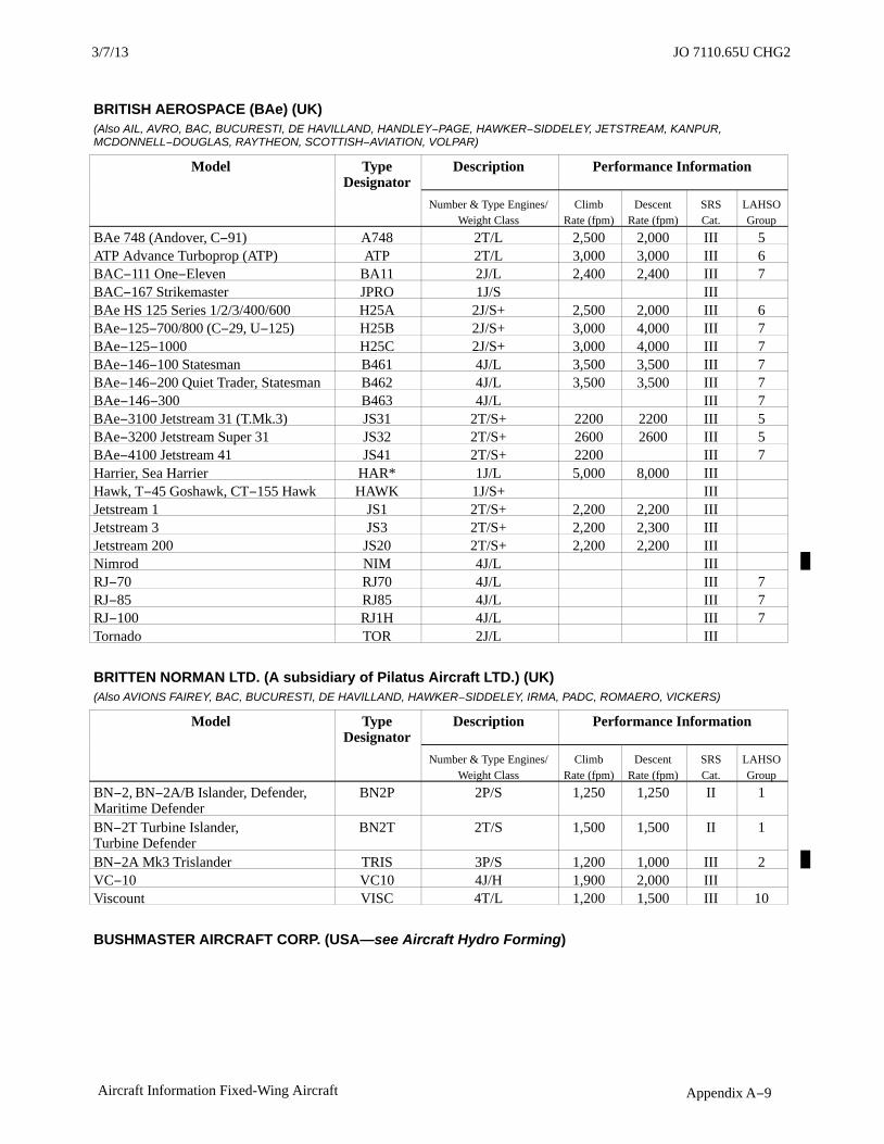
JO 7110.65U2/9/12
Appendix A−9Aircraft Information Fixed-Wing Aircraft
BRITISH AEROSPACE (BAe) (UK)(Also AIL, AVRO, BAC, BUCURESTI, DE HAVILLAND, HANDLEY−PAGE, HAWKER−SIDDELEY, JETSTREAM, KANPUR,MCDONNELL−DOUGLAS, RAYTHEON, SCOTTISH−AVIATION, VOLPAR)
Model TypeDesignator
Description Performance Information
Number & Type Engines/Weight Class
ClimbRate (fpm)
DescentRate (fpm)
SRSCat.
LAHSOGroup
BAe 748 (Andover, C−91) A748 2T/L 2,500 2,000 III 5ATP Advance Turboprop (ATP) ATP 2T/L 3,000 3,000 III 6BAC−111 One−Eleven BA11 2J/L 2,400 2,400 III 7BAC−167 Strikemaster JPRO 1J/S IIIBAe HS 125 Series 1/2/3/400/600 H25A 2J/S+ 2,500 2,000 III 6BAe−125−700/800 (C−29, U−125) H25B 2J/S+ 3,000 4,000 III 7BAe−125−1000 H25C 2J/S+ 3,000 4,000 III 7BAe−146−100 Statesman B461 4J/L 3,500 3,500 III 7BAe−146−200 Quiet Trader, Statesman B462 4J/L 3,500 3,500 III 7BAe−146−300 B463 4J/L III 7BAe−3100 Jetstream 31 (T.Mk.3) JS31 2T/S+ 2200 2200 III 5BAe−3200 Jetstream Super 31 JS32 2T/S+ 2600 2600 III 5BAe−4100 Jetstream 41 JS41 2T/S+ 2200 III 7Harrier, Sea Harrier HAR* 1J/L 5,000 8,000 IIIHawk, T−45 Goshawk, CT−155 Hawk HAWK 1J/S+ IIIJetstream 1 JS1 2T/S+ 2,200 2,200 IIIJetstream 3 JS3 2T/S+ 2,200 2,300 IIIJetstream 200 JS20 2T/S+ 2,200 2,200 IIINimrod NIM 4J/L IIIRJ−70 RJ70 4J/L III 7RJ−85 RJ85 4J/L III 7RJ−100 RJ1H 4J/L III 7Tornado TOR 2J/L III
BRITTEN NORMAN LTD. (A subsidiary of Pilatus Aircraft LTD.) (UK)(Also AVIONS FAIREY, BAC, BUCURESTI, DE HAVILLAND, HAWKER−SIDDELEY, IRMA, PADC, ROMAERO, VICKERS)
Model TypeDesignator
Description Performance Information
Number & Type Engines/Weight Class
ClimbRate (fpm)
DescentRate (fpm)
SRSCat.
LAHSOGroup
BN−2, BN−2A/B Islander, Defender,Maritime Defender
BN2P 2P/S 1,250 1,250 II 1
BN−2T Turbine Islander, Turbine Defender
BN2T 2T/S 1,500 1,500 II 1
BN−2A Mk3 Trislander TRIS 3P/S 1,200 1,000 III 2VC−10 VC10 4J/H 1,900 2,000 IIIViscount VISC 4T/L 1,200 1,500 III 10
BUSHMASTER AIRCRAFT CORP. (USA—see Aircraft Hydro Forming)
3/7/13 JO 7110.65U CHG2

JO 7110.65U 2/9/12
Appendix A−10 Aircraft Information Fixed-Wing Aircraft
CAMAIR AIRCRAFT CORP. (USA)(Also RILEY, TEMCO)
Model TypeDesignator
Description Performance Information
Number & Type Engines/Weight Class
ClimbRate (fpm)
DescentRate (fpm)
SRSCat.
LAHSOGroup
480 Twin Navion 480 TNAV 2P/S 1,800 2,000 II
CANADAIR BOMBARDIER LTD. (Canada)
Model TypeDesignator
Description Performance Information
Number & Type Engines/Weight Class
ClimbRate (fpm)
DescentRate (fpm)
SRSCat.
LAHSOGroup
CL−41 Tutor (CT−114) CL41 1J/S IIICL−44 Forty Four CL44 4T/L IIICL−44−O Guppy CL4G 4T/L IIICL−66, CV−580 (CC−109Cosmopolitan)
CVLT 2T/L 1,500 1,500 III 7
CL−600/Challenger 699/601/604(CC−144, CE−144)
CL60 2J/L 2,250 3,000 III 8
CL−600 Regional Jet CRJ−100, RJ−100 CRJ1 2J/L III 7CL−600, Regional Jet CRJ−200,RJ−200
CRJ2 2J/L III 7
CL−600 Regional Jet CRJ−700 CRJ7 2J/L III 7CL−600 Regional Jet CRJ−900 CRJ9 2J/L III 8T−33, CT−133 Silver Star (CL−30) T33 1J/L 2,000 2,000 III
CESSNA AIRCRAFT COMPANY (USA)(Also AVIONES−COLOMBIA, COLEMILL, DINFIA, ECTOR, FMA, FUJI, REIMS, RILEY, SUMMIT, WREN)
Model TypeDesignator
Description Performance Information
Number & Type Engines/Weight Class
ClimbRate (fpm)
DescentRate (fpm)
SRSCat.
LAHSOGroup
A−37 Dragonfly (318D/E), OA−37 A37* 2J/S 3,370 3,000 III120 C120 1P/S 640 640 I 1140 C140 1P/S 640 640 I 3150, A150, Commuter, Aerobat C150 1P/S 670 1,000 I 1152, A152, Aerobat C152 1P/S 750 1,000 I 1170 C170 1P/S 690 1,000 I 4172, P172, R172, Skyhawk, Hawk XP, Cutlass (T−41, Mescalero)
C172 1P/S 650 1,000 I 1
172RG, Cutlass RG C72R 1P/S 650 1,000 I 1175, Skylark C175 1P/S 850 1,000 I 2177, Cardinal C177 1P/S 850 1,000 I 2177, Cardinal RG C77R 1P/S 850 1,000 I 2180, Skywagon 180 (U−17C) C180 1P/S 1,130 1,130 I 2182, Skylane C182 1P/S 890 1,000 I 2R182, TR182 (Turbo) Skylane RG C82R 1P/S 890 1,000 I 2185, A185 Skywagon, Skywagon 185,AgCarryall (U−17A/B)
C185 1P/S 1,000 1,000 I 2
3/15/077110.65R CHG 2JO 7110.65U CHG 2 3/7/13

JO 7110.65U2/9/12
Appendix A−11Aircraft Information Fixed-Wing Aircraft
Model TypeDesignator
Description Performance Information
Number & Type Engines/Weight Class
ClimbRate (fpm)
DescentRate (fpm)
SRSCat.
LAHSOGroup
188, A188, T188 AgWagon, AgPickupAgTruck, AgHusky
C188 1P/S 1,000 1,000 I 1
190 C190 1P/S 1,090 1,090 I 2195 (LC−126) C195 1P/S 1,200 1,200 I205 C205 1P/S 965 1,000 I 3206, P206m T206m TP206, U206,TU206, (Turbo) Super Skywagon,(Turbo) Super Skyland, (Turbo)Skywagon 206, (Turbo) Stationair,Turbo Stationair 6
C206 1P/S 975 1,000 I 2
206 (turbine) C06T 1/T/S I207 (Turbo) Skywagon 207, (Turbo)Stationair 7/8
C207 1P/S 810 1,000 I 2
207 (turbine) C07T 1T/S I208 Caravan 1, (Super) Cargomaster, Grand Caravan (C−98,U27)
C208 1T/S 1,400 1,400 I 3
210, T210, (Turbo) Centurion C210 1P/S 900 1,000 I 2P210 Pressurized Centurion P210 1P/S 1,000 1,000 IP210 (turbine) C10T 1T/S IT303 Crusader C303 2P/S 3,500 3,000 II 2310, T310 (U−3, L−27) C310 2P/S 2,800 2,000 II 4320 (Executive) Skyknight C320 2P/S 2,900 2,000 II 5335 C335 2P/S 2,200 2,000 II 4336 Skymaster C336 2P/S 1,340 1,340 II337, M337, MC337, T337B/C/D/E/F/H(Turbo) Super Skymaster (O−2)
C337 2P/S 1,250 1,500 II 3
T337G, P337 Pressurized Skymaster P337 2P/S 1,250 1,500 II 3340 C340 2P/S 2,900 2,000 II 4350, Corvalis, Columbia 300/350,LC40/42
COL3 1P/S I
400, Corvalis TT, Columbia 400, LC 41 COL4 1P/S I401, 402, Utililiner, Businessliner C402 2P/S 2,500 2,000 II 3402 (turbine) C02T 2T/S II404 Titan C404 2P/S 2,600 2,000 II 5404 (turbine) C04T 2T/S IIF406 Caravan 2, Vigilant F406 2T/S 1,850 II 6411 C411 2P/S 2,800 2,000 II 4414, Chancellor 414 C414 2P/S 2,300 2,000 II 6414 (turbine) C14T 2T/S II421, Golden Eagle, ExecutiveCommuter
C421 2P/S II 6
421 (turbine) C21T 2T/S II425, Corsair, Conquest 1 C425 2T/S 3,500 2,500 II 5441 Conquest, Conquest 2 C441 2T/S 4,200 3,000 II 65000 Citation, Citation 1 C500 2J/S 3,100 3,500 III 6501 Citation 1SP C501 2J/S 4,300 3,000 III 6525 Citationjet Citation CJ1 C525 2J/S 3,000 III 7
3/7/13 JO 7110.65U CHG2

JO 7110.65U 2/9/12
Appendix A−12 Aircraft Information Fixed-Wing Aircraft
525A Citation CJ2 C25A 2J/S 3,870 III525B Citation CJ3 C25B 2J/S+ III526 Citationjet C526 2J/S 3,000 III
Model TypeDesignator
Description Performance Information
Number & Type Engines/Weight Class
ClimbRate (fpm)
DescentRate (fpm)
SRSCat.
LAHSOGroup
550, S550, 552 Citation 2/S2/Bravo(T−47, U−20)
C550 2J/S+ 5,300 3,000 III 7
551 Citation 2SP C551 2J/S 5,300 3,000 III 5560 Citation 5/5 Ultra/5Ultra Encore(UC−35, OT−47, TR−20)
C560 2J/S+ 6,000 3,500 III 8
650 Citation 3/6/7 C650 2J/S+ 3,900 4,000 III 8680 Citation Sovereign C680 2J/S+ III750 Citation 10 C750 2J/S+ 3,500 3,500 III 9AW CAW 1P/S IO−1, TO−1, OE, L−19, TL−19 Bird Dog(305,321)
O1 1P/S 1,150 1,150 I
T37 (318A/B/C) T37* 2J/S 3,000 3,000 IIIT−50 Bobcat (AT−8, AT−17, UC−78,Crane)
T50 2P/S II
DC−6 CDC6 1P/S IC−34/37/38/145/165, Airmaster CMAS 1P/S I
CHAMPION (USA−see Bellanca Aircraft)
CHRISTEN INDUSTRIES, INC. (USA)(Also AVIAT)
Model TypeDesignator
Description Performance Information
Number & Type Engines/Weight Class
ClimbRate (fpm)
DescentRate (fpm)
SRSCat.
LAHSOGroup
A−1 Huskey HUSK 1P/S 1,500 1,500 I
CIRRUS (USA)
Model TypeDesignator
Description Performance Information
Number & Type Engines/Weight Class
ClimbRate (fpm)
DescentRate (fpm)
SRSCat.
LAHSOGroup
SR−20, SR−20 SRV, SRV SR20 1P/S I 1SR−22 SR22 1P/S I 1VK−30 Cirrus VK3P 1P/S I
COLEMILL (USA) (See BEECH, PIPER, CESSNA)
CONSTRUCCIONES AERONAUTICAS (CASA) (Spain)(Also NURTANIO, NUSANTARA)
Model TypeDesignator
Description Performance Information
Number & Type Engines/Weight Class
ClimbRate (fpm)
DescentRate (fpm)
SRSCat.
LAHSOGroup
C−212 Aviocar (T−12, TE−12, TR−12,D−3, Tp89)
C212 2T/S+ 900 900 III 5
3/15/077110.65R CHG 2JO 7110.65U CHG 2 3/7/13
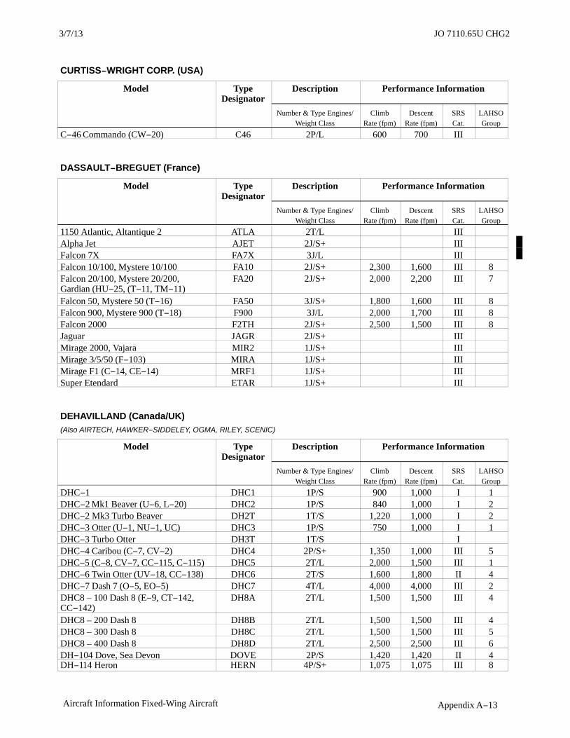
JO 7110.65U2/9/12
Appendix A−13Aircraft Information Fixed-Wing Aircraft
CURTISS−WRIGHT CORP. (USA)
Model TypeDesignator
Description Performance Information
Number & Type Engines/Weight Class
ClimbRate (fpm)
DescentRate (fpm)
SRSCat.
LAHSOGroup
C−46 Commando (CW−20) C46 2P/L 600 700 III
DASSAULT−BREGUET (France)
Model TypeDesignator
Description Performance Information
Number & Type Engines/Weight Class
ClimbRate (fpm)
DescentRate (fpm)
SRSCat.
LAHSOGroup
1150 Atlantic, Altantique 2 ATLA 2T/L IIIAlpha Jet AJET 2J/S+ IIIFalcon 7X FA7X 3J/L IIIFalcon 10/100, Mystere 10/100 FA10 2J/S+ 2,300 1,600 III 8Falcon 20/100, Mystere 20/200,Gardian (HU−25, (T−11, TM−11)
FA20 2J/S+ 2,000 2,200 III 7
Falcon 50, Mystere 50 (T−16) FA50 3J/S+ 1,800 1,600 III 8Falcon 900, Mystere 900 (T−18) F900 3J/L 2,000 1,700 III 8Falcon 2000 F2TH 2J/S+ 2,500 1,500 III 8Jaguar JAGR 2J/S+ IIIMirage 2000, Vajara MIR2 1J/S+ IIIMirage 3/5/50 (F−103) MIRA 1J/S+ IIIMirage F1 (C−14, CE−14) MRF1 1J/S+ IIISuper Etendard ETAR 1J/S+ III
DEHAVILLAND (Canada/UK)(Also AIRTECH, HAWKER−SIDDELEY, OGMA, RILEY, SCENIC)
Model TypeDesignator
Description Performance Information
Number & Type Engines/Weight Class
ClimbRate (fpm)
DescentRate (fpm)
SRSCat.
LAHSOGroup
DHC−1 DHC1 1P/S 900 1,000 I 1DHC−2 Mk1 Beaver (U−6, L−20) DHC2 1P/S 840 1,000 I 2DHC−2 Mk3 Turbo Beaver DH2T 1T/S 1,220 1,000 I 2DHC−3 Otter (U−1, NU−1, UC) DHC3 1P/S 750 1,000 I 1DHC−3 Turbo Otter DH3T 1T/S IDHC−4 Caribou (C−7, CV−2) DHC4 2P/S+ 1,350 1,000 III 5DHC−5 (C−8, CV−7, CC−115, C−115) DHC5 2T/L 2,000 1,500 III 1DHC−6 Twin Otter (UV−18, CC−138) DHC6 2T/S 1,600 1,800 II 4DHC−7 Dash 7 (O−5, EO−5) DHC7 4T/L 4,000 4,000 III 2DHC8 – 100 Dash 8 (E−9, CT−142,CC−142)
DH8A 2T/L 1,500 1,500 III 4
DHC8 – 200 Dash 8 DH8B 2T/L 1,500 1,500 III 4DHC8 – 300 Dash 8 DH8C 2T/L 1,500 1,500 III 5DHC8 – 400 Dash 8 DH8D 2T/L 2,500 2,500 III 6DH−104 Dove, Sea Devon DOVE 2P/S 1,420 1,420 II 4DH−114 Heron HERN 4P/S+ 1,075 1,075 III 8
3/7/13 JO 7110.65U CHG2

JO 7110.65U 2/9/12
Appendix A−14 Aircraft Information Fixed-Wing Aircraft
DIAMOND (Canada)(Also HOAC)
Model TypeDesignator
Description Performance Information
Number & Type Engines/Weight Class
ClimbRate (fpm)
DescentRate (fpm)
SRSCat.
LAHSOGroup
DA−20/22, DV−20 Katana, Speed Katana
DV20 1P/S 525 500 I 2
DA−42 TwinStar DA42 2P/S 1,100 500 II 2
DORNIER GmbH (FRG)(Also CASA, HINDUSTAN. Also see FAIRCHILD−DORNIER)
Model TypeDesignator
Description Performance Information
Number & Type Engines/Weight Class
ClimbRate (fpm)
DescentRate (fpm)
SRSCat.
LAHSOGroup
228 D228 2T/S+ 2,000 2,000 III 2328 D328 2T/S+ 2,000 2,000 III 727 DO27 1P/S 700 800 I 1Do 28 A/B (Agur) DO28 2P/S 1,500 1,500 IIDo 28D/D−1/D−2, 128−2 Skyservant D28D 2P/S 1,000 − II 1Do−28D−6, 128−6 Turbo Skyservant D28T 2T/S 1,500 − II 1
ECLIPSE AVIATION (USA)
Model TypeDesignator
Description Performance Information
Number & Type Engines/Weight Class
ClimbRate (fpm)
DescentRate (fpm)
SRSCat.
LAHSOGroup
Eclipse 500 EA50 2J/S 1,725 3,000 III 4
EMBRAER (Brazil)
Model TypeDesignator
Description Performance Information
Number & Type Engines/Weight Class
ClimbRate (fpm)
DescentRate (fpm)
SRSCat.
LAHSOGroup
CBA−123 Vector VECT 2T/S+ IIIEMB−110/111 Bandeirante (C−95,EC−95, P−95, R−95, SC−95)
E110 2T/S+ 1,500 1,500 III 7
EMB−120 Brasilia (VC−97) E120 2T/S+ 2,300 2,300 III 7EMB−121 Xingu (VU−9, EC−9) E121 2T/S+ IIIEMB−135, ERJ−135/140 E135 2J/L 2,410 2,030 III 7EMB−145, ERJ−145 (R−99) E145 2J/L 2,350 2,190 III 7EMB−145XR E45X 2J/L III 7EMB−170/175 E170 2J/L III 7EMB−190/195 E190 2J/L III 7EMB−500, Phenom 100 E50P 2J/S IIIEMB−505, Phenom 300 E55P 2J/S+ III
3/15/077110.65R CHG 2JO 7110.65U CHG 2 3/7/13

JO 7110.65U2/9/12
Appendix A−15Aircraft Information Fixed-Wing Aircraft
EXTRA (FRG)
Model Type Designator Description Performance InformationNumber & Type Engines/
Weight ClassClimb
Rate (fpm)Descent
Rate (fpm)SRSCat.
LAHSOGroup
200 E200 1P/S 1,000 1,000 I230 E230 1P/S 1,500 1,500 I300, 350 E300 1P/S 2,500 1,500 I400 E400 1P/S 1,500 1,500 I500 E500 1T/S 1,800 1,800 I
FAIRCHILD DORNIER (USA/FRG)(Also CONAIR, FAIRCHILD−HILLER, FLEET, FOKKER, KAISER, PILATUS, SWEARINGEN)
Model Type Designator Description Performance InformationNumber & Type Engines/
Weight ClassClimb
Rate (fpm)Descent
Rate (fpm)SRSCat.
LAHSOGroup
228 D228 2T/S+ 2,000 2,000 III328 D328 2T/S+ 2,000 2,000 III 7328JET, Envoy 3 J328 2J/S+ III 6728JET, Envoy 7 J728 2J/L III
FAIRCHILD INDUSTRIES (USA)(Also CONAIR, FAIRCHILD−HILLER, FLEET, FOKKER, KAISER, PILATUS, SWEARINGEN)
Model Type Designator Description Performance InformationNumber & Type Engines/
Weight ClassClimb
Rate (fpm)Descent
Rate (fpm)SRSCat.
LAHSOGroup
A−10, OA−10 Thunderbolt 2 A10* 2J/L 6,000 5,000 IIIC−119, R4Q Flying Box Car (F−78) C119 2P/L 750 750 III 5C−123 Provider C123 2P/L 890 1,000 IIIF−27, FH−227 F27 2T/L 3,000 3,000 III 5M−62 (PT−19/23/26, T−19 Cornell) FA62 1P/S 650 650 IPilatus/Peacemaker/Porter PC6P 1P/S 580 600 IPC−6 Heli−Porter PC6T 1T/S 580 600 IMerlin 2 SW2 2T/S 2,350 2,500 II 6SA−226TB, SA−227TT Merlin 3, Fairchild 300
SW3 2T/S+ 2,350 2,500 III 5
SA−226AC, SA−227AC/AT Metro,Merlin 4, Expediter
SW4 2T/S+ 2,400 2,500 III 5
FOKKER BV (Netherlands)(Also FAIRCHILD, FAIRCHILD−HILLER)
Model Type Designator Description Performance InformationNumber & Type Engines/
Weight ClassClimb
Rate (fpm)Descent
Rate (fpm)SRSCat.
LAHSOGroup
F−27 Friendship, Troopship, Maritime (C−31, D−2)
F27 2T/L 3,000 3,000 III
F−28, Fellowship F28 2J/L 4,650 2,000 III 750, Maritime Enforcer F50 2T/L 3,500 3,500 III 360 F60 2T/L 3,500 3,500 III70 F70 2J/L 4,500 3,000 III100 F100 2J/L 3,500 3,500 III 7
3/7/13 JO 7110.65U CHG2

JO 7110.65U 2/9/12
Appendix A−16 Aircraft Information Fixed-Wing Aircraft
GAF (Australia)
Model Type Designator Description Performance InformationNumber & Type Engines/
Weight ClassClimb
Rate (fpm)Descent
Rate (fpm)SRSCat.
LAHSOGroup
N2/22/24 Nomad, Floatmaster,Missionmaster, Searchmaster
NOMA 2T/S 1,300 1,100 II 2
GATES LEARJET CORP. (USA)(Also LEAR JET, LEARJET, SHIN MEIWA)
Model Type Designator Description Performance InformationNumber & Type Engines/
Weight ClassClimb
Rate (fpm)Descent
Rate (fpm)SRSCat.
LAHSOGroup
23 LJ23 2J/S 4,500 4,000 III 824 LJ24 2J/S+ 4,500 4,000 III 725 LJ25 2J/S+ 4,500 4,000 III 928, 29 LJ28 2J/S+ 4,500 4,000 III 731 LJ31 2J/S+ 4,500 4,000 III 735, 36 (C−21, RC−35, RC−36, U−36) LJ35 2J/S+ 4,500 4,000 III 940 LJ40 2J/S+ III45 LJ45 2J/S+ III55 LJ55 2J/S+ 5,000 4,000 III 860 LJ60 2J/S+ 5,000 4,000 III 10
GENERAL DYNAMICS CORP. (USA)(Also BOEING CANADA, CANADAIR, CANADIAN VICKERS, CONSOLIDATED, CONVAIR, FOKKER, GRUMMAN, KELOWNA, LOCKHEED, LOCKHEED MARTIN, MITSUBISHI, SABCA, SAMSUNG, TUSAS)
Model Type Designator Description Performance InformationNumber & Type Engines/
Weight ClassClimb
Rate (fpm)Descent
Rate (fpm)SRSCat.
LAHSOGroup
Canso/Catalina*** CAT 2P/S+ 600 600 III 7Convair 240/340/440, Liner, HC−131 CVLP 2P/L 1,000 800 III 7Convair 540/580/600/640 CVLT 2T/L 1,500 1,500 III 7F−111, EF−111, (RF−111 Aardvark,Raven
F111* 2J/L 5,000 5,000 III
F−16 A/B/C/D/N, NF−16, TF−16Fighting Falcon, Netz, Barak, Brakeet
F16* 1J/L 8,000 5,000 III
F−16XL Fighting Falcon F16X* 1J/L IIIValiant VALI 1P/S 600 750 I
GREAT LAKES (USA)
Model Type Designator Description Performance InformationNumber & Type Engines/
Weight ClassClimb
Rate (fpm)Descent
Rate (fpm)SRSCat.
LAHSOGroup
2T−1 Sport Trainer, Sport G2T1 1P/S 1,000 800 I

JO 7110.65U2/9/12
Appendix A−17Aircraft Information Fixed-Wing Aircraft
GROB (FRG)
Model Type Designator Description Performance InformationNumber & Type Engines/
Weight ClassClimb
Rate (fpm)Descent
Rate (fpm)SRSCat.
LAHSOGroup
G109 Ranger (Vigilant) G109 1P/S 600 600 I 2G115 A/B/C/D/E, Bavarian (Heron),Tutoa
G115 1P/S 1,200 1,100 I
G−120 G120 1P/S 1,280 I
GRUMMAN AEROSPACE CORP. (USA)(Also AERO MOD, AMERICAN GENERAL, GRUMMAN AMERICAN, GULFSTREAM AMERICANMID−CONTINENT, NORTHROP GRUMMAN, SERV−AERO)
Model Type Designator Description Performance InformationNumber & Type Engines/
Weight ClassClimb
Rate (fpm)Descent
Rate (fpm)SRSCat.
LAHSOGroup
A−6, EA−6, KA−6 Intruder, Prowler (G−128)
A6* 2J/L 7,500 5,000 III
AA1 Trainer,Tr2, T−Cat, Lynx AA1 1P/S 850 1,250 I 1AA−5, Traveller, Cheetah Tiger AA5 1P/S 660 1,000 I 1C−1, TF Trader (G−96) G96 2P/S+ IIIC−2 Greyhound C2 2T/L 1,000 2,200 IIIE−2, TE−2, Hawkeye, Daya E2 2T/L 2,690 3,000 IIIF−3F (G−11/32), Replica F3F 1P/S IF−6F Hellcat (G−50) HCAT 1P/S+ IIIF−7F Tigercat (G−51) TCAT 2P/S+ IIIF−9F Panther (G−79) F9F 1JS+ IIIF−14 Tomcat F14* 2J/L 6,000 4,000 IIIG−164 Ag−Cat, Super Ag−Cat G164 1P/S 1,500 1,500 I 1G164 Turbo Ag−Cat G64T 1T/S 1,500 1,500 I 1G−21 A/38/39 Goose (JRF)*** G21 2P/S 1,000 1,000 IIG−44 Widgeon (J4F)*** G44 2P/S 1,000 1,500 II 5G−73 Mallard*** G73 2P/S+ 1,600 1,600 III 6G−73T Turbo Mallard*** G73T 2T/S+ IIIG−1159, G−1159B Gulfstream2/2B/2SP (C−20J, VC−111)
GLF2 2J/L 5,000 4,000 III 8
GA−7 Cougar GA7 2P/S 1,600 1,500 II 1HU−16, SA−16, UF Albatross(G−64/111)***
U16 2P/S+ 1,500 1,500 III 4
OV−1, RV−1, AO−1 Mohawk (G−134) V1 2T/S+ 2,100 1,300 IIIS−2, S2F, P−16 Tracker (G−89) S2P 2P/S+ IIIS−2 Turbo Tracker S2T 2T/S+ IIIX−29 (712) X29 1J/S+ III
GULFSTREAM AEROSPACE CORP. (USA)(Also GRUMMAN, GRUMMAN AMERICAN, GULFSTREAM, GULFSTREAM AMERICAN, IAI)
Model Type Designator Description Performance InformationNumber & Type Engines/
Weight ClassClimb
Rate (fpm)Descent
Rate (fpm)SRSCat.
LAHSOGroup
690 Jetprop Commander 840/900 AC90 2T/S 2,500 2,500 II695 Jetprop Commander 980/1000 AC95 2T/S 2,500 2,500 II 6AA−1 T−Cat, Lynx AA1 1P/S 850 1,250 I
3/7/13 JO 7110.65U CHG2

JO 7110.65U 2/9/12
Appendix A−18 Aircraft Information Fixed-Wing Aircraft
Model Type Designator Description Performance InformationNumber & Type Engines/
Weight ClassClimb
Rate (fpm)Descent
Rate (fpm)SRSCat.
LAHSOGroup
AA−5 Traveler, Cheetah, Tiger AA5 1P/S 660 1,000 IGA−7 Cougar GA7 2P/S 1,600 1,500 IIGAC 159−C, Gulfstream 1 G159 2T/S+ 2,000 2,000 III 7G−1159, G−1159B/TT, Gulfstream2/2B/2SP/2TT
GLF2 2J/L 5,000 4,000 III 8
G−1159A Gulfstream 3/SRA−1,SMA−3 (C20A/B/C/D/E)
GLF3 2J/L 5,000 4,000 III 8
G−1159C Gulfstream 300/4/4SP/400/SRA−4 (C−20F/G/H, S102,Tp102, U−4)
GLF4 2J/L 5,000 4,000 III 8
G−1159D Gulfstream 5/500/550(C−37)
GLF5 2J/L 5,000 4,000 III 7
HAMILTON AVIATION (USA)(Also VOLPAR)
Model Type Designator Description Performance InformationNumber & Type Engines/
Weight ClassClimb
Rate (fpm)Descent
Rate (fpm)SRSCat.
LAHSOGroup
Westwind 2/3 B18T 2T/S 2,000 2,000 II 1Little Liner BE18 2P/S 1,400 1,000 II 4T−28 Nomair T28 1P/S 2,500 2,500 III
HANDLEY PAGE (UK)(Also BRITISH AEROSPACE, JETSTREAM, SCOTTISH AVIATION, VOLPAR)
Model Type Designator Description Performance InformationNumber & Type Engines/
Weight ClassClimb
Rate (fpm)Descent
Rate (fpm)SRSCat.
LAHSOGroup
HP−137 Jetstream 1 JS1 2T/S+ 2,200 2,200 IIIHP−137 Jetstream 200 (T.Mk1/2) JS20 2T/S+ 2,200 2,200 III
HELIO AIRCRAFT COMPANY (USA)
Model Type Designator Description Performance InformationNumber & Type Engines/
Weight ClassClimb
Rate (fpm)Descent
Rate (fpm)SRSCat.
LAHSOGroup
H−391/392/395/250/295/700/800,HT−295 Courier, Strato−Courier, Super Courier (U−10)
COUR 1P/S 850 1,000 I 1
HST−550 Stallion (AU−24) STLN 1T/S 2,200 2,200 I 1H−500 Twin Courier (U−5) TCOU 2P/S 1,250 1,500 II 1
HFB (FRG)(Also MBB)
Model Type Designator Description Performance InformationNumber & Type Engines/
Weight ClassClimb
Rate (fpm)Descent
Rate (fpm)SRSCat.
LAHSOGroup
HFB−320 Hansa HF20 2J/S+ 4,500 4,500 III 7
3/15/077110.65R CHG 2JO 7110.65U CHG 2 3/7/13

JO 7110.65U2/9/12
Appendix A−19Aircraft Information Fixed-Wing Aircraft
HOWARD (USA)
Model Type Designator Description Performance InformationNumber & Type Engines/
Weight ClassClimb
Rate (fpm)Descent
Rate (fpm)SRSCat.
LAHSOGroup
250, 350 L18 2P/L 1,800 2,000 III 8DGA−15 (GH Nightingale, NH) DG15 1P/S 1,000 1,000 I
IAI (Israel)(Also ISRAEL AIRCRAFT INDUSTRIES, ASTRA, GULFSTREAM)
Model Type Designator Description Performance InformationNumber & Type Engines/
Weight ClassClimb
Rate (fpm)Descent
Rate (fpm)SRSCat.
LAHSOGroup
101 Avara, 102, 201, 202 ARVA 2T/S+ 1,300 1,000 III 51123 Westwind WW23 2J/S+ 4,000 3,500 III 71124 Westwind WW24 2J/S+ 4,000 3,500 III 71125 Gulfstream 100, (C−38) ASTR 2J/S+ 4,000 3,500 III 71126 Gulfstream 200 GALX 2J/S+ IIIGulfstream 150 G150 2J/S+ III
ILYUSHIN (Russia)
Model Type Designator Description Performance InformationNumber & Type Engines/
Weight ClassClimb
Rate (fpm)Descent
Rate (fpm)SRSCat.
LAHSOGroup
A−50, Be−976 A50 4J/H IIIIl−14 IL14 2P/S+ IIIIl−18/20/22/24, Bizon, Zebra IL18 4T/L IIIIl−28 IL28 2J/L IIIIl−38 IL38 4T/L IIIIL−62 IL62 4J/H 3,500 2,500 IIIIL−76/78/82, Gajaraj IL76 4J/H 3,000 2,500 IIIIl−86/87 IL86 4J/H IIIIl−96 IL96 4J/H IIIIl−103 I103 1P/S IIl−114 I114 2T/L III
JETSTREAM (UK − see British Aerospace)
LAKE AIRCRAFT (USA)
Model Type Designator Description Performance InformationNumber & Type Engines/
Weight ClassClimb
Rate (fpm)Descent
Rate (fpm)SRSCat.
LAHSOGroup
LA−250/270 (Turbo) Renegade,Seawolf, SeaFury***
LA25 1P/S 700 700 I 2
LA−4/200, Buccaneer*** LA4 1P/S 1,100 1,000 I 2
3/7/13 JO 7110.65U CHG2

JO 7110.65U 2/9/12
Appendix A−20 Aircraft Information Fixed-Wing Aircraft
LOCKHEED CORP. (USA)(Also AERITALIA, CANADAIR, FIAT, FOKKER, HOWARD, LEAR, LOCKHEED−BOEING, LOCKHEED−MARTIN, MBB,MESSERSCHMITT, MITSUBISHI, PACAERO, ROCKWELL, SABCA)
Model Type Designator Description Performance InformationNumber & Type Engines/
Weight ClassClimb
Rate (fpm)Descent
Rate (fpm)SRSCat.
LAHSOGroup
B−34, PV Venture, Harpoon(L−15/137/237)
L37 2P/S+ III
C−5 Galaxy (L−500) C5 4J/H 2,500 2,000 IIIC−130A/B/E/F/H, CC−130, DC−130,EC−130/E/G/H/Q, HC−130, JC−130,KC−130B/F/H/R/T, LC−130, MC−130,NC−130, RC−130, TC−130, VC−130,WC−130E/H, T−10, TK−10, TL−10,Tp84 Hercules, Spectre, Aya, Karnaf,Sapeer (L−100/182/282/382)
C130 4T/L 1,500 1,500 III
C−141 Starlifter (L−300) C141 4J/H 3,500 3,000 IIIL−049/749/1049 Constellation, Super Constellation, Starliner (C−121,RC−121, EC−121, VC−121, WV, R7V,Warning Star)
CONI 4P/L 1,700 1,700 III 9
F−22 Raptor (L−645) F22* 2J/L IIIF−104, RF−104, TF−104 Starfighter(L583/683)
F104* 1J/L 5,000 4,000 III
F−117 Nighthawk F117* 2J/L IIIL−1011 Tri−Star (all series) L101 3J/H 3,500 3,000 III 9L−18 Lodestar (C−56/57/59/60, R50,XR50)
L18 2P/S 1,800 2,000 III 8
L−188 Electra L188 4T/L 1,850 2,000 III 7L−1329 Jetstar 6/8 L29A 4J/L 4,000 3,500 III 8L−1329−5 Jetstar 2/731 L29B 4J/L 4,000 3,000 III 9P−2D to H, SP−2, P2V Neptune(L−426/726/826)
P2 2P/L III
P−3, AP−3, EP−3, NP−3, RP−3, TP−3,UP−3, VP−3, WP−3, CP−140 Orion,Aurora, Arcturus (L−85/285/685/785)
P3 4T/L 1,850 2,000 III
P−38, F−5 Lightning (L−222/322/422) P38 2P/S+ IIIS−3, ES−3, US−3 Viking (L−394) S3 2J/L 2,000 2,000 IIISR−71 Blackbird SR71 2J/L IIIT−33, AT−33, NT−33, RT−33 ShootingStar, T−Bird (L−580)
T33* 2J/L 2,000 2,000 III
U−2, ER−2 U2* 1J/S+ 6,000 6,000 III
MARTIN COMPANY (USA)
Model Type Designator Description Performance InformationNumber & Type Engines/
Weight ClassClimb
Rate (fpm)Descent
Rate (fpm)SRSCat.
LAHSOGroup
404 M404 2P/L 1,600 1,500 III 3B−26 Marauder (179) B26M 2P/S+ IIIWB−57 (272) WB57 2J/L III
3/15/077110.65R CHG 2JO 7110.65U CHG 2 3/7/13

JO 7110.65U2/9/12
Appendix A−21Aircraft Information Fixed-Wing Aircraft
MAULE AIRCRAFT CORP. (USA)(Also SAASA)
Model Type Designator Description Performance InformationNumber & Type Engines/
Weight ClassClimb
Rate (fpm)Descent
Rate (fpm)SRSCat.
LAHSOGroup
M−4 Bee Dee, Jetasen, Rocket, Astro Rocket, Strata Rocket
M4 1P/S 1,000 1,000 I 1
M−5, Strata Rocket, Lunar Rocket, Patroller
M5 1P/S 1,000 1,000 I 1
M−6 Super−Rocket M6 1P/S 1,500 1,000 I 1M−7−235/260, MT−7−235/260,MX−7−160/180/235, MXT−7−160/180Super Rocket, Star Rocket, Comet,Star Craft, Orion, Sportplane
M7 1P/S 825 I 1
M−7−420, MT−7−240, MX−7−420,MXT−7−420 Star Craft
M7T 1T/S 4,500 I 1
M−8 M8 1P/S I
MCDONNELL−DOUGLAS CORP. (USA)(Also ASTA, BOEING, DOUGLAS, GAF, LISUNOV, MITSUBISHI, ON MARK, SHANGHAI, VALMET)
Model Type Designator Description Performance InformationNumber & Type Engines/
Weight ClassClimb
Rate (fpm)Descent
Rate (fpm)SRSCat.
LAHSOGroup
Skywarrior A3* 2J/L 5,000 6,000 IIIA−4, OA−4, TA−4 Skyhawk A4* 1J/S+ 5,000 5,000 IIIInvader B26 2P/L 1,000 1,000 IIIYC−15 C15 4J/L IIIC−17 Globemaster 3 C17 4J/H IIIDC−10 (KC−10 Extender, KDC−10,MD−10)
DC10 3J/H 2,400 2,000 III 9
Skytrain (C−47, C−53, C−117 A/B/C,R4D 1 to 7)
DC3 2P/S+ 1,200 1,200 III
Super DC−3 (C−117D, R4D 8) DC3S 2P/S+ 1,330 1,330 III 8Skymaster DC4 4P/L 2,300 2,300 III 7DC−6/B Liftmaster DC6 4P/L 1,000 1,000 III 7DC−7/B/C Seven Seas DC7 4P/L 1,250 1,250 III 8DC−8−50, Jet Trader DC85 4J/H 4,000 4,000 III 9DC−8−60 DC86 4J/H 4,000 4,000 IIIDC−8−70 DC87 4J/H 5,000 4,000 III 9DC−9−10 DC91 2J/L 3,000 3,000 III 8DC−9−20 DC92 2J/L 3,000 3,000 III 8DC−9−30 (C−9, VC−9, Nightingale,Skytrain 2)
DC93 2J/L 3,000 3,000 III 8
DC−9−40 DC94 2J/L 3,000 3,000 III 8DC−9−50 DC95 2J/L 3,000 3,000 III 8F−15 Eagle, Baz, Akef, Ra’am F15* 2J/L 8,000 5,000 IIIFA−18, CF−18, CF−188, EF−18, C−15,CE−15, AF−18, ATF−18 Hornet, Super Hornet
F18* 2J/L 8,000 6,000 III
F−4, RF−4, QF−4 Phantom 2/2000,Kurnass
F4* 2J/L 8,000 6,000 III
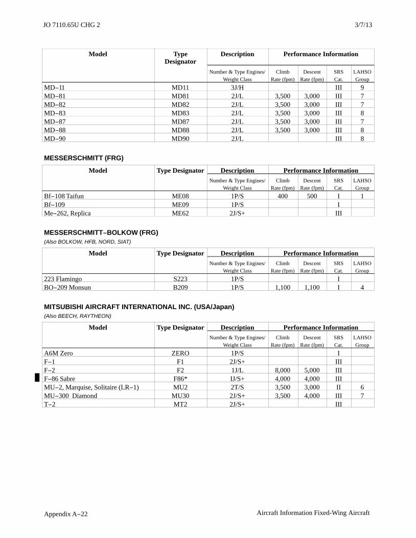
JO 7110.65U 2/9/12
Appendix A−22 Aircraft Information Fixed-Wing Aircraft
Model TypeDesignator
Description Performance Information
Number & Type Engines/Weight Class
ClimbRate (fpm)
DescentRate (fpm)
SRSCat.
LAHSOGroup
MD−11 MD11 3J/H III 9MD−81 MD81 2J/L 3,500 3,000 III 7MD−82 MD82 2J/L 3,500 3,000 III 7MD−83 MD83 2J/L 3,500 3,000 III 8MD−87 MD87 2J/L 3,500 3,000 III 7MD−88 MD88 2J/L 3,500 3,000 III 8MD−90 MD90 2J/L III 8
MESSERSCHMITT (FRG)
Model Type Designator Description Performance InformationNumber & Type Engines/
Weight ClassClimb
Rate (fpm)Descent
Rate (fpm)SRSCat.
LAHSOGroup
Bf−108 Taifun ME08 1P/S 400 500 I 1Bf−109 ME09 1P/S IMe−262, Replica ME62 2J/S+ III
MESSERSCHMITT−BOLKOW (FRG)(Also BOLKOW, HFB, NORD, SIAT)
Model Type Designator Description Performance InformationNumber & Type Engines/
Weight ClassClimb
Rate (fpm)Descent
Rate (fpm)SRSCat.
LAHSOGroup
223 Flamingo S223 1P/S IBO−209 Monsun B209 1P/S 1,100 1,100 I 4
MITSUBISHI AIRCRAFT INTERNATIONAL INC. (USA/Japan)(Also BEECH, RAYTHEON)
Model Type Designator Description Performance InformationNumber & Type Engines/
Weight ClassClimb
Rate (fpm)Descent
Rate (fpm)SRSCat.
LAHSOGroup
A6M Zero ZERO 1P/S IF−1 F1 2J/S+ IIIF−2 F2 1J/L 8,000 5,000 IIIF−86 Sabre F86* IJ/S+ 4,000 4,000 IIIMU−2, Marquise, Solitaire (LR−1) MU2 2T/S 3,500 3,000 II 6MU−300 Diamond MU30 2J/S+ 3,500 4,000 III 7T−2 MT2 2J/S+ III
3/15/077110.65R CHG 2JO 7110.65U CHG 2 3/7/13

JO 7110.65U2/9/12
Appendix A−23Aircraft Information Fixed-Wing Aircraft
MOONEY AIRCRAFT CORP. (USA)(Also AEROSTAR, ALON)
Model Type Designator Description Performance InformationNumber & Type Engines/
Weight ClassClimb
Rate (fpm)Descent
Rate (fpm)SRSCat.
LAHSOGroup
A−2 Aircoupe ERCO 1P/S 630 630 I 2M−10 Cadet M10 1P/S 800 800 I 1M−18 Mite, Wee Scotsman MITE 1P/S 750 750 I 1M−20, M−20/A/B/C/D/E/F/G/J/L/R/S, Mark 21, Allegro, Eagle, Ranger, Master, Super 21, Chaparral, Executive, Statesman, Ovation, 201,202, 205, 220, ATS, MSE, PFM (nonturbocharged engine)
M20P 1P/S 1,000 1,000 I 4
M−20K/M, Encore, Bravo, 231, 252,TLS, TSE (turbocharged engine)
M20T 1P/S 1,500 1,200 I 6
M−22, Mustang M22 1P/S 1,300 1,300 I 3
MUDRY (France)
Model Type Designator Description Performance InformationNumber & Type Engines/
Weight ClassClimb
Rate (fpm)Descent
Rate (fpm)SRSCat.
LAHSOGroup
CAP−10 CP10 1P/S 1,500 2,000 I 4CAP−20 CP20 1P/S 1,500 2,000 I 4CAP−21 CP21 1P/S ICAP−230/231/232 CP23 1P/S ID−140 Mousquetaire D140 1P/S I
NAMC (Japan)(Also MITSUBISHI)
Model Type Designator Description Performance InformationNumber & Type Engines/
Weight ClassClimb
Rate (fpm)Descent
Rate (fpm)SRSCat.
LAHSOGroup
YS−11 YS11 2T/L 1,500 1,500 III 6
NAVION (USA)(Also CAMAIR, RILEY, TEMCO)
Model Type Designator Description Performance InformationNumber & Type Engines/
Weight ClassClimb
Rate (fpm)Descent
Rate (fpm)SRSCat.
LAHSOGroup
Rangemaster RANG 1P/S 1,250 1,500 I 1
NOORDYUN AVIATION LTD. (Canada)(Also CCF)
Model Type Designator Description Performance InformationNumber & Type Engines/
Weight ClassClimb
Rate (fpm)Descent
Rate (fpm)SRSCat.
LAHSOGroup
Norseman Mk 4/5/6 NORS 1P/S 700 1,000 I 2

JO 7110.65U 2/9/12
Appendix A−24 Aircraft Information Fixed-Wing Aircraft
NORD (France)(Also AEROSPATIALE, HOLSTE, NORDFLUG, TRANSALL)
Model Type Designator Description Performance InformationNumber & Type Engines/
Weight ClassClimb
Rate (fpm)Descent
Rate (fpm)SRSCat.
LAHSOGroup
Transall C−160 C160 2T/L 2,000 2,000 III260 Super Broussard N260 2T/S+ 2,500 2,000 III262, Frégate, Mohawk 298 N262 2T/S+ 2,500 2,000 III1000, 1001, 1002 Pingouin ME08 1P/S 400 500 I 11101, 1102, Noralpha, Ramier N110 1P/S I1200 to 1204 Norecrin N120 1P/S I2501 to 2508 Noratlas NORA 2P/L 1,500 1,500 III3202 N320 1P/S I3400 N340 1P/S ISV−4 SV4 1P/S I
NORTHERN AVIATION (USA−see Bellanca)
NORTHROP CORP. (USA)(Also CANADAIR, CASA, AIDC, F+W EMMEN, KOREAN AIR, NORTHROP GRUMMAN)
Model Type Designator Description Performance InformationNumber & Type Engines/
Weight ClassClimb
Rate (fpm)Descent
Rate (fpm)SRSCat.
LAHSOGroup
B−2 Spirit B2 4J/H IIIC−125 Raider C125 3P/L IIIE−2 Hawkeye E2 2T/L 2,690 3,000 IIIF−5, RF−5 Freedom Fighter, Tiger 2,Tigereye (N−156C/F)
F5* 2J/S+ 8,000 5,000 III
P−61 Black Widow P61 2P/S+ IIIT−38, AT−38 Talon (N−156T) T38* 2J/S+ 8,000 5,000 III
PARTENAVIA (Italy)
Model Type Designator Description Performance InformationNumber & Type Engines/
Weight ClassClimb
Rate (fpm)Descent
Rate (fpm)SRSCat.
LAHSOGroup
AP−68TP−300 Spartacus P68T 2T/S 1,500 1,500 II 3AP−68TP−600 Viator VTOR 2T/S 1,500 1,500 II 8P−57 Fachiro 2 P57 1P/S IP−64/66 Oscar, Charlie OSCR 1P/S 800 1,000 I 2P68,Victor, Observer P68 2P/S 1,200 1,000 II 3
3/15/077110.65R CHG 2JO 7110.65U CHG 2 3/7/13

JO 7110.65U2/9/12
Appendix A−25Aircraft Information Fixed-Wing Aircraft
PIAGGIO (Industrie Aeronautiche E Meccaniche Rinaldo Piaggio SpA) (Italy)(Also PIAGGIO−DOUGLAS, TRECKER)
Model Type Designator Description Performance InformationNumber & Type Engines/
Weight ClassClimb
Rate (fpm)Descent
Rate (fpm)SRSCat.
LAHSOGroup
P−136*** P136 2P/S 1,250 1,500 II 4P−148 P148 1P/S IP−149 P149 1P/S IP−166, P−166A/B/C/DL2/M/S,Portofino, Albatross
P66P 2P/S 1,350 1,500 II 3
P−166DL3/DP1 P66T 2T/S IIP−180 Avanti P180 2T/S II 1
PILATUS FLUGZEUGWERKE AG (Switzerland)(Also FAIRCHILD, FAIRCHILD−HILLER)
Model Type Designator Description Performance InformationNumber & Type Engines/
Weight ClassClimb
Rate (fpm)Descent
Rate (fpm)SRSCat.
LAHSOGroup
P−2 PP2 1P/S IP−3 PP3 1P/S IPC−6 Porter PC6P 1P/S 600 600 IPC−6A/B/C Turbo Porter (UV−20Chiricahua)
PC6T 1T/S 1,250 1,500 I
PC−7 Turbo Trainer (AT−92, Astra) PC7 1T/S 2,800 I 1PC−9, Hudurnik PC9 1T/S IPC−12, Eagle PC12 1T/S 1,900 I 4
PIPER AIRCRAFT CORP. (USA)(Also AEROSTAR, AICSA, CHINCUL, COLEMILL, EMBRAER, INDAER CHILE, JOHNSTON, MACHEN, MILLER, NIEVA, SCHAFER, SEGUIN, PZL−MIELEC, TED SMITH, WAGAERO)
Model Type Designator Description Performance InformationNumber & Type Engines/
Weight ClassClimb
Rate (fpm)Descent
Rate (fpm)SRSCat.
LAHSOGroup
AP−60, Aerostar AEST 2P/S 1,500 1,500 II 5J−2 Cub J2 1P/S 500 500 I 1J−3 Cub (L−4, NE) J3 1P/S 500 500 I 1J−4 Cub Coupe J4 1P/S 500 500 I 1J−5 Cub Cruiser (L−14, AE) J5 1P/S 500 500 I 1PA−11 Cub Special (L−18B) PA11 1P/S 500 500 I 1PA−12 Super Cruiser PA12 1P/S 600 600 I 1PA−14 Family Cruiser PA14 1P/S 600 600 I 1PA−15 Vagabond PA15 1P/S 500 500 I 1PA−16 Clipper PA16 1P/S 500 500 I 1PA−17 Vagabond, Vagabond Trainer PA17 1P/S 500 500 I 1PA−18 Super Cub (L−18C, L−21,U−7)
PA18 1P/S 1,000 1,000 I 1
PA−20 Pacer PA20 1P/S 850 1,000 I 1PA−22 Tri−Pacer, Caribbean, Colt PA22 1P/S 1,000 1,000 I 2PA−23−150/160 Apache PA23 2P/S 1,050 1,000 II 2PA−24 Comanche PA24 1P/S 900 1,000 I 4
Model TypeDesignator
Description Performance Information
3/7/13 JO 7110.65U CHG2

JO 7110.65U 2/9/12
Appendix A−26 Aircraft Information Fixed-Wing Aircraft
Number & Type Engines/Weight Class
ClimbRate (fpm)
DescentRate (fpm)
SRSCat.
LAHSOGroup
PA−25 Pawnee PA25 1P/S 650 650 I 1PA−23−235/250 Aztec, Turbo Aztec(U−11, E−19, UC−26)
PA27 2P/S 1,500 1,500 II 3
PA−28−140/150/151/160/161/180/181Archer, Cadet, Cherokee, Cherokee Archer/Challenger/Chief/Cruiser/Flite Liner/Warrior
P28A 1P/S 750 1,000 I 1
PA−28−201T/235/236 Cherokee,Cherokee Charger/Pathfinder, Dakota,Turbo Dakota
P28B 1P/S 900 1,000 I 3
PA−28R−1802/3, Turbo Arrow3/200/201 Cherokee Arrow, Arrow
P28R 1P/S 750 1,000 I 3
PA−28RT Arrow 4, Turbo Arrow 4 P28T 1P/S 900 1,000 I 2PA−30/39 Twin Comanche, TwinComanche CR, Turbo Twin Comanche
PA30 2P/S 1,500 1,500 II 1
PA−31/31P Navajo, Navajo Chieftain,Chieftain, Pressurized Navajo,Mohave, T−1020
PA31 2P/S 1,500 1,500 II 2
PA−32 Cherokee Six, Six, Saratoga,Turbo Saratoga, 6, 6XT
PA32 1P/S 850 1,000 I 3
PA−32R Cherokee Lance, Lance,Saratoga SP/2 HP/2TC, TurboSaratoga SP
P32R 1P/S 850 1,000 I 3
PA−32RT Lance 2, Turbo Lance 2 P32T 1P/S 850 1,000 I 4PA−34 Seneca PA34 2P/S 1,300 1,300 II 7PA−36 Pawnee Brave PA36 1P/S 800 1,000 I 2PA−38 Tomahawk PA38 1P/S 750 750 I 3PA−44, Seminole, Turbo Seminole PA44 2P/S 1,100 1,000 II 2PA−46 310P/350P Malibu, MalibuMirage
PA46 1P/S 1,000 1,000 I 4
PA−46−500TP Malibu Meridian P46T 1T/S 1,500 1,500 I 4PA−31T3−500 T−1040 PAT4 2T/S 1,300 1,200 IIPA−31T1−500 Cheyenne 1 PAY1 2T/S 2,200 2,000 II 5PA−31T−620.T2−620 Cheyenne,Cheyenne 2
PAY2 2T/S 2,400 2,000 II 2
PA−42−720 Cheyenne 3 PAY3 2T/S 2,400 2,000 II 8PA−42−1000 Cheyenne 400 PAY4 2T/S 2,500 2,000 II 4PA−28R−300 Pillán PILL 1P/S 750 1,000 I108 Voyager, Station Wagon 108 S108 1P/S 800 800 I 2
3/15/077110.65R CHG 2JO 7110.65U CHG 2 3/7/13

JO 7110.65U2/9/12
Appendix A−27Aircraft Information Fixed-Wing Aircraft
PITTS AEROBATICS (Manufactured by Christen Industries, Inc.)(USA)(Also AEROTEK, AVIAT, CHRISTEN, KIMBALL)
Model Type Designator Description Performance InformationNumber & Type Engines/
Weight ClassClimb
Rate (fpm)Descent
Rate (fpm)SRSCat.
LAHSOGroup
S−1 Special PTS1 1P/S 1,500 1,500 IS−1−11 Super Stinker PTSS 1P/S IS−2 Special PTS2 1P/S 1,500 1,500 IS−12 Macho Stinker, Super Stinker PTMS 1P/S I
RAYTHEON (See BEECH)
ROBIN (France)(Also APEX)
Model Type Designator Description Performance InformationNumber & Type Engines/
Weight ClassClimb
Rate (fpm)Descent
Rate (fpm)SRSCat.
LAHSOGroup
R−1180 Aiglon R100 1P/S IR−2100/2112/2120/2160, Alpha, AlphaSport, Super Club
R200 1P/S I
R−300/3000/3100/3120/3140 R300 1P/S I
ROCKWELL INTERNATIONAL CORP. (USA)(Also AERO COMMANDER, CANADAIR, CCF, COMMANDER, COMMONWEALTH, GULFSTREAM, HAMILTON, MITSUBISHI, NOORDUYN, NORTH AMERICAN PACAERO, NORTH AMERICAN ROCKWELL, PACIFIC AIRMOTIVE,ROCKWELL, RYAN, SUD, TUSCO)
Model Type Designator Description Performance InformationNumber & Type Engines/
Weight ClassClimb
Rate (fpm)Descent
Rate (fpm)SRSCat.
LAHSOGroup
100 Commander 100 VO10 1P/S 850 850 I 1112, 114 Commander 112/114, AlpineCommander, Gran TurismoCommander
AC11 1P/S 1,000 1,200 I 2
200 Commander 200 M200 1P/S 1,400 1,000 I 1500 Shrike Commander AC50 2P/S 1,340 1,500 II 3Commander 520 AC52 2P/S 1,340 1,500 II 1560 Commander 560 AC56 2P/S 1,400 1,500 II 4680F, 680FP, Commander 680F/680FP AC68 2P/S 1,375 1,375 II 5680FL, Grand Commander,Commander 685
AC6L 2P/S 1,250 1,250 II 6
720 Alti−Cruiser AC72 2P/S 1,300 1,300 II 4680T, 680V Turbo Commander AC80 2T/S 2,000 1,500 II 4690 Turbo Commander 690, Jetprop Commander 840
AC90 2T/S 2,500 2,500 II 6
695 Jetprop Commander 980/1000 AC95 2T/S 2,500 2,500 II 6700, 710 Commander 700/710 RC70 2P/S IIAC−130 Spectre C130 4T/L 1,500 1,500 IIIB−1 Lancer B1* 4J/H 3,000 5,000 IIIMitchell B25 2P/L 980 980 IIISabre F86* 1J/L 4,000 4,000 III
3/7/13 JO 7110.65U CHG2

JO 7110.65U 2/9/12
Appendix A−28 Aircraft Information Fixed-Wing Aircraft
Model TypeDesignator
Description Performance Information
Number & Type Engines/Weight Class
ClimbRate (fpm)
DescentRate (fpm)
SRSCat.
LAHSOGroup
Jet Commander 1121 JCOM 2J/S+ 5,000 4,500 III 9Lark 100 Commander LARK 1P/S 700 1,000 I 1Navion NA 145/154 NAVI 1P/S 750 600 I 2Mustang P51 1P/S 2,500 2,500 IIINA−265 Sabre 40/60/65 SBR1 2J/S+ 4,000 3,500 IIINA−265 Sabre 75/80 SBR2 2J/S+ IIIOV−10 Bronco V10 2T/S 2,000 2,500 IIS−2 Thrush Commander SS2P 1P/S ISuper Sabre F−100 SSAB 1J/L 4,000 4,000 IIIT−2 Buckeye T2* 2J/L 5,700 6,000 IIITrojan, Nomair, Nomad T28 1P/S 2,500 2,500 IIITexan, Harvard T6 1P/S 800 800 I 2Darter 100 VO10 1P/S 850 850 I
RUSCHMEYER (FRG)
Model Type Designator Description Performance InformationNumber & Type Engines/
Weight ClassClimb
Rate (fpm)Descent
Rate (fpm)SRSCat.
LAHSOGroup
R−90−230FG R90F 1P/S 1,000 1,000 IR−90−230RG, MF−85 R90R 1P/S 1,000 1,000 IR−90−420AT R90T 1T/S 1,100 1,100 I
SAAB (Sweden/USA)(Also SAAB−FAIRCHILD)
Model Type Designator Description Performance InformationNumber & Type Engines/
Weight ClassClimb
Rate (fpm)Descent
Rate (fpm)SRSCat.
LAHSOGroup
29 (J29) SB29 1J/S III32 Lansen (J32) SB32 1J/S+ III35 Draken (J35, Sk35, F−35, RF−35,TF−35)
SB35 1J/S+ III
37 Viggen (AJ37, AJS37, JA37, SP37,SH37, Sk37)
SB37 1J/S+ III
39 Gripen (JAS39) SB39 1J/S+ III91 Safir (Sk50) SB91 1J/S III105 (Sk60) SB05 2J/S III340 SF34 2T/L 2,000 2,000 III 52000 SB20 2T/L IIIMFI−15/17 Safari, Supporter (T−17) MF17 1P/S I
3/15/077110.65R CHG 2JO 7110.65U CHG 2 3/7/13

JO 7110.65U2/9/12
Appendix C−1Aircraft Information Specific Amateur−Built/Experimental Aircraft
Appendix C. Aircraft Information SpecificAmateur−Built/Experimental Aircraft
Amateur−Built and Experimental Aircraft*
Designator Criteria TypeDesignator
Performance Information**
Climb Rate(fpm)
Descent Rate(fpm)
SRS Cat.
Aircraft with cruise (indicated) airspeeds of 100 knots orless
HXA 500 500 I
Aircraft with cruise (indicated) airspeeds of greater than100 knots, up to and including 200 knots
HXB 750 750 I
Aircraft with cruise (indicated) airspeeds greater than200 knots
HXC 1,000 1,000 I
NOTE−*Configuration diversity and the fact that airworthiness certificates are issued to aircraft builders, vice manufacturers,necessitates the assignment of generic aircraft type designators based on cruise performance, rather than specificmanufacturer and normal descriptive/performance information.
**All performance criteria has been estimated because configuration diversity precludes determining preciseaircraft−specific information.
3/7/13 JO 7110.65U CHG2


Pilot/Controller Glossary3/7/13
PCG−1
PILOT/CONTROLLERGLOSSARY
PURPOSE
a. This Glossary was compiled to promote a common understanding of the terms used in the Air TrafficControl system. It includes those terms which are intended for pilot/controller communications. Those termsmost frequently used in pilot/controller communications are printed in bold italics. The definitions are primarilydefined in an operational sense applicable to both users and operators of the National Airspace System. Use ofthe Glossary will preclude any misunderstandings concerning the system’s design, function, and purpose.
b. Because of the international nature of flying, terms used in the Lexicon, published by the InternationalCivil Aviation Organization (ICAO), are included when they differ from FAA definitions. These terms arefollowed by “[ICAO].” For the reader’s convenience, there are also cross references to related terms in other partsof the Glossary and to other documents, such as the Code of Federal Regulations (CFR) and the AeronauticalInformation Manual (AIM).
c. This Glossary will be revised, as necessary, to maintain a common understanding of the system.
EXPLANATION OF CHANGES
a. Terms Added:GLOBAL NAVIGATION SATELLITE SYSTEM (GNSS) [ICAO]GLOBAL NAVIGATION SATELLITE SYSTEM MINIMUM EN ROUTE IFR ALTITUDE (GNSS MEA)
b. Editorial/format changes were made where necessary. Revision bars were not used due to the insignificantnature of the changes.


Pilot/Controller Glossary2/9/12
PCG G−1
GGATE HOLD PROCEDURES− Procedures atselected airports to hold aircraft at the gate or otherground location whenever departure delays exceed orare anticipated to exceed 15 minutes. The sequencefor departure will be maintained in accordance withinitial call-up unless modified by flow controlrestrictions. Pilots should monitor the groundcontrol/clearance delivery frequency for enginestart/taxi advisories or new proposed start/taxi timeif the delay changes.
GBT−(See GROUND−BASED TRANSCEIVER.)
GCA−(See GROUND CONTROLLED APPROACH.)
GDP−(See GROUND DELAY PROGRAM.)
GENERAL AVIATION− That portion of civilaviation which encompasses all facets of aviationexcept air carriers holding a certificate of publicconvenience and necessity from the Civil Aeronau-tics Board and large aircraft commercial operators.
(See ICAO term GENERAL AVIATION.)
GENERAL AVIATION [ICAO]− All civil aviationoperations other than scheduled air services andnonscheduled air transport operations for remunera-tion or hire.
GEO MAP− The digitized map markings associatedwith the ASR-9 Radar System.
GLIDEPATH−(See GLIDESLOPE.)
GLIDEPATH [ICAO]− A descent profile determinedfor vertical guidance during a final approach.
GLIDEPATH INTERCEPT ALTITUDE−(See GLIDESLOPE INTERCEPT ALTITUDE.)
GLIDESLOPE− Provides vertical guidance foraircraft during approach and landing. The glideslope/glidepath is based on the following:
a. Electronic components emitting signals whichprovide vertical guidance by reference to airborneinstruments during instrument approaches such asILS/MLS, or
b. Visual ground aids, such as VASI, whichprovide vertical guidance for a VFR approach or forthe visual portion of an instrument approach andlanding.
c. PAR. Used by ATC to inform an aircraft makinga PAR approach of its vertical position (elevation)relative to the descent profile.
(See ICAO term GLIDEPATH.)
GLIDESLOPE INTERCEPT ALTITUDE− Theminimum altitude to intercept the glideslope/path ona precision approach. The intersection of thepublished intercept altitude with the glideslope/path,designated on Government charts by the lightningbolt symbol, is the precision FAF; however, when theapproach chart shows an alternative lower glideslopeintercept altitude, and ATC directs a lower altitude,the resultant lower intercept position is then the FAF.
(See FINAL APPROACH FIX.)(See SEGMENTS OF AN INSTRUMENTAPPROACH PROCEDURE.)
GLOBAL NAVIGATION SATELLITE SYSTEM(GNSS) [ICAO]− A worldwide position and timedetermination system that includes one or moresatellite constellations, aircraft receivers and systemintegrity monitoring, augmented as necessary tosupport the required navigation performance for theintended operation.
GLOBAL NAVIGATION SATELLITE SYSTEMMINIMUM EN ROUTE IFR ALTITUDE (GNSSMEA)− The minimum en route IFR altitude on apublished ATS route or route segment which assuresacceptable Global Navigation Satellite Systemreception and meets obstacle clearance requirements.(Refer to 14 CFR Part 91.)(Refer to 14 CFR Part 95.)
GLOBAL POSITIONING SYSTEM (GPS)− Aspace-base radio positioning, navigation, andtime-transfer system. The system provides highlyaccurate position and velocity information, andprecise time, on a continuous global basis, to anunlimited number of properly equipped users. Thesystem is unaffected by weather, and provides aworldwide common grid reference system. The GPSconcept is predicated upon accurate and continuousknowledge of the spatial position of each satellite inthe system with respect to time and distance from a
3/7/13 Pilot/Controller Glossary

Pilot/Controller Glossary 2/9/12
PCG G−2
transmitting satellite to the user. The GPS receiverautomatically selects appropriate signals from thesatellites in view and translates these into three-dimensional position, velocity, and time. Systemaccuracy for civil users is normally 100 metershorizontally.
GNSS [ICAO]−(See GLOBAL NAVIGATION SATELLITESYSTEM.)
GNSS MEA−(See GLOBAL NAVIGATION SATELLITESYSTEM MINIMUM EN ROUTE IFRALTITUDE.)
GO AHEAD− Proceed with your message. Not to beused for any other purpose.
GO AROUND− Instructions for a pilot to abandonhis/her approach to landing. Additional instructionsmay follow. Unless otherwise advised by ATC, aVFR aircraft or an aircraft conducting visualapproach should overfly the runway while climbingto traffic pattern altitude and enter the traffic patternvia the crosswind leg. A pilot on an IFR flight planmaking an instrument approach should execute thepublished missed approach procedure or proceed asinstructed by ATC; e.g., “Go around” (additionalinstructions if required).
(See LOW APPROACH.)(See MISSED APPROACH.)
GPD−(See GRAPHIC PLAN DISPLAY.)
GPS−(See GLOBAL POSITIONING SYSTEM.)
GRAPHIC PLAN DISPLAY (GPD)− A viewavailable with URET that provides a graphic displayof aircraft, traffic, and notification of predictedconflicts. Graphic routes for Current Plans and TrialPlans are displayed upon controller request.
(See USER REQUEST EVALUATION TOOL.)
GROUND−BASED TRANSCEIVER (GBT)− Theground−based transmitter/receiver (transceiver) re-ceives automatic dependent surveillance−broadcastmessages, which are forwarded to an air trafficcontrol facility for processing and display with otherradar targets on the plan position indicator (radardisplay).
(See AUTOMATIC DEPENDENTSURVEILLANCE-BROADCAST.)
GROUND CLUTTER− A pattern produced on theradar scope by ground returns which may degradeother radar returns in the affected area. The effect ofground clutter is minimized by the use of movingtarget indicator (MTI) circuits in the radar equipmentresulting in a radar presentation which displays onlytargets which are in motion.
(See CLUTTER.)
GROUND COMMUNICATION OUTLET (GCO)−An unstaffed, remotely controlled, ground/groundcommunications facility. Pilots at uncontrolledairports may contact ATC and FSS via VHF to atelephone connection to obtain an instrumentclearance or close a VFR or IFR flight plan. They mayalso get an updated weather briefing prior to takeoff.Pilots will use four “key clicks” on the VHF radio tocontact the appropriate ATC facility or six “keyclicks” to contact the FSS. The GCO system isintended to be used only on the ground.
GROUND CONTROLLED APPROACH− A radarapproach system operated from the ground by airtraffic control personnel transmitting instructions tothe pilot by radio. The approach may be conductedwith surveillance radar (ASR) only or with bothsurveillance and precision approach radar (PAR).Usage of the term “GCA” by pilots is discouragedexcept when referring to a GCA facility. Pilots shouldspecifically request a “PAR” approach when aprecision radar approach is desired or request an“ASR” or “surveillance” approach when a nonpreci-sion radar approach is desired.
(See RADAR APPROACH.)
GROUND DELAY PROGRAM (GDP)− A trafficmanagement process administered by the ATCSCC;when aircraft are held on the ground. The purpose ofthe program is to support the TM mission and limitairborne holding. It is a flexible program and may beimplemented in various forms depending upon theneeds of the AT system. Ground delay programsprovide for equitable assignment of delays to allsystem users.
GROUND SPEED− The speed of an aircraft relativeto the surface of the earth.
GROUND STOP (GS)− The GS is a process thatrequires aircraft that meet a specific criteria to remainon the ground. The criteria may be airport specific,airspace specific, or equipment specific; for example,all departures to San Francisco, or all departuresentering Yorktown sector, or all Category I and II
Pilot/Controller Glossary 3/7/13

Pilot/Controller Glossary2/9/12
PCG G−3
aircraft going to Charlotte. GSs normally occur withlittle or no warning.
GROUND VISIBILITY−(See VISIBILITY.)
GS−(See GROUND STOP.)
3/7/13 Pilot/Controller Glossary

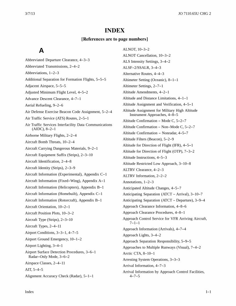
3/7/13 JO 7110.65U CHG 2
Index I−1
INDEX
[References are to page numbers]
AAbbreviated Departure Clearance, 4−3−3
Abbreviated Transmissions, 2−4−2
Abbreviations, 1−2−3
Additional Separation for Formation Flights, 5−5−5
Adjacent Airspace, 5−5−5
Adjusted Minimum Flight Level, 4−5−2
Advance Descent Clearance, 4−7−1
Aerial Refueling, 9−2−6
Air Defense Exercise Beacon Code Assignment, 5−2−4
Air Traffic Service (ATS) Routes, 2−5−1
Air Traffic Services Interfacility Data Communications(AIDC), 8−2−1
Airborne Military Flights, 2−2−4
Aircraft Bomb Threats, 10−2−4
Aircraft Carrying Dangerous Materials, 9−2−1
Aircraft Equipment Suffix (Strips), 2−3−10
Aircraft Identification, 2−4−8
Aircraft Identity (Strips), 2−3−9
Aircraft Information (Experimental), Appendix C−1
Aircraft Information (Fixed−Wing), Appendix A−1
Aircraft Information (Helicopters), Appendix B−1
Aircraft Information (Homebuilt), Appendix C−1
Aircraft Information (Rotorcraft), Appendix B−1
Aircraft Orientation, 10−2−1
Aircraft Position Plots, 10−3−2
Aircraft Type (Strips), 2−3−10
Aircraft Types, 2−4−11
Airport Conditions, 3−3−1, 4−7−5
Airport Ground Emergency, 10−1−2
Airport Lighting, 3−4−1
Airport Surface Detection Procedures, 3−6−1Radar−Only Mode, 3−6−2
Airspace Classes, 2−4−11
AIT, 5−4−5
Alignment Accuracy Check (Radar), 5−1−1
ALNOT, 10−3−2
ALNOT Cancellation, 10−3−2
ALS Intensity Settings, 3−4−2
ALSF−2/SSALR, 3−4−3
Alternative Routes, 4−4−3
Altimeter Setting (Oceanic), 8−1−1
Altimeter Settings, 2−7−1
Altitude Amendments, 4−2−1
Altitude and Distance Limitations, 4−1−1
Altitude Assignment and Verification, 4−5−1
Altitude Assignment for Military High AltitudeInstrument Approaches, 4−8−5
Altitude Confirmation − Mode C, 5−2−7
Altitude Confirmation − Non−Mode C, 5−2−7
Altitude Confirmation − Nonradar, 4−5−7
Altitude Filters (Beacon), 5−2−9
Altitude for Direction of Flight (IFR), 4−5−1
Altitude for Direction of Flight (OTP), 7−3−2
Altitude Instructions, 4−5−3
Altitude Restricted Low Approach, 3−10−8
ALTRV Clearance, 4−2−3
ALTRV Information, 2−2−2
Annotations, 1−2−3
Anticipated Altitude Changes, 4−5−7
Anticipating Separation (ATCT − Arrival), 3−10−7
Anticipating Separation (ATCT − Departure), 3−9−4
Approach Clearance Information, 4−8−6
Approach Clearance Procedures, 4−8−1
Approach Control Service for VFR Arriving Aircraft,7−1−1
Approach Information (Arrivals), 4−7−4
Approach Lights, 3−4−2
Approach Separation Responsibility, 5−9−5
Approaches to Multiple Runways (Visual), 7−4−2
Arctic CTA, 8−10−1
Arresting System Operations, 3−3−3
Arrival Information, 4−7−3
Arrival Information by Approach Control Facilities,4−7−5

3/7/13JO 7110.65U CHG 2
IndexI−2
[References are to page numbers]
Arrival Instructions (Radar), 5−9−2
Arrival Procedures, 4−7−1
Arrival Procedures and Separation (ATCT), 3−10−1
Arrivals on Parallel or Nonintersecting DivergingRunways (Radar), 5−8−3
ARTS, 5−15−1
ATC Assigned Airspace, 9−3−1
ATC Service, 2−1−1
ATIS Application, 2−9−1
ATIS Content, 2−9−2
ATIS Procedures, 2−9−1
Authorized Interruptions, 2−4−1
Authorized Relays, 2−4−2
Authorized Transmissions, 2−4−1
Automated Information Transfer, 5−4−5
Automated Radar Terminal Systems − Terminal,5−15−1
Automatic Altitude Reporting, 5−2−8
Automation − En Route, 5−14−1
Avoidance of Areas of Nuclear Radiation, 9−2−8
AWACS Special Flights, 9−2−9
BBalloons, Unmanned Free, 9−6−1
Beacon Code for Pressure Suit Flights and FlightsAbove FL 600, 5−2−4
Beacon Code Monitor, 5−2−5
Beacon Identification Methods, 5−3−1
Beacon Range Accuracy, 5−1−2
Beacon Systems, 5−2−1
Beacon Target Displacement, 5−5−6
Beacon Termination, 5−2−8
Below Minima Report by Pilot, 4−7−4
Braking Action, 3−3−2
Braking Action Advisories, 3−3−2
CCalm Wind Conditions, 2−6−4
Canadian Airspace Procedures, 12−1−1
Cancellation of Takeoff Clearance, 3−9−10
Caribbean ICAO Region, 8−8−1
Celestial Navigation Training, 9−2−1
Charted Visual Flight Procedures, 7−4−3
Circling Approach, 4−8−5
Class A Airspace Restrictions, 7−1−1
Class B Separation, 7−9−2
Class B Service Area (Terminal), 7−9−1
Class C Separation, 7−8−1
Class C Service (Terminal), 7−8−1
Clearance Beyond Fix, 4−6−2
Clearance Delivery Instructions, 4−2−1
Clearance for Visual Approach, 7−4−1
Clearance Information (Arrivals), 4−7−1
Clearance Items, 4−2−1
Clearance Items (Airfile), 4−2−3
Clearance Limit, 4−8−5
Clearance Prefix, 4−2−1
Clearance Relay, 4−2−1
Clearance Status (Strips), 2−3−10
Clearance to Holding Fix, 4−6−1
Clearance Void Times, 4−3−5
Closed Runway Information, 3−3−1
Closed Traffic, 3−10−8
Coast Tracks, 5−14−2
Communications Failure, 10−4−1
Communications Release (Approaches), 4−8−6
Composite Separation Minima (Oceanic), 8−9−2
Computer Entry of Assigned Altitude, 5−14−2
Computer Message Verification, 2−2−2
Conflict Alert (Host), 5−14−1
Conflict Alert/Mode C Intruder (MCI) (ARTS), 5−15−2
Constraints Governing Supplements and ProceduralDeviations, 1−1−2
Contact Approach, 7−4−3

3/7/13 JO 7110.65U CHG 2
Index I−3
[References are to page numbers]
Control Estimates, 8−1−1
Control Symbology (Strip), 2−3−12
Control Transfer, 2−1−7
Controller Initiated Coast Tracks, 5−14−2
Controller Pilot Data Link Communications (CPDLC),2−4−4, 4−5−4, 13−2−3
Coordinate Use of Airspace, 2−1−7
Coordination Between Local and Ground Controllers,3−1−2
Coordination with Receiving Facility (Departures),4−3−7
Course Definitions, 1−2−2
Crossing Altitude, 4−1−2
CVFP, 7−4−3
DDecision Support Tools, 13−1−1
Degree − Distance Route Definition for MilitaryOperations, 4−4−2
Delay Sequencing (Departures), 4−3−7
Department of Energy Special Flights, 9−2−1
Departure and Arrival (Radar Separation), 5−8−3
Departure Clearances, 4−3−1
Departure Control Instructions (ATCT), 3−9−2
Departure Delay Information (ATCT), 3−9−1
Departure Information (ATCT), 3−9−1
Departure Procedures, 4−3−1
Departure Procedures and Separation (ATCT), 3−9−1
Departure Restrictions, 4−3−5
Departure Terminology, 4−3−1
Departures on Parallel or Nonintersecting DivergingRunways (Radar), 5−8−3
Deviation Advisories (Protected Airspace), 5−1−4
Discrete Environment (Beacon), 5−2−1
Disseminating Weather Information, 2−6−4
DOE, 9−2−1
Duty Priority, 2−1−1
EE−MSAW, 5−14−1
Edge of Scope, 5−5−6
Electronic Attack (EA) Activity, 5−1−2
Electronic Cursor, 5−1−3
ELP Operations, 3−10−10
ELT, 10−2−3
Emergencies, 10−1−1
Emergencies Involving Military Fighter−Type Aircraft,10−1−2
Emergency Airport Recommendation, 10−2−6
Emergency Assistance, 10−2−1
Emergency Code Assignment, 5−2−3
Emergency Control Actions, 10−4−1
Emergency Landing Pattern (ELP) Operations, 3−10−10
Emergency Lighting, 3−4−1
Emergency Locator Transmitter Signals, 10−2−3
Emergency Obstruction Video Map, 10−2−6
Emergency Procedures (Oceanic), 10−6−1
Emergency Situations, 10−2−1
Emphasis for Clarity, 2−4−4
En Route Data Entries (Strips), 2−3−3
En Route Fourth Line Data Block Usage, 5−4−5
En Route Minimum Safe Altitude Warning, 5−14−1
En Route Sector Team Responsibilities, 2−10−1
Entry of Reported Altitude, 5−14−2
EOVM, 10−2−6
Equipment on Runways, 3−1−2
Establishing Two−Way Communications (Class D),3−1−6
Evasive Action Maneuvers, 9−2−9
Expeditious Compliance, 2−1−3
Experimental Aircraft Operations, 9−2−2
Explosive Cargo, 10−5−1
Explosive Detection K−9 Teams, 10−2−5
FFAA Research and Development Flights, 9−2−2

3/7/13JO 7110.65U CHG 2
IndexI−4
[References are to page numbers]
Facility Identification, 2−4−8
Failed Transponder in Class A Airspace, 5−2−6
Failure to Display Assigned Beacon Code, 5−2−5
False or Deceptive Communications, 2−4−1
Far Field Monitor (FFM) Remote Status Unit, 3−3−4
Final Approach Course Interception, 5−9−1
Final Approach Obstacle Clearance Surfaces (OCS),3−7−5
Fix Use, 4−1−2
Flight Check Aircraft, 9−1−1
Flight Direction Exceptions, 4−5−1
Flight Plans and Control Information, 2−2−1
Flight Progress Strips, 2−3−1
FLYNET, 9−2−2
Formation Flight Additional Separation, 5−5−5
Formation Flights, 2−1−6
Forward Departure Delay Information, 4−3−7
Forwarding Amended and UTM Data, 2−2−3
Forwarding Approach Information by NonapproachControl Facilities, 3−10−1
Forwarding Departure Times, 4−3−7
Forwarding Flight Plan Data Between U.S. ARTCCsand Canadian ACCs, 2−2−4
Forwarding Information, 2−2−1
Forwarding VFR Data, 2−2−1
Fuel Dumping, 9−4−1
Function Code Assignments, 5−2−2
GGPA 102/103 Correction Factor, 5−5−6
Ground Missile Emergencies, 10−7−1
Ground Operations, 3−7−4
Ground Operations When Volcanic Ash is Present,3−1−6
Ground Stop, 4−3−7
Ground Traffic Movement, 3−7−1
HHelicopter Arrival Separation, 3−11−3
Helicopter Departure Separation, 3−11−2
Helicopter Landing Clearance, 3−11−4
Helicopter Operations, 3−11−1
Helicopter Takeoff Clearance, 3−11−1
High Intensity Runway Lights, 3−4−4
High Speed Turnoff Lights, 3−4−5
Hijacked Aircraft, 10−2−2
HIRL, 3−4−4
HIRL Associated with MALSR, 3−4−4
HIRL Changes Affecting RVR, 3−4−4
HIWAS, 2−6−1
Hold for Release, 4−3−5
Holding Aircraft, 4−6−1
Holding Delays, 4−6−2
Holding Flight Path Deviation, 4−6−3
Holding Instructions, 4−6−3
Holding Pattern Surveillance, 5−1−4
Holding Points (Visual), 4−6−3
IICAO Phonetics, 2−4−5
IFR − VFR Flights, 4−2−3
IFR Flight Progress Data, 2−2−1
IFR to VFR Flight Plan Change, 2−2−1
ILS Protection/Critical Areas (Holding), 4−6−3
Inflight Deviations from Transponder/Mode CRequirements Between 10,000 Feet and 18,000Feet, 5−2−8
Inflight Equipment Malfunctions, 2−1−4
Inhibiting Low Altitude Alert System (TPX−42),5−16−1
Inhibiting Minimum Safe Altitude Warning (ARTS),5−15−2
Initial Heading, 5−8−1
Inoperative Interrogator, 5−2−6
Inoperative/Malfunctioning Transponder, 5−2−5

3/7/13 JO 7110.65U CHG 2
Index I−5
[References are to page numbers]
Interceptor Operations, 9−2−4
Interfacility Automated Information Transfer, 5−4−5
Interphone Message Format, 2−4−3
Interphone Message Termination, 2−4−4
Interphone Transmission Priorities, 2−4−2
Intersecting Runway Separation (Arrival), 3−10−3
Intersecting Runway Separation (Departure), 3−9−7
JJettisoning of External Stores, 9−5−1
KK−9 Teams, 10−2−5
LLAAS, 5−16−1
Landing Area Condition, 3−3−1
Landing Clearance, 3−10−6
Landing Clearance Without Visual Observation, 3−10−7
Landing Information (ATCT), 3−10−1
Lateral Separation (Nonradar), 6−5−1
Lateral Separation (Oceanic), 8−4−1
Law Enforcement Operations by Civil and MilitaryOrganizations, 9−2−5
Light Signals (ATCT), 3−2−1
Line Up and Wait (LUAW), 3−9−2
Longitudinal Separation (Nonradar), 6−4−1
Longitudinal Separation (Oceanic), 8−3−1
Low Approach, 4−8−7
Low Level Wind Shear/Microburst Advisories, 3−1−3
Lowest Usable Flight Level, 4−5−2
MMach Number Technique, 8−3−2
Malfunctioning Interrogator, 5−2−6
MALSR/ODALS, 3−4−2
Man−Portable Air Defense Systems (MANPADS) Alert,10−2−5
Manual Input of Computer Assigned Beacon Codes,2−2−2
Medium Intensity Runway Lights, 3−4−4
Merging Target Procedures, 5−1−3
Military DVFR Departures, 2−2−1
Military Operations above FL 600, 9−2−7
Military Procedures, 2−1−6
Military Single Frequency Approaches, 5−10−5
Military Special Use Frequencies, 9−2−8
Military Training Routes, 9−2−2
Minimum En Route Altitudes, 4−5−2
Minimum Fuel, 2−1−4
MIRL, 3−4−4
Missed Approach, 4−8−6
Missed Approach (Radar Approach), 5−10−4
Mixed Environment (Beacon), 5−2−1
Mode C Intruder Alert (Host), 5−14−1
Monitoring Radios, 2−4−1
MSAW, 5−15−2
NNAVAID Fixes, 2−5−2
NAVAID Malfunctions, 2−1−5
NAVAID Terms, 2−5−1
NAVAID Use Limitations, 4−1−1
Navy Fleet Support Missions, 10−5−1
No−Gyro Approach, 5−10−2
Nondiscrete Environment (Beacon), 5−2−1
Nonradar, 6−1−1
Nonradar Initial Separation of Departing and ArrivingAircraft, 6−3−1
Nonradar Initial Separation of Successive DepartingAircraft, 6−2−1
Nonradar Timed Approaches, 6−7−1
Nonstandard Formation/Cell Operations, 9−2−10
NORAD Special Flights, 9−2−9

3/7/13JO 7110.65U CHG 2
IndexI−6
[References are to page numbers]
North American ICAO Region, 8−10−1
North American Route Program (NRP), 2−2−5
North Atlantic ICAO Region, 8−7−1
Notes, 1−2−2
Number Clarification, 2−4−7
Numbers Usage, 2−4−5
OObserved Abnormalities, 3−1−5
Obstruction Lights, 3−4−5
Ocean21 ATC System, 13−2−1
Oceanic Coordination, 8−2−1
Oceanic Data Entries, 2−3−5
Oceanic Navigational Error Reporting (ONER)Procedures, 8−1−1
Oceanic Procedures, 8−1−1
Oceanic Separation, 8−1−1
Oceanic Transition Procedures, 8−5−1
Oceanic VFR Flight Plans, 8−1−1
Offshore Procedures, 8−1−1
Offshore Transition Procedures, 8−5−1
Open Skies Treaty Aircraft, 9−2−10
Operational Priority, 2−1−2
Operational Requests, 2−1−9
Overdue Aircraft, 10−3−1
Overhead Maneuver, 3−10−8
PPacific ICAO Region, 8−9−1
PAR Approaches − Terminal, 5−12−1
Parachute Operations, 9−7−1
Parallel Dependent ILS/MLS Approaches, 5−9−7
Passing or Diverging, 5−5−4
Personnel on Runways, 3−1−2
Pilot Acknowledgment/Read Back, 2−4−1
PIREP Information, 2−6−1
Point Out, 5−4−4
Position Determination (Airports), 3−1−2
Position Information (Radar), 5−3−2
Position Report (Oceanic), 8−1−1
Position Reporting (Radar), 5−1−4
Position Responsibilities, 2−10−1
Practice Approaches, 4−8−6
Practice Precautionary Approaches, 3−10−10
Prearranged Coordination, 5−4−5
Precision Approach Critical Area, 3−7−4
Precision Approach Path Indicators (PAPI), 3−4−1
Precision Obstacle Free Zone (POFZ), 3−7−5
Preventive Control (Airports), 3−1−1
Primary Radar Identification Methods, 5−3−1
Priority Interruptions, 2−4−2
Procedural Letters of Agreement, 1−1−2
Procedural Preference, 2−1−1
QQuestionable Identification, 5−3−2
RRadar Approaches − Terminal, 5−10−1
Radar Arrivals, 5−9−1
Radar Beacon Changes for Military Aircraft, 4−7−2
Radar Beacon Code Changes, 5−2−2
Radar Departures, 5−8−1
Radar Fix Posting, 5−1−4
Radar Identification, 5−3−1
Radar Identification Status, 5−3−2
Radar Presentation and Equipment Performance, 5−1−1
Radar Separation, 5−5−1
Radar Separation Application, 5−5−1
Radar Separation Minima, 5−5−2
Radar Separation Vertical Application, 5−5−3
Radar Service Limitations, 5−1−3
Radar Service Termination, 5−1−4

3/7/13 JO 7110.65U CHG 2
Index I−7
[References are to page numbers]
Radar Use, 5−1−1
Radar−Only Mode, 3−6−2
Radio and Interphone Communications, 2−4−1
Radio Communications, 2−1−7, 2−4−1
Radio Failure (Beacon), 5−2−3
Radio Frequency Changes for Military Aircraft, 4−7−2
Radio Message Format, 2−4−2
Receiver−Only Acknowledgment (ATCT), 3−2−1
Receiving Controller Handoff, 5−4−3
Recording Information, 2−2−1
Reduced Vertical Separation Minimum (RVSM),2−1−12
Reduction of Route Protected Airspace (Oceanic),8−4−3
References, 1−2−3
REIL, 3−4−1
Relayed Approach Clearance, 4−8−5
Release Times, 4−3−5
Reporting Essential Flight Information, 2−1−4
Reporting Weather Conditions, 2−6−4
Responsibility Transfer to RCC, 10−3−2
Rotating Beacon, 3−4−5
Route Amendments, 4−2−1
Route and NAVAID Description, 2−5−1
Route Assignment, 4−4−1
Route Structure Transitions, 4−4−2
Route Use, 4−4−1
Routes in Class G Airspace, 4−4−3
Runway Centerline Lights, 3−4−4
Runway Edge Lights, 3−4−3
Runway End Identifier Lights, 3−4−1
Runway Exiting, 3−10−7
Runway Proximity, 3−7−4
Runway Selection, 3−5−1
RVR/RVV, 2−8−1
RVSM, 2−1−12
SSafety Alert, 2−1−3
Safety Management System (SMS), 1−1−2
Same Runway Separation (Arrival), 3−10−2
Same Runway Separation (Departure), 3−9−4
SAR, 10−3−1
SAR Information to be Forwarded to ARTCC, 10−3−1
SAR Information to be Forwarded to RCC, 10−3−1
Sea Lane Operations, 3−12−1
Search and Rescue, 10−3−1
Sector Eligibility, 5−14−2
Security Notice (SECNOT), 9−2−5
Selected Altitude Limits, 5−14−2
Separation from Airspace Reservations, 8−6−1
Separation from Obstructions, 5−5−5
Sequence/Spacing Application, 3−8−1
Sequenced Flashing Lights, 3−4−2
SFA, 4−7−1
Side−Step Maneuver, 4−8−6
Simulated Flameout (SFO) Approaches, 3−10−10
Simultaneous Approach and Runway Edge LightOperation, 3−4−4
Simultaneous Departures (Radar), 5−8−1
Simultaneous Independent Dual ILS/MLS Approaches− High Update Radar, 5−9−9
Simultaneous Independent ILS/MLS Approaches −Dual & Triple, 5−9−8
Simultaneous Landings or Takeoffs (Helicopter),3−11−3
Simultaneous Offset Instrument Approaches (SOIA)−High Update Radar, 5−9−11
Simultaneous Opposite Direction Operation, 3−8−2
Simultaneous Same Direction Operation, 3−8−1
Single Frequency Approaches, 4−7−1
Spacing and Sequencing (ATCT), 3−8−1
Special Flights, 9−1−1
Special Interest Sites, 9−2−4
Special Operations, 9−2−1
Special Use Airspace, 9−3−1

3/7/13JO 7110.65U CHG 2
IndexI−8
[References are to page numbers]
Special VFR, 7−5−1
Specifying Altitude (Approaches), 4−8−5
Speed Adjustment, 5−7−1
Speed Adjustment Minima, 5−7−3
Speed Adjustment Termination, 5−7−3
Standby or Low Sensitivity Operation, 5−2−5
STOL Runways, 3−5−1
Stop−and−Go Low Approach, 3−8−1
Successive Departures (Radar), 5−8−1
Surface Area Restrictions, 3−1−5
Surface Areas, 2−1−7
Surveillance Approaches − Terminal, 5−11−1
SVFR, 7−5−1
Switching ILS/MLS Runways, 4−7−6
TTailwind Components, 3−5−1
Takeoff Clearance, 3−9−9
Target Markers, 5−3−3
Target Resolution, 5−5−1
Target Separation, 5−5−1
Taxi and Ground Movement Operations, 3−7−2
Taxi and Ground Movement Procedures, 3−7−1
Taxiway Lights, 3−4−5
Teletype Flight Data Format − U.S. ARTCCs −Canadian ACCs, 2−2−4
Temporary Moving Airspace Reservations, 8−6−1
Temporary Stationary Airspace Reservations, 8−6−1
Terminal Automation Systems Identification Methods,5−3−2
Terminal Data Entries (Strips), 2−3−6
Terminal Radar Service Area, 7−7−1
Terminal Radar/Nonradar Team PositionResponsibilities, 2−10−2
Terrain Awareness Warning System (TAWS) Alerts,2−1−13
Through Clearances, 4−2−3
Timely Information (ATCT), 3−3−1
Touch−and−Go Approach, 4−8−7
Touch−and−Go Low Approach, 3−8−1
Touchdown Zone Lights, 3−4−4
Tower Team Position Responsibilities, 2−10−4
TPX−42 − Terminal, 5−16−1
Track Separation (Oceanic), 8−4−4
Track Suspend Function (ARTS), 5−15−2
Traffic Advisories, 2−1−9
Traffic Information (Airports), 3−1−2
Traffic Management Procedures, 11−1−1
Transfer of Jurisdiction, 4−7−4
Transfer of Position (SOP), Appendix D−1
Transfer of Radar Identification, 5−4−1
Transfer of Radar Identification − Methods, 5−4−1
Transfer of Radar Identification − Terms, 5−4−1
Transfer of Radar Identification − Traffic, 5−4−2
Transferring Controller Handoff, 5−4−2
Transmit Proposed Flight Plan, 2−2−3
TRSA, 7−7−1
TRSA Separation, 7−7−1
UUnauthorized Laser Illumination of Aircraft, 2−9−2,
10−2−6
Unidentified Flying Object (UFO) Reports, 9−8−1
Unmanned Free Balloons, 9−6−1
Unmonitored NAVAIDs (Holding), 4−6−3
Unsafe Runway Information, 3−3−1
USAF/USN Undergraduate Pilots (Strips), 2−3−10
Use of Active Runways, 3−1−1
Use of MARSA, 2−1−5
Use of PAR for Approach Monitoring − Terminal,5−13−1
Use of Tower Radar Displays, 3−1−5
User Request Evaluation Tool (URET), 13−1−1
VValidation of Mode C Readout, 5−2−6

3/7/13 JO 7110.65U CHG 2
Index I−9
[References are to page numbers]
VASI, 3−4−1
Vectoring, 5−6−1
Vectors Across Final Approach Course, 5−9−2
Vectors Below Minimum Altitude, 5−6−2
Vectors for Visual Approach, 7−4−1
Vectors to Final Approach Course, 5−9−1
Vehicles on Runways, 3−1−2
Vertical Application Exceptions, 5−5−4
Vertical Separation (Nonradar), 6−6−1
Vertical Separation Minima, 4−5−1
VFR − IFR Flights, 4−2−3
VFR Aircraft in Weather Difficulty, 10−2−2
VFR Basic Radar Service (Terminal), 7−6−1
VFR Code Assignments, 5−2−3
VFR Conditions, 7−1−1
VFR Release of IFR Departure, 4−3−7
VFR−on−top, 7−3−1
VFR−on−top (NAVAID Use), 4−1−2
Visual, 7−1−1
Visual Approach Slope Indicators, 3−4−1
Visual Approaches, 7−4−1
Visual Holding of VFR Aircraft, 7−1−1
Visual Separation, 7−2−1
Visual Signals (ATCT), 3−2−1
Visually Scanning Runways, 3−1−6
Volcanic Ash, 10−2−7
WWake Turbulence, 2−1−9
Wake Turbulence Cautionary Advisories, 2−1−9
Wake Turbulence Separation for IntersectionDepartures, 3−9−6
Warning Signal (ATCT), 3−2−1
Washington, DC, Special Flight Rules Area (DCSFRA), 9−2−4
Weather and Chaff Services, 2−6−2
Weather Deviations, 8−9−4
Weather Deviations in North Atlantic (NAT) Airspace,8−7−2
Weather Familiarization, 2−6−1
Weather Information, 2−6−1
Weather Information (Arrivals), 4−7−3
Weather Reconnaissance Flights, 9−2−9
Withholding Landing Clearance, 3−10−7
Word Meanings, 1−2−1
Words and Phrases (Communications), 2−4−4


Federal AviationAdministration
JO 7110.65U CHG 23/7/13
Initiated By: AJV−0Vice President, Mission Support Services
BRIEFING GUIDE
U.S. DEPARTMENT OF TRANSPORTATIONFEDERAL AVIATION ADMINISTRATION


3/7/13JO 7110.65U CHG 2
Briefing GuideBG−2
Table of Contents
ParagraphNumber
Title Page
2−1−6 SAFETY ALERT . . . . . . . . . . . . . . . . . . . . . . . . . . . . . . . . . . . . . . . . . . . 3
2−1−30 “BLUE LIGHTING” EVENTS . . . . . . . . . . . . . . . . . . . . . . . . . . . . . . . . 4
4−5−6 MINIMUM EN ROUTE ALTITUDES . . . . . . . . . . . . . . . . . . . . . . . . . . . . . 4
5−2−17 VALIDATION OF MODE C READOUT . . . . . . . . . . . . . . . . . . . . . . . . 5
9−2−7 IFR MILITARY TRAINING ROUTES . . . . . . . . . . . . . . . . . . . . . . . . . 11
5−5−4 MINIMA . . . . . . . . . . . . . . . . . . . . . . . . . . . . . . . . . . . . . . . . . . . . . . . . . 5
5−8−2 INITIAL HEADING . . . . . . . . . . . . . . . . . . . . . . . . . . . . . . . . . . . . . . . . 6
7−2−1 VISUAL SEPARATION . . . . . . . . . . . . . . . . . . . . . . . . . . . . . . . . . . . . . 7
7−4−4 APPROACHES TO MULTIPLE RUNWAYS . . . . . . . . . . . . . . . . . . . . 10
APPENDIX A AIRCRAFT INFORMATION FIXED WING AIRCRAFT . . . . . . . . . . 12

3/7/13 JO 7110.65U CHG 2
Briefing Guide BG−3
1. PARAGRAPH NUMBER AND TITLE: 2−1−6. SAFETY ALERT
2. BACKGROUND: Phraseology for issuing a low altitude alert includes providing the applicable altitudebased on either the aircraft’s location and/or activity. RNAV instrument approaches such as LPV DA,LNAV/VNAV DA, and LNAV MDA, all indicate different altitudes for their respective Decision Altitude (DA),Minimum Descent Altitude (MDA), or Decision Height (DH) based on several factors (for example, approachcategory, inoperative equipment (aircraft or ground), crew qualifications, and company authorization). These areall examples of issues that may either limit or change the height of a published MDA, DA or DH. Controllers maynot be aware of these restrictions and are only required to clear an aircraft for the type of approach that is listed onthe approach plate (for example, “(Callsign) Cleared RNAV Runway 35C approach”). Therefore, providing thecorrect DA, MDA, or DH to the pilot quickly and accurately is largely precluded.
3. CHANGE:
OLD NEW2-1-6. SAFETY ALERT 2-1-6. SAFETY ALERTIssue a safety alert to an aircraft if you are aware theaircraft is in a position/altitude which, in yourjudgment, places it in unsafe proximity to terrain,obstructions, or other aircraft. Once the pilotinforms you action is being taken to resolve thesituation, you may discontinue the issuance offurther alerts. Do not assume that because someoneelse has responsibility for the aircraft that the unsafesituation has been observed and the safety alertissued; inform the appropriate controller.
Issue a safety alert to an aircraft if you are aware theaircraft is in a position/altitude that, in yourjudgment, places it in unsafe proximity to terrain,obstructions, or other aircraft. Once the pilotinforms you action is being taken to resolve thesituation, you may discontinue the issuance offurther alerts. Do not assume that because someoneelse has responsibility for the aircraft that the unsafesituation has been observed and the safety alertissued; inform the appropriate controller.
NOTE No Change
a. Terrain/Obstruction Alert. Immediatelyissue/initiate an alert to an aircraft if you are awarethe aircraft is at an altitude which, in your judgment,places it in unsafe proximity to terrain/obstructions.Issue the alert as follows:
a. Terrain/Obstruction Alert. Immediatelyissue/initiate an alert to an aircraft if you are awarethe aircraft is at an altitude that, in your judgment,places it in unsafe proximity to terrain and/orobstructions. Issue the alert as follows:
PHRASEOLOGY−LOW ALTITUDE ALERT (call sign),CHECK YOUR ALTITUDE IMMEDIATELY.
PHRASEOLOGY−LOW ALTITUDE ALERT (call sign),CHECK YOUR ALTITUDE IMMEDIATELY.
Add and, if the aircraft is not yet on final approach,
THE (as appropriate) MEA/MVA/MOCA/MIA INYOUR AREA IS (altitude),
THE (as appropriate) MEA/MVA/MOCA/MIA INYOUR AREA IS (altitude),
or if an aircraft is past the final approach fix (non-pre-cision approach),
Delete
or the outer marker, Delete
or the fix used in lieu of the outer marker (precisionapproach),
Delete
and, if known, issue Delete
THE (as appropriate) MDA/DH IS (altitude). Delete
Add REFERENCE−P/CG Term – Final Approach - IFR

3/7/13JO 7110.65U CHG 2
Briefing GuideBG−4
b. Aircraft Conflict/Mode C Intruder Alert.Immediately issue/initiate an alert to an aircraft ifyou are aware of another aircraft at an altitudewhich you believe places them in unsafe proximity.If feasible, offer the pilot an alternate course ofaction.
b. Aircraft Conflict/Mode C Intruder Alert.Immediately issue/initiate an alert to an aircraft ifyou are aware of another aircraft at an altitudewhich you believe places them in unsafe proximity.If feasible, offer the pilot an alternate course ofaction. When an alternate course of action isgiven, end the transmission with the word“immediately.”
c. When an alternate course of action is given, endthe transmission with the word “immediately.”
Delete
PHRASEOLOGY− No Change
Add EXAMPLE−“Traffic Alert, Cessna Three Four Juliet, advise youturn left immediately.”
Add or
Add “Traffic Alert, Cessna Three-Four Juliet, advise youturn left and climb immediately.”
1. PARAGRAPH NUMBER AND TITLE: 2−1−30. “BLUE LIGHTNING” EVENTS
2. BACKGROUND: Human smuggling is a global problem that is growing in frequency and scope. Thecriminal organizations behind the major smuggling rings have often utilized commercial air transportation tomove their victims from country to country, or from continent to continent. The Secretaries of the Department ofTransportation and Department of Homeland Security (DHS) have committed their departments (including theFAA) to provide a process intended to allow aircrews to notify the appropriate law enforcement agency about apossible human smuggling event on an air carrier flight inbound to the United States. Passing the information onATC frequencies would only occur if the primary means (through company channels) of notification have failed.
3. CHANGE:
OLD NEWAdd 2-1-30. “BLUE LIGHTNING” EVENTSAdd Ensure that the supervisor/controller-in-charge
(CIC) is notified of reports of possible humantrafficking. These may be referred to as “BlueLightning” events.
1. PARAGRAPH NUMBER AND TITLE: 4−5−6. MINIMUM EN ROUTE ALTITUDES
2. BACKGROUND: Since 2002, Global Positioning Systems/Wide Area Augmentation System(GPS/WAAS) Minimum En Route Altitudes (MEA) have been certified on some low altitude Air Traffic Service(ATS) routes, mostly in Alaska. Global Navigation Satellite System (GNSS) equipped aircraft are equipped withGPS or WAAS, with en route and terminal capability. The GNSS MEA allows appropriately-equipped GNSSaircraft to fly at altitudes lower than conventional MEAs when there are restrictions due to NAVAID coverage.When established on Victor airways, the GNSS MEA provides an advantage to pilots by allowing flight belowpotential adverse weather conditions (i.e., icing conditions or other) where conventional MEAs may be restricted

3/7/13 JO 7110.65U CHG 2
Briefing Guide BG−5
due to NAVAID coverage. The GNSS MEA on a Victor airway provides air traffic control an advantage bymaking additional cardinal altitudes available on the airway. GNSS MEAs are also published on low altitudeTango or “T” routes, high altitude Q routes as well as jet routes. No guidance was previously published regardingGNSS MEAs. For the purpose of this change, all previously designated routes are termed ATS routes as definedin the Pilot/Controller Glossary. The GNSS MEA is for use in the 48 contiguous states only, Alaska requirementsremain unchanged.
3. CHANGE:
OLD NEW4-5-6. MINIMUM EN ROUTE ALTITUDES 4-5-6. MINIMUM EN ROUTE ALTITUDES
Title thru c No Change
Add d. GNSS MEAs may be approved on publishedATS routes. Air traffic may assign GNSS MEAsto GNSS-equipped aircraft where established.
Add NOTE–
On high altitude ATS routes, the GNSS MEA is
FL180 unless published higher.
d Re-letter e
1. PARAGRAPH NUMBER AND TITLE: 5−2−17. VALIDATION OF MODE C READOUT
2. BACKGROUND: The Pilot Controller Glossary (PCG) correctly defines the term ”verify” to mean”Request confirmation of information.” The PCG also correctly leaves out the term ”confirm.” Throughout theorder, the term ”verify” is correctly used in examples of phraseology when the intent of the phraseology is to”confirm” information. This change identifies an instances where the term is not used.
3. CHANGE:
OLD NEW5-2-17. VALIDATION OF MODE C READOUT 5-2-17. VALIDATION OF MODE C READOUT
Title through d No Change
1.Confirm that the pilot is using 29.92 inches ofmercury as the altimeter setting and has accuratelyreported the altitude.
1.Verify that the pilot is using 29.92 inches ofmercury as the altimeter setting and has accuratelyreported the altitude.
PHRASEOLOGY−CONFIRM USING TWO NINER NINER TWO ASYOUR ALTIMETER SETTING.
PHRASEOLOGY−VERIFY USING TWO NINER NINER TWO AS YOURALTIMETER SETTING.
1. PARAGRAPH NUMBER AND TITLE: 5−5−4. MINIMA
2. BACKGROUND: At the request of Terminal Operations, Headquarters, FAA Flight Systems Laboratoryconducted an analytical study to re-examine the separation standards that are applicable to terminal use of theASR-11. This study addressed several paragraphs in FAA Order JO 7110.65, Chapter 5, Section 5, RadarSeparation, including target separation, target resolution, vertical application, rules on the use of passing anddiverging, the minimum separation from obstructions, minimum separation from adjacent airspace, and, ifapplicable, edge-of-scope separation. The performance of the ASR-11 with MSSR was compared against the

3/7/13JO 7110.65U CHG 2
Briefing GuideBG−6
performance of similar systems, specifically ASR-9 with Mode S, that are currently allowed to be used for theseoperations. The study concluded that performance of the ASR-11 (MSSR) is equivalent to the performance of anASR-9 with Mode S. Therefore, allowing the use of the terminal separation standard minima of 3 NM forproperly performing transponder-equipped aircraft at ranges from the radar of up to 60 NM from the sensorantenna should incur no greater risk or hazard than the current separation standard minima. There are currently 68ASR-11 radar systems installed in the National Airspace System (NAS). Increasing the usability of the existinginstalled infrastructure provided by the ASR-11 will increase the efficiency of the NAS, with no impact on overallsafety.
3. CHANGE:
OLD NEW554. MINIMA 554. MINIMA
Title thru a3 No Change
Add 4. For single sensor ASR-11 MSSR Beacon,when less than 60 miles from the antenna–3 miles.
NOTE−
Wake turbulence procedures specify increased separation minima required for certain classes of aircraft because of the possible effects of wake turbulence.
NOTE−
Wake turbulence procedures specify increased separation minima required for certain classes of aircraft because of the possible effects of wake turbulence.
1. PARAGRAPH NUMBER AND TITLE: 5−8−2. INITIAL HEADING
2. BACKGROUND: The Air Traffic Control Procedures and Phraseology Action Team (ATCPP) is a workinggroup under the Performance Based Operations Aviation Rulemaking Committee (PARC) established to addressRNAV and required navigation performance implementation issues and propose action to the FAA. The ATCPPis composed of air traffic, aviation industry, and human factors subject matter experts. The ATCPP reviews,assesses, and proposes changes to ATC procedures and phraseology and is tasked with incorporating thosechanges into FAA Order JO 7110.65, the AIM, and AIP.Extensive evaluation of RNAV SIDs that begin at the runway has established that aircraft have occasionallyflown an unexpected flight path on departure due to loading of an incorrect procedure in the Flight ManagementSystem (FMS). Pilots enter the departure procedure and route of flight received in the ATC clearance prior todeparture from the gate area. RNAV SIDs are recalled from a database for entry into the FMS. Runway specificRNAV SIDs may be programmed into the FMS based on the anticipated departure runway. Human error mayresult in an incorrect procedure being recalled from the database, or the runway assignment on taxi may not becoincident with the RNAV SID or transition. However, human factors studies have established that there isgreater potential for an incorrect procedure to be entered in the FMS when a change in the procedure entered inthe FMS is required after departure from the gate. Extensive evaluation of procedure implementations and fieldtesting of various runway verification phraseology has established that an ATC advisory to pilots prior todeparture can assist aircrew in ensuring the correct departure procedure is entered in the FMS. The phraseologyin this change has been demonstrated successfully at Dallas/Fort Worth International, Charlotte/DouglasInternational, and Hartsfield-Jackson Atlanta International airports.
3. CHANGE:
OLD NEW5-8-2. INITIAL HEADING 5-8-2. INITIAL HEADING
Before departure, assign the initial heading to beflown if a departing aircraft is to be vectoredimmediately after takeoff.
a. Before departure, assign the initial heading tobe flown if a departing aircraft is to be vectoredimmediately after takeoff.

3/7/13 JO 7110.65U CHG 2
Briefing Guide BG−7
Phraseology thru Reference No Change
Add b. When conducting simultaneous parallelrunway departures utilizing RNAV SIDs, adviseaircraft of the initial fix/waypoint on the RNAVroute.
Add PHRASEOLOGY−RNAV to (fix/waypoint), RUNWAY (number),CLEARED FOR TAKEOFF.
Add EXAMPLE−“RNAV to MPASS, Runway Two-Six Left, cleared fortakeoff.”
Add NOTE-1. TERMINAL. A purpose for an initial waypoint ad-visory is not necessary since pilots associate this advis-ory with the flight path to their planned route of flight.Pilots must immediately advise ATC if a different RNAVSID is entered in the aircraft FMS.
Add 2. The SID transition is not restated as it is contained inthe ATC clearance.
Add 3. Aircraft cleared via RNAV SIDs designed to beginwith a vector to the initial waypoint are assigned a head-ing before departure.
Add REFERENCE−FAAO JO 7110.65, Para 3-9-9, Takeoff ClearanceFAAO JO 7110.65, Para 4-3-2, Departure ClearancesAIM, Para 5−2−7. Departure Control
1. PARAGRAPH NUMBER AND TITLE: 7-2-1. VISUAL SEPARATION
2. BACKGROUND: Current air traffic procedures specify that visual separation may be applied betweenaircraft under the control of the same facility within the terminal area. With the advent of consolidated air trafficcontrol facilities, this restriction has limited the ability to apply the procedure as the radar facility is no longer “thesame facility” even though there have been minor or no changes to the airspace or operation. Additionally,controllers are required to advise the pilot if aircraft are on converging courses during the initial trafficdescription, along with the direction of the other aircraft.
3. CHANGE:
OLD NEW7-2-1. VISUAL SEPARATION 7-2-1. VISUAL SEPARATION
Title thru REFERENCE No Change
a. TERMINAL. Visual separation may be appliedbetween aircraft under the control of the samefacility within the terminal area up to but notincluding FL180 provided:
a. TERMINAL. Visual separation may be appliedbetween aircraft up to but not including FL180under the following conditions:
Add 1. Tower-applied visual separation.1. Communication is maintained with at least
one of the aircraft involved or the capability tocommunicate immediately as prescribed in para3-9-3, Departure Control Instructions, subpara a2 isavailable, and:
(a) Maintain communication with at least oneof the aircraft involved or ensure there is an abilityto communicate immediately as prescribed inparagraph 3-9-3, Departure Control Instructions,subparagraph a2.

3/7/13JO 7110.65U CHG 2
Briefing GuideBG−8
2. The aircraft are visually observed by the towerand visual separation is maintained between theaircraft by the tower. The tower must not providevisual separation between aircraft when waketurbulence separation is required or when the leadaircraft is a B757.
(b) The tower visually observes the aircraft,issues timely traffic advisories, and maintainsvisual separation between the aircraft. The use oftower-applied visual separation is not authorizedwhen wake turbulence separation is required.
Add (c) Issue subsequent control instructions asnecessary to ensure continued separationbetween the applicable aircraft.
Add NOTE–Adjacent airports with operating ATCTs are not author-ized to apply visual separation between their traffic andthe other ATCT’s traffic.
Add 2. Pilot-applied visual separation.Add (a) Maintain communication with at least
one of the aircraft involved and ensure there isan ability to communicate with the otheraircraft.
3. A pilot sees another aircraft and is instructedto maintain visual separation from the aircraft asfollows:
(b) The pilot sees another aircraft and isinstructed to maintain visual separation from theaircraft as follows:
(a) Tell the pilot about the other aircraftincluding position, direction and, unless it isobvious, the other aircraft’s intention.
(1) Tell the pilot about the other aircraft. In-clude position, direction, and, unless it is obvious,the other aircraft’s intention.
(b) Obtain acknowledgment from the pilot thatthe other aircraft is in sight.
(2) Obtain acknowledgment from the pilotthat the other aircraft is in sight.
(c) Instruct the pilot to maintain visualseparation from that aircraft.
(3) Instruct the pilot to maintain visual separ-ation from that aircraft.
(d) Advise the pilot if the radar targets appearlikely to converge.
Delete
Add PHRASEOLOGY−TRAFFIC, (clock position and distance), (direction)BOUND, (type of aircraft), (intentions and other relev-ant information).
Add DO YOU HAVE IT IN SIGHT?
Add If the answer is in the affirmative,
Add MAINTAIN VISUAL SEPARATION.
NOTEIssue this advisory in conjunction with the instruction tomaintain visual separation, or thereafter if the controllersubsequently becomes aware that the targets are mer-ging.
Delete
(e) If the aircraft are on converging courses,inform the other aircraft of the traffic and that visualseparation is being applied.
Delete

3/7/13 JO 7110.65U CHG 2
Briefing Guide BG−9
(f) If the pilot advises he/she has the traffic insight and will maintain visual separation from it (thepilot must use that entire phrase), the controllerneed only “approve” the operation instead ofrestating the instructions.
(c) If the pilot advises he/she has the traffic insight and will maintain visual separation from it (thepilot must use that entire phrase), the controllerneed only “approve” the operation instead ofrestating the instructions.
PHRASEOLOGY−TRAFFIC, (clock position and distance), (direction)BOUND, (type of aircraft), (intentions and other relevantinformation).
PHRASEOLOGY−Delete
If applicable, Delete
ON CONVERGING COURSE. Delete
DO YOU HAVE IT IN SIGHT? Delete
If the answer is in the affirmative, Delete
MAINTAIN VISUAL SEPARATION. Delete
If the pilot advises he/she has the traffic in sight and willmaintain visual separation from it (pilot must use thatentire phrase):
Delete
APPROVED APPROVED
Add NOTE-Pilot-applied visual separation between aircraft isachieved when the controller has instructed the pilot tomaintain visual separation and the pilot acknowledgesor when the controller has approved pilot-initiated visu-al separation.
Add REFERENCE−FAAO JO 7110.65, Para 5-4-5, Transferring Controller Handoff
If aircraft are on converging courses, advise the otheraircraft:
(d) If the aircraft are on converging courses,inform the other aircraft of the traffic and thatvisual separation is being applied.
TRAFFIC, (clock position and distance), (direction)BOUND, (type of aircraft), HAS YOU IN SIGHT ANDWILL MAINTAIN VISUAL SEPARATION.
PHRASEOLOGY−TRAFFIC, (clock position and distance), (direction)BOUND, (type of aircraft), HAS YOU IN SIGHT ANDWILL MAINTAIN VISUAL SEPARATION.
Add (e) Advise the pilots if the radar targetsappear likely to merge.
Add NOTE-Issue this advisory in conjunction with the instructionto maintain visual separation, the advisory to the otheraircraft of the converging course, or thereafter if thecontroller subsequently becomes aware that the targetsare merging.
Add EXAMPLE−“Radar targets appear likely to merge.”
Add b. TERMINAL. Control of aircraftmaintaining visual separation may betransferred to an adjacent position/ sector/facility. Coordination procedures must bespecified in an LOA or facility directive.

3/7/13JO 7110.65U CHG 2
Briefing GuideBG−10
Add REFERENCE−FAAO JO 7210.3, Para 4-3-1, Letters of Agreement
Subparagraphs b thru c Renumber c thru d
1. PARAGRAPH NUMBER AND TITLE: 7-4-4. APPROACHES TO MULTIPLE RUNWAYS
2. BACKGROUND: In an effort to move towards proactive risk mitigation and the reduction of risk in theNAS, the Air Traffic Organization (ATO) adopted the Risk Analysis Process (RAP) from EUROCONTROL.The RAP tool, developed by EUROCONTROL, is used to quantify the level of risk present for any air trafficincident. RAP is a post-event investigation analysis process and is applied to events involving a loss of separationwith a measure of compliance of less than 66 percent. These events are known as Risk Analysis Events (RAEs).The RAP is a Safety Management System (SMS) process that assesses the risk of an RAE. A review of severalRAEs in the NAS indicted that approach clearances were being issued to aircraft at questionable times, such ashigh and fast on the downwind or base leg, which resulted in an overshoot of the extended runway centerline. Thiscaused a conflict with aircraft on approach to the other runway with both aircraft in a side-by-side belly-upsituation.
3. CHANGE:
OLD NEW7-4-4. APPROACHES TO MULTIPLERUNWAYS
7-4-4. APPROACHES TO MULTIPLERUNWAYS
a. All aircraft must be informed that approachesare being conducted to parallel/intersecting/converging runways. This may be accomplishedthrough use of the ATIS.
a. All aircraft must be informed that approachesare being conducted to parallel, intersecting, orconverging runways. This may be accomplishedthrough use of the ATIS.
b through c2 No Change
(a) Standard separation is provided until theaircraft are established on a heading which willintercept the extended centerline of the runway at anangle not greater than 30 degrees, and each aircrafthas been issued and the pilot has acknowledgedreceipt of the visual approach clearance.
(a) Standard separation is provided until theaircraft are established on a heading which willintercept the extended centerline of the runway at anangle not greater than 30 degrees, and each aircrafthas been issued and one pilot has acknowledgedreceipt of the visual approach clearance, and theother pilot has acknowledged receipt of thevisual or instrument approach clearance.
NOTE−The intent of the 30 degree intercept angle is to reduce thepotential for overshoots of the final, and precludeside-by-side operations with one or both aircraft in a“belly-up” configuration during the turn. Aircraft per-formance, speed, and the number of degrees of the turnto the final are factors to be considered by the controllerwhen vectoring aircraft to parallel runways.
NOTE−1. The intent of the 30 degree intercept angle is to reducethe potential for overshoots of the extended centerline ofthe runway and preclude side-by-side operations withone or both aircraft in a “belly-up” configuration duringthe turn. Aircraft performance, speed, and the number ofdegrees of the turn are factors to be considered when vec-toring aircraft to parallel runways.
Add 2. Variances between heading assigned to intercept theextended centerline of the runway and aircraft groundtrack are expected due to the effect of wind and coursecorrections after completion of the turn and pilotacknowledgment of a visual approach clearance.
Add REFERENCE−FAA Publication, Pilot’s Handbook of Aeronautical Knowledge,Chapter 15 “Effect of Wind.”

3/7/13 JO 7110.65U CHG 2
Briefing Guide BG−11
c2(b) through c3(c) No Change
Add (d) Each aircraft must be assigned headingswhich will allow the aircraft to intercept theextended centerline of the runway at an anglenot greater than 30 degrees.
Add NOTE−1. The intent of the 30 degree intercept angle is to re-duce the potential for overshoots of the extendedcenterline of the runway and preclude side-by-side op-erations with one or both aircraft in a “belly-up” con-figuration during the turn. Aircraft performance,speed, and the number of degrees of the turn are factorsto be considered when vectoring aircraft to parallel run-ways.
Add 2. Variances between heading assigned to intercept theextended centerline of the runway and aircraft groundtrack are expected due to the effect of wind and coursecorrections after completion of the turn and pilotacknowledgment of a visual approach clearance.
Add REFERENCE−FAA Publication, Pilot’s Handbook of Aeronautical Knowledge,Chapter 15 “Effect of Wind.
1. PARAGRAPH NUMBER AND TITLE: 9-2-7. IFR MILITARY TRAINING ROUTES
2. BACKGROUND: FAA JO 7110.65, Pilot Controller Glossary (PCG) correctly defines the term “VERIFY”to mean “Request confirmation of information.” The PCG also correctly leaves out the term “CONFIRM.”Throughout the order, the term “VERIFY” is correctly used in EXAMPLES or PHRASEOLOGY when theintent of the phraseology is to ”confirm” information. This change identifies an instances where the term is notused.
3. CHANGE:
OLD NEW9-2-7. IFR MILITARY TRAINING ROUTES 9-2-7. IFR MILITARY TRAINING ROUTES
Title thru e No ChangePHRASEOLOGY−(Call sign) CONFIRM YOUR EXIT FIX ESTIMATEAND REQUESTED ALTITUDE AFTER EXIT,and if applicable, THE NUMBER OF REENTRIES.
PHRASEOLOGY−(Call sign) VERIFY YOUR EXIT FIX ESTIMATE ANDREQUESTED ALTITUDE AFTER EXIT,and if applicable, THE NUMBER OF REENTRIES.

3/7/13JO 7110.65U CHG 2
Briefing GuideBG−12
1. PARAGRAPH NUMBER AND TITLE: Appendix A. AIRCRAFT INFORMATION FIXED WINGAIRCRAFT
2. BACKGROUND: FAA JO 7110.65 includes aircraft type designator and performance information. Thisinformation is currently a portion of the aircraft type designators that have been approved by the InternationalCivil Aviation Organization (ICAO), which is responsible for issuing aircraft type designators for use in air trafficcontrol. The FAA includes additional operational/procedural information such as FAA Weight Class, SameRunway Separation, and Land and Hold Short Operations (LAHSO) Grouping.
3. CHANGE:
OLD NEWAppendix A. AIRCRAFT INFORMATIONFIXED WING AIRCRAFT
Appendix A. AIRCRAFT INFORMATIONFIXED WING AIRCRAFT
See attachment
AERMACCHI SpA (Italy)(Also AGUSTA, SIAI MARCHETTI)
Action Model TypeDesignat-
or
Description Performance Information
Number & TypeEngines/Weight
Class
ClimbRate(fpm)
DescentRate(fpm)
SRSCat.
LAHSO
Group
Change MB−326 M326 1J/S IIIChange S−211 S211 1J/S III
BEECH AIRCRAFT COMPANY (USA)(Also CCF, COLEMILL, DINFIA, EXCALIBUR, FUJI, HAMILTON, JETCRAFTERS, RAYTHEON, SWEARINGEN, VOLPAR)
Action Model TypeDesignat-
or
Description Performance Information
Number & TypeEngines/Weight
Class
ClimbRate(fpm)
DescentRate(fpm)
SRSCat.
LAHSO
Group
Change 18 (turbine) B18T 2T/S 2,000 2,000 II 1
BOEING COMPANY (USA)(Also GRUMMAN, IAI, LOCKHEED-BOEING, MCDONNELL DOUGLAS, NORTHROP-GRUMMAN, ROHR)
Action Model TypeDesignat-
or
Description Performance Information
Number & TypeEngines/Weight
Class
ClimbRate(fpm)
DescentRate(fpm)
SRSCat.
LAHSO
Group
Add B747−8 B748 4J/H IIIDelete KC−135A Stratotanker (J57
engines)K35A 4J/H 2.500 3,000 III
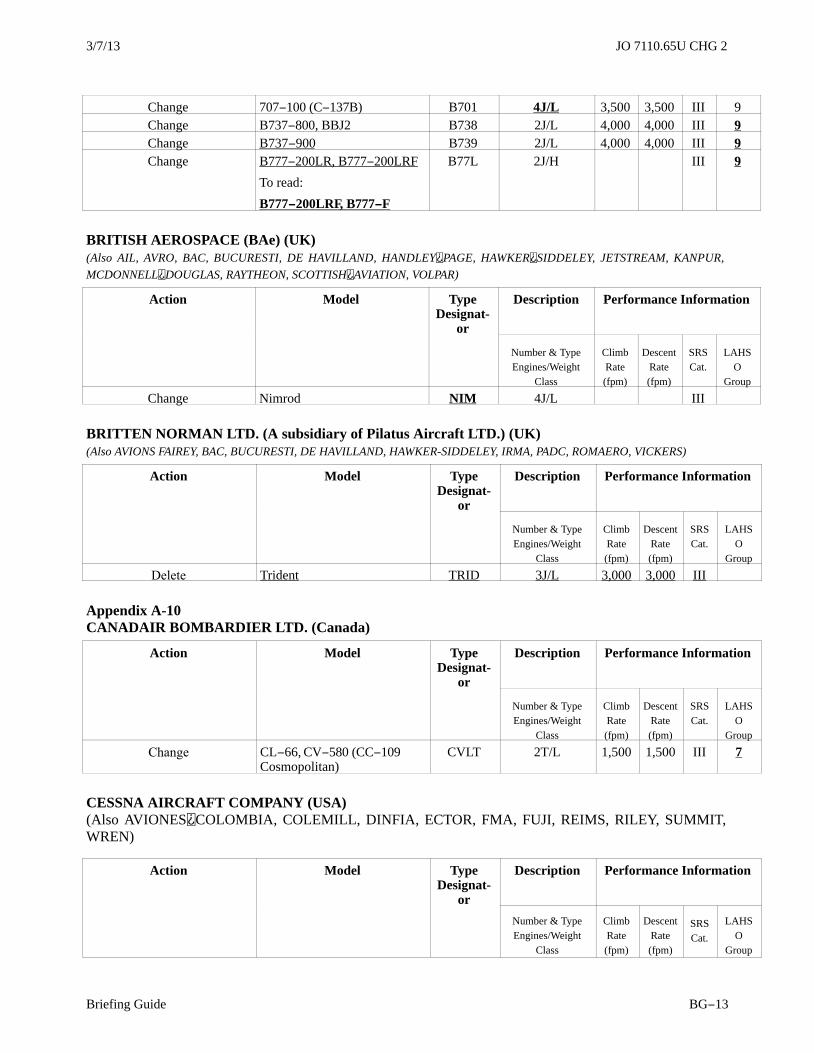
3/7/13 JO 7110.65U CHG 2
Briefing Guide BG−13
Change 707−100 (C−137B) B701 4J/L 3,500 3,500 III 9Change B737−800, BBJ2 B738 2J/L 4,000 4,000 III 9Change B737−900 B739 2J/L 4,000 4,000 III 9Change B777−200LR, B777−200LRF
To read:
B777−200LRF, B777−F
B77L 2J/H III 9
BRITISH AEROSPACE (BAe) (UK)(Also AIL, AVRO, BAC, BUCURESTI, DE HAVILLAND, HANDLEY PAGE, HAWKER SIDDELEY, JETSTREAM, KANPUR,
MCDONNELL DOUGLAS, RAYTHEON, SCOTTISH AVIATION, VOLPAR)
Action Model TypeDesignat-
or
Description Performance Information
Number & TypeEngines/Weight
Class
ClimbRate(fpm)
DescentRate(fpm)
SRSCat.
LAHSO
Group
Change Nimrod NIM 4J/L III
BRITTEN NORMAN LTD. (A subsidiary of Pilatus Aircraft LTD.) (UK)(Also AVIONS FAIREY, BAC, BUCURESTI, DE HAVILLAND, HAWKER-SIDDELEY, IRMA, PADC, ROMAERO, VICKERS)
Action Model TypeDesignat-
or
Description Performance Information
Number & TypeEngines/Weight
Class
ClimbRate(fpm)
DescentRate(fpm)
SRSCat.
LAHSO
Group
Delete Trident TRID 3J/L 3,000 3,000 III
Appendix A-10CANADAIR BOMBARDIER LTD. (Canada)
Action Model TypeDesignat-
or
Description Performance Information
Number & TypeEngines/Weight
Class
ClimbRate(fpm)
DescentRate(fpm)
SRSCat.
LAHSO
Group
Change CL−66, CV−580 (CC−109Cosmopolitan)
CVLT 2T/L 1,500 1,500 III 7
CESSNA AIRCRAFT COMPANY (USA)(Also AVIONES COLOMBIA, COLEMILL, DINFIA, ECTOR, FMA, FUJI, REIMS, RILEY, SUMMIT,WREN)
Action Model TypeDesignat-
or
Description Performance Information
Number & TypeEngines/Weight
Class
ClimbRate(fpm)
DescentRate(fpm)
SRSCat.
LAHSO
Group
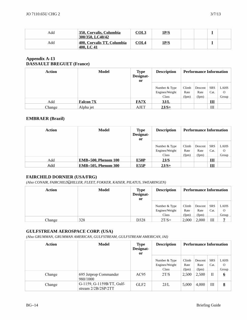
3/7/13JO 7110.65U CHG 2
Briefing GuideBG−14
Add 350, Corvalis, Columbia300/350, LC40/42
COL3 1P/S I
Add 400, Corvalis TT, Columbia400, LC 41
COL4 1P/S I
Appendix A-13DASSAULT BREGUET (France)
Action Model TypeDesignat-
or
Description Performance Information
Number & TypeEngines/Weight
Class
ClimbRate(fpm)
DescentRate(fpm)
SRSCat.
LAHSO
Group
Add Falcon 7X FA7X 3J/L IIIChange Alpha jet AJET 2J/S+ III
EMBRAER (Brazil)
Action Model TypeDesignat-
or
Description Performance Information
Number & TypeEngines/Weight
Class
ClimbRate(fpm)
DescentRate(fpm)
SRSCat.
LAHSO
Group
Add EMB−500, Phenom 100 E50P 2J/S IIIAdd EMB−505, Phenom 300 E55P 2J/S+ III
FAIRCHILD DORNIER (USA/FRG)(Also CONAIR, FAIRCHILD HILLER, FLEET, FOKKER, KAISER, PILATUS, SWEARINGEN)
Action Model TypeDesignat-
or
Description Performance Information
Number & TypeEngines/Weight
Class
ClimbRate(fpm)
DescentRate(fpm)
SRSCat.
LAHSO
Group
Change 328 D328 2T/S+ 2,000 2,000 III 7
GULFSTREAM AEROSPACE CORP. (USA)(Also GRUMMAN, GRUMMAN AMERICAN, GULFSTREAM, GULFSTREAM AMERICAN, IAI)
Action Model TypeDesignat-
or
Description Performance Information
Number & TypeEngines/Weight
Class
ClimbRate(fpm)
DescentRate(fpm)
SRSCat.
LAHSO
Group
Change 695 Jetprop Commander
980/1000
AC95 2T/S 2,500 2,500 II 6
Change G1159, G1159B/TT, Gulf
stream 2/2B/2SP/2TTGLF2 2J/L 5,000 4,000 III 8

3/7/13 JO 7110.65U CHG 2
Briefing Guide BG−15
HAMILTON AVIATION (USA)(Also VOLPAR)
Action Model TypeDesignat-
or
Description Performance Information
Number & TypeEngines/Weight
Class
ClimbRate(fpm)
DescentRate(fpm)
SRSCat.
LAHSO
Group
Change Little Liner BE18 2P/S 1,400 1,000 II 4Change T28 Nomair T28 1P/S 2,500 2,500 III
ILYUSHIN (Russia)
Action Model TypeDesignat-
or
Description Performance Information
Number & TypeEngines/Weight
Class
ClimbRate(fpm)
DescentRate(fpm)
SRSCat.
LAHSO
Group
Change Il38 IL38 4T/L III
LOCKHEED CORP. (USA)(Also AERITALIA, CANADAIR, FIAT, FOKKER, HOWARD, LEAR, LOCKHEED BOEING, LOCKHEED MARTIN, MBB,
MESSERSCHMITT, MITSUBISHI, PACAERO, ROCKWELL, SABCA)
Action Model TypeDesignat-
or
Description Performance Information
Number & TypeEngines/Weight
Class
ClimbRate(fpm)
DescentRate(fpm)
SRSCat.
LAHSO
Group
Change F117 Nighthawk F117* 2J/L IIIChange L18 Lodestar
(C56/57/59/60, R50, XR50
L18 2P/S 1,800 2,000 III 8
MITSUBISHI AIRCRAFT INTERNATIONAL INC. (USA/Japan)(Also BEECH, RAYTHEON)
Action Model TypeDesignat-
or
Description Performance Information
Number & TypeEngines/Weight
Class
ClimbRate(fpm)
DescentRate(fpm)
SRSCat.
LAHSO
Group
Change F86 Sabre F86* 1J/S+ 4,000 4,000 III

3/7/13JO 7110.65U CHG 2
Briefing GuideBG−16
NORD (France)(Also AEROSPATIALE, HOLSTE, NORDFLUG, TRANSALL)
Action Model TypeDesignat-
or
Description Performance Information
Number & TypeEngines/Weight
Class
ClimbRate(fpm)
DescentRate(fpm)
SRSCat.
LAHSO
Group
Change/Add 1000,1001, 1002 Pingouin ME08 1P/S 400 500 I 1
PARTENAVIA (Italy)
Action Model TypeDesignat-
or
Description Performance Information
Number & TypeEngines/Weight
Class
ClimbRate(fpm)
DescentRate(fpm)
SRSCat.
LAHSO
Group
Change P68, Victor, Observer P68 2P/S 1,200 1,000 II 3
PIAGGIO (Industrie Aeronautiche E Meccaniche Rinaldo Piaggio SpA) (Italy)(Also PIAGGIO DOUGLAS, TRECKER)
Action Model TypeDesignat-
or
Description Performance Information
Number & TypeEngines/Weight
Class
ClimbRate(fpm)
DescentRate(fpm)
SRSCat.
LAHSO
Group
Delete PD−808 P808 2J/S+ 4,000 3.500 III 9
PIPER AIRCRAFT CORP. (USA)(Also AEROSTAR, AICSA, CHINCUL, COLEMILL, EMBRAER, INDAER CHILE, JOHNSTON, MACHEN, MILLER, NIEVA,
SCHAFER, SEGUIN, PZL MIELEC, TED SMITH, WAGAERO)
Action Model TypeDesignat-
or
Description Performance Information
Number & TypeEngines/Weight
Class
ClimbRate(fpm)
DescentRate(fpm)
SRSCat.
LAHSO
Group
Change PA31T3500 T1040 PAT4 2T/S 1,300 1,200 IIChange AP60, Aerostar AEST 5

3/7/13 JO 7110.65U CHG 2
Briefing Guide BG−17
ROCKWELL INTERNATIONAL CORP. (USA)(Also AERO COMMANDER, CANADAIR, CCF, COMMANDER, COMMONWEALTH, GULFSTREAM, HAMILTON, MITSUBISHI,
NOORDUYN, NORTH AMERICAN PACAERO, NORTH AMERICAN ROCKWELL, PACIFIC AIRMOTIVE,ROCKWELL, RYAN, SUD,
TUSCO)
Action Model TypeDesignat-
or
Description Performance Information
Number & TypeEngines/Weight
Class
ClimbRate(fpm)
DescentRate(fpm)
SRSCat.
LAHSO
Group
Change 695 Jetprop Commander
980/1000
AC95 2T/S 2,500 2,500 II 6
Delete FR−06 Fanranger, Ranger2000
R2TH 1J/S III
Delete X−31 X31 1J/S+ III