Challenges for deploying man-portable robots into · PDF fileChallenges for deploying...
13
Challenges for deploying man-portable robots into hostile environments M. H. Bruch *a , R. T. Laird a , H. R. Everett a a Space and Naval Warfare Systems Center, 53406 Woodward Rd., San Diego, CA 92152 ABSTRACT The Man Portable Robotic System (MPRS) project objective was to build and deliver hardened robotic systems to the U.S. Army’s 10th Mountain Division in Fort Drum, New York. The systems, specifically designed for tunnel and sewer reconnaissance, were equipped with visual and audio sensors that allowed the Army engineers to detect trip wires and booby traps before personnel entered a potentially hostile environment. The greatest challenges for the project stemmed from the users three main requirements: 1) man-portable (lightweight and small), 2) waterproof (not just water-resistant), and 3) soldier proof (highly rugged and reliable). The MPRS systems were, of course, plagued by the usual problems in robotics: limited battery power (run-time) and limited communications range. At the Army’s request, the systems incorporated no autonomous functionality; however, MPRS did integrate several state-of-the-art components, including a fully digital video system. This paper discusses specific challenges encountered and lessons learned by the MPRS team during recent tunnel and sewer reconnaissance testing at three sites in 2000: Fort Drum (New York), Fort Leonard Wood (Missouri), and Fort Polk (Louisiana). Keywords: robotics, teleoperation, reconnaissance, surveillance, digital video, JAUGS, MDARS 1. BACKGROUND In modern-day warfare the most likely battlefield is an urban environment, which poses many threats to today's soldier. One of those threats comes from the tunnel and sewer infrastructure beneath the city. Before a section of the city can be declared safe, the underground tunnel network must be cleared. The laborious process of clearing a tunnel has changed little over the last century. The infantryman must inch his way through a very hostile environment looking for trip wires and land mines as well as watching for possible ambushes. The MPRS Urban Robot (URBOT) was designed to remove the soldier from this dangerous environment. By using a remotely operated vehicle with video and audio surveillance capability, the tunnel can be inspected prior to sending in soldiers to perform the final clearing. 2. DESIGN REQUIREMENTS The goal of the MPRS program was to develop a lightweight mobile platform for operation in urban environments. The platform had to be capable of negotiating an eight-inch obstacle and yet small enough to be man-portable. The Army definition of man-portable is "less than 40 pounds", or capable of being broken into subassemblies for two soldiers, with each soldier carrying no more than 40 pounds. The system also had to either be invertable or self-righting so that if it were to flip over the mission could continue. The system had to be waterproof due to the likelihood of encountering water in a tunnel system. There was never a requirement for the system to operate while totally submerged because of the wireless nature of the robot, but it was required to run in up to five inches of water continuously. Typical operational scenarios necessitated a communications range of at least 200 meters inside the tunnel and a runtime of at least two hours. There were also implied requirements that the system was expected to meet. Because the robots were going to be operated in the field by real soldiers, they had to be extremely rugged. It was always assumed that the soldiers would not treat the robots like laboratory equipment. This requirement was in direct conflict with the man-portable criteria. It was a continuous challenge to build a system that was both rugged and waterproof, yet at the same time light enough for two people * Correspondence: Email: [email protected]; WWW: http://www.spawar.navy.mil/robots; Telephone: 619 553 7977
Transcript of Challenges for deploying man-portable robots into · PDF fileChallenges for deploying...
Challenges for deploying man-portable robots into hostileenvironments
M. H. Bruch*a, R. T. Lairda, H. R. Everetta
a Space and Naval Warfare Systems Center, 53406 Woodward Rd., San Diego, CA 92152
ABSTRACT
The Man Portable Robotic System (MPRS) project objective was to build and deliver hardened robotic systems to the U.S.Army’s 10th Mountain Division in Fort Drum, New York. The systems, specifically designed for tunnel and sewerreconnaissance, were equipped with visual and audio sensors that allowed the Army engineers to detect trip wires and boobytraps before personnel entered a potentially hostile environment. The greatest challenges for the project stemmed from theusers three main requirements: 1) man-portable (lightweight and small), 2) waterproof (not just water-resistant), and 3)soldier proof (highly rugged and reliable).
The MPRS systems were, of course, plagued by the usual problems in robotics: limited battery power (run-time) andlimited communications range. At the Army’s request, the systems incorporated no autonomous functionality; however,MPRS did integrate several state-of-the-art components, including a fully digital video system. This paper discusses specificchallenges encountered and lessons learned by the MPRS team during recent tunnel and sewer reconnaissance testing at threesites in 2000: Fort Drum (New York), Fort Leonard Wood (Missouri), and Fort Polk (Louisiana).
Keywords: robotics, teleoperation, reconnaissance, surveillance, digital video, JAUGS, MDARS
1. BACKGROUND
In modern-day warfare the most likely battlefield is an urban environment, which poses many threats to today's soldier. Oneof those threats comes from the tunnel and sewer infrastructure beneath the city. Before a section of the city can be declaredsafe, the underground tunnel network must be cleared. The laborious process of clearing a tunnel has changed little over thelast century. The infantryman must inch his way through a very hostile environment looking for trip wires and land mines aswell as watching for possible ambushes. The MPRS Urban Robot (URBOT) was designed to remove the soldier from thisdangerous environment. By using a remotely operated vehicle with video and audio surveillance capability, the tunnel can beinspected prior to sending in soldiers to perform the final clearing.
2. DESIGN REQUIREMENTS
The goal of the MPRS program was to develop a lightweight mobile platform for operation in urban environments. Theplatform had to be capable of negotiating an eight-inch obstacle and yet small enough to be man-portable. The Armydefinition of man-portable is "less than 40 pounds", or capable of being broken into subassemblies for two soldiers, with eachsoldier carrying no more than 40 pounds. The system also had to either be invertable or self-righting so that if it were to flipover the mission could continue. The system had to be waterproof due to the likelihood of encountering water in a tunnelsystem. There was never a requirement for the system to operate while totally submerged because of the wireless nature ofthe robot, but it was required to run in up to five inches of water continuously. Typical operational scenarios necessitated acommunications range of at least 200 meters inside the tunnel and a runtime of at least two hours.
There were also implied requirements that the system was expected to meet. Because the robots were going to beoperated in the field by real soldiers, they had to be extremely rugged. It was always assumed that the soldiers would nottreat the robots like laboratory equipment. This requirement was in direct conflict with the man-portable criteria. It was acontinuous challenge to build a system that was both rugged and waterproof, yet at the same time light enough for two people * Correspondence: Email: [email protected]; WWW: http://www.spawar.navy.mil/robots; Telephone: 619 553 7977
Report Documentation Page Form ApprovedOMB No. 0704-0188
Public reporting burden for the collection of information is estimated to average 1 hour per response, including the time for reviewing instructions, searching existing data sources, gathering andmaintaining the data needed, and completing and reviewing the collection of information. Send comments regarding this burden estimate or any other aspect of this collection of information,including suggestions for reducing this burden, to Washington Headquarters Services, Directorate for Information Operations and Reports, 1215 Jefferson Davis Highway, Suite 1204, ArlingtonVA 22202-4302. Respondents should be aware that notwithstanding any other provision of law, no person shall be subject to a penalty for failing to comply with a collection of information if itdoes not display a currently valid OMB control number.
1. REPORT DATE NOV 2000 2. REPORT TYPE
3. DATES COVERED -
4. TITLE AND SUBTITLE Challenges for Deploying man-portable robots into hostile environments
5a. CONTRACT NUMBER
5b. GRANT NUMBER
5c. PROGRAM ELEMENT NUMBER
6. AUTHOR(S) 5d. PROJECT NUMBER
5e. TASK NUMBER
5f. WORK UNIT NUMBER
7. PERFORMING ORGANIZATION NAME(S) AND ADDRESS(ES) Space and Naval Warfare Systems Center,53406 Woodward Rd,San Diego,CA,92152
8. PERFORMING ORGANIZATIONREPORT NUMBER
9. SPONSORING/MONITORING AGENCY NAME(S) AND ADDRESS(ES) 10. SPONSOR/MONITOR’S ACRONYM(S)
11. SPONSOR/MONITOR’S REPORT NUMBER(S)
12. DISTRIBUTION/AVAILABILITY STATEMENT Approved for public release; distribution unlimited
13. SUPPLEMENTARY NOTES The original document contains color images.
14. ABSTRACT The Man Portable Robotic System (MPRS) project objective was to build and deliver hardened roboticsystems to the U.S. Army’s 10th Mountain Division in Fort Drum, New York. The systems, specificallydesigned for tunnel and sewer reconnaissance, were equipped with visual and audio sensors that allowedthe Army engineers to detect trip wires and booby traps before personnel entered a potentially hostileenvironment. The greatest challenges for the project stemmed from the users three main requirements: 1)man-portable (lightweight and small), 2) waterproof (not just water-resistant), and 3) soldier proof (highlyrugged and reliable). The MPRS systems were, of course, plagued by the usual problems in robotics:limited battery power (run-time) and limited communications range. At the Army’s request, the systemsincorporated no autonomous functionality; however, MPRS did integrate several state-of-the-artcomponents, including a fully digital video system. This paper discusses specific challenges encounteredand lessons learned by the MPRS team during recent tunnel and sewer reconnaissance testing at three sitesin 2000: Fort Drum (New York), Fort Leonard Wood (Missouri), and Fort Polk (Louisiana). Keywords:robotics, teleoperation, reconnaissance, surveillance, digital video, JAUGS, MDARS
15. SUBJECT TERMS
16. SECURITY CLASSIFICATION OF: 17. LIMITATION OF ABSTRACT
18. NUMBEROF PAGES
12
19a. NAME OFRESPONSIBLE PERSON
a. REPORT unclassified
b. ABSTRACT unclassified
c. THIS PAGE unclassified
Standard Form 298 (Rev. 8-98) Prescribed by ANSI Std Z39-18
to carry. The Operator Control Unit (OCU) also had to be waterproof since the soldiers would be operating the robot in awide variety of weather conditions.
3. FIRST PROTOTYPE ROBOT AND OCU
The first-generation MPRS prototype was developed for the U.S. Army Combat Engineers Tunnel and Sewer ConceptExperimentation Program (CEP) held at Fort Leonard Wood in the fall of 19991. The purpose of the CEP was to validate theconcept of employing teleoperated robots to conduct tunnel, sewer and bunker reconnaissance in urban combat. Severalrobotic platforms were evaluated, including the MPRS URBOT2. The soldiers operating the robots during these exerciseswere from the 41st Engineer Battalion, 10th Mountain Division, and 577th Engineer Battalion.
3.1. Robot
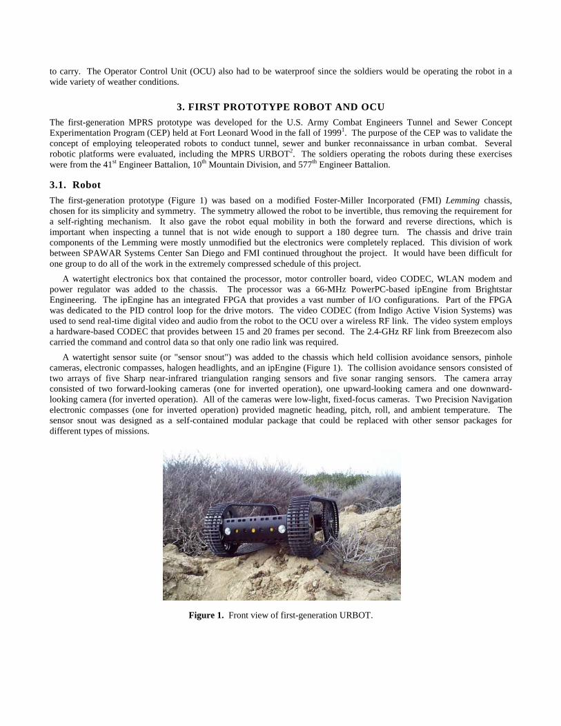
The first-generation prototype (Figure 1) was based on a modified Foster-Miller Incorporated (FMI) Lemming chassis,chosen for its simplicity and symmetry. The symmetry allowed the robot to be invertible, thus removing the requirement fora self-righting mechanism. It also gave the robot equal mobility in both the forward and reverse directions, which isimportant when inspecting a tunnel that is not wide enough to support a 180 degree turn. The chassis and drive traincomponents of the Lemming were mostly unmodified but the electronics were completely replaced. This division of workbetween SPAWAR Systems Center San Diego and FMI continued throughout the project. It would have been difficult forone group to do all of the work in the extremely compressed schedule of this project.
A watertight electronics box that contained the processor, motor controller board, video CODEC, WLAN modem andpower regulator was added to the chassis. The processor was a 66-MHz PowerPC-based ipEngine from BrightstarEngineering. The ipEngine has an integrated FPGA that provides a vast number of I/O configurations. Part of the FPGAwas dedicated to the PID control loop for the drive motors. The video CODEC (from Indigo Active Vision Systems) wasused to send real-time digital video and audio from the robot to the OCU over a wireless RF link. The video system employsa hardware-based CODEC that provides between 15 and 20 frames per second. The 2.4-GHz RF link from Breezecom alsocarried the command and control data so that only one radio link was required.
A watertight sensor suite (or "sensor snout") was added to the chassis which held collision avoidance sensors, pinholecameras, electronic compasses, halogen headlights, and an ipEngine (Figure 1). The collision avoidance sensors consisted oftwo arrays of five Sharp near-infrared triangulation ranging sensors and five sonar ranging sensors. The camera arrayconsisted of two forward-looking cameras (one for inverted operation), one upward-looking camera and one downward-looking camera (for inverted operation). All of the cameras were low-light, fixed-focus cameras. Two Precision Navigationelectronic compasses (one for inverted operation) provided magnetic heading, pitch, roll, and ambient temperature. Thesensor snout was designed as a self-contained modular package that could be replaced with other sensor packages fordifferent types of missions.
Figure 1. Front view of first-generation URBOT.

3.2. OCU
The first-generation OCU consisted of three subassemblies: the electronics box, battery box, and control pendant. Theelectronics box contained a Breezecom WLAN modem, video CODEC, ipEngine, small Ethernet hub, and a video overlayboard. The control pendant used capacitive touch-sensor technology (from Quantum Research) for user input, andincorporated an integrated 2.5-inch LCD video monitor (Figure 2). The capacitive touch sensor allowed the control pendantto be completely waterproof since no mechanical buttons were needed. It also made it possible to operate the system whilewearing the bulky gloves of a chemical suit. The LCD screen displayed the live video feed from the robot as well as vehiclestatus information (heading, speed, pitch, roll, and camera view) overlaid at the top of the screen.
Figure 2. Original control pendant with capacitive touch pad.
4. FINAL MPRS URBOT CONFIGURATION
The CEP at Fort Leonard Wood provided invaluable feedback from the user community. Based on that feedback as well asissues discovered by the design team, a second-generation MPRS robot was developed and subsequently deployed at FortDrum, NY and Fort Polk, LA during the Joint Combined Forces (JCF) Advanced Warrior Experiment (AWE) in Septemberof 2000.
4.1. Robot
The platform chassis was upgraded from the Lemming to a variant of the six-wheel Foster-Miller Tactical Adjustable Robot(TAR), with a fixed length of 33 inches (i.e., no longer adjustable) to save weight (Figure 3). The addition of a slightly over-sized center wheel creates a high-center pivot point that allows the robot to turn much more efficiently. This not only reducesthe power required to pivot on a high-friction surface, but it also allows much more precise control, which is crucial when therobot is used as the pan axis of the inspection camera.
Figure 3. The second-generation URBOT.
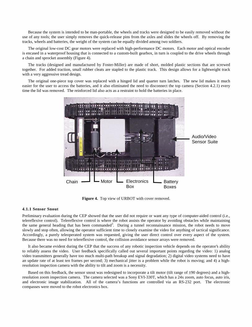
Because the system is intended to be man-portable, the wheels and tracks were designed to be easily removed without theuse of any tools; the user simply removes the quick-release pins from the axles and slides the wheels off. By removing thetracks, wheels and batteries, the weight of the system can be equally divided among two soldiers.
The original low-cost DC gear motors were replaced with high-performance DC motors. Each motor and optical encoderis encased in a waterproof housing that is connected to a custom-built gearbox, in turn is coupled to the drive wheels througha chain and sprocket assembly (Figure 4).
The tracks (designed and manufactured by Foster-Miller) are made of short, molded plastic sections that are screwedtogether. For added traction, small rubber cleats are stapled to the plastic track. This design allows for a lightweight trackwith a very aggressive tread design.
The original one-piece top cover was replaced with a hinged lid and quarter turn latches. The new lid makes it mucheasier for the user to access the batteries, and it also eliminated the need to disconnect the top camera (Section 4.2.1) everytime the lid was removed. The reinforced lid also acts as a restraint to hold the batteries in place.
Figure 4. Top view of URBOT with cover removed.
4.1.1 Sensor Snout
Preliminary evaluation during the CEP showed that the user did not require or want any type of computer-aided control (i.e.,telereflexive control). Telereflexive control is where the robot assists the operator by avoiding obstacles while maintainingthe same general heading that has been commanded3. During a tunnel reconnaissance mission, the robot needs to moveslowly and stop often, allowing the operator sufficient time to closely examine the video for anything of tactical significance.Accordingly, a purely teleoperated system was requested, giving the user direct control over every aspect of the system.Because there was no need for telereflexive control, the collision avoidance sensor arrays were removed.
It also became evident during the CEP that the success of any robotic inspection vehicle depends on the operator’s abilityto reliably assess the video. User feedback specifically called out several important points regarding the video: 1) analogvideo transmitters generally have too much multi-path breakup and signal degradation; 2) digital video systems need to havean update rate of at least ten frames per second; 3) mechanical jitter is a problem while the robot is moving; and 4) a high-resolution inspection camera with the ability to tilt and zoom is a necessity.
Based on this feedback, the sensor snout was redesigned to incorporate a tilt motor (tilt range of ±90 degrees) and a high-resolution zoom inspection camera. The camera selected was a Sony EVI-330T, which has a 24x zoom, auto focus, auto iris,and electronic image stabilization. All of the camera’s functions are controlled via an RS-232 port. The electroniccompasses were moved to the robot electronics box.
Chain Motor BatteryBoxes
Audio/VideoSensor Suite
ElectronicsBox
The new snout was designed to be a modular payload that could be replaced with other payload packages in an almostplug-and-play manner. This is possible because each payload package contains an ipEngine that is networked with theipEngine in the electronics box via Ethernet. The robot uses dynamic registration (see Software section) to recognize whattype of payload is attached and what its corresponding functions are.
4.2.1. Cameras
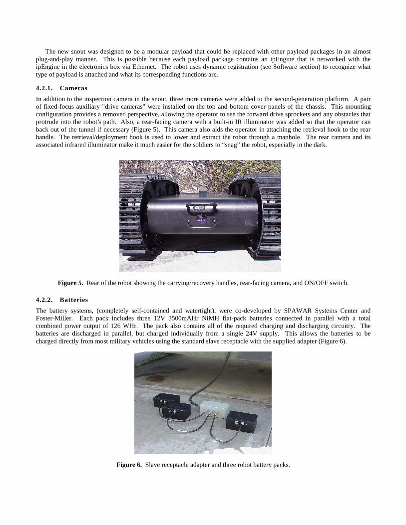
In addition to the inspection camera in the snout, three more cameras were added to the second-generation platform. A pairof fixed-focus auxiliary "drive cameras" were installed on the top and bottom cover panels of the chassis. This mountingconfiguration provides a removed perspective, allowing the operator to see the forward drive sprockets and any obstacles thatprotrude into the robot’s path. Also, a rear-facing camera with a built-in IR illuminator was added so that the operator canback out of the tunnel if necessary (Figure 5). This camera also aids the operator in attaching the retrieval hook to the rearhandle. The retrieval/deployment hook is used to lower and extract the robot through a manhole. The rear camera and itsassociated infrared illuminator make it much easier for the soldiers to “snag” the robot, especially in the dark.
Figure 5. Rear of the robot showing the carrying/recovery handles, rear-facing camera, and ON/OFF switch.
4.2.2. Batteries
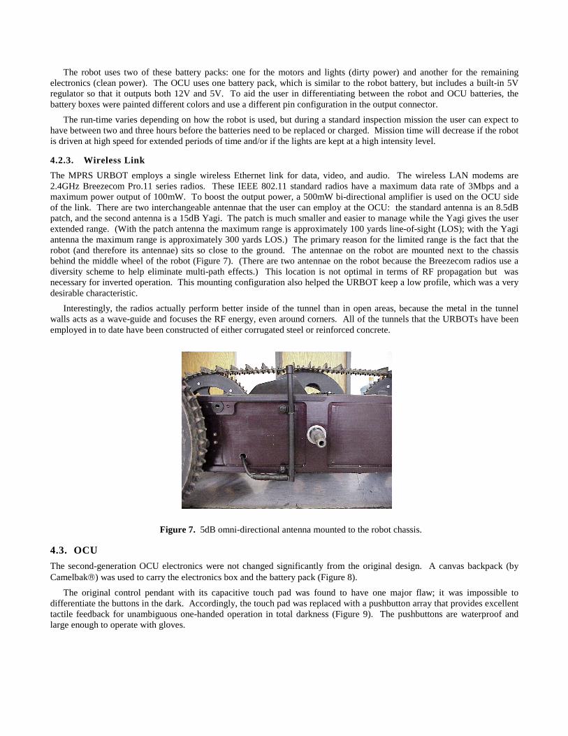
The battery systems, (completely self-contained and watertight), were co-developed by SPAWAR Systems Center andFoster-Miller. Each pack includes three 12V 3500mAHr NiMH flat-pack batteries connected in parallel with a totalcombined power output of 126 WHr. The pack also contains all of the required charging and discharging circuitry. Thebatteries are discharged in parallel, but charged individually from a single 24V supply. This allows the batteries to becharged directly from most military vehicles using the standard slave receptacle with the supplied adapter (Figure 6).
Figure 6. Slave receptacle adapter and three robot battery packs.
The robot uses two of these battery packs: one for the motors and lights (dirty power) and another for the remainingelectronics (clean power). The OCU uses one battery pack, which is similar to the robot battery, but includes a built-in 5Vregulator so that it outputs both 12V and 5V. To aid the user in differentiating between the robot and OCU batteries, thebattery boxes were painted different colors and use a different pin configuration in the output connector.
The run-time varies depending on how the robot is used, but during a standard inspection mission the user can expect tohave between two and three hours before the batteries need to be replaced or charged. Mission time will decrease if the robotis driven at high speed for extended periods of time and/or if the lights are kept at a high intensity level.
4.2.3. Wireless Link
The MPRS URBOT employs a single wireless Ethernet link for data, video, and audio. The wireless LAN modems are2.4GHz Breezecom Pro.11 series radios. These IEEE 802.11 standard radios have a maximum data rate of 3Mbps and amaximum power output of 100mW. To boost the output power, a 500mW bi-directional amplifier is used on the OCU sideof the link. There are two interchangeable antennae that the user can employ at the OCU: the standard antenna is an 8.5dBpatch, and the second antenna is a 15dB Yagi. The patch is much smaller and easier to manage while the Yagi gives the userextended range. (With the patch antenna the maximum range is approximately 100 yards line-of-sight (LOS); with the Yagiantenna the maximum range is approximately 300 yards LOS.) The primary reason for the limited range is the fact that therobot (and therefore its antennae) sits so close to the ground. The antennae on the robot are mounted next to the chassisbehind the middle wheel of the robot (Figure 7). (There are two antennae on the robot because the Breezecom radios use adiversity scheme to help eliminate multi-path effects.) This location is not optimal in terms of RF propagation but wasnecessary for inverted operation. This mounting configuration also helped the URBOT keep a low profile, which was a verydesirable characteristic.
Interestingly, the radios actually perform better inside of the tunnel than in open areas, because the metal in the tunnelwalls acts as a wave-guide and focuses the RF energy, even around corners. All of the tunnels that the URBOTs have beenemployed in to date have been constructed of either corrugated steel or reinforced concrete.
Figure 7. 5dB omni-directional antenna mounted to the robot chassis.
4.3. OCU
The second-generation OCU electronics were not changed significantly from the original design. A canvas backpack (byCamelbak) was used to carry the electronics box and the battery pack (Figure 8).
The original control pendant with its capacitive touch pad was found to have one major flaw; it was impossible todifferentiate the buttons in the dark. Accordingly, the touch pad was replaced with a pushbutton array that provides excellenttactile feedback for unambiguous one-handed operation in total darkness (Figure 9). The pushbuttons are waterproof andlarge enough to operate with gloves.
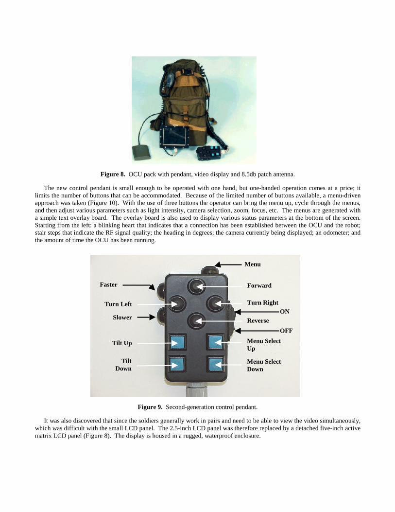
Figure 8. OCU pack with pendant, video display and 8.5db patch antenna.
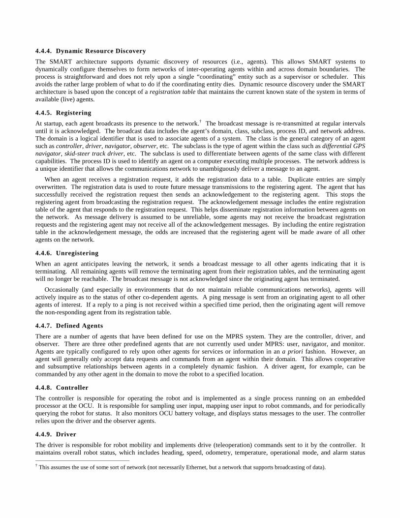
The new control pendant is small enough to be operated with one hand, but one-handed operation comes at a price; itlimits the number of buttons that can be accommodated. Because of the limited number of buttons available, a menu-drivenapproach was taken (Figure 10). With the use of three buttons the operator can bring the menu up, cycle through the menus,and then adjust various parameters such as light intensity, camera selection, zoom, focus, etc. The menus are generated witha simple text overlay board. The overlay board is also used to display various status parameters at the bottom of the screen.Starting from the left: a blinking heart that indicates that a connection has been established between the OCU and the robot;stair steps that indicate the RF signal quality; the heading in degrees; the camera currently being displayed; an odometer; andthe amount of time the OCU has been running.
Figure 9. Second-generation control pendant.
It was also discovered that since the soldiers generally work in pairs and need to be able to view the video simultaneously,which was difficult with the small LCD panel. The 2.5-inch LCD panel was therefore replaced by a detached five-inch activematrix LCD panel (Figure 8). The display is housed in a rugged, waterproof enclosure.
Faster
Slower
Menu
Tilt Up
TiltDown
Turn Left Turn Right
Forward
Reverse
Menu SelectUp
Menu SelectDown
ON
OFF
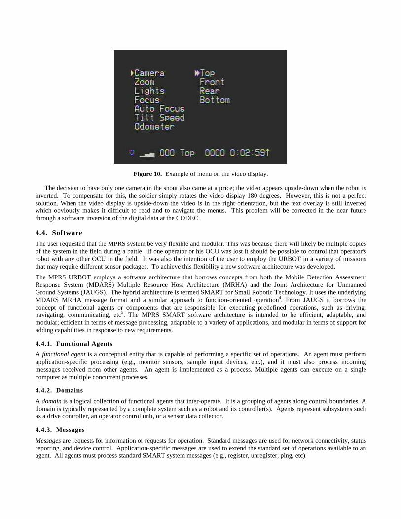
Figure 10. Example of menu on the video display.
The decision to have only one camera in the snout also came at a price; the video appears upside-down when the robot isinverted. To compensate for this, the soldier simply rotates the video display 180 degrees. However, this is not a perfectsolution. When the video display is upside-down the video is in the right orientation, but the text overlay is still invertedwhich obviously makes it difficult to read and to navigate the menus. This problem will be corrected in the near futurethrough a software inversion of the digital data at the CODEC.
4.4. Software
The user requested that the MPRS system be very flexible and modular. This was because there will likely be multiple copiesof the system in the field during a battle. If one operator or his OCU was lost it should be possible to control that operator’srobot with any other OCU in the field. It was also the intention of the user to employ the URBOT in a variety of missionsthat may require different sensor packages. To achieve this flexibility a new software architecture was developed.
The MPRS URBOT employs a software architecture that borrows concepts from both the Mobile Detection AssessmentResponse System (MDARS) Multiple Resource Host Architecture (MRHA) and the Joint Architecture for UnmannedGround Systems (JAUGS). The hybrid architecture is termed SMART for Small Robotic Technology. It uses the underlyingMDARS MRHA message format and a similar approach to function-oriented operation4. From JAUGS it borrows theconcept of functional agents or components that are responsible for executing predefined operations, such as driving,navigating, communicating, etc5. The MPRS SMART software architecture is intended to be efficient, adaptable, andmodular; efficient in terms of message processing, adaptable to a variety of applications, and modular in terms of support foradding capabilities in response to new requirements.
4.4.1. Functional Agents
A functional agent is a conceptual entity that is capable of performing a specific set of operations. An agent must performapplication-specific processing (e.g., monitor sensors, sample input devices, etc.), and it must also process incomingmessages received from other agents. An agent is implemented as a process. Multiple agents can execute on a singlecomputer as multiple concurrent processes.
4.4.2. Domains
A domain is a logical collection of functional agents that inter-operate. It is a grouping of agents along control boundaries. Adomain is typically represented by a complete system such as a robot and its controller(s). Agents represent subsystems suchas a drive controller, an operator control unit, or a sensor data collector.
4.4.3. Messages
Messages are requests for information or requests for operation. Standard messages are used for network connectivity, statusreporting, and device control. Application-specific messages are used to extend the standard set of operations available to anagent. All agents must process standard SMART system messages (e.g., register, unregister, ping, etc).
4.4.4. Dynamic Resource Discovery
The SMART architecture supports dynamic discovery of resources (i.e., agents). This allows SMART systems todynamically configure themselves to form networks of inter-operating agents within and across domain boundaries. Theprocess is straightforward and does not rely upon a single “coordinating” entity such as a supervisor or scheduler. Thisavoids the rather large problem of what to do if the coordinating entity dies. Dynamic resource discovery under the SMARTarchitecture is based upon the concept of a registration table that maintains the current known state of the system in terms ofavailable (live) agents.
4.4.5. Registering
At startup, each agent broadcasts its presence to the network.† The broadcast message is re-transmitted at regular intervalsuntil it is acknowledged. The broadcast data includes the agent’s domain, class, subclass, process ID, and network address.The domain is a logical identifier that is used to associate agents of a system. The class is the general category of an agentsuch as controller, driver, navigator, observer, etc. The subclass is the type of agent within the class such as differential GPSnavigator, skid-steer track driver, etc. The subclass is used to differentiate between agents of the same class with differentcapabilities. The process ID is used to identify an agent on a computer executing multiple processes. The network address isa unique identifier that allows the communications network to unambiguously deliver a message to an agent.
When an agent receives a registration request, it adds the registration data to a table. Duplicate entries are simplyoverwritten. The registration data is used to route future message transmissions to the registering agent. The agent that hassuccessfully received the registration request then sends an acknowledgement to the registering agent. This stops theregistering agent from broadcasting the registration request. The acknowledgement message includes the entire registrationtable of the agent that responds to the registration request. This helps disseminate registration information between agents onthe network. As message delivery is assumed to be unreliable, some agents may not receive the broadcast registrationrequests and the registering agent may not receive all of the acknowledgement messages. By including the entire registrationtable in the acknowledgement message, the odds are increased that the registering agent will be made aware of all otheragents on the network.
4.4.6. Unregistering
When an agent anticipates leaving the network, it sends a broadcast message to all other agents indicating that it isterminating. All remaining agents will remove the terminating agent from their registration tables, and the terminating agentwill no longer be reachable. The broadcast message is not acknowledged since the originating agent has terminated.
Occasionally (and especially in environments that do not maintain reliable communications networks), agents willactively inquire as to the status of other co-dependent agents. A ping message is sent from an originating agent to all otheragents of interest. If a reply to a ping is not received within a specified time period, then the originating agent will removethe non-responding agent from its registration table.
4.4.7. Defined Agents
There are a number of agents that have been defined for use on the MPRS system. They are the controller, driver, andobserver. There are three other predefined agents that are not currently used under MPRS: user, navigator, and monitor.Agents are typically configured to rely upon other agents for services or information in an a priori fashion. However, anagent will generally only accept data requests and commands from an agent within their domain. This allows cooperativeand subsumptive relationships between agents in a completely dynamic fashion. A driver agent, for example, can becommanded by any other agent in the domain to move the robot to a specified location.
4.4.8. Controller
The controller is responsible for operating the robot and is implemented as a single process running on an embeddedprocessor at the OCU. It is responsible for sampling user input, mapping user input to robot commands, and for periodicallyquerying the robot for status. It also monitors OCU battery voltage, and displays status messages to the user. The controllerrelies upon the driver and the observer agents.
4.4.9. Driver
The driver is responsible for robot mobility and implements drive (teleoperation) commands sent to it by the controller. Itmaintains overall robot status, which includes heading, speed, odometry, temperature, operational mode, and alarm status † This assumes the use of some sort of network (not necessarily Ethernet, but a network that supports broadcasting of data).
(low battery, tilt limit, excessive temperature). It is intended to implement a variety of mobility behaviors includingteleoperation, reflexive teleoperation (sensor-aided teleoperation), and supervised autonomous operation (directed GPSnavigation). On the second-generation URBOT the only behavior implemented is teleoperation. The driver relies upon theobserver to supply environmental and navigational information such as temperature, heading, and pitch/roll.
4.4.10. Observer
The observer is responsible for robot sensory input. On the first-generation URBOT it controlled the array of ultrasonicranging sensors, IR ranging sensors, temperature and heading sensors, and pitch/roll sensors. The sensor data is stored by theobserver for transmission to other agents upon request. On the second-generation URBOT the observer is responsible forpositioning the tilt housing and controlling the video camera. The observer does not rely upon any other agent (i.e., it iscompletely independent).
5. LESSONS LEARNED AT THE ADVANCED WARRIOR EXPERIMENT
The second-generation MPRS URBOTs were used in several Army exercises at Fort Drum, NY prior to the AWE as well asat the AWE. At each of these exercises, new issues came to light with respect to how the robot performed in variousconditions and how the users perceived the URBOT’s role.
5.1. Mechanical
As a whole, the mechanical design worked very well, and proved to be rugged and reliable even in the hands of enlistedsoldiers. The system even endured an accidental seven-foot drop test, which occurred because of a poorly designeddeployment rope. The deployment rope was configured to allow the soldiers to lower the robot into a sewer system via amanhole. The deployment system consisted of two ropes, one to carry the weight of the robot and a second to release thepanic latch once the robot was safely on the tunnel floor. The problem with this approach was that the release rope had to becarefully tended so that it did not become tight and release the robot prematurely in midair. In the end, this system was muchtoo complex. During training the release rope was inadvertently tensioned and the robot dropped seven feet, snout-first, ontoa concrete floor. The positive side of this failure was that it tested the robot in a way that would never have been donedeliberately. The robot was extracted from the tunnel, powered up, and ran fine. There was almost no visual damage, and oncloser inspection the only damage found was a slightly bent snout pivot shaft.
Another minor mechanical problem was the rigidity of the hinged lid. It was discovered that when the robot climbs up avertical obstacle such as a wall and flips over backwards, the impact of the batteries deforms the lid slightly. This is not acatastrophic failure in that the lid still holds the batteries in place. However, if this were to occur numerous times the lid mayeventually fail.
The only significant mechanical problem with the system is the track. Foster-Miller designed the track for the Lemmingsystem, which was a much lighter, less powerful vehicle. The larger, heavier URBOT created stresses on the track thatroutinely pulled sections apart and ripped the thin plastic webbing. Foster-Miller currently has an updated track design that isa continuous belt made of a much stronger material. Unfortunately, there was insufficient time to upgrade the URBOTsystem to this new design before the AWE.
Overall the soldiers had very few complaints with respect to the mechanical systems. They did state that the system wastoo heavy to pack over long distances. The complete system including a spare set of batteries weighs approximately 100pounds. At 50 pounds per person this is 10 pounds over the design goal. This is almost entirely due to the fact that thesoldiers have to carry spare batteries into the field. (The spare batteries are needed because there is no way for the soldiers tocharge the batteries during an exercise.)
It was also discovered that the URBOT was not fast enough to keep up with the momentum of an attack. During an attackon a city, momentum is everything; if someone or something cannot keep up it gets left behind. The original designrequirement called for a minimum speed of 3 feet per second. The URBOT’s top speed is approximately 2.5 feet per second.This was short of the design requirement, and even the original requirement is not nearly as fast as the soldiers would like.The new requirement is for a system that is closer to 10 feet per second. Foster-Miller already has a new motor design (usingbrushless DC motors) that will increase the maximum speed of the URBOT to approximately 6 feet per second.
5.2. Electrical
The electronic systems also performed very well. It was stated on many occasions that the video system was the best that hasbeen employed on a portable robot to date. The only major drawback to the digital video system is the high bandwidth
requirement and hence the requirement for a WLAN modem and the high frequencies employed by these radios. Because ofthe low-power and high-frequency characteristics of these radios, the communications range is generally limited to LOS.These restrictions can be overcome in some instances by the use of repeaters and high-gain antennas.
The primary problem with the electrical system was the water-tight connectors: there were repeated failures of theconnectors throughout the system. This can be mostly attributed to the fact that engineers built many of the cables rather thantrained technicians, and in part to the complicated nature of the watertight connectors that were used. Each connector ismade of four to five pieces that must be custom ordered to fit the cable. On a project with such a compressed schedule it wasdifficult to maintain the required tolerances.
Another problem that came to light during the Fort Drum exercises was that there is no power gauge on the battery boxesto indicate the level of charge left in the battery pack. Many of the problems reported by the soldiers were determined to be aresult of insufficiently charged batteries. For the AWE, a self-contained battery tester was fabricated so that the soldierscould verify that the batteries were fully charged prior to the mission.
As anticipated, the summer heat in Louisiana was a minor problem during the AWE. At times the ambient temperaturereached 115 degrees Fahrenheit and the heat index was over 130 degrees. When the system was run for an extended periodin direct sunlight some of the integrated circuits failed. The resolution to this problem was to simply turn the system off andlet it cool down for about 30 minutes. This problem was not a surprise since all of the electronics in the system arecommercial grade and not rated for such extreme heat conditions.
5.3. Training
The biggest problem encountered during the entire twelve month project did not concern the mechanical or electricalsystems, but instead with the "trained" operators. In order for any robotic system (even one as simple as the URBOT) to besuccessful, the operator of that system must be intimately familiar with how the system works and what its strengths andweakness are. The only way someone can obtain this kind of familiarity is to train with the system repeatedly.Unfortunately, the Army was not able to permanently dedicate personnel to the URBOT initiative, with the result that atevery exercise the URBOT operators were soldiers with only a brief introduction to the system. In addition, inadequatelytrained operators have little or no troubleshooting ability. This meant that when a minor problem arose with the robot, thesoldiers just quit using it instead of trying to work through the problem.
5.4. User Wish List
Every time the design team met with the soldiers for either training or an actual exercise there was an enthusiastic stream ofsuggestions on how the URBOT could be improved. Some of the most frequent and practical suggestions are listed below.
The primary concern to the soldiers was the fact that the URBOT introduced new batteries into what is an alreadyimmense variety of batteries that have to be carried into the field. It was repeatedly requested that the URBOT batteries wereat least interchangeable (same battery for OCU and robot). Even higher on the wish list was that that URBOT use a standardbattery that the Army already carries. This option was investigated but it was found that the Army-issue batteries hadnowhere near the energy density that was required for the desired run-time.
Another suggestion that came out of the Fort Drum exercises was that the URBOT have night vision capability. Thesoldiers not only wanted to use the robot for tunnel inspection but also for building inspection and surveillance. The onlyway the URBOT can currently be used at night is with halogen headlights, which immediately gives its position away. Theaddition of a small FLIR camera is being investigated.
Probably the most common request from the enlisted soldiers was for a more lethal robot. They want a robot that can beused not only for reconnaissance, but also to attack the enemy and defend a position. Technically, this would not be adifficult addition (aside from the added weight). The first step to such a system is the addition of non-lethal weapons, whichis being pursued by Foster-Miller.
REFERENCES
1. Laird, R.T., Bruch, M.H., "Issues in Vehicle Teleoperation for Tunnel and Sewer Reconnaissance," IEEE Conferenceon Robotics and Automation, San Francisco, CA, April 2000.
2. Pulaski, G., "Engineer Test Report for Tunnel and Sewer CEP, Draft Version", Battle Lab and Test and EvaluationCoordination Office, Ft. Leonard Wood, MO, March 2000.
3. Laird, R.T., Everett, H.R., "Reflexive Teleoperated Control," Association For Unmanned Vehicle Systems, 17th AnnualTechnical Symposium and Exhibition (AUVS ’90), Dayton, OH, pp. 280-292, July-August, 1990.
4. Everett, H.R., Laird, R.T., Gilbreath, G., Heath-Pastore, T.A., Inderieden, R.S, Grant, K., Jaffee, D.M., "MultipleResource Host Architecture for the Mobile Detection Assessment Response System," Technical Document 3026, Spaceand Naval Warfare Systems Center, San Diego, CA, August 1998.
5. Unmanned Ground Vehicles/Systems Joint Program Office, "Joint Architecture for Unmanned Ground Systems,"Volume II, Redstone Arsenal, AL, September 2000.