Challenge 4 - awim.org · Welcome to SAE’s “A World in Motion” adventures in Electricity and...
40
Challenge 4 Electricity and Electronics Middle School 060528 MidCrv
Transcript of Challenge 4 - awim.org · Welcome to SAE’s “A World in Motion” adventures in Electricity and...

Challenge 4Electricity and Electronics
Middle School060528 MidCrv

Lesson Plans are not included in this document.
Check out the sample lesson plan located in the curriculum
resources.

CHALLENGE 4 MIDDLE SCHOOL LEVEL

�
SAE INTERNATIONAL
SAE is a non-profit educational and scientific organization dedicated to advancing mobility technology to better serve humanity. Over 89,000 engineers and scientists, who are SAE members, develop technical information on all forms of self-propelled vehicles including automobiles, trucks and buses, off-highway equipment, aircraft, aerospace vehicles, marine, rail, and transit systems. SAE disseminates this information through its meetings, books, technical papers, magazines, standards, reports, professional development programs, and electronic databases
SAE FOUNDATION
Since 1986, the SAE Foundation has not only supported, but also nurtured students’ enthusiasm for science and technology education. Through award winning K-12 Educational Programs, dynamic Collegiate Design Series competitions, and numerous Scholarship and Award Programs, the SAE Foundation builds bridges between corporations and classrooms by giving engineers, school teachers, and students the opportunity to work together and learn from each other.
To lend your support to these efforts, please contact the SAE Foundation at (724) 772-4841.
Copyright © 2005 by SAE International. All rights reserved. Permission to reproduce the teacher manual and student hand-outs is hereby granted by
SAE International to teachers for classroom use.
Revision of original edition published in 2003.

�
Acknowledgements
SAE International, and the SAE Foundation, Warrendale, Pennsylvania.Ray Morris, SAE International, Executive Vice President & COORobert H. Chalker, SAE Sales and Marketing, DirectorKathleen M. O’Connor, SAE K-12 Education Programs, ManagerMatthew M. Miller, SAE K-12 Education Programs, Program DeveloperJames Cook, AWIM Senior AdvisorVeronica Meury, SAE Foundation, Director
Written and Developed by EOA Scientific Systems, Inc.
Revised byLorton Trent, Purpose Driven Engineering, TXDr. Charles Lovas, I.D.E.A.S.
Advisors, Consultants, and ReviewersMary Beth Ament, Tom Breletic, Sue Cardillo, Sue Casker, Melissa Crownover, Edward J. Debler, Mohamed El-Hussieny, Bob Everett, Becky Fadik, Ken Francis Steven A. Gadzinski, Rebecca George, Mary-Jo Germain, Darlene Geweth, Jerry D. Glidewell, Debra Grant, Anand K. Iyer, Walter E. Jones, Karl Klimek, Linda Lenar, Barbara Logan, Cuneyt Oge, Robert H. Poel, Neil Schilke, Ro Schilke, Joann Schneider, James Solski, Gregory A. Stiles, Myron Trenne, Kevin Webber, Kathy Yaeger
A World In Motion® program development and expansion has been made possible through the generous contributions of The Door Foundation and major support from:Caterpillar FoundationDaimler Chrysler Corporation FundEDSFord Motor CompanyGeneral Motors CorporationHonda North America, Inc.Toyota Motor Corporation
And the generous support of SAE members throughout North America.

�
Welcome to SAE’s “A World in Motion” adventures in Electricity and Electronics!
SAE International is a nonprofit scientific organization dedicated to the advancement of mobility technology in order to better serve humanity. A global society of approximately 80,000 members, SAE is the leading professional organization for engineers and scientists involved with land, sea, air, and space mobility. Its members come from all branches of engineering, science, and technology. SAE creates and distributes information through meetings, books, technical papers, magazines, standards, reports, continuing education programs, and electronic databases.
You will be learning about Electricity and Electronics constructing your own working models of different demonstrations in the following investigations.
You will be dividing into groups, with each group member having a different role. Decide which member in your group will fill which role; use the Engineering Design Team sheet as a guideline for what each group member’s assignment will be.
Do not write on the handout sheets in the manual. Your teacher will let you know if there will be individual copies of handouts made, or the artist in your group can draw any of the sheets on paper.
Enjoy your adventures.
Have fun!
Introduction
Welcome to “A World In Motion®” Students’ Guide
Experiments in Electricity and Electronics

�
Table of Contentsof Student Experiments
Level C Experiments: CircuitsGetting Started ..................................................................................7
C1 Series and ParallelCircuits – 1 ....................................................9C2 Series and Parallel Circuits – 2 ................................................. 18C3 Series and Parallel Circuits - 3 .................................................. 28C4 Series and Parallel Circuits - 4 .................................................. 37C5 Series and Parallel Circuits - 5 .................................................. 47
Level D Experiments: Magnetism and Introduction to ElectronicsGetting Started ................................................................................ 56
D1 Solenoid Switch ..................................................................... 58D2 Galvanometer ........................................................................ 63D3 Electric Motor ........................................................................ 68D4 Flashing Lights ...................................................................... 74D5 Transistor LED Driver .............................................................. 79
Background Information: Student Handouts
Using Ohm’s Law with Series and Parallel Circuits ............................ 82The Breadboard ........................................................................... 92Engineering Design Team .............................................................. 94The Multimeter ........................................................................... 95The Group Power Supply ..............................................................100Observations and Conclusions .......................................................102Electromagnetism and Introduction to Electronics ..........................103Alternating Current (AC) .............................................................109

�
Safety PrecautionsRead this section before performing any experimentsCare of the batteries and the power supplyShorted batteries can and will get very hot, which can result in burns and various other hazards.
1. “Shorting” batteries means connecting the “+” terminal to the “-” terminal with wires or any other metal object. Batteries may also get hot when under heavy load, or in other words, when a large current is being drained from the battery. This heavy load can happen when a low resistance device such as a light bulb or motor is connected.
2. The variable voltage battery supply will be made from several batteries joined together. It will be tempting for the students to connect the batteries with wire or alligator clips. Prevent this practice and store the batteries separately.
3. In electromagnetic experiments such as Level D 1, 2, and 3 (solenoid switch, galvanometer, and electric motor), leave the experiment connected for only a short period of time since they are low resistance and will get hot quickly.
4. As with any battery, do not dispose of them in fire—they may explode. The electrolyte is corrosive and can cause damage to the eyes and skin. Protect the batteries against condensation if they are stored in a freezer to extend their life; thaw before using.
Small Components and Pointed WiresThe small components and sharp pointed wires present a hazard and can cause injury if used improperly.
TAKE CARE!!
Remember, YOU the Teacher are responsible for what happens in your classroom. Neither the SAE Foundation, EOA Scientific, nor Purpose Driven Engineering have liability for any injuries that may occur from the use of this equipment or the performance of these experiments. Review the equipment, experiments, and procedures to make sure you are comfortable with that responsibility.

�
Getting Started-Level CSuggested Grade Levels – � - 8.
GoalsThese experiments demonstrate series and parallel circuits and their effects using simple electronic components, a breadboard, and a power supply.
Instructor PreparationThe instructor and the students should first review all background information provided in an introductory session. If time permits, the instructor should complete one or two experiments independently before starting the experiments with the class.
The levels are structured progressively in that each contains information required to advance to the next level. Starting at a level without the requisite background information is not recommended.
Some teachers may not be familiar with certain technical concepts but are strongly urged to lead activities, which take this factor into consideration. The teacher has the option of being a “guide on the side” in conjunction with the SAE facilitator, who can offer more technical expertise.
Background Information RequiredStudent Handouts Page # CopiesNew:
Using Ohm’s Law with Series and Parallel Circuits.......... 82 ......................... 1 per student The Breadboard ................................... 92 ......................... 1 per group
Engineering Design Team ...................... 94 ......................... 1 per group The Multimeter ................................... 95 ......................... 1 per group Group Power Supply ............................. 100 ....................... 1 per group

8�
Student Handout – Using Ohm’s Law
Using Ohm’s Law with Series and Parallel CircuitsWhat’s an Ohm, anyway?
Ohm’s law is named after a scientist, Georg Ohm (1789-1854).
An ohm is a number that results from measuring the voltage (or pressure) in a circuit that causes electricity to flow, and the amount of electricity that actually flows (called the current, and measured in amperes (amps)).
In other words, it measures the resistance of the flow of electricity from a battery or through the electrical outlets in your home
V (voltage) = I (current) x R (resistance)I (current) = V (voltage) ÷ R (resistance)R (resistance) = V (voltage) ÷ R (current)
V is measured in volts (V).I is measured in amperes
(amps – A)).R is measured in ohms (Ω).For example:
If V = 10 volts, and a resistor R = 10 ohms, what is I (current)?I = V/R
= 10/10 = 1 amp
V
I R
V=
I Rx
V
I= R
V
I R=
Student Handout – Using Ohm’s Law
Example Problem:A 9-V battery supplies power to a cordless curling iron with a resistance of 18 Ω. How much current is flowing through the curling iron?
Solution:Sketch the circuit.
Solve the problem with Ohm’s law resistors:1.) Since V (Voltage) and R (Resistance) are known, solve for I (Current)
by dividing both sides of the equation by R.
2.) The Rs on the right-hand side of the equation cancel.
3.) I is then left in terms of V and R.
4.) Substitute in the values for V (Voltage) and R (Resistance).
5.) Solve for I (Current).
Hint!By remembering the triangle shape
and where the letters are, you can calculate using Ohm’s Law:

8�
Problem #1
A 110-V wall outlet supplies power to a strobe light with a resistance of 2200 Ω. How much current is flowing through the strobe light?
Choose your answer below1. 25.0 A2. 0.50 A3. 1.00 A4. 0.05 A
Problem #�
A CD player with a resistance of 40 Ω has a current of 0.1 A flowing through it. Sketch the circuit diagram and calculate how many volts supply the CD player.
Choose your answer below1. .0025 V2. 4.00 V3. 10.0 V4. 400.0 V
Kirchoff’s law
Kirchoff developed two laws governing electric circuits in which steady current flows. (1.) The algebraic sum of the voltage gains or drops in a closed circuit is zero and (2.) the sum of the currents entering a point equals the currents leaving that point.
The second law means that since electric charge is conserved (all that goes in comes out), whatever current (electron flow) goes into a point will come out of that point.
The first law means that since energy is conserved, the total inflow of energy into a circuit must equal the total outflow of energy plus the gain or loss of energy inside the circuit. Therefore, the algebraic sum of the electrical potential differences around a circuit will add to zero.
This law may be seen in the above examples.
Student Handout – Using Ohm’s Law
In the example, a 9-V battery is providing 0.5 A to the 18 Ω curling iron. From Kirchoff’s first law, we note that the electron current flow goes in a clockwise direction from the V source around through the load R back to the source V. Since electrons are negatively charged, they are attracted to the source’s positive potential terminal (this statement is always true).
Therefore, as the current leaves the source negative terminal on the way around the circuit to the positive terminal, it comes to the resistance of the curling iron. Again, since current always flows from negative to positive, we can assign a negative sign to the top end of the resistance and a positive sign to the bottom end of the resistance. Going on around the circuit, the current comes back to the source (battery) positive terminal. Taking the convention that the first voltage sign encountered in a closed loop circuit is assigned to the voltage in question, we see that the first sign we encountered is negative, so the value is -9 V. The next first sign we encounter continuing on around to the source is positive and the value is +9 V. And true to Kirchoff’s law, the sum of these is:
-9 + 9 = 0
Now you try—Write down your answers to the following:
If R = 10 and I = 5, solve V.
If V = 50 and R =10, what is I?
Series Circuits
Any resistance between the positive (+) and the negative (-) terminals of a source of electrical power is said to be in “series.” While many branches can be connected to the circuit, the total resistance of the circuit is still really one large series circuit where current flows from the negative to the positive terminals of a battery or power source.
Six light bulbs in a series circuit.Notice that the connections are into the light bulb and then out of the light bulb to the next one and so on, until the last light bulb in the chain connects back to the battery. What would happen if you were to disconnect any wire between the light bulbs? Would the other light bulbs light up?
Student Handout – Using Ohm’s Law
Battery
6 volts DC
- +

8�
How to calculate the resistance of the “six light bulbs in a series” circuit:
Because the resistance between the battery’s terminals in the above drawing is like a chain of resistors, you need to know what the resistance of each one is, then add them all up. To make it easier to calculate, name each light R for resistor, then assign a different number to each one. Assume the light bulbs are all the same, and give the value of a light bulb’s resistance as 1 Ω. You would then calculate as follows:
R1 + R2 + R3 + R4 + R5 + R6 = Rt(Rt (=R total) is the total resistance.)OR:1 + 1 + 1 + 1 + 1 + 1 = 6 ohmsTherefore: Rt = 6 Ω
Since all the resistors are the same value, you can also multiply the resistance value of each resistor (ohms) by the quantity of resistors (light bulbs):
Rt = 1 ohm x 6 light bulbs = 6 ohmsUsing Ohm’s Law with Series and Parallel
CircuitsNow look at Ohm’s law again.To find how much current flows in a circuit, calculate I.
I = V/R (current = voltage divided by resistance)
V = 6 VR = 6 ΩI = 6/6 = 1 A
You now know without having to measure the circuit, that this circuit has 1 A of current flow.
In your home, many of the fuses or circuit breakers actually connect to the electricity from the street. For example, most home circuits for lights and TV are 15 A, or 15 amps (amperes), meaning if something that draws more than 15 A were plugged into the circuit or if there was a problem with the wiring “shorting out,” then the fuse would burn out or the circuit breaker would shut the power off.
Student Handout – Using Ohm’s Law
Short Circuits and Fuses
Short CircuitsA short circuit means that there is a short path between battery terminals - or, there is almost NO RESISTANCE between them.
Fuses and Circuit BreakersA fuse “burns”, or a circuit breaker trips automatically to break a connection. Without protection like this, wires could become so hot that the plastic around them could melt, and the heat could start a fire behind your walls.
That is why you always use the correct fuse or circuit breaker recommended for a circuit.
Open and Closed CircuitsThe opposite of a short circuit is an open circuit. This means that nothing is connected between a battery’s positive and negative terminals, and so it is “open”.
Any circuit that has anything connected to it is a closed circuit.
Now bring in the remaining two Ohm’s law calculations and check them:
V = I x R (voltage = current multiplied by resistance)6 = 1 x 6 Correct.
R = V/I (resistance = voltage divided by current)6 = 6/1 Correct.
Parallel Circuits
Circuits in parallel are actually branches within a main circuit. For example, the electricity going to your home does not connect all the homes on the street in a series circuit. If all the houses were in a series circuit, what would happen if one house was disconnected? What would happen is the same thing that happened to the first Christmas tree lights. If one bulb burned out, all the lights in the tree would go out. So, we developed a different way of doing things—we invented the parallel circuit. This time, to make it easier to see, we will use boxes marked R, representing resistors instead of light bulbs.
This looks a little different than the series circuit, doesn’t it? How do you think you would calculate the resistance in this case?
First, you have to break things down into branch circuits. In the drawing, you can see that there are really three groups of two resistors. They are: R1 and R2, R3 and R4, R5 and R6. The current from the battery will flow through R1 and R2 in separate paths then connect in series to R3 and R4, and to R5 and R6.
Make all your resistors the same value as the light bulbs were, 1 Ω. Because the current now has two paths to flow through, R1 and R2, and they are the same value, the actual resistance is only half of what it was! This is what happens in a parallel circuit. R1 and R2 would have different branch currents flowing through them. Since they are the same value of resistance, the current flowing through them is equal. If they were different values, the current flowing through them would depend on the amount of resistance of each resistor, such as:
Student Handout – Using Ohm’s Law
Battery
6 volts DC
- +
R1
R2
R3
R4
R5
R6

88
If R1 and R2 are equal, then one half of the current flows through each.
How can you use Ohm’s law here? First, calculate the resistance for each of the two resistors aligned in parallel. We call this equivalent resistance because the battery reaction is the same as if there were just one resistor.
R = R1 x R2 / R1 + R2R = 1 x 1 / 1 + 1R = 1/2 Ω
This is the formula for calculating the value of two resistors in a parallel circuit.
Because we know the resistors are equal, we can also use the following:
Forequalvalueresistorsonly:R = R value of one resistor / the number of resistors.R = 1/2
Either way, we now know that each branch of the circuit is 1/2 Ω. Now we add together the resistance values of the branches: R1 and R2, R3 and R4, and R5 and R6: 1/2 + 1/2 + 1/2 = 3/2 = 1.5 ohms Therefore, the total resistance of our circuit is 1.5 Ω.
TryusingOhm’slawnowtocalculatehowmuchcurrentwillflowthroughthiscircuit:
I = V / RI = 6 / 1.5I = 4 A
Our circuit is actually a series-parallel circuit because it uses a series circuit arrangement to connect parallel circuits. You used the same six resistors, but the parallel branch arrangement reduced their resistance from 6 to 1.5 Ω; as a result, the current increased from 1 to 4 A.
Tryusingadifferentvalueofresistorineachpair,suchas:
R1 = 1 Ω, and R2 = 2 ΩR = R1 x R2 / R1 + R2R = 1 x 2 / 1 + 2 R = 2 / 3 or .667 Ω
Student Handout – Using Ohm’s Law
One-third of the current would flow through the 2 Ω resistor and 2/3 through the 1 Ω resistor because the lower the resistance, the more current flow, and because the total current is always equal to the sum of the current flow between the two branch currents.
To understand better we need to look at one more law named after another scientist, Gustav Kirchoff.
Kirchoff’s law states that the sum of the voltage drops in a circuit is equal to the total voltage applied to the circuit.
The voltage drops are like the four batteries in a row in your group power supply. Measuring where each battery connects in series, you see 1.5-, 3.0-, 4.5-, and 6.0-V points. If you measured the voltage at each connection point to a pair of resistors in the series parallel circuit here, you would find the following:
1.) We know that each branch of the circuit is 1/2 Ω and that current flow through the entire circuit is 4 A. V= I x R V= 4 x 1/2 V= 2 V at each pair or branch, or a 2-V drop in voltage.
2.) Now use Kirchoff’s law and add the sum or total of the voltage drops. V total = V1 + V2 + V3 V total = 2 + 2 + 2 V total = 6 V, which is the correct battery voltage.
Howdowecalculatetheamountofcurrentflowingthrougheachresistorinthepairs?
I = V / RI = 2 / .5I = 4
We know 4 A is correct because the current flow is the same throughout the whole series circuit of connected pairs.
But individually:R1 = 1 ΩV = 2 VI = V / RI = 2 / 1= 2 A
As R1 and R2 are the same value, then I totals (2 + 2) 4 A again!
Student Handout – Using Ohm’s Law
R1
R2
R1
R2
R1
R2

8�
If R1 and R2 are equal, then one half of the current flows through each.
How can you use Ohm’s law here? First, calculate the resistance for each of the two resistors aligned in parallel. We call this equivalent resistance because the battery reaction is the same as if there were just one resistor.
R = R1 x R2 / R1 + R2R = 1 x 1 / 1 + 1R = 1/2 Ω
This is the formula for calculating the value of two resistors in a parallel circuit.
Because we know the resistors are equal, we can also use the following:
Forequalvalueresistorsonly:R = R value of one resistor / the number of resistors.R = 1/2
Either way, we now know that each branch of the circuit is 1/2 Ω. Now we add together the resistance values of the branches: R1 and R2, R3 and R4, and R5 and R6: 1/2 + 1/2 + 1/2 = 3/2 = 1.5 ohms Therefore, the total resistance of our circuit is 1.5 Ω.
TryusingOhm’slawnowtocalculatehowmuchcurrentwillflowthroughthiscircuit:
I = V / RI = 6 / 1.5I = 4 A
Our circuit is actually a series-parallel circuit because it uses a series circuit arrangement to connect parallel circuits. You used the same six resistors, but the parallel branch arrangement reduced their resistance from 6 to 1.5 Ω; as a result, the current increased from 1 to 4 A.
Tryusingadifferentvalueofresistorineachpair,suchas:
R1 = 1 Ω, and R2 = 2 ΩR = R1 x R2 / R1 + R2R = 1 x 2 / 1 + 2 R = 2 / 3 or .667 Ω
Student Handout – Using Ohm’s Law
One-third of the current would flow through the 2 Ω resistor and 2/3 through the 1 Ω resistor because the lower the resistance, the more current flow, and because the total current is always equal to the sum of the current flow between the two branch currents.
To understand better we need to look at one more law named after another scientist, Gustav Kirchoff.
Kirchoff’s law states that the sum of the voltage drops in a circuit is equal to the total voltage applied to the circuit.
The voltage drops are like the four batteries in a row in your group power supply. Measuring where each battery connects in series, you see 1.5-, 3.0-, 4.5-, and 6.0-V points. If you measured the voltage at each connection point to a pair of resistors in the series parallel circuit here, you would find the following:
1.) We know that each branch of the circuit is 1/2 Ω and that current flow through the entire circuit is 4 A. V= I x R V= 4 x 1/2 V= 2 V at each pair or branch, or a 2-V drop in voltage.
2.) Now use Kirchoff’s law and add the sum or total of the voltage drops. V total = V1 + V2 + V3 V total = 2 + 2 + 2 V total = 6 V, which is the correct battery voltage.
Howdowecalculatetheamountofcurrentflowingthrougheachresistorinthepairs?
I = V / RI = 2 / .5I = 4
We know 4 A is correct because the current flow is the same throughout the whole series circuit of connected pairs.
But individually:R1 = 1 ΩV = 2 VI = V / RI = 2 / 1= 2 A
As R1 and R2 are the same value, then I totals (2 + 2) 4 A again!
Student Handout – Using Ohm’s Law
R1
R2
R1
R2
R1
R2

�0
And now, with different values of resistance in one pair with V = 2 volts:
R1 = 1 ΩR2 = 2 ΩFor R1: For R2:I = V / R I = V / RI = 2 / 1 I = 2 / 2I = 2 A I = 1 A
Look at another example of series resistors in a circuit. Let’s take the case where we have three 6-Ω resistors. The circuit would look like the following:
Since resistors in series add, the total resistance is 18 Ω and the current is 0.5 A. Using Ohm’s law and Kirchoff’s first law, we know the current flowing into R1 equals the current in R2, which equals the current in R3. From Ohm’s law and using the sign convention that the first polarity sign is the polarity of the voltage we get:
V1 = R1*I = 6Ω * 0.5 A = -3 V V2 = R2*I = 6Ω * 0.5 A = -3 VAnd V3 = R3*I = 6Ω * 0.5 A = -3 V -------With total of -9 V
Continuing on around the circuit to the source V, we note that V is +9 volts. Algebraically adding these:
-3 V –3 V –3 V +9 V = 0
Just as Kirchoff’s law states.
Student Handout – Using Ohm’s Law
Resistor Color Code
The Resistor Color Code and how to read it:
Color 1st Sig Figure 2nd Sig Figure Multiplier ToleranceBlack 0 0 1Brown 1 1 10Red 2 2 100Orange 3 3 1000Yellow 4 4 10000Green 5 5 100000Blue 6 6 1000000Violet 7 7 10000000Grey 8 8 100000000White 9 9 1000000000Gold 5%Silver 10%No color 20%
The Truth Table
Truth tables are devices used to design electronic circuits using integrated circuits. Truth tables are available for each digital IC (integrated circuit). The truth table describes the operation of the logic gates and gives the outputs of the combinational element for each possible setting of the inputs. Some truth tables are given with the experiment and can usually be found on the Internet by looking up the device number.
Student Handout – Using Ohm’s Law

�1
And now, with different values of resistance in one pair with V = 2 volts:
R1 = 1 ΩR2 = 2 ΩFor R1: For R2:I = V / R I = V / RI = 2 / 1 I = 2 / 2I = 2 A I = 1 A
Look at another example of series resistors in a circuit. Let’s take the case where we have three 6-Ω resistors. The circuit would look like the following:
Since resistors in series add, the total resistance is 18 Ω and the current is 0.5 A. Using Ohm’s law and Kirchoff’s first law, we know the current flowing into R1 equals the current in R2, which equals the current in R3. From Ohm’s law and using the sign convention that the first polarity sign is the polarity of the voltage we get:
V1 = R1*I = 6Ω * 0.5 A = -3 V V2 = R2*I = 6Ω * 0.5 A = -3 VAnd V3 = R3*I = 6Ω * 0.5 A = -3 V -------With total of -9 V
Continuing on around the circuit to the source V, we note that V is +9 volts. Algebraically adding these:
-3 V –3 V –3 V +9 V = 0
Just as Kirchoff’s law states.
Student Handout – Using Ohm’s Law
Resistor Color Code
The Resistor Color Code and how to read it:
Color 1st Sig Figure 2nd Sig Figure Multiplier ToleranceBlack 0 0 1Brown 1 1 10Red 2 2 100Orange 3 3 1000Yellow 4 4 10000Green 5 5 100000Blue 6 6 1000000Violet 7 7 10000000Grey 8 8 100000000White 9 9 1000000000Gold 5%Silver 10%No color 20%
The Truth Table
Truth tables are devices used to design electronic circuits using integrated circuits. Truth tables are available for each digital IC (integrated circuit). The truth table describes the operation of the logic gates and gives the outputs of the combinational element for each possible setting of the inputs. Some truth tables are given with the experiment and can usually be found on the Internet by looking up the device number.
Student Handout – Using Ohm’s Law

��
Student Handout – The Breadboard
The Breadboarda b c d e f g h i j
a b c d e f g h i j30
1
5
10
15
20
25
30
1
5
10
15
20
25
Student Handout – The Breadboard
Connections from the back view
a b c d e f g h i j
a b c d e f g h i j30
1
5
10
15
20
25
30
1
5
10
15
20
25
The BreadboardThe breadboard allows you to connect many different parts or components, in any combination.
The boxes show the contact plug- ins going from side to side, which are connected to each other in groups of five. These contacts don’t connect to anything else except the row they are in. They have numbers and letters to identify them. For example; a1, b1, c1, d1, and e1 are all connected to each other.
The contact strips on the sides have a red and a blue line running down beside them showing that they are connected in two rows. All the points beside the blue lines connect to each other and all the points beside the red lines connect to each other.
These rows are “tie-in” points for the connections to the battery plus (+) and minus (-) terminals so that you can easily connect any part of the breadboard to the battery voltages.

��
Engineering Design TeamGroup Name: _________________________________________________
Date: _____________________ Experiment Number: ______________
Experiment Title: _____________________________________________
The TeamAll of the Team Members take on roles. You can be the Technical Writer, Graphic Artist, Parts and Materials Manager, Engineer, Production Manager, or Marketing Manager.
With each of you having a special job and a group goal, you are demonstrating a model of how teams of specialists in all jobs work together to achieve a common goal. Such groups are like a volleyball or soccer team, only instead of scoring points, these teams make all of the products and things around our world.
Engineering Team StructureOur Technical Writer is ________________________________________• Makes notes on the experiments using the Observations and
Conclusions sheet and prepares a document (handwritten, typed, or using word processing software) to report on the team’s findings.
Our Graphic Artist is __________________________________________• Decorates components of some experiments and draws illustrations
to accompany the group’s report using sketches or drawings done by hand and/ or using computer graphics software.
Our Parts and Materials Manager is ______________________________
• Checks components and prepares all materials for assembly.
Our Engineer is _______________________________________________• Looks at different methods and decides how things will be put
together. Monitors safety within the group and observes things about safety for the whole class in general. Delivers the group’s research project report.
Our Production and Fabrication Manager is _______________________• Builds the projects and assigns different parts to other group
members depending on the complexity of the experiment.
Our Presentation and Marketing Manager is ______________________• Delivers the Technical Writer’s presentation to the class, introduces
his/her fellow team members’ roles in the project, and works with the Graphic Artist and the group as a whole to name their project and create a graphic or logo to represent it (the Nike “swoosh” is a logo).
Student Handout

��
The Multimeter
The multimeter you are using is a battery-operated digital type that reads out in digits on an LCD (liquid crystal display) screen. The meter is read using the appropriate scale: DC volts (DC V), AC volts (AC V), Ohms (Ω), or DC amperes or amps (DC A or 10 A). Other special scales on this multimeter are not used in these experiments and will not be discussed. The meter is supplied with a black test lead with a probe and a red test lead with a probe. The red test lead probe is plugged into the “VΩmA” jack on the meter, and the black test lead is plugged into the “COM” jack. The 10 A jack is used with the red test lead to measure up to 10 A current.

��
Student Handout – The Multimeter
How to use the meter.Resistance or Ohm Readings
The ohm (Ω) is a unit of resistance between two points. All materials have electrical resistance, some more than others. Most metals (copper, silver, iron, steel, etc.) have relatively low resistance and are used as conductors, such as wire and special platings. Glass, plastic, wood, and similar materials have high resistance and are used as insulators. Semiconductors are insulators that have had impurities added that cause the material to become a conductor under certain circumstances.
To use the multimeter as an ohmmeter, the scale switch is moved to the highest Ohm (Ω) scale and the power switch is turned on. The test leads are connected to the unknown resistance, and the scale switch can be turned to lower scales until the resistance reading accuracy is obtained. Note that the reading increases in accuracy as the scale is lowered. If too low a scale is selected, the meter will read “1” with no decimal.
The meter above is shown reading a 1.5 K Ω resistor using the 2000 Ω scale.

��
Student Handout – The Multimeter
The same 1.5 K Ω resistor as read on the 20 K Ω scale.
The same 1.5 K Ω resistor shown read on the 200 K Ω scale.

�8
Note the more accurate readings were obtained using the lowest scale possible.
Try reading the resistance of several resistors that your instructor will give you.
DC V Readings
The DC V stands for direct current voltage. Batteries, DC generators, and fuel cells produce DC voltage. Voltage is the driving “pressure” that causes current to flow in a circuit. Since electrons have a negative charge, they are attracted to positive charges. The amount of attraction is called voltage.
To use the multimeter as a DC voltmeter, put the scale switch on the 1000 DC V position. Turn the power switch on, then turn the scale switch to the lowest DC V scale position that will read the voltage being measured. Too low a scale position will result in the overload indicator, the “1,” to appear. In case you get the overload indication, go the next higher scale.
The multimeter is shown measuring a nominal 6-V power supply using the 200 DC V scale.
Student Handout – The Multimeter

��
DC A Readings
DC A stands for direct current ampere. The ampere is the term that means the amount of current that is flowing in a circuit. Current flow can be measured with the multimeter by moving the scale switch on the meter to appropriate current range position and turning the meter power switch on. If the correct current range is not known, start on the 10-A scale. Note that the red meter lead must be changed to the 10-A DC jack to make the meter read when in this scale. To get more accurate readings for currents below 200 milliamps, the meter scale switch is placed in the 200 m position and the meter red lead is placed in the VΩ mA jack.
Other meter scales
This meter has other scales used for special tests that are not covered in this manual. These scales will not be discussed.
Student Handout – The Multimeter

100
Student Handout – Group Power Supply
The Group Power SupplySetting up the Power Supply
1. Examine the battery holder and note that three wires inside connect three sets of two wires. Also note where the plus (+) signs are for installing batteries.
2. Use pieces of masking tape to label both sides of the battery holder as shown.
3. Install the batteries with the plus (+) end of each battery in its correct place in the holder.
4. Bend the connection terminals at +6 and 0 out a little so that an alligator clip can be clipped to them.
5. Use a black alligator clip on the 0-V connection terminal and a red alligator clip on the +6-V connection terminal on experiment requiring 6 V.
6. For experiments using different voltages such as 1.5, 3, or 4.5 V, leave the black alligator clip on the 0-V terminal. Clip the red alligator clip on the wire inside the battery holder behind the voltage you want so that half of the clip’s teeth go on the wire connecting the two batteries inside the holder and the other half of the teeth are on the outside of the case. Push down to make sure you have a good connection.

101
Student Handout – Group Power Supply
7. Always measure your power supply voltage with the multimeter at the experiment end of the alligator clips to make sure you have the voltage you wanted.
8. If you have trouble with any experiments, check here first to make sure you have the correct voltage connected to your experiment.

10�
Observations and Conclusions
Group Name: _________________________________________________
Date: _____________________ Experiment Number: ______________
Experiment Title: _____________________________________________
Description of our experiment:
Observations (What happened?):
Conclusions (Why?):
Student Handout

10�
Student Handout – Level D Experiments —AllGroups
Electromagnetism and Introduction to ElectronicsSince different groups will be involved in experiments with electromagnets and others will be constructing electronic circuits, all groups should read both parts of this background sheet to gain an understanding of the two subjects.
Magnetism and Electromagnetism
For thousands of years, people have known about minerals that are natural magnets; they were called lodestone or magnetite. Sailors made compasses by observing that a piece of lodestone suspended on some cork floating in water would line up facing north to south. Later it was discovered that steel could be magnetized when rubbed on the lodestone.
Magnets have a north and a south pole, and the magnetic field between the poles is called a flux.
By sprinkling iron filings on a piece of paper with a magnet underneath as shown below, the actual magnetic field can be observed.
It is thought that a magnetic field is produced by an electric charge in motion, and that within these natural magnets, electrons inside the atom are spinning in the same direction. Only certain types of substances, such as iron, react strongly with magnetic fields or can stay magnetized, depending on how the atomic structure of the material is bound. Materials that can be easily magnetized are known as ferromagnetic. Other materials can be classified as either paramagnetic (small ability to become magnetic) or diamagnetic (materials that can even repel a magnetic field).
A good permanent magnet that can stay magnetized after a magnetizing field is removed has good retentivity (the ability to retain a magnetic field).
Electric current flowing through a wire creates a field around the wire called a magnetic field. If you stick the thumb of your left hand out straight in the direction of current flow through a wire, your fingers curled around the wire will show the magnetic lines of flux.
Magnet
Magnetic field
N S

10�
Student Handout – Level D Experiments —AllGroups
This observation is called, not surprisingly, thelefthandrule.
To increase this weak magnetic field around a wire, we can wrap it around itself and form a coil. In the coil, all of the individual
wires’ magnetic fields join together to make a stronger field with a north and a south pole. By multiplying the number of turns of wire by the electric current flowing through it, we can calculate the amount of magnetomotive force (voltage is an electromotive force). Another term used is reluctance, which is like resistance in an electrical circuit—it means a material can be more or less reluctant to be magnetized. By adding an iron or steel “core” to coil windings, the magnetic fields travel through the iron or steel instead of through the air and concentrate the field.
If a ferromagnetic material is magnetized in one polarity and then the other, there is a “time lag” in action before the material
changes from one magnetic field polarity to the other. The term scientists use to describe this is hysteresis (hiss-tare-ee-sus). For this reason, magnetic tape, like a VCR tape or the disk in a computer hard drive, tends to remember its magnetic field and stores information.
Induction
A changing magnetic field can produce or induce a current in a coil, just like a coil connected to a current source produces a magnetic field. If you pushed and pulled a bar magnet inside a coil, you could measure or calculate the electrical current induced by the changing magnetic fields.
Alternating Current
When alternating current is used with certain types of coils, the magnetic fields build up and collapse with the continuously changing current. A changing magnetic field can create a change in the magnetic field of a neighboring coil and transfer current variations without the coils being physically connected to each other. This effect is electromagnetic induction, and it is how a transformer (mounted on the top of a utility pole or buried underground) connects a house to the local power station.
Magnetic Flux
Current Flow
Electron Flow

10�
Student Handout – Level D Experiments —AllGroups
The Math Behind Calculating Electromagnetic Effects
The formula used to actually calculate electromagnetic induction is known as Faraday’s law, named after scientist Michael Faraday (1791-1867). Faraday’s research led directly to the modern electric motor, generator, and transformer. Faraday’s law states that:
“Theemfinducedinacircuitisdirectlyproportionaltothetimerateofchangeofmagneticfluxthroughthecircuit.”
Quite a mouthful! It really says that the amount of voltage induced can be calculated if you know the amount of turns in the coil, the change in the external magnetic field (emf), and the change in the area of the coil over a certain time.
Voltage generated = minus N (number of turns) x [B (change in magnetic field) x A (the area of the coil) / change in time].
Another law in electromagnetic study is Lenz’s law, named after Heinrich Lenz (1804-1865):
“Anelectriccurrentinducedbyachangingmagneticfieldwillflowsuchthatitwillcreateitsownmagneticfieldthatopposesthemagneticfieldthatcreatedit.”
So, as a bar magnet is brought through a coil and induces a current, the current in turn creates its own magnetic field opposite to that of the bar magnet.
Introduction to Electronics
The beginning of modern electronics started with the light bulb. After Thomas Edison (1847-1931) invented the first commercial light bulb in 1879, he continued experimenting and added a plate inside the light bulb. He noticed that the plate attracted electrons in one direction. This effect was called the “Edison effect.” In 1904, John Ambrose Fleming (1849-1945) used Edison’s discovery to make the first diode. In 1906, Lee de Forest created the triode, which added a control grid that made it useable as a switch or as an amplifier, and electronic circuits, using vacuum tubes, were born.
These “vacuum tubes” worked well but needed heater elements that were expensive and bulky to produce a lot of heat, not to mention requiring extra transformers and coils as well as high voltage components. To that end, the transistor was developed in the late 1940s and early 1950s. While

10�
Student Handout – Level D Experiments —AllGroups
the vacuum tube conducts electrons between plates by heat (thermionic emission) in a vacuum, the transistor or semiconductor does not require a heater circuit, operates cooler and at lower voltages, and conducts through solid material, which is why it is called “solid state electronics.” It is also significantly smaller and cheaper to produce.
In the late 1950s and early 1960s, scientists developed the integrated circuit (IC), or “silicon chip.” The IC allowed semiconductor materials to be “etched” into tiny, self-contained circuits that contained transistors, diodes, capacitors, and resistors all made of semi-conductor material and all contained in one small package.
The evolution, miniaturization, lower cost and higher efficiency of semiconductors continues today, and computers routinely handle billions of bits of information per second. The same computer power that was state-of-the-art in 1975 and cost $10,000,000.00 is now available or exceeded by home computers and video games in the hundreds of dollars range!
What is a semiconductor?
A semiconductor is made up of materials that are neither great conductors nor insulators. A good conductor has large numbers of free electrons, whereas an insulator has very few loosely held electrons. The semiconductor is in the middle ground.
Semiconductor materials are prepared as crystal structures that have very tightly bound electrons. By adding a tiny amount of another material called an impurity that has a surplus or deficiency of free electrons, materials are created called N type and P type. These N- and P-type materials have opposite electrical characteristics, and when they are joined together, an interaction called a p-njunctiontakes place at the junction of the materials. Electroncharge, and its opposite, called holecharge, interact, and when a battery is connected, it makes the junction region either conduct or not conduct, depending on the polarity of the battery. When the P side of the junction is connected to the Negative side of the battery and the N junction to the Positive side of the battery, it is called a reversebiasbecause it does not conduct well. When the P side of the junction is connected to the Positive side of the battery and the N junction is connected to the Negative side of the battery, it is called forwardbiasbecause it conducts well. The region of charge between the two can be thought of as a spacechargethat increases with reverse polarity and decreases with forward polarity.

10�
Reverse bias: Space charge increases, creates more resistance = less current flow.
Forward bias: Space charge decreases, creates less resistance = more current flow.
This device is a diode, and it will conduct much better in one direction when its two parts (the anode and the cathode) are connected to the correct polarity, just like the LEDs (light emitting diodes) in your experiments.
If we add another layer to the diode, we have a bi-polartransistorwithtwojunctions. Notice that we can make it either an NPN or a PNP device.
The three layers in a transistor are called the emitter, the base, and the collector. Transistors come in many shapes and sizes for different purposes, but basically in an NPN device, if the voltages are connected to the different terminals so that the collector is the most positive, the base is less positive, and the emitter is negative, the flow of current between the emitter and collector can be controlled by what voltage is connected to the base. A PNP device is simply the opposite. The collector is negative, the base less negative, and the emitter is positive. Both types are used for different results where needed.
Student Handout – Level D Experiments —AllGroups
N P
Negative Positive
P N
Positive Negative
P N P
N P N
108
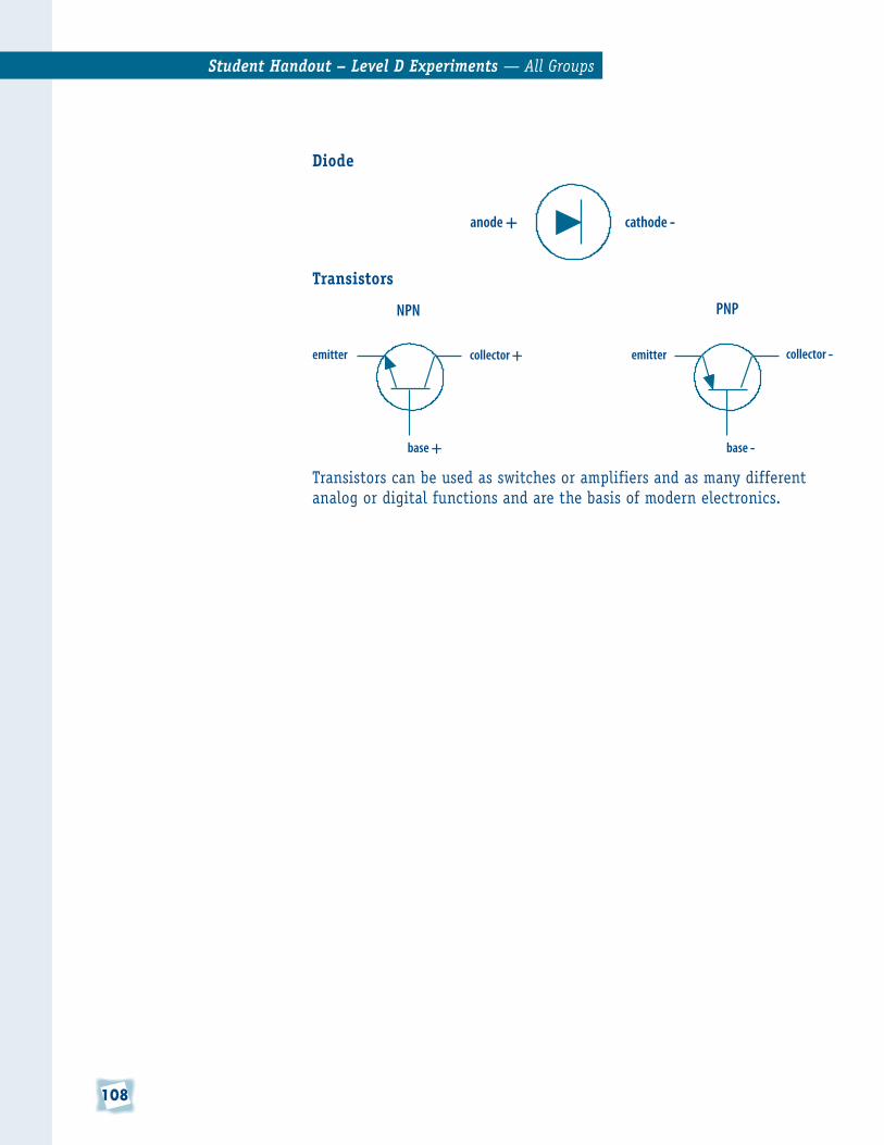
Diode
Transistors
Transistors can be used as switches or amplifiers and as many different analog or digital functions and are the basis of modern electronics.
Student Handout – Level D Experiments —AllGroups
anode + cathode -
NPN PNP
emitter collector + emitter collector -
base + base -

10�
Student Handout – Level D Experiments —AllGroups
Alternating Current (AC)All of our experiments involve using DC (direct current) because it is easily available from batteries and is safe since it is not connected to a larger power source. We know that DC is direct current that flows through a device from negative to positive. So what is AC?
Alternating current (AC) is continuously changing its polarity, always becoming more or less positive or negative. This change occurs because of the circular motion of a turning generator and the resulting alternating currents that are induced by changing magnetic fields. The poles of a magnet have north and south poles, and if they are spinning around beside another magnet, the result is a magnetic field that is changing constantly.
The north and south poles of the two magnets try to attract and repel each other, which induces a constantly varying voltage or current if they were part of an electrical circuit.
Coils and capacitors have a different way of reacting in AC circuits than in DC circuits. These devices react differently based on the frequency of the alternating current (how many times a second the AC “wave” cycles or goes high and low). This “ reactance” is how radios, for example, tune into a station like 104.5 MHZ (MHZ, by the way, is megahertz. A megahertz is one million cycles per second).
S
N
Fixed Magnet
N
S
Spinning Magnet Electromagnetic Reaction (attract or repel)
Time
Curre
ntAttract
Repel

110
Notes

111
Notes

11�
Notes