Chairs Overview - ProSites, Inc.c1-preview.prosites.com/106982/wy/docs/Adec 1021 -...
64
85.0812.00, 2003 CH-1 Chairs Overview A-dec model 1040, 1021 and 8000 chairs are electronically controlled, hydraulically powered dental chairs. Buttons on both the touchpad and 8-button footswitch and actuators on the 8-function footswitch are used to position and program auto-positioning functions into the chair. The hydraulic system is controlled by the electronic control module using relays and solenoid- actuated valves. This section provides information related to locating serial/model numbers, servicing, maintenance, and adjustment of chairs. Detail on how to service chairs and troubleshoot specific problems related to them is presented.
Transcript of Chairs Overview - ProSites, Inc.c1-preview.prosites.com/106982/wy/docs/Adec 1021 -...
85.0812.00, 2003 CH-1
Chairs Overview
A-dec model 1040, 1021 and 8000 chairs are electronically controlled, hydraulically powered dental chairs. Buttons on both the touchpad and 8-button footswitch and actuators on the 8-function footswitch are used to position and program auto-positioning functions into the chair.The hydraulic system is controlled by the electronic control module using relays and solenoid-actuated valves.
This section provides information related to locating serial/model numbers, servicing, maintenance, and adjustment of chairs. Detail on how to service chairs and troubleshoot specificproblems related to them is presented.

Locating Serial/Model Number
85.0812.00, 2003 CH-2
Chairs Serial/Model Number Locations
Cascade 1040 ChairDecade 1021/1011 Chair
Serial number label location
Serial number label location
The serial/model number tags identify the chair model and manufacture date. The label can befound either on the top surface of a chair’s upper structure (raise the toeboard) or on the right-hand side of the upper structure. If you have difficulty locating the serial/model number label, the following example may be helpful.

85.0812.00, 2003 CH-3
Chairs Manufacture Date
® 2601 CRESTVIEW DRIVENEWBERG, OREGON 97132 USA
Designated EU Representative: A-dec Dental U.K., Ltd.Austin House, 11 Liberty Way, Attleborough Fields,
Nuneaton, Warwickshire, England CV 116RZTele: (44) 1203-350901
DENTAL CHAIR
DENTAL CHAIR
MADE INUSA INPUTS
-
2001
REF: 1040 S/N: J167856
120 V 10 AMPS MAX50-60 Hz!
®C US
LISTED15VJ
CAUTION!
LA BEL P/N: 051.515.02 REV L
Serial/Model Number Label
Reading theManufacture Date
1
Item # Description
1 Model number
2 The first letter of the serial number indicates the month the product wasmanufactured; e.g., A is January.
3 First digit indicates the year of manufacture.
21
Different models of the chair can be identified by referring to the “REF” number. Each chair is furtheridentified by its month and year of manufacture.
This example shows how to identify the model and month and year of manufacture of the chair.
85.0812.00, 2003 CH-4
Chairs Hydraulics
Working with Hydraulics
Part Description
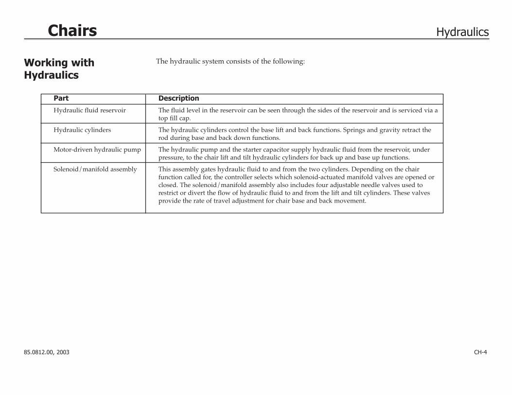
Hydraulic fluid reservoir The fluid level in the reservoir can be seen through the sides of the reservoir and is serviced via atop fill cap.
Hydraulic cylinders The hydraulic cylinders control the base lift and back functions. Springs and gravity retract therod during base and back down functions.
Motor-driven hydraulic pump The hydraulic pump and the starter capacitor supply hydraulic fluid from the reservoir, underpressure, to the chair lift and tilt hydraulic cylinders for back up and base up functions.
Solenoid/manifold assembly This assembly gates hydraulic fluid to and from the two cylinders. Depending on the chair function called for, the controller selects which solenoid-actuated manifold valves are opened orclosed. The solenoid/manifold assembly also includes four adjustable needle valves used torestrict or divert the flow of hydraulic fluid to and from the lift and tilt cylinders. These valvesprovide the rate of travel adjustment for chair base and back movement.
The hydraulic system consists of the following:
85.0812.00, 2003 CH-5
Chairs Hydraulic System Flow Diagram
MIN
MAX
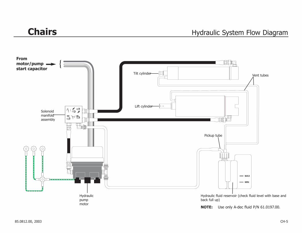
Frommotor/pump start capacitor
Solenoid manifold assembly
Tilt cylinder
Lift cylinder
Vent tubes
Pickup tube
Hydraulic fluid reservoir (check fluid level with base andback full up)
NOTE: Use only A-dec fluid P/N 61.0197.00.
Hydraulicpumpmotor

85.0812.00, 2003 CH-6
Chairs Hydraulic Manifold
Hydraulic Manifold
Item # Part Number Description
1 61.1335.00 Solenoid, (8-watt, 100V, Yellow wires)
61.1336.00 Solenoid, (8-watt, 120 V, Black wires)
61.1337.00 Solenoid, (8-watt, 240 V,Red wires)
2 035.041.02 O-ring, special pkg 10
3 030.004.02 O-ring, AS568-004 pkg 10
4 030.010.00 O-ring, AS568-010 (only on dual-block manifolds)
5 61.0460.00 Flow adjust screw with o-ring
6 001.002.00 Screw, truss-head slot
1
2
3
4
56
33
Before January 1999

85.0812.00, 2003 CH-7
Chairs Hydraulic Manifold
Hydraulic Manifold
Item # Part Number Description
1 61.1335.01 Solenoid, (8-watt, 100V, Yellow wires)
61.1336.01 Solenoid, (8-watt, 120V, Black wires)
61.1337.01 Solenoid, (8-watt, 240V,Red wires)
2 030.015.02 O-ring, pkg 10
3 030.004.02 O-ring, AS568-004 pkg 10
4 61.0460.00 Flow adjust screw with o-ring
5 002.118.01 Screw, button-head, socket
6 61.1332.00 Manifold assy, hyd, 100V61.1333.00 Manifold assy, hyd, 120V61.1334.00 Manifold assy, hyd, 240V
3
4
5
2
6
1
3
After January 1999
85.0812.00, 2003 CH-8
Chair Hydraulic Manifold
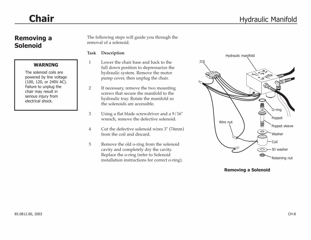
The following steps will guide you through theremoval of a solenoid.
Task Description
1 Lower the chair base and back to the full down position to depressurize the hydraulic system. Remove the motor pump cover, then unplug the chair.
2 If necessary, remove the two mountingscrews that secure the manifold to thehydraulic tray. Rotate the manifold so the solenoids are accessible.
3 Using a flat blade screwdriver and a 9/16"wrench, remove the defective solenoid.
4 Cut the defective solenoid wires 3" (74mm)from the coil and discard.
5 Remove the old o-ring from the solenoid cavity and completely dry the cavity.Replace the o-ring (refer to Solenoid installation instructions for correct o-ring).
Hydraulic manifold
O-ring
Poppet sleeve
Washer
ID washer
Retaining nut
Poppet
Coil
Wire nut
J10
Removing aSolenoid
WARNING
The solenoid coils arepowered by line voltage(100, 120, or 240V AC).Failure to unplug thechair may result in serious injury from electrical shock.
Removing a Solenoid

85.0812.00, 2003 CH-9
Chair Hydraulic Manifold
The following steps will guide you through replacing a solenoid.
Task Description
1 Install the new solenoid stem and poppet intothe manifold and tighten to 35-40 in lb (.11085-.2284 Nm). Position the remaining solenoid parts on the stem and secure by tightening the retaining nut to 25-30 in lb (.14275-.1713 Nm).
2 Cut the solenoid wires 3" (75 mm) from the coil.Install the stripped wires from the solenoid andthe connector housing into a wire nut. Repeatfor the remaining wire.
3 Using the mounting screws, secure the manifold to the hydraulic tray.
4. Plug in the chair. Test the chair functions toensure proper operations and that no fluid leakage occurs. Reinstall the motor pump cover.
Hydraulic manifold
O-ring
Poppet sleeve
Washer
ID washer
Retaining nut
Poppet
Coil
Wire nut
J10
Replacing aSolenoid
WARNING
The solenoid coils arepowered by line voltage(100, 120, or 240V AC).Failure to unplug thechair may result in serious injury from electrical shock.
Replacing a Solenoid
85.0812.00, 2003 CH-10
Chairs Hydraulic Manifold
Base down control valve
Base up control valve
Back down control valve
Back upcontrol valve
CAUTION
Do not completely closea speed control valve. The motor/pump couldoverheat and becomedamaged from pumpingagainst a closed valve.Do not remove retainingscrew from the controlvalves.
Retainingscrew
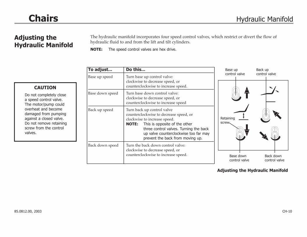
The hydraulic manifold incorporates four speed control valves, which restrict or divert the flow ofhydraulic fluid to and from the lift and tilt cylinders.
NOTE: The speed control valves are hex drive.
To adjust... Do this...
Base up speed Turn base up control valve:clockwise to decrease speed, orcounterclockwise to increase speed.
Base down speed Turn base down control valve:clockwise to decrease speed, or counterclockwise to increase speed
Back up speed Turn back up control valvecounterclockwise to decrease speed, orclockwise to increase speed. NOTE: This is opposite of the other
three control valves. Turning the backup valve counterclockwise too far mayprevent the back from moving up.
Back down speed Turn the back down control valve:clockwise to decrease speed, orcounterclockwise to increase speed.
Adjusting the Hydraulic Manifold
Adjusting the Hydraulic Manifold

85.0812.00, 2003 CH-11
Chairs Hydraulic Manifold
Task Description
1 Remove the motor/pump cover from the chair.
2 Fit a 5/8" wrench to the high pressure outlet port(either lift or tilt, whichever is in hydrostatic lock) ofthe hydraulic manifold. Hold the port still and use a9/16" wrench to loosen the hose fitting.
3 Place a shop rag around the fitting to absorb the fluid.
4 Carefully loosen the fitting counterclockwise until oilbegins to leak from the fitting. Retighten the fitting.Operate the down function. A second release ofhydraulic fluid may be required.
5 Adjust the limit switch that caused the hydrostaticlock (refer to Adjusting the Base Up Limit Switch). Insome cases, it may be necessary to remove andreplace the limit switch. Adjust the new limit switchas needed. Also ensure that the large gear/actuatoris securely installed and not slipping.
6 Cycle the chair a couple of times to verify it is nolonger in hydrostatic lock.
Tilt cylinderhigh pressure fitting
Lift cylinderhigh pressure fitting
Correcting Hydrostatic Lock
Hydraulic lock occurs based on the following conditions:
• chair base or back is stuck in full up position
• limit switch not activated, or
• down solenoid poppet is unable to open based on excess hydraulic pressure.
Correcting Hydrostatic Lock
85.0812.00, 2003 CH-12
Chairs Electrical System Wiring Diagram
P17
P5
P2
P1
S1
P4
S2
P6
BSPO
TB
KPO
T
B KUPPRGM
BEEP
ER
PUM
P
(100
-120
V~)
N/L2
DS3
DS5
DS12
DS8
P14CUSP STATUS
P16
P12P11
DS15
BK UP
DS14
DS7
DS13
DS4
BS UP BK UP
BS UP
BS DN
BK DN
N/L2
BS DN
BK DN
PUMPK5
PUMPP9
LOCKOUTP13
DS1
DS16DS17
DS2
DS11
DS6
DS9
DS10
+12V +5V
BSUPBSDNB KDNPRGM 0PRGM 1PRGM 2PRGM 3EN/DIS TP/FSFA CT DEFAULTB K POTBS POTSPARESPARE
TEST POINTS
P10
L1 N/L2L1 N/L2
AUXILIARYOUTPUT POWER
(2A MAX)
MAINSINPUT POWER
1 2
ON
R74
R72
R73
#1 #2 SETSOFFONOFFON
OFFOFFONON
CUSP/RETLAST POSTPRGM 3NOT USED
CB2
CB1
BSB
KS
P
(220
-240
V~)
PART
#
"STATIC SENSITIVE"
1 2
30
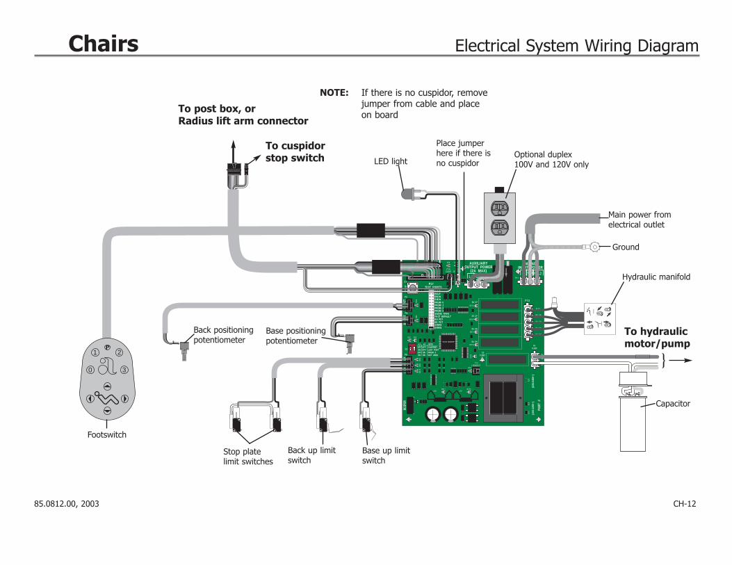
Optional duplex100V and 120V only
Ground
Footswitch
LED light
Back positioningpotentiometer
Base positioningpotentiometer
Main power fromelectrical outlet
Hydraulic manifold
To post box, or Radius lift arm connector
Stop platelimit switches
Base up limitswitch
Back up limitswitch
Capacitor
To hydraulicmotor/pump
To cuspidor stop switch
NOTE: If there is no cuspidor, removejumper from cable and place on board
Place jumperhere if there isno cuspidor

85.0812.00, 2003 CH-13
Chairs Electrical Systems Service Parts
Item # Part Number Description
1 61.1332.00 100V, Yellow wires61.1333.00 120V, Black wires61.1334.00 240V, Red wires
2 90.1031.00 Capacitor with boot (100-120V)90.1034.00 Capacitor with boot (240V)
3 041.372.00 Positioning potentiometer
4 61.2065.00 Back up limit switch
5 044.184.01 Base up limit switch
6 61.2099.00 Cable assy, tilt switch(1040) only
7 61.3043.00 8-button footswitch
8 39.1045.00 Chair touchpad39.1385.00 Performer touchpad39.1090.00 Cascade Master with cuspidor39.1090.00 Cascade Master w/o cuspidor
To Replace Circuit Board P/N Order this kit
61.2510.00 90.1029.00 (100-120V)61.1214.0161.1373.01
61.2512.00 90.1029.01(220-240V)61.1217.01
1
2
3
4 5
6
7
3
21
0
8

CH-14
Chairs Diagnostic LEDs for the Circuit Board
LEDs
NOTE: Refer to Testing Factory Defaultsfor more details.
DS1DS2
DS3
DS7
DS8
DS9
DS10
DS11
DS12
DS13
DS4
DS5
DS6
DS14
DS15
DS16DS17
R73
R72
R74
85.0812.00, 2003
85.0812.00, 2003 CH-15
Chairs Diagnostic LEDs for the Circuit Board
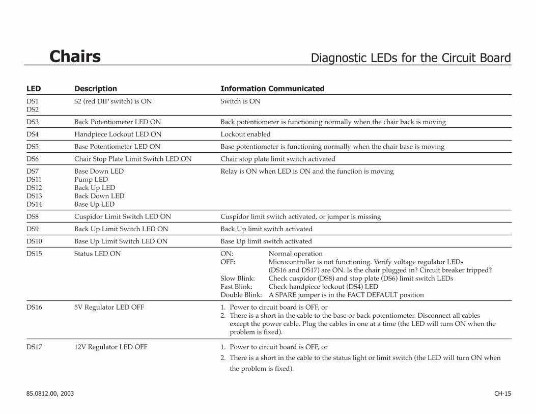
LED Description Information Communicated
DS1 S2 (red DIP switch) is ON Switch is ONDS2
DS3 Back Potentiometer LED ON Back potentiometer is functioning normally when the chair back is moving
DS4 Handpiece Lockout LED ON Lockout enabled
DS5 Base Potentiometer LED ON Base potentiometer is functioning normally when the chair base is moving
DS6 Chair Stop Plate Limit Switch LED ON Chair stop plate limit switch activated
DS7 Base Down LED Relay is ON when LED is ON and the function is movingDS11 Pump LEDDS12 Back Up LEDDS13 Back Down LEDDS14 Base Up LED
DS8 Cuspidor Limit Switch LED ON Cuspidor limit switch activated, or jumper is missing
DS9 Back Up Limit Switch LED ON Back Up limit switch activated
DS10 Base Up Limit Switch LED ON Base Up limit switch activated
DS15 Status LED ON ON: Normal operationOFF: Microcontroller is not functioning. Verify voltage regulator LEDs
(DS16 and DS17) are ON. Is the chair plugged in? Circuit breaker tripped?Slow Blink: Check cuspidor (DS8) and stop plate (DS6) limit switch LEDsFast Blink: Check handpiece lockout (DS4) LEDDouble Blink: A SPARE jumper is in the FACT DEFAULT position
DS16 5V Regulator LED OFF 1. Power to circuit board is OFF, or2. There is a short in the cable to the base or back potentiometer. Disconnect all cables
except the power cable. Plug the cables in one at a time (the LED will turn ON when the problem is fixed).
DS17 12V Regulator LED OFF 1. Power to circuit board is OFF, or
2. There is a short in the cable to the status light or limit switch (the LED will turn ON when
the problem is fixed).

85.0812.00, 2003 CH-16
Chairs Chair Printed Circuit Board (PCB)
Testing and Programmingthe Circuit Board
WARNING
The chair will begin tomove automatically during this test; to avoidinjury or equipment damage, remove all possible obstructions andmaintain a safe distancefrom the chair. To interrupt the chair cycle,press any button on thetouchpad or footswitch,or activate the chair stop plate.
Follow these steps to test and program the chair circuit board.
Task Description
1 Insert the SPARE jumper into the FACT DEFAULT location (on P17).
Result: The chair will cycle the base and back movements and automaticallyreprogram the memory positions to the factory settings (position 0 to entry/exit; 1 and 2 to the same pre-programmed positions; and 3 to cuspidor/return).
If the circuit board beeps three times, continue with step two. If the circuit board beeps just once, the chair cycle has been interrupted. Diagnoseand correct any errors, then press either circuit breaker for five seconds to restartthe cycle (refer to Testing Factory Defaults).
2 Move the jumper from the FACT DEFAULT location (on P17) back to the SPARE location. NOTE: The jumper must be in the SPARE position for normal chair functions and
safe operation.
3 Press “1” on the touchpad or footswitch, or the green position on the 8-function footswitch.
Result: The chair will move to the operating position.
4 Press “0” on the touchpad or footswitch, or the red button on the 8-functionfootswitch.
Result: The chair will move to the entry/exit position.NOTE: The chair programmable position buttons can be reprogrammed to the
desired positions as specified by the dental team.
85.0812.00, 2003 CH-17
Chairs Tests
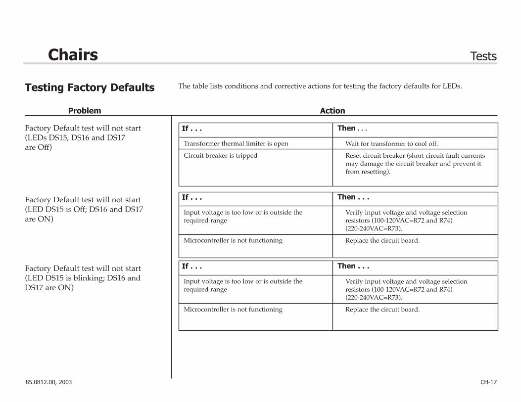
Problem Action
Factory Default test will not start(LEDs DS15, DS16 and DS17 are Off)
Factory Default test will not start(LED DS15 is Off; DS16 and DS17are ON)
Factory Default test will not start (LED DS15 is blinking; DS16 andDS17 are ON)
If . . . Then . . .
Transformer thermal limiter is open
Circuit breaker is tripped
Wait for transformer to cool off.
Reset circuit breaker (short circuit fault currentsmay damage the circuit breaker and prevent itfrom resetting).
If . . . Then . . .
Input voltage is too low or is outside therequired range
Microcontroller is not functioning
Verify input voltage and voltage selection resistors (100-120VAC=R72 and R74) (220-240VAC=R73).
Replace the circuit board.
If . . . Then . . .
Input voltage is too low or is outside therequired range
Microcontroller is not functioning
Verify input voltage and voltage selection resistors (100-120VAC=R72 and R74) (220-240VAC=R73).
Replace the circuit board.
Testing Factory Defaults The table lists conditions and corrective actions for testing the factory defaults for LEDs.

85.0812.00, 2003 CH-18
Chairs Tests
Problem Action
Factory Default test halts duringthe BASE UP test and the PCBboard beeps one time
Factory Default test halts duringthe BACK DOWN test and PCBboard beeps one time
If . . . Then . . .
Input voltage is too low or is outside therequired range
Base Up limit switch is activated
Motor thermal limiter is open, motor is hot
Motor capacitor is defective
Base Up solenoid is defective
Base is in hydrostatic lock
Potentiometer is not changing voltage
Verify input voltage and voltage selection resistors (100-120VAC=R72 and R74 (220-240VAC=R73).
Verify switch operation.
Wait for motor to cool off.
Test capacitor and replace, if needed.
Test solenoid and replace, if needed.
Refer to Correcting Hydrostatic Lock.
Verify potentiometer LED comes ON when baseis moving.
Check potentiometer mechanical drive and electrical connections.
If . . . Then . . .
Stop plate limit switch is activated
Stop plate is jammed
Back Down solenoid is defective
Back is in hydrostatic lock
Potentiometer is not changing voltage
Verify switch operation.
Remove and reinstall the stop plate.
Test solenoid and replace if needed.
Refer to Correcting Hydrostatic Lock.
Verify potentiometer LED is ON when back is moving.
Check potentiometer mechanical drive and electrical connections.

85.0812.00, 2003 CH-19
Chairs Tests
Problem Action
Factory Default test halts duringthe BACK UP test
Factory Default test halts duringthe BASE DOWN test
Chair moves by itself when poweris turned ON
If . . . Then . . .
Back up limit switch is activated
Back Up solenoid is defective
Back is in hydrostatic lock
Potentiometer is not changing voltage
Verify switch operation.
Test solenoid and replace, if needed.
Refer to the Correcting Hydrostatic Lock.
Verify potentiometer LED is ON when back is moving.
Check potentiometer mechanical drive and electrical connections.
If . . . Then . . .
Stop plate limit switch is activated
Base Down solenoid is defective
Base is in hydrostatic lock
Potentiometer is not changing voltage
Verify switch operation.
Test solenoid and replace if needed.
Refer to Correcting Hydrostatic Lock.
Verify potentiometer LED is ON when base is moving.
Check potentiometer mechanical drive and electrical connections.
If . . . Then . . .
The jumper is in FACT DEFAULT position
Short circuit in touchpad or footswitch
Short circuit on circuit board
Verify that the jumper is in the SPARE position.
Unplug the touchpad and footswitch; reset thecircuit breaker. If the problem isn’t repeated, thetouchpad or footswitch may have shorted.
Replace the circuit board.
Chairs Chair Printed Circuit Board (PCB)
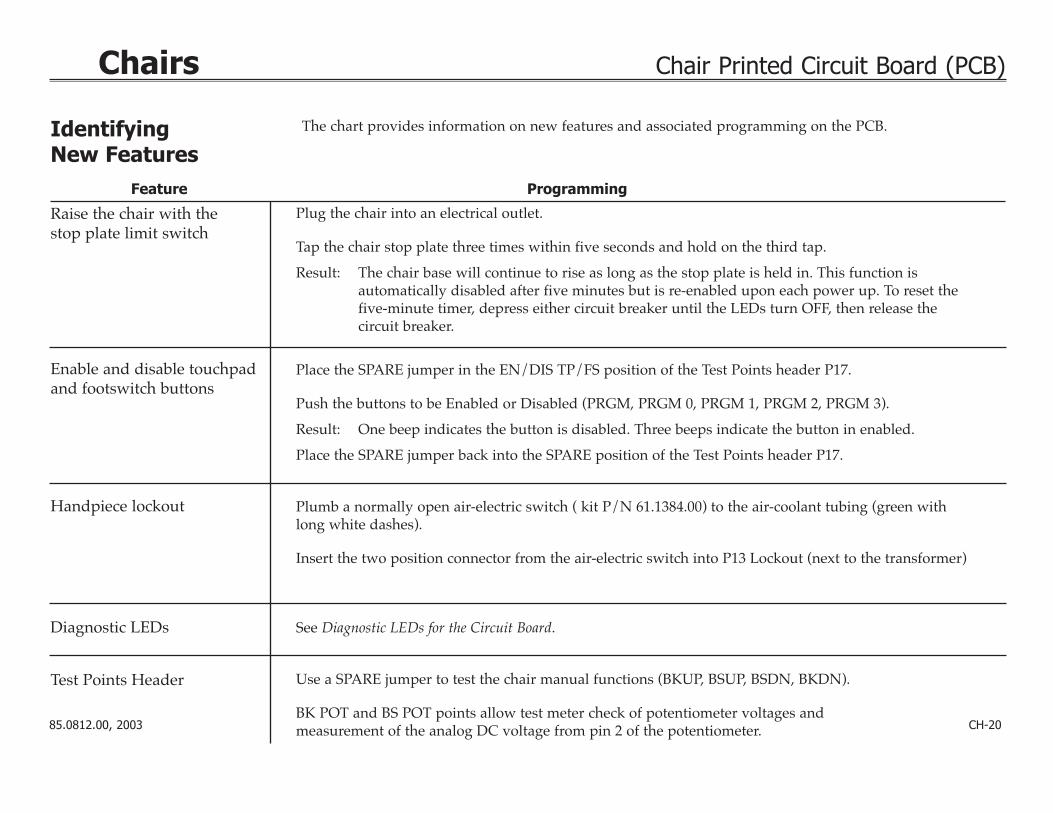
Raise the chair with the stop plate limit switch
Enable and disable touchpad and footswitch buttons
Handpiece lockout
Diagnostic LEDs
Test Points Header
Plug the chair into an electrical outlet.
Tap the chair stop plate three times within five seconds and hold on the third tap.
Result: The chair base will continue to rise as long as the stop plate is held in. This function is automatically disabled after five minutes but is re-enabled upon each power up. To reset the five-minute timer, depress either circuit breaker until the LEDs turn OFF, then release the circuit breaker.
Place the SPARE jumper in the EN/DIS TP/FS position of the Test Points header P17.
Push the buttons to be Enabled or Disabled (PRGM, PRGM 0, PRGM 1, PRGM 2, PRGM 3).
Result: One beep indicates the button is disabled. Three beeps indicate the button in enabled.
Place the SPARE jumper back into the SPARE position of the Test Points header P17.
Plumb a normally open air-electric switch ( kit P/N 61.1384.00) to the air-coolant tubing (green withlong white dashes).
Insert the two position connector from the air-electric switch into P13 Lockout (next to the transformer)
See Diagnostic LEDs for the Circuit Board.
Use a SPARE jumper to test the chair manual functions (BKUP, BSUP, BSDN, BKDN).
BK POT and BS POT points allow test meter check of potentiometer voltages andmeasurement of the analog DC voltage from pin 2 of the potentiometer.
Feature Programming
The chart provides information on new features and associated programming on the PCB.
CH-2085.0812.00, 2003
Identifying New Features

85.0812.00, 2003 CH-21
Chairs Electrical System Wiring Diagram (for PCB with no LEDs)9412P
otter & B
rumfield
T90S
1D12-24
Coil: 24V
DC
30A, 240V
AC
MA
DE
IN U
.S.A
.
9412P
otter & B
rumfield
T90S
1D12-24
Coil: 24V
DC
30A, 240V
AC
MA
DE
IN U
.S.A
.
10A, 240V
AC
15A, 125V
AC
9412
Pot
ter
& B
rum
field
T90
S1D
12-2
4C
oil:
24V
DC
30A
, 240
VA
C
MA
DE
IN U
.S.A
.
10A
, 240
VA
C15
A, 1
25V
AC
9412
Pot
ter
& B
rum
field
T90
S1D
12-2
4C
oil:
24V
DC
30A
, 240
VA
C
MA
DE
IN U
.S.A
.
10A
, 240
VA
C15
A, 1
25V
AC
9412
Pot
ter
& B
rum
field
T90
S1D
12-2
4C
oil:
24V
DC
30A
, 240
VA
C
MA
DE
IN U
.S.A
.
10A
, 240
VA
C15
A, 1
25V
AC
12
43
56
87
P9
P12
P11
P1
P5
P4
P14 CUSPP7
P10
P6
S1
S2
12
ON
- - - - - - - - - - - - - - - - - - - #1 #2 SETS
OFF OFF sCUSP/RETON OFF LAST POSOFF ON PRGM 3
ENTR
TESTPOINTS
EXIT
BSDN
BSUP
Bk DN
Bk UP
9412
Pot
ter
& B
rum
field
T90
S1D
12-2
4C
oil:
24V
DC
30A
, 240
VA
C
MA
DE
IN U
.S.A
.
10A
, 240
VA
C15
A, 1
25V
AC
9412P
otter & B
rumfield
T90S
1D12-24
Coil: 24V
DC
30A, 240V
AC
MA
DE
IN U
.S.A
.
10A, 240V
AC
15A, 125V
AC
9412P
otter & B
rumfield
T90S
1D12-24
Coil: 24V
DC
30A, 240V
AC
MA
DE
IN U
.S.A
.
10A, 240V
AC
15A, 125V
AC
9412
30A
, 240
VA
C
MA
DE
IN U
.S.A
.
10A
, 240
VA
C15
A, 1
25V
AC
9412
Pot
ter
& B
rum
field
T90
S1D
12-2
4C
oil:
24V
DC
30A
, 240
VA
C
MA
DE
IN U
.S.A
.
10A
, 240
VA
C15
A, 1
25V
AC
12
43
56
87
T90
S1D
12-2
4C
oil:
24V
DC
Pot
ter
& B
rum
field
T90
S1D
12-2
4C
oil:
24V
DC
1 2
30
Item # Part Number Description
1 61.3043.00 8-button footswitch
2 041.372.00 Back positioning potentiometer
3 041.372.00 Base positioning potentiometer
4 61.2065.00 Back up limit switch
5 044.184.01 Base up limit switch
1
2
4 5
3
Back
Base
LED light
Printedcircuit board
See next page
To post box, or Radius liftarm connector
To cuspidorstop switch
85.0812.00, 2003 CH-22
Chairs Electrical System Wiring Diagram (for PCB with no LEDs)
9412P
otter & B
rumfield
T90S
1D12-24
Coil: 24V
DC
30A, 240V
AC
MA
DE
IN U
.S.A
.
10A, 240V
AC
15A, 125V
AC
9412P
otter & B
rumfield
T90S
1D12-24
Coil: 24V
DC
30A, 240V
AC
MA
DE
IN U
.S.A
.
10A, 240V
AC
15A, 125V
AC
9412
Pot
ter
& B
rum
field
T90
S1D
12-2
4C
oil:
24V
DC
30A
, 240
VA
C
MA
DE
IN U
.S.A
.
10A
, 240
VA
C15
A, 1
25V
AC
9412
Pot
ter
& B
rum
field
T90
S1D
12-2
4C
oil:
24V
DC
30A
, 240
VA
C
MA
DE
IN U
.S.A
.
10A
, 240
VA
C15
A, 1
25V
AC
9412
Pot
ter
& B
rum
field
T90
S1D
12-2
4C
oil:
24V
DC
30A
, 240
VA
C
MA
DE
IN U
.S.A
.
10A
, 240
VA
C15
A, 1
25V
AC
12
43
56
87
P9
P12
P11P2
P1
P5
P4
P14 CUSPP7
P10
P6
S1
S2
100 - 120 V
12
ON
- - - - - - - - - - - - - - - - - - - #1 #2 SETS
OFF OFF sCUSP/RETON OFF LAST POSOFF ON PRGM 3ON ON DUPLEX
ENTR
TESTPOINTS
EXIT
BSDN
BSUP
Bk DN
Bk UP
A-DEC 61-1215-00 REV L ASSY 61-1214-01 REV E
MA
DE
IN U
.S.A
.
15A, 125V
AC
9412
Pot
ter
& B
rum
field
9412
Pot
ter
& B
rum
field
P2
P1
P5
P4
P14 CUSPP7
P6
S1
S2
12
ON
- - - - - - - - - - - - - - - - - - - #1 #2 SETS
OFF OFF CUSP/RETON OFF LAST POSOFF ON PRGM 3ON ON DUPLEX
ENTR
TESTPOINTS
EXIT
BSDN
BSUP
Bk DN
Bk UP
115V
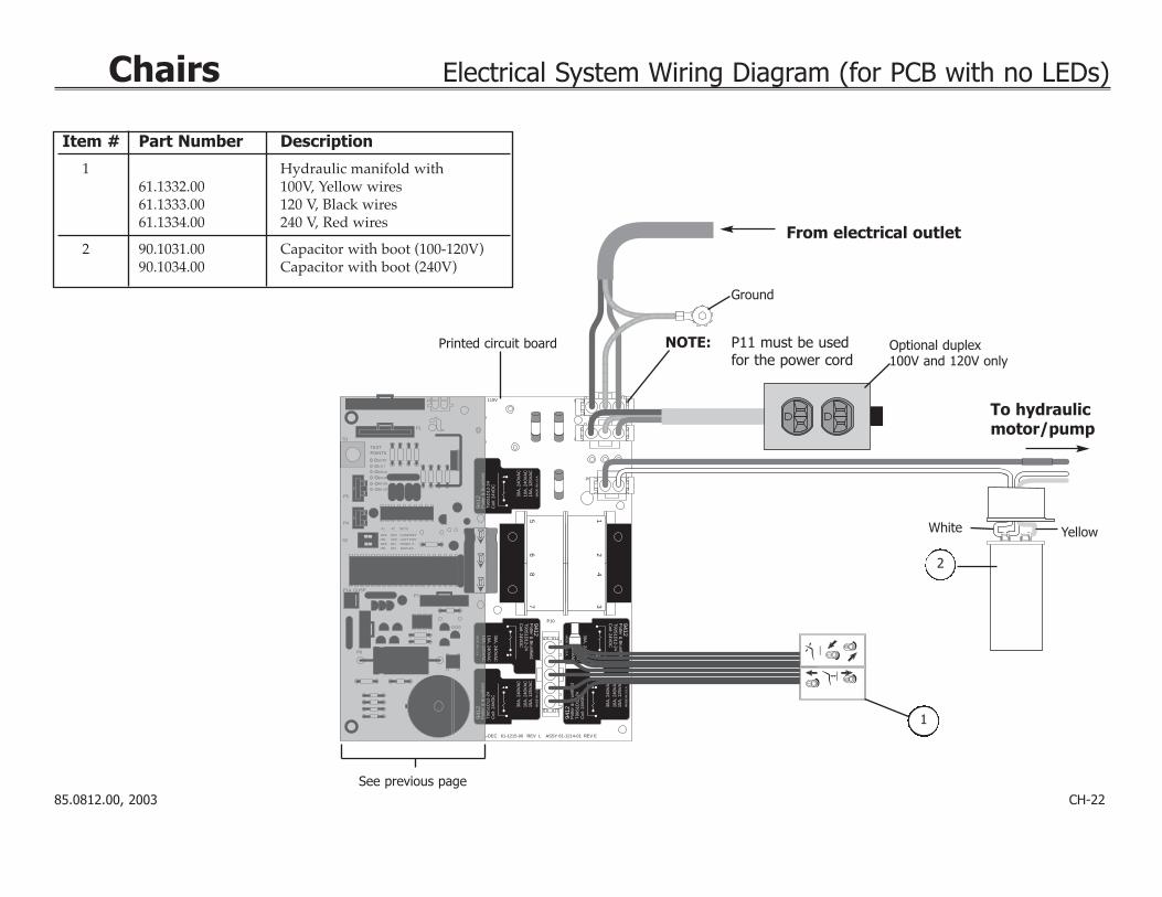
From electrical outlet
Ground
Optional duplex 100V and 120V only
Item # Part Number Description
1 Hydraulic manifold with61.1332.00 100V, Yellow wires61.1333.00 120 V, Black wires61.1334.00 240 V, Red wires
2 90.1031.00 Capacitor with boot (100-120V)90.1034.00 Capacitor with boot (240V)
1
2
To hydraulic motor/pump
See previous page
Printed circuit board NOTE: P11 must be usedfor the power cord
White Yellow

85.0812.00, 2003 CH-23
Chairs Fuse Table for Old-style Circuit Boards (no LEDs)
Amps Description Where used Part Number
.125 3AG, Slo-Blo, 250V Chairs, 100/120V 041.360.00
.150 3AG, Slo-Blo, 250V Chairs, 240V 046.126.00
.300 3AG, Slo-Blo, 250V 1040, 1030 Chairs 100/120V 046.069.001010/1015/1020/1021 Chair, 120V1010/1020 Chair, 100V1005 Priority Chair 240V
.375 3AG, Slo-Blo, 250V Transformer 120V/24V Accessory 046.021.00
.600 3AG, Slo-Blo, 250V 1005 Priority Chair 100/120V 046.070.00
5.0 3AG, Slo-Blo, 250V Chairs 240V UK 046.100.00
Slo-Blo Fuses 3AG, 1 1/4" X 1/4" (31.75mm X 6.35mm)
Time Lag Fuses, 5mm X 20mm (1/5" X 3/4")
Actual Size
Actual Size
NOTE: There are no replaceable fuses on the following circuit boards:90.1029.00 (100-120V) and 90.1029.01 (220-240V).
*Decade chairs after E863254; Cascade chairs after E863116
Amps Description Where used Part Number
.040 Time Lag, 250V Chairs 230V* 044.194.00
.063 Time Lag, 250V Chairs 115V* 044.193.00
6.30 Time Lag, 250V Chairs 230V* 044.147.00
10.0 Time Lag, 250V Chairs 115V* 044.192.00
85.0812.00, 2003 CH-24
Chairs Cascade 1040 Back Positioning Potentiometer and Limit Switch
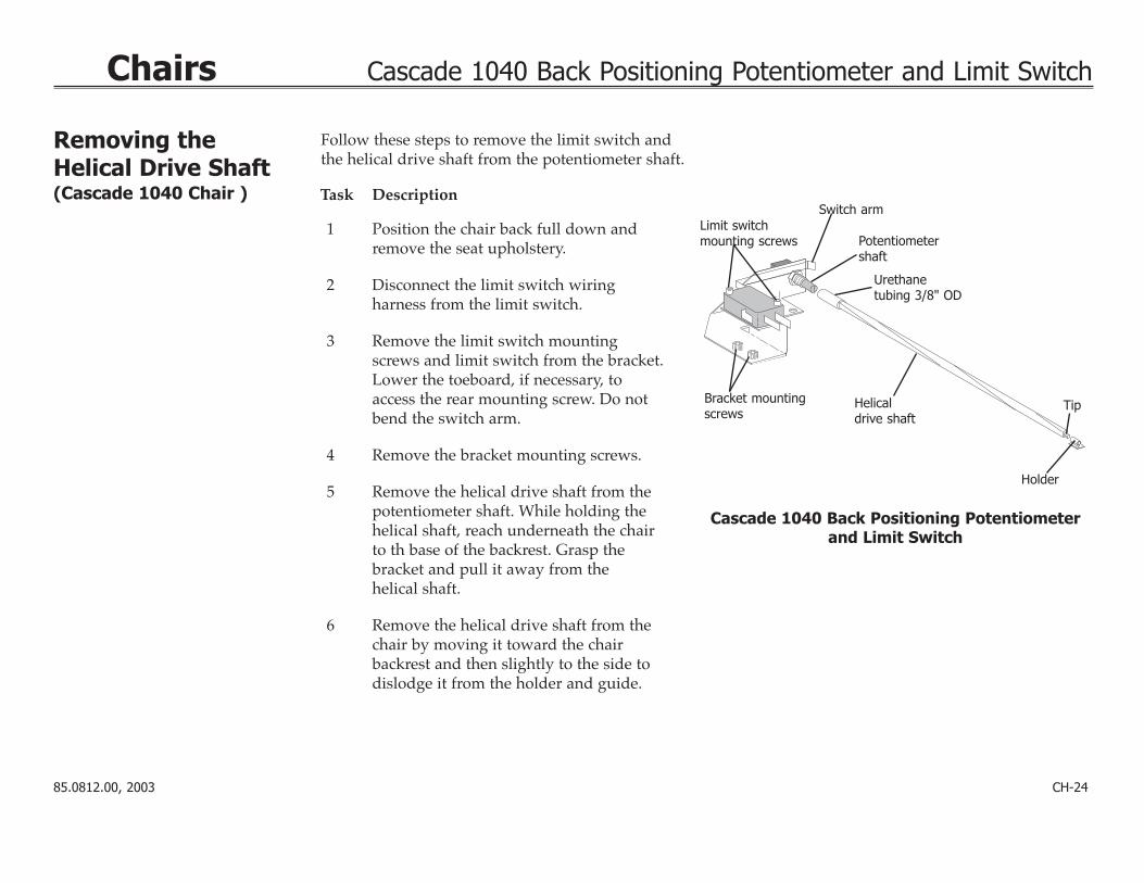
Removing theHelical Drive Shaft(Cascade 1040 Chair ) Task Description
1 Position the chair back full down andremove the seat upholstery.
2 Disconnect the limit switch wiring harness from the limit switch.
3 Remove the limit switch mountingscrews and limit switch from the bracket.Lower the toeboard, if necessary, toaccess the rear mounting screw. Do notbend the switch arm.
4 Remove the bracket mounting screws.
5 Remove the helical drive shaft from thepotentiometer shaft. While holding thehelical shaft, reach underneath the chairto th base of the backrest. Grasp thebracket and pull it away from the helical shaft.
6 Remove the helical drive shaft from thechair by moving it toward the chair backrest and then slightly to the side todislodge it from the holder and guide.
Limit switchmounting screws
Switch arm
Potentiometershaft
Urethane tubing 3/8" OD
Bracket mountingscrews
Helicaldrive shaft
Holder
Cascade 1040 Back Positioning Potentiometerand Limit Switch
Tip
Follow these steps to remove the limit switch andthe helical drive shaft from the potentiometer shaft.
85.0812.00, 2003 CH-25
Chairs Cascade 1040 Back Positioning Potentiometer and Limit Switch
Reinstalling theHelical Drive Shaft (Cascade 1040 Chair) Task Description
1 Reinstall the helical drive shaft by fully inserting the tip through the guide and into the holder.
2 Install the helical shaft onto the potentiometer shaft.
3 Reinstall the mounting screws, being careful not to pinch any wires.
4 Reinstall the limit switch on the bracket and reconnect it with the wiring harness.
5 Ensure the positioning potentiometer electrical connections are complete.
6 Reprogram the auto-positioning functions (refer to Programming the Chair).
7 Reinstall the upholstery.
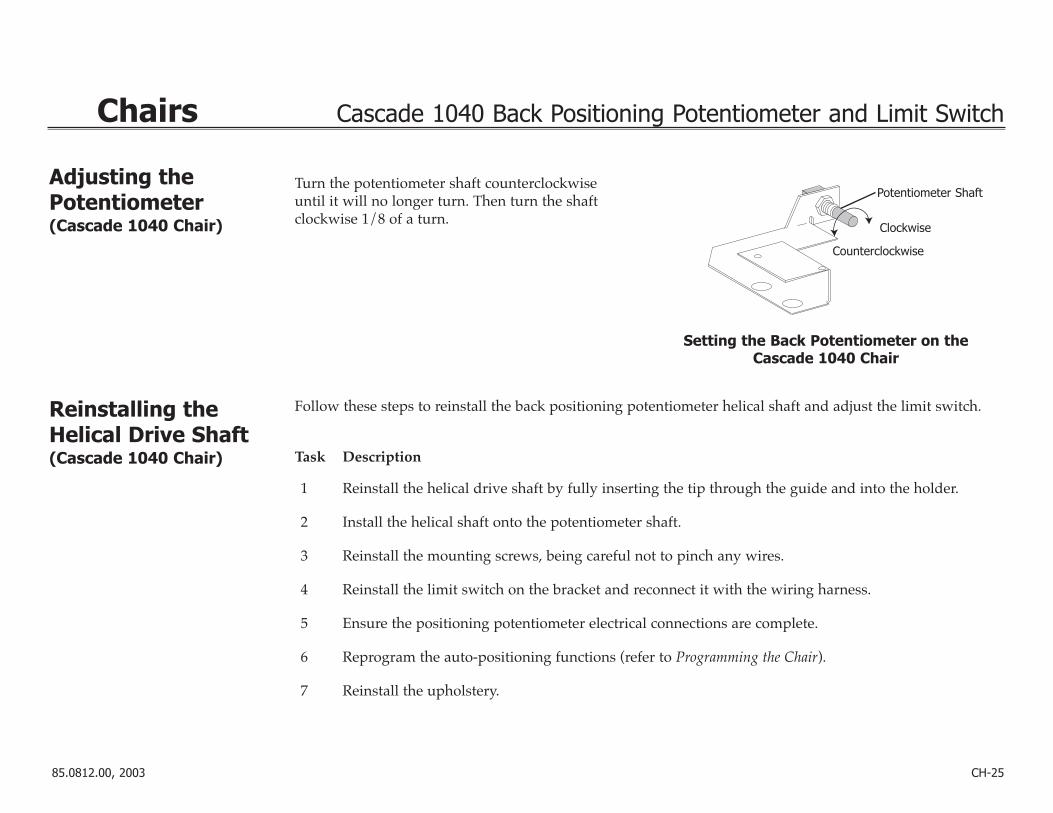
Adjusting thePotentiometer (Cascade 1040 Chair)
Turn the potentiometer shaft counterclockwiseuntil it will no longer turn. Then turn the shaftclockwise 1/8 of a turn.
Potentiometer Shaft
Clockwise
Setting the Back Potentiometer on the Cascade 1040 Chair
Counterclockwise
Follow these steps to reinstall the back positioning potentiometer helical shaft and adjust the limit switch.
85.0812.00, 2003 CH-26
Chairs Decade 1011/1021 Back Positioning Potentiometer and Limit Switch
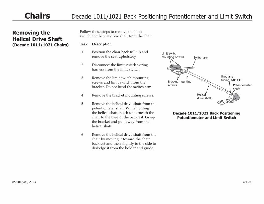
Removing the Helical Drive Shaft(Decade 1011/1021 Chairs) Task Description
1 Position the chair back full up andremove the seat upholstery.
2 Disconnect the limit switch wiring harness from the limit switch.
3 Remove the limit switch mountingscrews and limit switch from the bracket. Do not bend the switch arm.
4 Remove the bracket mounting screws.
5 Remove the helical drive shaft from thepotentiometer shaft. While holding the helical shaft, reach underneath thechair to the base of the backrest. Graspthe bracket and pull away from the helical shaft.
6 Remove the helical drive shaft from thechair by moving it toward the chairbackrest and then slightly to the side todislodge it from the holder and guide.
Limit switchmounting screws Switch arm
Potentiometershaft
Urethane tubing 3/8" ODBracket mounting
screws
Helicaldrive shaft
Decade 1011/1021 Back Positioning Potentiometer and Limit Switch
Tip
Follow these steps to remove the limitswitch and helical drive shaft from the chair.

85.0812.00, 2003 CH-27
Chairs Decade 1011/1021 Back Positioning Potentiometer and Limit Switch
Reinstalling theHelical Shaft (Decade 1011/1021Chairs)
Task Description
1 Reinstall the helical drive shaft by fully inserting the tip through the guide and into the holder.
2 Install the helical shaft onto the potentiometer shaft.
3 Reinstall the mounting screws, being careful not to pinch any wires.
4 Reinstall the limit switch on the bracket and reconnect it with the wiring harness.
5 Ensure the positioning potentiometer electrical connections are complete.
6 Reprogram the auto-positioning functions (refer to Programming the Chair).
7 Reinstall the upholstery.
Turn the potentiometer shaft clockwise untilit will no longer turn. Then turn the shaftcounterclockwise 1/8 of a turn.
Potentiometer shaft
Counterclockwise
Setting the Back Potentiometer on the Decade 1011/1021 Chair
Clockwise
Follow these steps to reinstall the back positioning potentiometer helical shaft and to reposition the limit switch.
Adjusting thePotentiometer(Decade 1011/1021 Chairs)

85.0812.00, 2003 CH-28
Chairs Cascade and Decade Base Positioning Potentiometer
Working with theBack and BasePositioningPotentiometers
The back and base positioning potentiometers (pots) perform two tasks for the controller:
• Provide the controller with a voltage level representing the current position of the chair base and back.The voltage level is stored by the controller for later reference during auto-positioning.
• Tell the controller where the chair base and back are currently positioned. The controller compares thecurrent voltage level to the voltage level stored during auto-positioning programming.
The base positioning pot is gear-driven by movement of the chair lift arm. The back positioning pot is driven by movement of the chair back.

85.0812.00, 2003 CH-29
Chairs Cascade and Decade Base Positioning Potentiometer
Adjusting theBase PositioningPotentiometer
Task Description
1 Remove the motor/pump cover andposition the chair base down.
2 Remove the mounting screw.
3 Turn the potentiometer gear clockwiseuntil it stops.
4 Align the potentiometer assembly, thenturn the potentiometer gear counterclockwise two teeth (relative toone tooth on the large drive gear).
5 Ensure all electrical connections to thelimit switch and positioning potentiometer are properly connected
6 Raise the chair base while observing thetwo gears for binding.
7 Reinstall the motor/pump cover and reprogram the pre-positioningfunctions.
Limit switch
Large drivegear
Potentiometer gear
Positioning potentiometer
Mountingscrew
ClockwiseCounterclockwise
Adjusting the Base Positioning Potentiometer
Base down
Follow these steps to adjust the base positioning potentiometer.
NOTE: Do not raise the base to full upuntil you have adjusted the baseup limit switch (see Adjustingthe Base Up Limit Switch).

85.0812.00, 2003 CH-30
Chairs Cascade and Decade Base Positioning Potentiometer
2
1
3
Item # Part Number Description
1 041.372.00 Potentiometer w/nut5K ohm, +20%, 1W
2 044.184.01 Limit switch, modified
3 61.1295.00 Gear, 24 pitch 30 tooth
4 61.1222.00 Potentiometer gear
Replacing Base Positioning Potentiometer,Limit Switch and Gears
4
Base Positoning Potentiometer

85.0812.00, 2003 CH-31
Chairs Cascade and Decade Base Up Limit Switches
Working with theBack Up and BaseUp Limit Switches
The chair base and back up limit switches detect when the maximum allowed up travel is reached.The two limit switches are normally closed enabling the base and back up relay circuits. If an up limitswitch is opened, two things occur:
• The base or back up function relay is disabled causing the up function solenoid to shut off theflow of hydraulic fluid to the cylinder.
• The controller, sensing that a back up or base up relay has been disabled, turns off the hydraulic pump.
The base up limit switch is actuated by a pin located on the positioning potentiometer drive gear. The back up limit switch is actuated by a glide block, which is part of the back tilt mechanism.

85.0812.00, 2003 CH-32
Chairs Cascade and Decade Base Up Limit Switches
Adjusting the BaseUp Limit Switch NOTE: For correct limit switch actuation,
the actuator tab on the large gearshould be at approximately the 5:30clock position when the chair is fullbase down.
Task Description
1 Remove the motor/pump cover.
2 Loosen the two screws clamping thelimit switch to the mounting bracket.
3 Position the chair base up until the distance from the floor to the base of the upper chair casting is 23" (584mm).
4 Push the limit switch against the actuator on the drive gear until theswitch opens (clicks).
5 Tighten the clamping screws, makingsure they do not hit the gear.
6 Lower the chair base down until thelimit switch has closed, then raise thechair full base up. Check the distancebetween from the floor to the base ofthe upper chair casting to ensure it is23" (584mm).
Raising the Chair to the Correct Base Up Height
Adjusting the Base Up Limit Switch
23"584mm
Limit switch
Switch arm
Mountingbracket
Actuator
Clampingscrews
NOTE: Positioning potentiometeromitted for clarity.
Follow these steps for adjusting the base up limit switch.

85.0812.00, 2003 CH-33
Chairs Auto-Positioning
Programmingthe Chair Task Description
1 Use the footswitch or touchpad to set the chair at thedesired position for base and back.
2 Press and release the program button.
Result: You will hear a single beep.
3 Within four seconds, press an automatic position button(0, 1, 2, or 3) on the footswitch or touchpad to store thechair position. On an 8-function footswitch, move theactuator to the desired position.
Result: You will hear three beeps confirming that the function has been programmed.
NOTE: PCBs manufactured before 1994, do not beep.Test the programming by trying it.
21
03
1 2
30
Performer III Touchpad8-Button Footswitch8-Function Footswitch
Leftactuator
Right actuator
Pre-position (1) Pre-position (2)
Entry/Exit (0)
Cuspidor/return,last position, orpre-position (3)
Programbutton
Programbutton
Programbutton
Base up
Back down Back up
Base down
Programmableposition (1)
Programmableentry/exit (0)
Programmableposition (2)
Cuspidorreturn (3)
Base up
Back upBase down
Back down
Replacement membrane P/N 61.2189.00 Replacement membrane P/N 61.3048.00
Follow these steps to set the auto-positioning for the chair.
3
21
0
Chair Touchpad
Programbutton
Programmableposition (1)
Programmableentry/exit (0)
Cuspidorreturn (3)
Back down Base up
Back up
Base down
Programmableposition (2)

85.0812.00, 2003 CH-34
Chairs Function 3 Programming
ProgrammingFunction 3
Function Programming
Cuspidor/Return
NOTE: Chairs with S/N J467728 and later are factory set withfunction 3 as cuspidor/return
Last Position
Programmable Position
NOTE: Chairs up to S/N J467727 are factory set with function 3as a programmable position
Description
Switches 1 and 2 are OFF.
Switch 1 is ON and switch 2 is OFF.
Go back and forth between two positions by momentarily moving the righthand actuator on the 8-function footswitch to position 3 orpressing number 3 on the touchpad or8-button footswitch.
Switch 1 is OFF and switch 2 is ON.Move the chair to the desired position.Press and release the program button.After the beep, push button 3 on thetouchpad or 8-button footswitch ormove the actuator to position 3 on the 8-function footswitch. The single beepconfirms the position is programmed.
Used to raise the chair back to a programmable upright position providing the patient access to the cuspidor. Momentarily pushing button 3on the touchpad or 8-button footswitch,or moving the actuator to position threeon the 8-function footswitch, returns theback to the previous position.
A non-programmable position that simply moves the chair base and back totheir previous positions.
This option is used to set the base andback to a predesignated position. It allows this function to beprogrammed like 0, 1, and 2.
ON
12
Switch 2
Function 3 DIP Switchbefore 2000
Switch 1
Before 2000
85.0812.00, 2003 CH-35
Chairs Function 3 Programming
Switch 1
Switch 2
Function 3 DIP Switchafter 2000
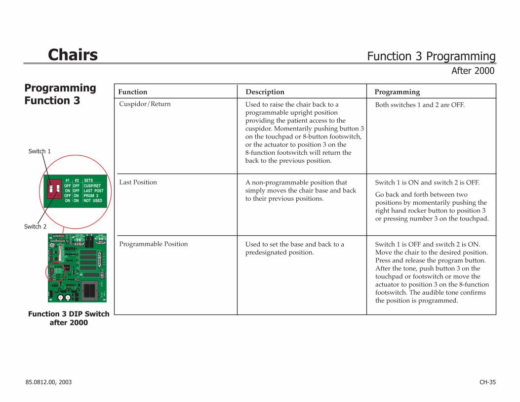
ProgrammingFunction 3
Function Programming
Cuspidor/Return
Last Position
Programmable Position
Description
Both switches 1 and 2 are OFF.
Switch 1 is ON and switch 2 is OFF.
Go back and forth between two positions by momentarily pushing theright hand rocker button to position 3or pressing number 3 on the touchpad.
Switch 1 is OFF and switch 2 is ON.Move the chair to the desired position.Press and release the program button.After the tone, push button 3 on thetouchpad or footswitch or move theactuator to position 3 on the 8-functionfootswitch. The audible tone confirmsthe position is programmed.
Used to raise the chair back to a programmable upright position providing the patient access to the cuspidor. Momentarily pushing button 3on the touchpad or 8-button footswitch,or the actuator to position 3 on the 8-function footswitch will return theback to the previous position.
A non-programmable position that simply moves the chair base and back to their previous positions.
Used to set the base and back to a predesignated position.
After 2000

85.0812.00, 2003 CH-36
Chairs Cascade 1040 Vac Back Floor Box with Utilities
Air
Water
Water shutoff valve
Circulatingsyringe driptube
NOTE: Ribbed tubing is connected to pilot air
To/from vac back assistant’s instrumentation
Item # Part Number Description
1. 33.0048.04 Valve, toggle, 3-way, ON/OFF
2. 24.0100.03 Pressure indicator
2
1
85.0812.00, 2003 CH-37
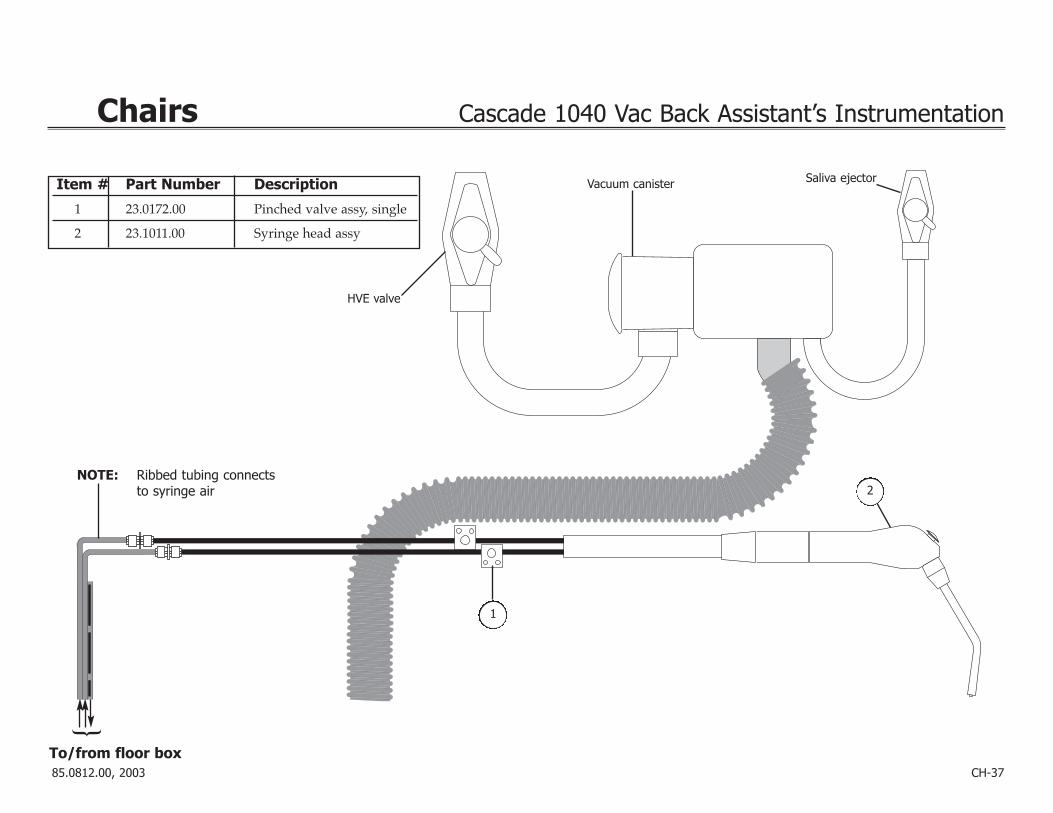
Chairs Cascade 1040 Vac Back Assistant’s Instrumentation
HVE valve
Vacuum canister Saliva ejector
NOTE: Ribbed tubing connectsto syringe air
To/from floor box
2
1
Item # Part Number Description
1 23.0172.00 Pinched valve assy, single
2 23.1011.00 Syringe head assy

85.0812.00, 2003 CH-38
Chairs Water Shutoff Valve and 3-way Toggle Valve
Item # Part Number Description
1 24.0137.01 9-hole gasket, pkg 10
2 013.032.00 Spring, conc, comp, .260/.350 OD
3 24.0132.00 Piston with O-ring, Delrin
4 24.0440.02 Diaphragm, pkg 10
Item # Part Number Description
1 33.0031.01 Toggle with pin, Gray
2 29.0840.00 Stem with O-rings, 3-way
3 22.0040.00 Spring, comp., .300 OD x .40
1
23
4
1
2
3
Water Shutoff Valve34.0031.00
3-Way Toggle Valve33.0048.04

85.0812.00, 2003 CH-39
Chairs Glide Bar Tension Block and Swivel Brake
Item # Part Number Description
1 61.1569.00 Wearpad, sliding wedge
Cascade 1040 Glide Bar Tension Block
Decade 1011/1021 Glide Bar Tension Block
Cascade 1040 Swivel Brake61.2055.00
Item # Part Number Description
1 61.1569.00 Wearpad, sliding wedge
Item # Part Number Description
1 61.1228.00 Thrust washer-brake pad assy
2 61.2227.00 Nut-brake pad assy
Decade 1011/1021 Swivel Brake61.1538.01
Item # Part Number Description
1 61.1537.01 Replacement brake pads
2
1
1
1
1

85.0812.00, 2003 CH-40
Chairs Double-Articulating Headrest
Adjusting theDouble-ArticulatingHeadrest
Adjust Cascade 1040 Headrest Glide Bar Tension
Double-Articulating Headrest61.2265.00
Item # Part Number Description
1 61.2116.XX Double articulating headrest upholstery
— 61.3046.00 Conversion kit, 1040 screw-on headrest cushion. Applies to chairs with the wire formed headrest cushion (S/N E442969 and before).
1
UpholsteryReplacement
Follow these steps to adjust the headrest.
Task Description
1 Adjust the glide bar until the headrest moves freely yetmaintains its position.
2 Turn the screw clockwise to increase friction and holdthe headrest more securely.
3 Turn the screw counterclockwise to decrease friction and allow the headrest to move up and downmore freely. The Decade chair adjustment screw is located in back of the glide bar.NOTE: Use a phillips head screwdriver to adjust the glide
bar tension. You may need to remove the backupholstery to access the adjustment screw.

85.0812.00, 2003 CH-41
Chairs
Problem Action
Chair is inoperative 1 Do any relays on the printed circuit board click? Refer to Testing Relay Click.YES: Go to step 2.NO: Go to step 3.
2 Is the base/back all the way down?YES: Go to Base or Back Up Function is Inoperative.NO: Go to step 3.
3 Has the solenoid fuse blown (120V only)?YES: Replace the fuse. Check for shorted solenoids or shorted wiring to the solenoids (refer to
Testing Solenoid Continuity and Testing Wiring Harness Continuity). Retest chair functions.NO: Go to step 4.
4 Complete the steps outlined in Testing Magnetic Pull. Is there magnetic pull at each solenoid?YES: Go to step 5.NO: Remove and replace the faulty solenoid (refer to Removing a Solenoid and
Replacing a Solenoid). Retest chair functions.
5 Is the chair in hydrostatic lock?YES: Remedy hydrostatic lock (refer to Correcting Hydrostatic Lock). Retest chair functions.NO: Check for and replace a faulty manifold or valve.
TroubleshootingPCBs with no LEDs
Diagnostic information is presented in the following charts.

85.0812.00, 2003 CH-42
Chairs Troubleshooting (for PCB with no LEDs)
Problem Action
6 Is the printed circuit board fuse(s) blown?YES: Remove and replace the fuse, then check the potentiometer wiring for damage, shorts, or
improper wiring. If the fuse blows again, disconnect the potentiometer wiring at P4 and P5 on the printed circuit board. If the fuse still blows, remove and replace the printed circuit board. Otherwise remove and replace the potentiometer wiring.
NO: Check the condition of the stop plate limit switches and wiring. Check the printedcircuit board connector P6 (limit switches). Unplug the chair from its power outlet and plug it in again. If the chair is still inoperative, make sure there is power at the outlet. If the preceding steps do not solve the problem, go to step 7.
7 Disconnect the footswitch and, if installed, the touchpad. Use the printed circuit board test points toactivate chair up functions (refer to Using Chair Test Points). Does the chair work now?YES: If there is a footswitch only, remove and replace the footswitch. If there is a touchpad
only, remove and replace the touchpad. If there is both a footswitch and touchpad, go to step 8.
NO: The printed circuit board is faulty, remove and replace the printed circuit board.
8 Reconnect the footswitch to the printed circuit board. Using the footswitch, operate the chair. Doesthe chair work properly?YES: Remove and replace the touchpad.NO: Go to step 9.
9 Reconnect the touchpad to the printed circuit board. Using the touchpad, operate the chair. Does thechair work properly?YES: Remove and replace the footswitch.NO: The printed circuit board is faulty, remove and replace the printed circuit board.
Chair is inoperative
Problem Action
85.0812.00, 2003 CH-43
Chairs Troubleshooting (for PCB with no LEDs)
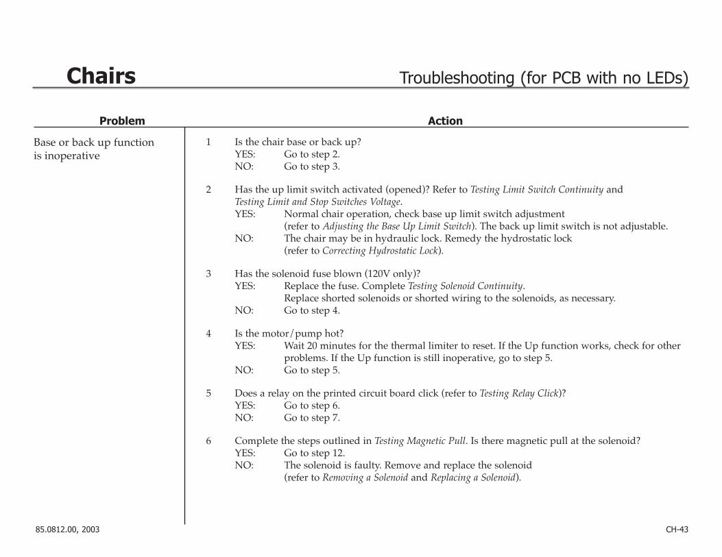
1 Is the chair base or back up?YES: Go to step 2.NO: Go to step 3.
2 Has the up limit switch activated (opened)? Refer to Testing Limit Switch Continuity and Testing Limit and Stop Switches Voltage.YES: Normal chair operation, check base up limit switch adjustment
(refer to Adjusting the Base Up Limit Switch). The back up limit switch is not adjustable.NO: The chair may be in hydraulic lock. Remedy the hydrostatic lock
(refer to Correcting Hydrostatic Lock).
3 Has the solenoid fuse blown (120V only)?YES: Replace the fuse. Complete Testing Solenoid Continuity.
Replace shorted solenoids or shorted wiring to the solenoids, as necessary.NO: Go to step 4.
4 Is the motor/pump hot?YES: Wait 20 minutes for the thermal limiter to reset. If the Up function works, check for other
problems. If the Up function is still inoperative, go to step 5.NO: Go to step 5.
5 Does a relay on the printed circuit board click (refer to Testing Relay Click)?YES: Go to step 6.NO: Go to step 7.
6 Complete the steps outlined in Testing Magnetic Pull. Is there magnetic pull at the solenoid?YES: Go to step 12.NO: The solenoid is faulty. Remove and replace the solenoid
(refer to Removing a Solenoid and Replacing a Solenoid).
Base or back up function is inoperative

Problem Action
Base or back up function is inoperative
85.0812.00, 2003 CH-44
Chairs Troubleshooting (for PCB with no LEDs)
7 Disconnect the footswitch and, if installed, the touchpad. Use the printed circuit board test points toactivate chair up function (refer to Using Chair Test Points). Does a relay on the printed circuit boardclick (refer to Testing Relay Click)?YES: Go to step 8.NO: Go to step 10.
8 Does the UP function work?YES: If there is a footswitch only, remove and replace the footswitch. If there is a touchpad
only, remove and replace the touchpad. If there is both a footswitch and touchpad, go to step 9.
NO: Go to step 11.
9 Reconnect the footswitch to the printed circuit board. Using the footswitch, operate the chair. Doesthe UP function work?YES: Remove and replace the touchpad.NO: Go to step 10.
10 Reconnect the touchpad to the printed circuit board. Using the touchpad, operate the chair. Does theUP function work?YES: Remove and replace the footswitch.NO: Go to step 11.
11 Complete the steps for Testing Magnetic Pull. Is there magnetic pull at the solenoid? YES: Go to step 14.NO: Remove and replace the faulty solenoid(s) (refer to Removing a Solenoid and
Replacing a Solenoid).

Problem Action
85.0812.00, 2003 CH-45
Chairs Troubleshooting (for PCB with no LEDs)
Base or back up function is inoperative
12 Is the limit switch faulty or open (refer to Testing Limit Switch Continuity and Testing Limit and Stop Switches Voltage)?YES: Adjust or remove and replace the limit switch. Adjust the base up limit switch
(refer to Adjusting the Base Up Limit Switch).NO: Go to step 13.
13 Is the limit switch wiring faulty (refer to Testing Wiring Harness Continuity)?YES: Repair or replace the limit switch wiring.NO: Unplug the chair and plug it back in. If the problem remains, the printed circuit board is
faulty, replace the printed circuit board.
14 Is there an open in the limit switch wiring (refer to Testing Wiring Harness Continuity)?YES: Repair or replace the wiring.NO: Go to step 15.
15 Is the base up limit switch out of adjustment?YES: Adjust the limit switch (refer to Adjusting the Base Up Limit Switch). The back up limit
switch is not adjustable.NO: Go to step 16.
16 Is there noise from the motor/pump?YES: Go to step 17.NO: Go to step 18.

85.0812.00, 2003 CH-46
Chairs Troubleshooting (for PCB with no LEDs)
Problem Action
Base or back up function is inoperative
Base or back down function is inoperative
17 Is the motor current more than 5 Amps (refer to Testing the Motor/Pump)?YES: The motor/pump is faulty. Remove and replace the motor/pump.NO: Remove and replace the motor/pump capacitor. Test the Up function. If it still does not
work,the manifold is faulty. Remove and replace it.
18 Is there an open or short in the motor/capacitor wiring (refer to Testing Wiring Harness Continuity)?YES: Contact an A-dec customer service representative for proper repair procedures of the
motor/pump capacitor wiring.NO: The printed circuit board is faulty, remove and replace the printed circuit board.
1 Try an Up function first, then a Down function. Is the base or back still up?YES: Go to step 2.NO: Go to step 3.
2 Has the limit switch activated (opened) (refer to Testing Limit Switch Continuity and Testing Limit and Stop Switches Voltage)?YES: Go to step 3.NO: The chair may be in hydrostatic lock. Remedy hydrostatic lock
(refer to Correcting Hydrostatic Lock). Retest chair functions.
3 Does a relay on the printed circuit board click (refer to Testing Relay Click)?YES: Go to step 7.NO: Go to step 4.

85.0812.00, 2003 CH-47
Chair Troubleshooting (for PCB with no LEDs)
Problem Action
Base or back down function is inoperative
4 Disconnect the footswitch and, if installed, the touchpad. Use the printed circuit board test points toactivate chair down functions (refer to Using Chair Test Points). Does the down function work?YES: If there is a footswitch only, remove and replace the footswitch. If there is a touchpad
only, remove and replace the touchpad. If there is both a footswitch and touchpad, go to step 5.
NO: Check condition of stop and/or cuspidor limit switches and wiring (refer to Testing Limit and Stop Switches Voltage, Testing Limit Switch Continuity, and Testing Wiring Harness Continuity). Check the printed circuit board connector P6 (limit switches). Unplug the chair and plug it back in. If the problem remains, the printed circuit board is faulty. Replace the printed circuit board.
5 Reconnect the footswitch to the printed circuit board. Using the footswitch, operate the chair. Doesthe chair down function work?YES: Remove and replace the touchpad.NO: Go to step 6.
6 Reconnect the touchpad to the printed circuit board. Using the touchpad, operate the chair. Does thechair down function work?YES: Remove and replace the footswitch.NO: Check condition of stop switch and/or cuspidor limit switch and wiring (refer to Testing
Limit and Stop Switches Voltage, Testing Limit Switch Continuity, and Testing Wiring Harness Continuity). Check the printed circuit board connector P6 (limit switches). Unplug the chair and plug it back in. If the problem remains, the printed circuit board is faulty. Replace the printed circuit board.
7 Complete the steps for Testing Magnetic Pull. Is there magnetic pull at each solenoid?YES: Replace faulty manifold/valve.NO: Go to step 8.
8 Has the solenoid fuse blown (120V only)?YES: Replace the fuse. Complete the steps for Testing Solenoid Continuity. Replace shorted
solenoids or shorted wiring to the solenoids as necessary.NO: Replace the faulty solenoid.

85.0812.00, 2003 CH-48
Chairs Troubleshooting (for PCB with no LEDs)
Problem Action
Back moves for base only function or base moves forback only function
Only chair function is base up
1 Disconnect the footswitch and, if installed, the touchpad. Use the printed circuit board test points toactivate chair functions (refer to Using the Chair Test Points). Does the chair work properly now?YES: If there is a footswitch only, remove and replace the footswitch. If there is a touchpad
only, remove and replace the touchpad. If there is both a footswitch and touchpad, go to step 2.
NO: The printed circuit board is faulty. Replace the printed circuit board.
2 Reconnect the footswitch to the printed circuit board. Using the footswitch, operate the chair. Doesthe chair work properly?YES: Remove and replace the touchpad.NO: Go to step 3.
3 Reconnect the touchpad to the printed circuit board. Using the touchpad, operate the chair. Does thechair work properly?YES: Remove and replace the footswitch.NO: The printed circuit board is faulty. Remove and replace the printed circuit board.
1 Are the stop plate limit switches activated?YES: Go to step 2.NO: Go to step 3.
2 Is the stop plate stuck?YES: Remove obstruction from the stop plate.NO: Go to step 3.
3 Check the connections and the limit switches (refer to Testing Limit and Stop Switches Voltage, TestingLimit Switch Continuity, and Testing Wiring Harness Continuity). Are wire connections or limits switches faulty?YES: Repair or replace components, as necessary.NO: Go to step 4.

85.0812.00, 2003 CH-49
Chairs Troubleshooting (for PCB with no LEDs)
Problem Action
Only chair function is base up
Unable to program auto-positioning
4 If there is a cuspidor, check for proper activation of the limit switch when gently lifting up on the cuspidor bowl. Is there a clicking sound?YES: Go to step 5.NO: Replace the switch (refer to Post Boxes and Cuspidors (PB) for the part number).
5 Disconnect the 2-pin connector at P14 on the printed circuit board. Gently short across P14 with asmall flat-blade screwdriver. Does the chair operate correctly?YES: Replace the cuspidor cable (P/N 41.1148.00).NO: Replace the printed circuit board.
1 Review auto-positioning procedures (refer to Programming the Chair). Does the chair move when youtry to program it?YES: Check for shorted wires at footswitch connector P2, and at touchpad connector P1, if
installed, on the printed circuit board (refer to Testing Wiring Harness Continuity).NO: Go to step 2.
2 Does the chair move to the wrong position?YES: Go to Incomplete auto-positioning cycle.NO: Go to step 3.
3 Disconnect the footswitch and, if installed, the touchpad. Use the printed circuit board test points to program the chair (refer to Using Chair Test Points). Did the chair program satisfactorily?YES: If there is a footswitch only, remove and replace the footswitch. If there is a touchpad
only, remove and replace the touchpad. If there are both a footswitch and touchpad, go to step 7.
NO: Go to step 6.
4 Reconnect the footswitch to the printed circuit board. Using the footswitch, program the chair. Didthe chair program satisfactorily?YES: Remove and replace the touchpad.NO: Go to step 5.

85.0812.00, 2003 CH-50
Chairs Troubleshooting (for PCB with no LEDs)
Problem Action
Unable to program auto-positioning
Unable to program auto-positioning for the touchpad and footswitch
5 Reconnect the touchpad to the printed circuit board. Using the touchpad, program the chair. Did thechair program satisfactorily?YES: Remove and replace the footswitch.NO: Go to step 6.
6 Is there an open or short in the positioning potentiometer wiring (refer to Testing Wiring Harness Continuity)?YES: Repair positioning potentiometer wiring.NO: Go to step 7.
7 Are there any poor or reversed potentiometer connections (refer to Testing Positioning Potentiometer Voltage)?YES: Repair positioning potentiometer connections.NO: The printed circuit board is faulty. Replace the printed circuit board.
1 Disconnect the footswitch and try to operate the automatic functions from the touchpad. Does the touchpad work properly?YES: Replace the footswitch.NO: Go to step 2.
2 Plug the footswitch back in and disconnect the touchpad. Try to operate the automatic functionsfrom the foot control. Does the footswitch work properly? YES: Replace the touchpad.NO: Call your A-dec customer service representative for assistance.

85.0812.00, 2003 CH-51
Chairs Troubleshooting (for PCB with no LEDs)
Problem Action
Incomplete auto-positioning cycle
1 Has a new printed circuit board been installed?YES: Reprogram the chair printed circuit board.NO: Go to step 2.
2 Has a new potentiometer been installed?YES: Verify that the positioning potentiometer has been installed correctly and that positions
have been properly programmed.NO: Go to step 3.
3 Does base or back travel time exceed 40–45 seconds?YES: Adjust the manifold speed control valves (refer to Adjusting the Hydraulic Manifold).NO: Go to step 4.
4 Is the back stopping short of full upright?YES: Positioning potentiometer is defective or in deadband. Adjust the potentiometer
(refer to Adjusting the Base Positioning Potentiometer).NO: Go to step 5.
5 Does the base or back only go in one direction?YES: Check for faulty positioning potentiometers, wiring, and connections.NO: Go to step 6.
6 Does the base or back go in the wrong direction?YES: Go to step 7.NO: Go to step 8.
7 Is the potentiometer mechanical drive slipping?YES: Tighten the gear setscrew, or replace the connecting tubing, and then adjust the
potentiometer (refer to Adjusting the Base Positioning Potentiometer).NO: Go to step 8.

85.0812.00, 2003 CH-52
Chairs Troubleshooting (for PCB with no LEDs)
Problem Action
Incomplete auto-positioning cycle
8 Does the base or back shut off at the same time?YES: The printed circuit board is faulty. Replace the printed circuit board.NO: Go to step 9.
9 Is the potentiometer resistance 0–5K ± 20% ohm (Ω)? Refer to Testing Positioning PotentiometerContinuity, Testing Wiring Harness Continuity, and Testing Base and Back Positioning Potentiometer Voltage.YES: Go to step 10.NO: Positioning potentiometer is faulty. Replace the potentiometer.
10 Are the potentiometer wiring and connections equal to 0Ω (refer to Testing Positioning PotentiometerContinuity, Testing Wiring Harness Continuity and Testing Base and Back Positioning Potentiometer Voltage)?YES: Go to step 11.NO: Repair or replace the wiring and connections.
11 Is the potentiometer mechanical drive slipping?YES: Tighten the gear setscrew, or replace the connecting tubing, and then adjust
the potentiometer.NO: Go to step 12.
12 Are the potentiometers turning?YES: The printed circuit board is faulty. Replace the printed circuit board.NO: Check for a loose or damaged potentiometer mount or improper adjustment
(refer to Adjusting the Base Positioning Potentiometer and Adjusting the Base Up Limit Switch).

85.0812.00, 2003 CH-53
Chairs Troubleshooting (for PCB with no LEDs)
Problem Action
Auto-positioning function is inoperative
1 Reprogram the chair auto-positioning settings (refer to Programming the Chair). Does the chair go tothe wrong position?YES: Go to Incomplete auto-positioning cycle.NO: Go to step 2.
2 Disconnect the footswitch and, if installed, the touchpad. Use the printed circuit board test points toactivate chair auto functions (refer to Using Chair Test Points). Does the chair function properly?YES: If there is a footswitch only, remove and replace the footswitch. If there is a touchpad
only, remove and replace the touchpad. If there is both a footswitch and touchpad, go to step 3.
NO: Unplug the chair and plug it back in. If the problem remains, the printed circuit boardis faulty. Replace the printed circuit board
3 Reconnect the footswitch to the printed circuit board. Using the footswitch, operate the chair. Doesthe chair work properly now?YES: Remove and replace the touchpad.NO: Go to step 4.
4 Reconnect the touchpad to the printed circuit board. Using the touchpad, operate the chair. Does thechair work properly now?YES: Remove and replace the footswitch.NO: Unplug the chair and plug it back in. If the problem remains, the printed circuit board is
faulty, remove and replace the printed circuit board.

85.0812.00, 2003 CH-54
Chairs Troubleshooting (for PCB with no LEDs)
Problem Action
Auto-positioning for one or more functions is inoperative on a unit withboth a footswitch and a touchpad
1 Unplug the footswitch and try to operate the automatic functions from the touchpad. Does thetouchpad work properly?YES: Replace the footswitch.NO: Go to step 2.
2 Plug the footswitch back in and disconnect the touchpad. Try to operate the automatic functionsfrom the foot control. Does the footswitch work properly? YES: Replace the touchpad.NO: The printed circuit board is faulty. Replace the printed circuit board.

85.0812.00, 2003 CH-55
Chairs Test Procedures
Using Chair Test Points • The chair test points are used to test chair function without a footswitch connected to the printed
circuit board.
• To access the test points, you must remove the motor/pump housing and the circuit board cover.
• Short the test points next to the function you wish to test.
NOTE: New style test positions ENTR = Position 0 (Red)EXIT = Position 2 (Green)
NOTE: Old style test positionsENT = Position 0EX = Position 2
WARNING
Hazardous AC voltagesare present on theprinted circuit board. Donot touch any part onthe printed circuit boardexcept the test points. P
2
SW
1
TESTPOINTSENTREXITBS DNBS UPBK DNBK UP
P1
NOTE: Connector P1 omitted for clarity.
Before June 2000
85.0812.00, 2003 CH-56
Chairs Test Procedures
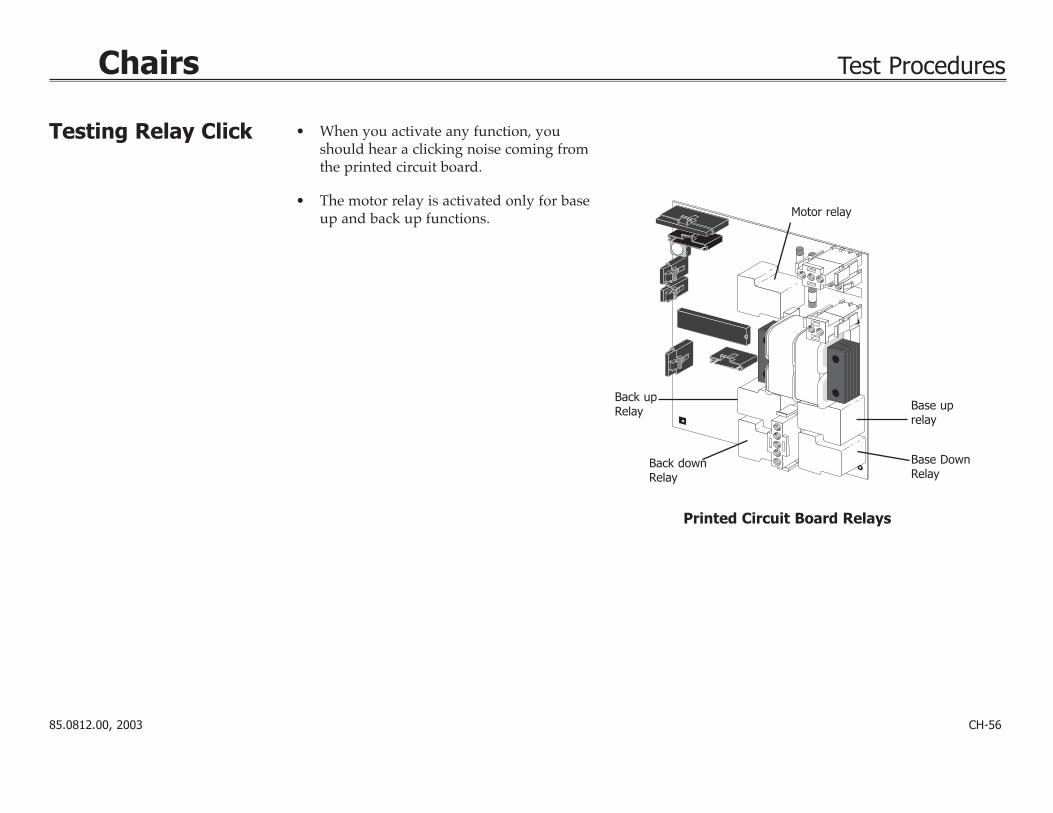
Testing Relay Click • When you activate any function, youshould hear a clicking noise coming fromthe printed circuit board.
• The motor relay is activated only for baseup and back up functions. Motor relay
Back downRelay
Back upRelay Base up
relay
Base DownRelay
Printed Circuit Board Relays

85.0812.00, 2003
Chairs Test Procedures
Testing theMotor/Pump
Testing Magnetic Pull
White wire
Red wire
Motor/pump
Motor/pumpcapacitor
Motor/Pump Test
Back upsolenoid
Hydraulicmanifold
Base downsolenoidBase up
solenoid
Magnetic Pull Test
Back downsolenoid (hidden)
CH-57
NOTE: This test requires the use of a currentpickup probe.
• Clip the probe onto the red wire going tothe motor/pump.
• Activate a base up or back up function.
Result: You should read 5 Amps (maximum) of current for 120V motor/pump.
You should read 2.5 Amps (maximum) of currentfor 240V motor/pump.
• While holding the tip of screwdrivernear a solenoid, activate the appropriatechair function.
Result: You should feel the tug of the magnetic field generated around the solenoid.

85.0812.00, 2003 CH-58
Chairs Test Procedures
Testing Power Cord Continuity
WARNING
Hazardous AC voltagesare present on the printed circuit board.Make sure power hasbeen removed from thechair before proceeding.Failure to remove powerfrom the chair may resultin serious injury fromelectrical shock.
Follow these steps to test power cord continuity.
Task Description
1 Disconnect the power cord (J1) from thechair printed circuit board.
2 Touch a volt-ohmmeter (VOM) probe to pin 1 of J1 and the other probe to first oneand then the other blade of the power plug.
Result: One blade should read 1/2 ohm or less, the other blade should read infinite (∞) resistance.
If both blades read infinite (∞) resistance, the power cord is defective and must be replaced.
3 Touch a VOM probe to pin 3 of J1 andrepeat the second step.
4 Touch a VOM probe to pin 2 or J1 and theother probe to ground on the plug.
Result: The resistance should be 1/2 ohm or less.
Pin 3
Pin 2
Pin 1
Pin 1marker
J1
GroundJ1
Power Cord Continuity Test

85.0812.00, 2003 CH-59
Chairs Test Procedures
Testing LimitSwitch Continuity
WARNING
Hazardous AC voltagesare present on the printed circuit board.Make sure power hasbeen removed from thechair before proceeding.Failure to remove powerfrom the chair may resultin serious injury fromelectrical shock.
Follow these steps to test limit switch continuity.
Task Description
1 Disconnect the wiring harness from the limitswitch. It is not necessary to remove the limit switch.
2 Touch a volt-ohmmeter (VOM) probe to thecommon terminal and the other probe to thenormally open terminal and then to the normally closed terminal.
Result: The normally closed terminal should give a reading of 1/2 ohm (Ω) or less.
The normally open terminal should read infinite (∞)resistance.
If both terminals indicate infinite (∞) resistance or indicate 1/2 ohm (Ω) or less, the switch is defective and must be replaced.
NOTE: If you are replacing a base up limit switch,adjust the switch after replacement (refer toAdjusting the Base Up Limit Switch).
Normally open
Limit Switch Continuity Test
Normally closed Switch arm
Common terminal
85.0812.00, 2003 CH-60
Chairs Test Procedures
Testing PositioningPotentiometerContinuity
NOTE: If you are replacing a positioning potentiometer,refer to Adjusting theBase PositioningPotentiometer andAdjusting the Base UpLimit Switch.
WARNING
Hazardous AC voltagesare present on the printed circuit board.Make sure power hasbeen removed from thechair before proceeding.Failure to remove powerfrom the chair may resultin serious injury fromelectrical shock.
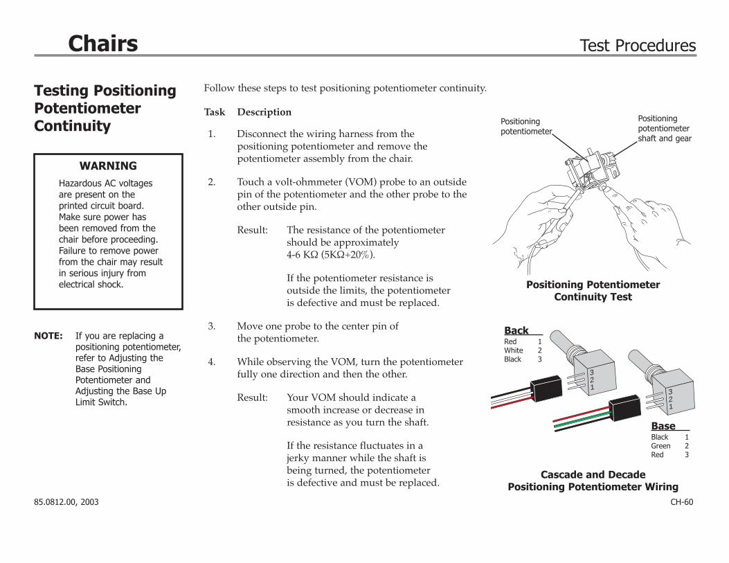
Task Description
1. Disconnect the wiring harness from the positioning potentiometer and remove the potentiometer assembly from the chair.
2. Touch a volt-ohmmeter (VOM) probe to an outsidepin of the potentiometer and the other probe to theother outside pin.
Result: The resistance of the potentiometer should be approximately 4-6 KΩ (5KΩ+20%).
If the potentiometer resistance is outside the limits, the potentiometeris defective and must be replaced.
3. Move one probe to the center pin of the potentiometer.
4. While observing the VOM, turn the potentiometerfully one direction and then the other.
Result: Your VOM should indicate a smooth increase or decrease in resistance as you turn the shaft.
If the resistance fluctuates in a jerky manner while the shaft is being turned, the potentiometer is defective and must be replaced.
Positioningpotentiometer
Positioningpotentiometershaft and gear
Positioning Potentiometer Continuity Test
321
321
BaseBlack 1Green 2Red 3
BackRed 1White 2Black 3
Cascade and Decade Positioning Potentiometer Wiring
Follow these steps to test positioning potentiometer continuity.

85.0812.00, 2003 CH-61
Chairs Test Procedures
Testing WiringHarness Continuity
WARNING
Hazardous AC voltagesare present on the printed circuit board.Make sure power hasbeen removed from thechair before proceeding.Failure to remove powerfrom the chair mayresult in serious injuryfrom electrical shock.
Follow these steps to test wiring harness continuity.
Task Descriptions
1 Disconnect the wiring harness from thelimit switch or positioning potentiometer and the printed circuit board. Do not removefrom chair.
2 Touch a volt-ohmmeter (VOM) probe to pin 1at one end of the harness and the other probe to pin 1 at the other end of the harness.
Result: The VOM should read 1/2 ohm (Ω) or less. If the VOM indicates (∞) or fluctuating resistance, the harness is defectiveand must be replace.
3 Repeat the steps for each wire in the harness.
Positioning Potentiometer Continuity Test
Pin 1Pin 1
Pin 2
Pin 2
CH-62
Chairs Test Procedures
Testing SolenoidContinuity
WARNING
Hazardous AC voltagesare present on the printed circuit board.Make sure power hasbeen removed from thechair before proceeding.Failure to remove powerfrom the chair mayresult in serious injuryfrom electrical shock.
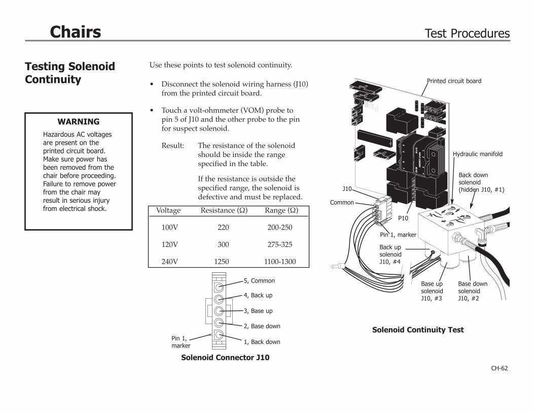
Use these points to test solenoid continuity.
• Disconnect the solenoid wiring harness (J10)from the printed circuit board.
• Touch a volt-ohmmeter (VOM) probe to pin 5 of J10 and the other probe to the pin for suspect solenoid.
Result: The resistance of the solenoidshould be inside the range specified in the table.
If the resistance is outside the specified range, the solenoid is defective and must be replaced.
Solenoid Connector J10
Voltage Resistance (Ω) Range (Ω)
100V 220 200-250
120V 300 275-325
240V 1250 1100-1300
5, Common
Pin 1,marker
4, Back up
3, Base up
2, Base down
1, Back down
P2
SW
1
TE
ST
PO
INT
SBK UP BK DN BS UP
EXDN
ENT
INP
UT
115/230VIN
PU
T 115/230V
12
34
56
87
S P
WS
P W
60 HZ
60 HZ
P1
Printed circuit board
Hydraulic manifold
Back down solenoid(hidden J10, #1)
Base up solenoidJ10, #3
Back up solenoidJ10, #4
Pin 1, marker
Common
J10
P10
Base down solenoidJ10, #2
Solenoid Continuity Test

85.0812.00, 2003 CH-63
Chairs Test Procedures
Testing Base andBack PositioningPotentiometerVoltage
Testing Limit andStop SwitchesVoltage
WARNING
Hazardous AC voltagesare present on the printed circuit board.Make sure power hasbeen removed from thechair before proceeding.Failure to remove powerfrom the chair mayresult in serious injuryfrom electrical shock.
• Touch the black probe of the volt-ohmmeter(VOM) to the top pin of the potentiometerand the red probe to the lower pin.
Result: The voltage available should be approximately 5V (+1V).
If the voltage is zero, the positioning potentiometer wiring harness or the chair printed circuitboard should be replaced.
Positioning Potentiometer Voltage Test
PositioningPotentiometer
• Disconnect the connector from the switch. Be sure to pull on the connector and not the wiring.
• Touch a volt-ohmmeter (VOM) probe to onepin of the connector and the other to theremaining pin.
Result: The voltage available should be 5V (+1V) for PCBs with no LEDs,12V (+1V) for PCBs with LEDs.
If the voltage is zero, the switch wiring harness or the chair printed circuit board must be replaced. Limit and Stop Switches Voltage Test

85.0812.00, 2003 CH-64
Chairs Notes


![Final project Math 1040 - Maria Davilamariadavila.weebly.com/.../math1040final_project_recovered.pdf · Final project Math 1040 [FINAL PROJECT MATH 1040] April 30, 2014 2 ... Conclusion.](https://static.fdocuments.in/doc/165x107/5aa1ba647f8b9a80378c059e/final-project-math-1040-maria-project-math-1040-final-project-math-1040-april.jpg)