Ch8 Inverters (converting DC to AC) 8-1 Introduction ․ Converting DC to AC ․ Applications:...
42
Ch8 Inverters (converting DC to AC) 8-1 Introduction ․Converting DC to AC ․Applications: adjustable-speed AC motor drives. Uninterruptible power supply (UPS). AC appliances run from an automobile battery.
-
Upload
reilly-lusher -
Category
Documents
-
view
227 -
download
0
Transcript of Ch8 Inverters (converting DC to AC) 8-1 Introduction ․ Converting DC to AC ․ Applications:...

Ch8 Inverters (converting DC to AC)
8-1 Introduction
․Converting DC to AC․Applications: adjustable-speed AC motor drives. Uninterruptible power supply (UPS).
AC appliances run from an automobile battery.

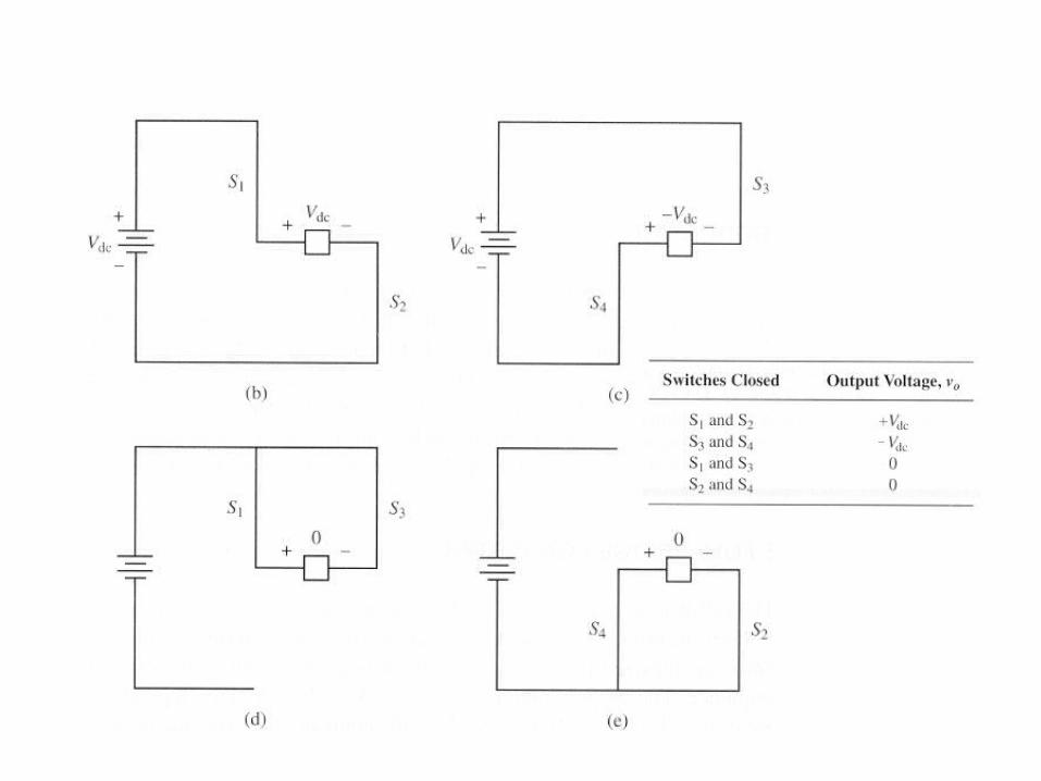
8-2 The full-bridge converter Fig 8-1 :
S1 and S4 should not be closed at the same time, nor should S2 and S3, otherwise, a short circuit would exist across the dc source

8-3 The square-wave Inverter Fig 8-2. (Waveform)
An inductive load presents some considerations in designing the switches in full – bridge circuit because the switch current must be bidirectional.
TtT
,BeR
Vdc
Tt,Ae
R
Vdc
tititi
Tt
t
nfo
2
20
2
:ti f forced current
:tin natural current R
L


In steady – state.
R
VdcinA
axBeR
VdcTi
inAeR
Vdcoi
oo
oo
Im
Im2
Im
RVdcaxB Im
TtT
,eR
VdcaxIm
R
Vdc
Tt,eR
VdcminI
R
Vdc
ti Tt
t
o
2
20
2
By symmetry , Imax= - Imin =
2
Tio
2
T
eR
VdcinIm
R
dcV
2
2
1
1T
T
e
e
R
VdcinImaxIm

rms load current :
IsVdcP
ceresisloadRRrmsIP
dteR
Vdcin
R
Vdc
Tdtti
TIrms
dc
L
TtT
o
tan
Im21
2
2
2
00
2
If the switches are ideal , then Ldc PP.
.

Fig 8-3 Full – bridge inverter using BJTs

8-4 Fourier Series Analysis
With no dc component in the output
RIPP
)I
(IIrms
tnwsinIti
tnwsinVtv
rms,nn
nn
n
n
nrms,n
nonn
o
nonn
2
11
2
11
2
1
10
2
.
:
nharmonic
atimpedanceloadZ
Z
VI
n
n
nn
In square wave output
tnwn
Vdctv o
oddno sin
4

8-5 Total harmonic distortion (THD)
A quality of the AC output voltage or current. Assuming no dc component in the output
?THD
.V
VV
V
V
THD
I
rms,
rms,rms
rms,
rms,nn
V
1
21
2
1
2
2

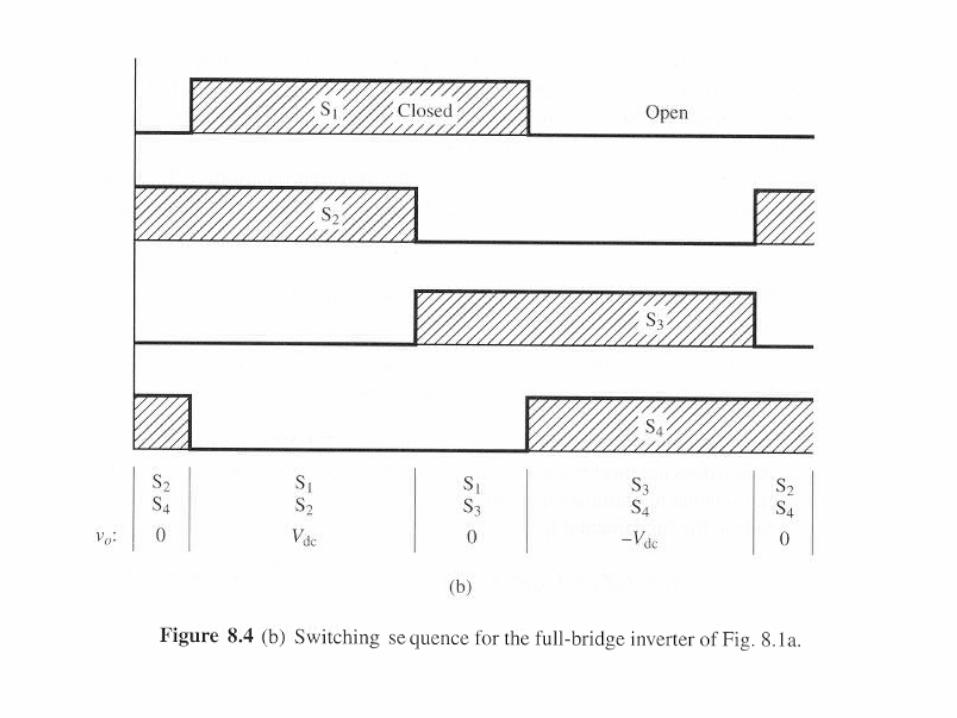
8-7 Amplitude and harmonic control By adjusting the interval , the output voltage can be controlled. Fig.8-4

tnwsinVtv
VdcwtdVdcrmsV
onoddn
o
2
11 2
∵Half – wave symmetry
.cos4
cos4
sin2
1
VdcV
nn
VdctwdtnwVdcV oon
Harmonic content can also be controlled by adjusting α Harmonic n is eliminated if
90n
n90

Amplitude control and harmonic reduction may not be compatible. To control both amplitude and harmonic, it is necessary to have control over the dc input voltage.
Fig 8-5 A graphical representation of the integration in the Fourier series coefficient.


8-8 The half – bridge Inverter Fig 8-7

A square-wave output or bipolar pulse-width-modulated (PWM) output.
22
Vdcor
Vdcvo
The voltage across an open switch is twice the load voltage
VdcVdc
22

8-9 pulse-width-modulated (PWM) output Advantage: Reduced filter requirements to decrease harmonics and the control of the output voltage amplitude can be realized Disadvantage: more complex control circuits for switches and increased loss
es due to more frequent switching.
Sinusoidal PWM requires:(1). a reference (modulating or control) signal-sinusoidal.(2). a carrier (triangular wave) signal that controls the switching fre.
Bipolar switching: Fig 8-8 Vdcvo
triesino
triesino
vv,Vdcv
vv,Vdcv
S1 and S2 are on when Vsine>VtriS3 and S4 are on when Vsine < Vtri


Unipolar Switching:
Vdc,,Vdcvo 0
S1 is on when Vsine>Vtri S2 is on when -Vsine<Vtri S3 is on when -Vsine>Vtri S4 is on when Vsine<Vtri
Fig 8-9One (First)
Another (second) Fig 8-10
S1 is on when Vsine>Vtri (high fre) S4 is on when Vsine<Vtri (high fre) S2 is on when Vsine> 0 (low fre)
S3 is on when Vsine< 0 (low fre)


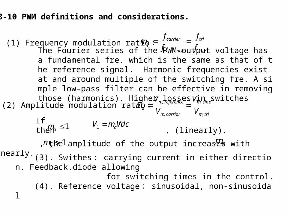
8-10 PWM definitions and considerations.
(1) Frequency modulation ratio :esin
tri
reference
carrierf f
f
f
fm
The Fourier series of the PWM output voltage has a fundamental fre. which is the same as that of the reference signal. Harmonic frequencies exist at and around multiple of the switching fre. A simple low-pass filter can be effective in removing those (harmonics). Higher losses in switches
(2) Amplitude modulation ratio :tri,m
esin,m
carrior,m
reference,ma V
V
V
Vm
If , then , (linearly).1am VdcmV a1
If , the amplitude of the output increases with ,but not linearly.
1am am
(3). Swithes: carrying current in either direction. Feedback.diode allowing for switching times in the control.
(4). Reference voltage: sinusoidal, non-sinusoidal

8-11 PWM harmonics Bipolar switching: (Fig 8-8)
If mf =odd integer, the PWM output then exhibits odd symmetry
tnwsinVtv onn
o
1
For the k-th pulse of the PWM output. (Fig 8-11)
/2.ToverpulsepV
TtwdtnwtvT
V
nnnn
Vdc
twdtnwVdctwdtnwVdcV
pnk
p
k
ooo
T
n
kkkk
oo
k
kkoo
kk
knk
:
2,sin4
)](cos2cos[cos2
sinsin2
1
2
0
1
1
,


Normalized frequency spectrum : Fig 8-12 Normalized Fourier coefficients : Table 8-3
dc
nV
V
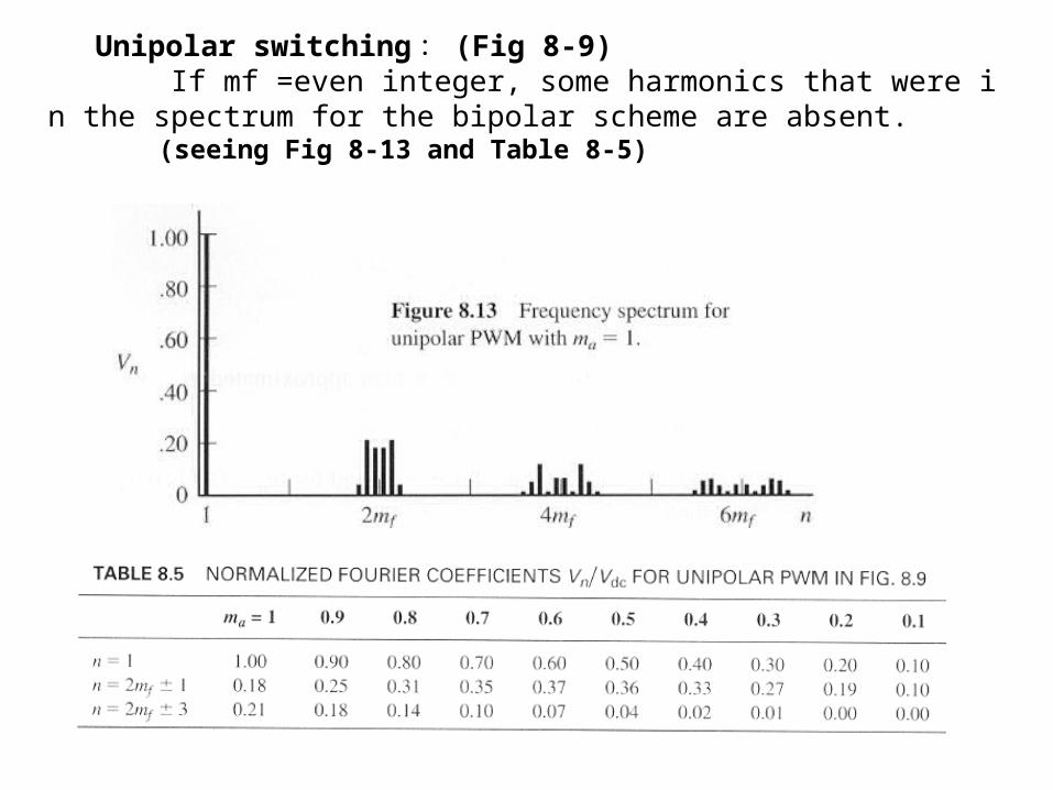
Unipolar switching: (Fig 8-9) If mf =even integer, some harmonics that were in the spectrum for the bipolar scheme are absent. (seeing Fig 8-13 and Table 8-5)

8-13 Three-phase inverters
Six-step Inverter: Fig 8-17


CABCAB v,v,v 為 Vdcor,,Vdc 0
00
00
00
ACCA
CBBC
BAAB
vvv
,vvv
,vvv
Because of the six steps in the output waveform for the line-to-neutralvoltage resulting from the six switching transitions per period.
)3(
)2(
)1(
00
00
00
NNCC
NBNB
NANA
vvv
vvv
vvv
000 CBA v,v,v 為 +Vdc or 0
(1)+(2)+(3) CoBoAoNo vvvv 3
1
)vvv( CNBNAN 0

BoAoCoNoCoCN
AoCoBoNoBoBN
CoBoAoNoAoAN
vvvvvv
vvvvvv
vvvvvv
3
1
3
23
1
3
23
1
3
2
3
2
32
3
2
6
4
ncosncosn
VdcV
ncosn
VdcV
NL,n
LL,n
Where n=1, 6k , k=1 、 2…
1
(fundamental)
(harmonics)

%31VTHD for line-to-line and line-to-neutral voltages.
ITHD is load dependent and is smaller for a R-L load.
Output fre. can be controlled by changing the switching fre..Output voltage can be controlled by adjusting the DC input voltage.
PWM three-phase Inverters Fig 8-18
S1 is on when triref,A vv
S3 is on when triref,B vv
S5 is on when triref,C vv
S2 is on when triref,C vv
S4 is on when triref,A vv
S6 is on when triref,B vv
Harmonics will be minimized if the carrier fre. is chosed to be an odd triple multiple of the reference fre. (that is 3,9,15,…times the reference).


For line-to-line voltage,
3sin
2sin
3sin
2sin
3
3
23
233
nnVB
nnVA
BAV
nn
nn
nnn
….. 三相
nk
P
kn VV
1
( 參考 P.313) …… 單相
Table 8-8 Significant amplitude coefficients
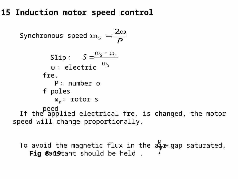
8-15 Induction motor speed control
Synchronous speed : PS
2
S1ip : S
rSS
ω : electric fre. P : number of poles ωr : rotor speed
If the applied electrical fre. is changed, the motor speed will change proportionally.
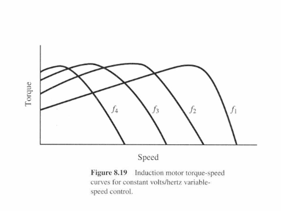
To avoid the magnetic flux in the air gap saturated, constant should be held .
f
V
Fig 8-19

The six-step inverter can be used for this application if the dc input is adjustable
Fig 8-20
If the DC source is not controllable, a DC-DC converter may be inserted between the DC source and the inverter. The PWM inverter is also another selection for this application.