Ch6 - fju.edu.t · Page 2 Wireless Communication Chapter 6 –Modulation techniques for Mobile...
43
Page 1 Chapter 6 Modulation Techniques for Mobile Radio Voltage Time Voltage Time 1 0 1 0 1 0 1 0 1 0 1 0 1 0 1 0 Wireless Communication Chapter 6 – Modulation techniques for Mobile Radio 1 Dr. Sheng-Chou Lin Modulation by Analog Inputs For example, let’ s use this analog waveform to modulate a signal. The basic, unchanging, steady radio signal without modulation is called a “ carrier” Characteristics of the carrier which we could modulate: Amplitude (i.e., strength) example: AM radio broadcasting Frequency FM broadcasting, Voice transmission in AMPS cellular Phase Modulation is the process of varying some characteristic of a radio signal in order to convey information Voltage Time Notice that frequency and phase modulation look very similar with this kind of input.
-
Upload
nguyendieu -
Category
Documents
-
view
249 -
download
4
Transcript of Ch6 - fju.edu.t · Page 2 Wireless Communication Chapter 6 –Modulation techniques for Mobile...

Page 1
Chapter 6Modulation Techniques for Mobile Radio
Voltage
Time
Voltage
Time1 0 1 0
1 0 1 0
1 0 1 0
1 0 1 0
Wireless Communication
Chapter 6 –Modulation techniques for Mobile Radio 1 Dr. Sheng-Chou Lin
Modulation by Analog Inputs
For example, let’s use this analogwaveform to modulate a signal.
The basic, unchanging, steady radiosignal without modulation is called a“carrier”Characteristics of the carrierwhich we could modulate:
Amplitude (i.e., strength)example: AM radio broadcasting
FrequencyFM broadcasting,Voice transmissionin AMPS cellular
Phase
Modulation is the process of varying some characteristic of aradio signal in order to convey informationVoltage
Time
Notice thatfrequency and
phase modulationlook very similarwith this kind of
input.

Page 2
Wireless Communication
Chapter 6 –Modulation techniques for Mobile Radio 2 Dr. Sheng-Chou Lin
Modulation and Occupied BandwidthThe bandwidth occupied by a signal depends
on:•input information bandwidth•modulation method
Information to be transmitted, called“input”or “baseband”•bandwidth usually is small, much lower
than frequency of carrier Unmodulated carrier
•the carrier itself has Zero bandwidth!! AM-modulated carrier
•Notice the upper & lower sidebands•total bandwidth = 2 x baseband
FM-modulated carrier•Many sidebands! bandwidth is a complex
mathematical function PM-modulated carrier
•Many sidebands! bandwidth is a complexmathematical function
Voltage
Time
Time-Domain(as viewed on an
Oscilloscope)
Frequency-Domain(as viewed on a
Spectrum Analyzer)
Voltage
Frequency0
fc
fc
UpperSideband
LowerSideband
fc
fc
Wireless Communication
Chapter 6 –Modulation techniques for Mobile Radio 3 Dr. Sheng-Chou Lin
Advanced Modulation ConceptsPerformance of different Modulation Types
Each type of modulation has advantages and drawbacks: Necessary bandwidth
•How wide is the signal? How much spectrum is needed?•How big a “guard band”is needed between channels?
Relative vulnerability to interference•What C/I ratio is required for good system performance?
Relative difficulty of implementation•Is complex equipment required?•Is it costly to implement?•Is it hard to maintain and adjust?
Let’s explore the different modulation methods used inmodern mobile telephony.
Page 3
Wireless Communication
Chapter 6 –Modulation techniques for Mobile Radio 4 Dr. Sheng-Chou Lin
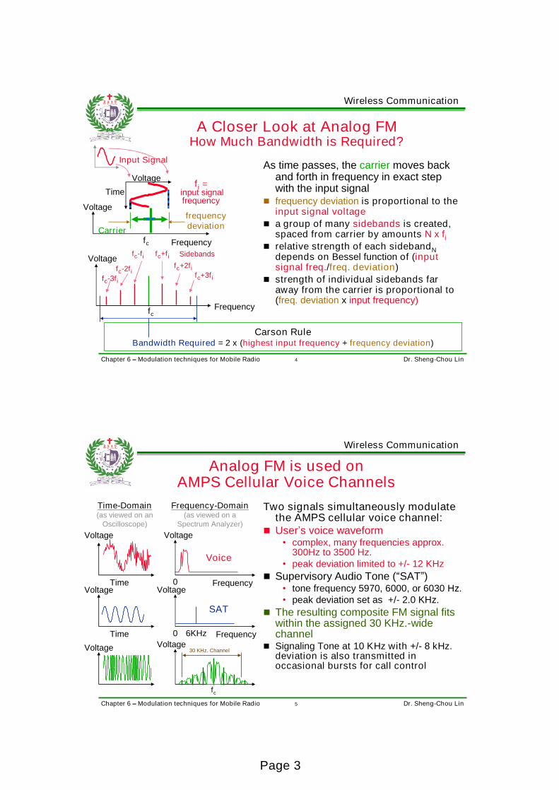
A Closer Look at Analog FMHow Much Bandwidth is Required?
Carson RuleBandwidth Required = 2 x (highest input frequency + frequency deviation)
As time passes, the carrier moves backand forth in frequency in exact stepwith the input signal
frequency deviation is proportional to theinput signal voltage
a group of many sidebands is created,spaced from carrier by amounts N x fi
relative strength of each sidebandNdepends on Bessel function of (inputsignal freq./freq. deviation)
strength of individual sidebands faraway from the carrier is proportional to(freq. deviation x input frequency)
Voltage
Frequencyfc
Sidebandsfc+fifc+2fi
fc+3fifc-3fi
fc-fi
fc-2fi
Voltage
Input Signal
fc
frequencydeviation
Voltage
Time
CarrierFrequency
fi =input signalfrequency
Wireless Communication
Chapter 6 –Modulation techniques for Mobile Radio 5 Dr. Sheng-Chou Lin
Analog FM is used onAMPS Cellular Voice Channels
Two signals simultaneously modulatethe AMPS cellular voice channel:
User’s voice waveform•complex, many frequencies approx.
300Hz to 3500 Hz.•peak deviation limited to +/- 12 KHz
Supervisory Audio Tone (“SAT”)•tone frequency 5970, 6000, or 6030 Hz.•peak deviation set as +/- 2.0 KHz.
The resulting composite FM signal fitswithin the assigned 30 KHz.-widechannel
Signaling Tone at 10 KHz with +/- 8 kHz.deviation is also transmitted inoccasional bursts for call control
VoltageTime
Time-Domain(as viewed on an
Oscilloscope)
Frequency-Domain(as viewed on a
Spectrum Analyzer)
VoltageFrequency
0
fc
VoltageFrequency
0
Voltage
Time
Voltage
30 KHz. ChannelVoltage
6KHz
Voice
SAT

Page 4
Wireless Communication
Chapter 6 –Modulation techniques for Mobile Radio 6 Dr. Sheng-Chou Lin
S/N COMPARISON OF BROADCAST AMWITH FM
CNR RATIO (dB) re AM RECEVER
BA
SE
BA
ND
S/N
RA
TIO
(dB
)
0
10
20
30
40
50
0 10 20 30 40 50
*WIDEBAND FM
NARROWBAND FM
*AM
FM CAPTURETHRESHOLD
* measurements from M.G. Crosby, frequency modulation noise characteristics, PROC. IRE, Vol. 25, pp. 472-514, Fig. 10,April 1937
S/N gains from emphasis are included for the wideband fm curve
Wireless Communication
Chapter 6 –Modulation techniques for Mobile Radio 7 Dr. Sheng-Chou Lin
Analog Frequency Modulation
Can be very resistant to natural or man-made interference, if the RFbandwidth is much larger than the audio bandwidth. FM in analogcellular is 30 kHz bandwidth for a nominal 5 kHz audio bandwidth.
Received RF signal can be amplitude clipped to remove pulses of noisebigger than the desired signal.
Co-channel interference will produce a very high frequency audiooutput, related to the instantaneous frequency difference between thedesired and interfering signal. This can be removed by a low-passaudio filter.
FM has the "capture phenomenon". When a desired FM signal issufficiently stronger than FM co-channel interference, substantially theonly audio output from the detector is the desired audio signal. Theratio of carrier to interference usually specified for analog cellular is 18dB C/I.

Page 5
Wireless Communication
Chapter 6 –Modulation techniques for Mobile Radio 8 Dr. Sheng-Chou Lin
MODULATION EQUATIONS FOR CONGESTEDCELLULAR SYSTEMS
AM S/N ratio: baseband S/N ratio for cellular amplitude modulation is
S/NAM = 0.25 C/I where C/I is the RF carrier-to-interference ratio
AMPS FM S/N ratio for voice: baseband S/N ratio for cellular voicechannel
S/NFM = C/I where C/I = the RF carrier-to-interference ratio ( C/I >13dB)= 48S/NAM = modulation index = 4
Assumption: the dominant noise source in a congested cellular system isco-channel interference (C/I)
34
AMPS FM S/N ratio for SAT: baseband s/n ratio for narrowbandcellular FM
S/NFM J1(C/I where C/I = the RF carrier-to-interference ratio= 0.164 C/I = modulation index = 1/3
J1(x) = first order Bessel function (i.e. J1(1/3)0.164)
Wireless Communication
Chapter 6 –Modulation techniques for Mobile Radio 9 Dr. Sheng-Chou Lin
FSK (Frequency Shift Keying) forAMPS Cellular Control Messaging
Input signal is Manchester-encoded data(no DC component)•10 KB rate
Output Signal is FSK-modulated•+/- 8 KHz deviation•Binary 0 = fc - 8 KHz•Binary 1 = fc + 8 KHz.
On voice channels, when systemmessages must be sent, the FM voiceand SAT modulation is briefly mutedand replaced by FSK (this is called “blank and burst”mode)
On control channels, FSK data istransmitted exclusively (no voice)
Time
Voltage
Voltage
Time
fc
Voltage 30 KHz. Channel
Frequency
Input Signal
Output Signal

Page 6
Wireless Communication
Chapter 6 –Modulation techniques for Mobile Radio 10 Dr. Sheng-Chou Lin
Digital Modulation
Advancements in VLSI and DSP have made digital modulation morecost effective than analog modulations•Greater noise immunity•Robustness to channel impairments•Easier multiplexing of various forms of information (e.g. voice, data, video)•Greater security•Error control codes (detect and/or correct transmission errors)•Signal conditioning and processing techniques to improve performance of
overall communication link (ex: Source coding, Encryption, Equalization)
Multipurpose programmable DSP processor•Implement digital modulators and demodulators in software•Allow alternations and improvements without having to redesign or replace
the modem.
Wireless Communication
Chapter 6 –Modulation techniques for Mobile Radio 11 Dr. Sheng-Chou Lin
The previous example showed modulation by an analog waveform.What happens if we use a digital input?
Modulation by Digital Inputs
For example, let this digital waveformmodulate a signal. No more continuousanalog variations, now we’re “shifting”between discrete levels. We call this“shift keying”
The steady radio signal withoutmodulation is called a “carrier”
Amplitude Shift KeyingASK example: digital microwave
Frequency Shift KeyingFSK example: control messages in AMPS
cellular; TDMA cellularPhase Shift Keying
PSK examples: TDMA cellular,GSM & PCS-1900
Voltage
Time1 0 1 0
1 0 1 0
1 0 1 0
1 0 1 0

Page 7
Wireless Communication
Chapter 6 –Modulation techniques for Mobile Radio 12 Dr. Sheng-Chou Lin
/4 DQPSKModulation Method for TDMA Cellular
DQPSK Differential Quadrature PhaseShift Keying
Differential: no absolute phasereference; each symbol is referencedonly against the previous symbol•Resolves phase ambiguity•this greatly simplifies the decoder!
Quadrature: four possible phase shiftamounts; therefore, each symbol carriestwo bits (efficient!)
/4: additional phase shift resolvesphase ambiguity of ordinary DQPSK
highly bandwidth-efficient Amplitude variations require linear
amplifiers in DPSK transmitters
4 DQPSK Signal Constellation
/4
0
/2
3/4
5/4
3/2
7/4
0 /2 3/2 2
/2
/4
x
x+
IQ
/4DQPSK
Wireless Communication
Chapter 6 –Modulation techniques for Mobile Radio 13 Dr. Sheng-Chou Lin
Modified forms of FSK:MSK and GMSK
MSK and GMSK are forms of FSK• input signal is pre-filtered to eliminate abrupt
shifts• this reduces the spectrum occupied by the
output signal MSK
•The frequency shift never produces a phasediscontinuity; this reduces spectrum required
• the output spectrum still contains sidelobes GMSK: Used in GSM, DCS1800, PCS1900
•Side lobes in output spectrum are prevented bythe Gaussian pre-filtering
•Generates narrow power spectrum•Spectrally efficient modulation technique•BER is slightly worse than MSK. This is a
worthwhile tradeoff since error control coding isavailable
XFSKModulator
Carrier
FSK ModulatedOutput
FILTER
1 00 T
0 T/2 T
1 0
1 0 1
NRZData
MSK Minimum Shift Keying
GMSKGaussian Minimum Shift Keying
GaussianFilter
MSKModulator
GMSKOutput
Input:BinaryData

Page 8
Wireless Communication
Chapter 6 –Modulation techniques for Mobile Radio 14 Dr. Sheng-Chou Lin
Power Spectral Density QPSK main lobe narrower than FSK
•QPSK better for high capacity applications suchas voice channels of TDMA cellular
FSK side lobes roll of faster than QPSK•FSK better for control channel use
Other Observations:•FSK modulation simpler to implement.•With filtering, both methods meet EIA standard
attenuation >26 db on adj. channel.
BER Performance QPSK approx. 3dB better than FSK
Eb/No (dB) = (S/N)(BNR)Eb = Energy per bit No = Noise per bitN = Total noise power S = Signal powerBN = Noise bandwidth R = Bit Rate
Comparison of QPSK and FSK
0.010.0001
1E-61E-8
1E-101E-121E-141E-161E-181E-20
0
2 4 6 8 10 12 14 16 180 20
BER Performance ComparisonQPSK vs FSK
Eb/No (db)
BER
0
-10
dB
-50
-40
-30
-20
fc+1fbit
Power Spectral DensityQPSK vs. FSK
fc fc+2fb fc+3fb fc+4fbFrequency
Wireless Communication
Chapter 6 –Modulation techniques for Mobile Radio 15 Dr. Sheng-Chou Lin
Choice of Digital Modulation A desirable modulation scheme:
•Low bit error rates at low SNR•Good performance in an environment with multipath, fading and interference•Sensitivity to detection of timing jitter caused time-varying channel•Minimum of occupied bandwidth•Easy-cost effective to implementUsing simulation to determine relative performance and ultimate selection
Trade-offs are made when selecting a digital modulation depending on thedemands of the particular application•Power efficiency p
–Pe , Power level as possible– Is expressed as Eb/No for a certain error probability (ex: 10-3)
•Bandwidth efficiency B
–Data rate , BW as possible; However, Data rate , BW , some schemesperform better
– Is expressed as R/B bps/Hz, R: data rate, B: occupied BW–with a greater B, more data will be transmitted in a given spectrum allocation–Upper bound on B Shannon’s theorem (Channel capacity)
•There is a trade-off between p andB

Page 9
Wireless Communication
Chapter 6 –Modulation techniques for Mobile Radio 16 Dr. Sheng-Chou Lin
Bandwidth Efficiency and Shannon’sChannel Coding Theorem
Shannon’s channel coding: a fundmental upper bound onachievable bandwidth efficiency
NS
1logBC
η 2Bmax
C: channel capacity (bps)B: RF bandwidthS/N: Signal-to-noise ratio
Tradeoff between bandwidth efficiency and power efficiency for aparticular bit error rate• Error control coding: B B required received power p• M-ary keying: B B required received power p
EX: SNR of a wireless link = 20dB, RF bandwidth= 30kHz The maximum theoretical data rate = C = B log2(1+S/N) =30000 log2(1+100) = 199.75
kbps
USDC (US Digital Cellular Standard) data rate = 48.6 kbps ¼ the theoretical limit under20 dB SNR conditions
EX: RF bandwidth= 200kHz, Compare to GSM (279.833kbps) SNR = 10dB, The maximum theoretical data rate = C = 691.886kbps 4 rateGSM
SNR = 20dB, The maximum theoretical data rate = C =1.99Mbps
Wireless Communication
Chapter 6 –Modulation techniques for Mobile Radio 17 Dr. Sheng-Chou Lin
Bandwidth and Power Spectral Density ofDigital Signals
Power spectral density of a random signal w(t )
PSD of baseband signal g(t ) PSD of bandpass signal s(t )
•EX: PSD of symbols represented as rectangular baseband = (sin f )2/ f2
,lim
2
TfW
fP f
Tw fW f : Fourier transform of w(t )
cgcgsc ffPffPfPtfjtgts 41
2expRe
Bandwidth• Absolute Bandwidth: range over which signal has a non-zero
PSD•Null-to-null bandwidth: width of main spectral density•Half power bandwidth: 3dB bandwidth• 99% bandwidth: 0.5 % above upper band and lower band• PSD below a certain level: typically 45~60dB attenuation
specified
power
Frequency
Absolute BW
null-to-null BW
0.5%0.5%99% BW
3dB3dB BW
30dB30 dB BW

Page 10
Wireless Communication
Chapter 6 –Modulation techniques for Mobile Radio 18 Dr. Sheng-Chou Lin
Line Coding
Use line coding to provide particular spectral characteristics of a pulse train• Return-to-zero (RZ): Spectral widening; better timing synchronization• Non-return-to-zero (NRZ): More spectrally efficient; poor synchronization• Manchester codes: Two pulses to represent each binary symbol; suited for signaling (that must
pass through phone and other dc blocking circuits)All of these may be either polar or unipolar
Wireless Communication
Chapter 6 –Modulation techniques for Mobile Radio 19 Dr. Sheng-Chou Lin
Pulse Shaping Techniques Techniques that reduce modulation bandwidth and suppress out-of-band
radiation while reducing ISI within maximal bandwidth•Rectangular pulse will spread in time while passing a bandlimited channel•Out-of-band radiation in adjacent channel should be 40dB to 9-dB below the desired
passband•Spectral shaping is done through baseband or IF processing, since it is difficult to
manipulate the transmitter spectrum at RF frequencies•Nyquist criterion for ISI cancellation
00
0
n
nK)nT(h seff
)t(h*)t(h*)t(p*)t()t(h rceff
•Rectangular “brick-wall”filter–Difficult in implementing it–Slope is 1/t (1/t2 or 1/t3 is more desirable to
minimize ISI due to timing jitter
• Nonlinear RF amplifier• Linear amplifiers are required
–Not power efficient–Real-time feedback t offer more power
efficient

Page 11
Wireless Communication
Chapter 6 –Modulation techniques for Mobile Radio 20 Dr. Sheng-Chou Lin
Raised Cosine Rolloff Filter
•The most popular pulse shaping filter used in mobile communications•The class of filters which satisfy Nyquist criterion• Impulse response decays much faster at the zero-crossings ( ~ 1/t3 for t>>Ts)
: rolloff factor
Wireless Communication
Chapter 6 –Modulation techniques for Mobile Radio 21 Dr. Sheng-Chou Lin
Raised Cosine Filter As , Bandwidth , time sidelobe levels in adjacent symbol slots
• Increasing decreases sensitivity to timing jitter, but increases occupied bandwidth
11 BT
Rs
s
fHRC
•Symbol rate Rs for baseband
B: absolute filter bandwidth•Symbol rate Rs for RF band
•Ex: Ts = 41.06s.first zero-crossing RF BW of a rectangular
pulse (nullto-null) = 2/ Ts= 48.71kHzFor a raised cosine filter with =0/35, BW =
(1+ )/Ts=32.88kHz• filters at TX and RX•hRC(t): noncausal, truncated for 6Ts
about t = 0
121 B
TR
ss
BPSK
Decision points
•Store several symbols at a time using pulseshaping Ex: = ½, store three bitsTime span of discrete-
time waveform = 14Ts, data sequence 1,0,1

Page 12
Wireless Communication
Chapter 6 –Modulation techniques for Mobile Radio 22 Dr. Sheng-Chou Lin
Gaussian Pulse-Shaping
•A non-Nyquist technique•Particularly effective when used with Minimum Shift Keying (MSK) modulation•Other modulations which are suited for power efficient nonlinear amplifiers
–Does not accurately preserve transmitted pulse shape–Narrow absolute bandwidth, sharp cut-off, low overshoot, pulse area preservation
•Gaussian filter has a smooth transfer function with no zero-crossings•Transfer function is highly dependent upon 3-dB bandwidth•The transfer function is given by
•Is related to B
• Impulse response
)exp()( 22ffHG
BB
5887.0
2
2ln
2
2
2
exp)( tthG
•Used when cost and power efficiency aremajor factors, and bit error rate due to ISI islower than what is normally required
Wireless Communication
Chapter 6 –Modulation techniques for Mobile Radio 23 Dr. Sheng-Chou Lin
Geometric Representation ofModulation signals
Modulation signal set with a total of M possible signals )(),(),( 21 tststsS M log2M bits of information per symbol
Example: consider a set of BPSK with a rectangular pulse shape
N
jjiji tsts
1)()(
Elements of S as points in a vector space•Any point can be represented as a linear combination of basis signals
{j(t)j=1,2,3, ……, N}, which are orthogonal to one another, such that
•Each is normalized to have unit energy
jidttt ji ,0)()(
1)(2 dttE i
bcb
b TttfTE
tS 0)2cos(2
)(1
bcb
b TttfTE
tS 0)2cos(2
)(2
Eb: energy per bit Tb:bit period
bb
poweravgbb
TEA
ASTE
2
22.
)(),(0)2cos(2
)( 111 tEtESTttfT
t bbBPSKbcb
MN N: Dimension
A

Page 13
Wireless Communication
Chapter 6 –Modulation techniques for Mobile Radio 24 Dr. Sheng-Chou Lin
Probability of Symbol Error Some of properties of a modulation can be
inferred from its constellation diagram•BW as number of signal point/dimension
Densely packed is more efficient than sparselyconstellation
•BW occupied by modulation signal as number ofsignal point/dimension
– BW occupied by a modulated signal with dimension N
BPSK constellation diagram
Probability of bit error is proportional to distance between the closest pointsin the constellation•Densely packed constellation is less energy efficient
•A simple upper bound for error symbol probability in an AWGN channel is
jij o
ijis N
dQsP
1 2)(
M
iisiiss sP
MsPsPP
1)(
1)(
)( is sP For symmetric constellations and dij areequivalent Ps(si) is the same for all i• Example: consider a BPSK,
00,
22
22
NE
QNE
QPEd bbBPSKebij
Wireless Communication
Chapter 6 –Modulation techniques for Mobile Radio 25 Dr. Sheng-Chou Lin
Linear Modulation
Digital modulation classification•Linear: the amplitude of transmitted signal, s(t), varies linearly with the
modulating digital signal signal, m(t)– In general, linear modulation schemes do not have a constant envelope.–Bandwidth efficient and hence are very attractive for use in wireless communication
system
•Nonlinear: may have linear or constant carrier envelopes, developing on whetheror not the baseband waveform is pulsed shaped.
In a linear modulation, the transmitted signal is given by
tfjtmtfjtmAtfjtAmts cIcRc 2sin2cos2exp)(Re)(
• A: amplitude, fc: carrier frequency, m(t) –mR(t)+jmI(t): complex envelope of modulated signal• Must be transmitted using linear RF amplifiers which have poor power efficiency
–Nonlinear amplifiers leads to regeneration of filtered sidelobes ADJ–Most popular linear modulation: QPSK, 0QPSK, /4 QPSK

Page 14
Wireless Communication
Chapter 6 –Modulation techniques for Mobile Radio 26 Dr. Sheng-Chou Lin
ASK and PSK
• Binary amplitude shift keying (on-off keying) OOK
• Binary phase shift keying(phase reversal keying)
Wireless Communication
Chapter 6 –Modulation techniques for Mobile Radio 27 Dr. Sheng-Chou Lin
Binary Phase Shift Keying (BPSK)
Transmitted BPSK signal•A double sideband suppressed carrier amplitude modulation (DSB)•Two possible signal m1 and m2. The two phases are separated by 180o
)1(0)2cos(2
)( BinaryTttfTE
tS bcb
bBPSK
Eb: energy per bit
Tb:bit period
bbbcbcpoweravgbb TEATAEASTE 2,21
2 22.
)2cos(2
)0(0)2cos(2
)(
ccb
b
bccb
bBPSK
tfTE
BinaryTttfTE
tS
ccBPSK tftmtS )2cos()(
• To generate m1 and m2 as a binary data signal as abinary data signal m(t)
Page 15
Wireless Communication
Chapter 6 –Modulation techniques for Mobile Radio 28 Dr. Sheng-Chou Lin
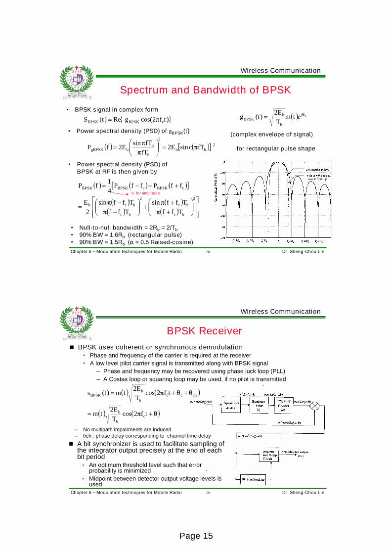
Spectrum and Bandwidth of BPSK
)2cos(Re)( tfgtS cBPSKBPSK cj
b
bBPSK etm
TE
tg 2)(
(complex envelope of signal)• Power spectral density (PSD) of gBPSK(t)
22
sin2sin
2 bbb
bbgBPSK fTcE
fTfT
EfP
• Power spectral density (PSD) ofBPSK at RF is then given by
22sinsin
2
41
bc
bc
bc
bcb
cBPSKcBPSKBPSK
TffTff
TffTffE
ffPffPfP
• BPSK signal in complex form
for rectangular pulse shape
• Null-to-null bandwidth = 2Rb = 2/Tb• 90% BW = 1.6Rb (rectangular pulse)• 90% BW = 1.5Rb (= 0.5 Raised-cosine)
½ for amplitude
Wireless Communication
Chapter 6 –Modulation techniques for Mobile Radio 29 Dr. Sheng-Chou Lin
BPSK Receiver BPSK uses coherent or synchronous demodulation
•Phase and frequency of the carrier is required at the receiver•A low level pilot carrier signal is transmitted along with BPSK signal
–Phase and frequency may be recovered using phase luck loop (PLL)–A Costas loop or squaring loop may be used, if no pilot is transmitted
A bit synchronizer is used to facilitate sampling ofthe integrator output precisely at the end of eachbit period• An optimum threshold level such that error
probability is minimized• Midpoint between detector output voltage levels is
used
tfTE
tm
tfTE
tmts
cb
b
chccb
bBPSK
2cos2
2cos2
)(
– No multipath impairments are induced– ch : phase delay corresponding to channel time delay

Page 16
Wireless Communication
Chapter 6 –Modulation techniques for Mobile Radio 30 Dr. Sheng-Chou Lin
Differential PSK
Differential PSK is a noncoherent form of PSK•Noncoherent receivers are cheap and easy to build, and hence are widely used in
wireless communications reduced receiver complexity•The input binary sequence is first differentially encoded and the modulated using a
BPSK modulator
DPSK transmitter
DPSK Receiver
•(Energy efficiency)DPSK is 3dBinferior to (Energy efficiency)cPSK
– Given the same error rate, requiredpower is 3dB higher for DPSK
1 kkk dmd
coherent
o
bDPSKe N
EP exp
21
,
Wireless Communication
Chapter 6 –Modulation techniques for Mobile Radio 31 Dr. Sheng-Chou Lin
Quadrature Phase-Shift Keying (QPSK)
QPSK has twice bandwidth efficiency of BPSK•Two bits are transmitted in a single modulation symbol•Four equally spaced-value phase: 0, /2, and 3/2
4,3,2,102
12cos2
)(
iTtitf
TE
tS scs
sQPSK
Ts: Symbol duration = 2Tb (Bit period)
)2(sin2
)1(sin2
)2(cos2
)1(cos2
)( tfiTE
tfiTE
tS cs
sc
s
sQPSK
)2cos(2
)(1 tfT
t cs
)2sin(2
)(2 tfT
t cs
• Two-dimensional constellation diagram
22
/powe.avgss ArSTE
Es/Ts=S avg. Power=A2/2
A= 2Es/ Ts
)(2
)1(sin)(2
)1(cos)( 21 tiEtiEtS ssQPSK
j = 1, 2

Page 17
Wireless Communication
Chapter 6 –Modulation techniques for Mobile Radio 32 Dr. Sheng-Chou Lin
Symbol Error Probability and Spectrum
•The distance between adjacent points = 2Es = 2 Eb, where Es = 2Eb
00
2
1,
22
22
22
)(NE
QNE
QN
dQPsymbolP bb
j o
ijsQPSKe
• Bit error rate of QPSK = BPSK• QPSK provides twice spectral efficiency with the same energy efficiency,
compared to BPSK• QPSK can also be differentially encoded
Spectrum and Bandwidth
22
22
22sin
22sin
sinsin2
bc
bc
bc
bcb
sc
sc
sc
scsQPSK
TffTff
TffTff
E
TffTff
TffTffE
fP
• Rs = Rb/2• Null-to-null bandwidth = 2Rs = 2/Ts= Rb
j = 1,2 for adjacentpoints
0,,
22/)()(
NE
QsymbolPbitP bQPSKeQPSKe 1 symbol = 2 bits
Wireless Communication
Chapter 6 –Modulation techniques for Mobile Radio 33 Dr. Sheng-Chou Lin
Transmission•Unipolar binary message stream bipolar
NRZ sequence•Bit stream m(t) mI(t) and m Q(t) (I
and Q streams), Rs = Rb/2
•The two binary sequences are modulated bytwo carriers 1(t) and 2(t)
•The two modulated signals are summed•RF filter confines the PSD within allocated
band: prevents signal adjacent channel,and remove out-of-band spurious duringmodulation
Detection•BPF removes out-of-band noise and ADJ
(adjacent channel interference)•Coherently demodulated using I,Q carriers•Decision circuit•The two components are multiplexed to
produce original sequence
BPSK Transmission and Detection

Page 18
Wireless Communication
Chapter 6 –Modulation techniques for Mobile Radio 34 Dr. Sheng-Chou Lin
Offset QPSK The occasional phase shift of radians can cause signal envelope to pass
through zero for just an instant•Any kind of hardlimiting or nonlinear amplification of zero-crossings brings back filtered
sidelobes– QPSK signals use pulse shaping use pulse shaping be amplified only using linear amplifiers
which are less efficient– OQPSK ensures power baseband signal transitions applied to RF amplifier, which helps
eliminate spectrum regrowth after amplification (more efficient amplification)
OQPSK is similar to QPSK, except for time alignment of even and odd bit streams
• Even abd odd bit streams, mI(t) andmQ(t), are offset bye one bit period(alf-symbol period)
• Maximum phase shift is limited to 90o (180o for QPSK) envelopevariations are considerably less
• OPSK perform better than QPSK inthe presence of phase jitter due tonoisy reference signals
Wireless Communication
Chapter 6 –Modulation techniques for Mobile Radio 35 Dr. Sheng-Chou Lin
/4 QPSK Transmission
•mk mI,k, mQ,k I,k, Q,k
•I,k, Q,k are determined by their previous values
•k: a function of the current symbols mI,k, mQ,k
kkk
kkkkkk
kkkkkk
QIQ
QII
1
11
11
sincossin
sincoscos
ttQtcontIts ccQPSK sin)(4/
2/cos2/)(1
0
1
0ss
N
kkss
N
kk TkTtpTkTtpItI
2/sin2/)(1
0
1
0ss
N
kkss
N
kk TkTtpTkTtpQtQ
All possible states
k-1=n/4 k-1=n/2
P(t): Pulse shape
• Ik, Qk are usually passed through raised cosine rolloff pulseshaping filters
• I(t) and Q(t) can take one of five possible values, 0,+1,-1,+1/2, -1/ 2
•The information is completely contained in the phasedifference, it is possible to use noncoherent differentialdetection even in the absence of differential encoding

Page 19
Wireless Communication
Chapter 6 –Modulation techniques for Mobile Radio 36 Dr. Sheng-Chou Lin
/4 DQPSK Transmission
Example: Bit stream 0 0 1 0 1 1 is to be sent using /4 DQPSK, o=0o. Determine k, and Ik, Qk
•First two bits: 0 0 1 = -3 /4 1= o + 1 = -3 /4 I1, Q1= (-0.707, -0.707)
•Second two bits: 1 0 2 = -/4 2= 1 + 2 = -I2, Q2 = (-1,0)
•Third two bits: 1 1 3 = /4 2=1 + 2 = -3 /4 I3, Q3 = (-0.707, -0.707)
•BER of /4 DQPSK is 3dB inferior toQPSK, while
– BER/4 CQPSK = BERCQPSK
– In low bit rate, fast Rayleigh fadingchannels, differential detection offersa lower error rate
/4 DQPSK Transmitter
Wireless Communication
Chapter 6 –Modulation techniques for Mobile Radio 37 Dr. Sheng-Chou Lin
/4 DQPSK Detection
• Baseband differential detection
• IF differential detection
• FM discriminator detection
Baseband differential detection
IF differential detection
FM discriminator detection

Page 20
Wireless Communication
Chapter 6 –Modulation techniques for Mobile Radio 38 Dr. Sheng-Chou Lin
Constant Envelope Modulation
Nonlinear modulation methods•Amplitude of carrier is constant, regardless of variation in modulating signal,•Used in many practical mobile radio communication•Advantage
–Power efficient Class C amplifier can be used without introducing degradation–Low out-of-band radiation of the order –60dB to –70dB–Limiter-discriminator detection can be used high immunity against random FM
noise fluctuation due to Rayleigh fading
•Occupy a larger bandwidth than linear modulation schemes– Is not well-suited in situations where bandwidth efficiency is more important than power
efficiency
Nonlinear modulation schemes•Frequency Shift Keying (FSK)•Minimum Shift Keying (MSK)
–Gaussian Minimum Shift Keying (GMSK)
Wireless Communication
Chapter 6 –Modulation techniques for Mobile Radio 39 Dr. Sheng-Chou Lin
FSK and MSK
Signal space diagram forCPFSK (continuous phaseFSK)
MSK transmitter
MSK phasor diagram
FSK transmitter

Page 21
Wireless Communication
Chapter 6 –Modulation techniques for Mobile Radio 40 Dr. Sheng-Chou Lin
Binary Frequency Shift Keying (BFSK)•Carrier signal is switched between two values according to the two possible
message states (high and low tones)
)1(0,22cos2
binaryTttffTE
tts bcb
bHFSK
)0(0,22cos2
binaryTttffTE
tts bcb
bLFSK
2f : a constant offset
•FSK signals is switched between two independent oscillators–Waveform is discontinuous at switching time discontinuous FSK
)binary(Tt,tfcosTE
tts bHb
bHFSK 102
21
)binary(Tt,tfcosTE
tts bLb
bHFSK 002
22
– Phase discontinuous pose spectral spreading and spurious transmissions– Is generally not used in highly regulated wireless systems
t
fcb
bc
b
bFSK dmktf
TE
ttfTE
ts 22cos2
)(2cos2
• More common method for generating FSK signal ( similar to analog FM)
Wireless Communication
Chapter 6 –Modulation techniques for Mobile Radio 41 Dr. Sheng-Chou Lin
Spectrum and detection of BFSK
Spectrum and Bandwidth•Power spectral density consists of
discrete frequency components atfc, fc+nf, fc-nf, where n is aninteger–Continuous phase FSK falls off
inverse fourth power–Discontinuous phase FSK falls off
inverse square power•Transmission bandwidth BT is given by
Carson’s rule as
BT = 2 f + 2B; B is bandwidth ofdigital baseband signal–B = R for rectangular pulse
assuming first null bandwidth isused
–B = (1+)R/2 for raised cosinepulse-shaping
Detection• Coherent Detection (optimum detector)
Correlator # 1
Correlator # 2
0, N
EQP b
FSKe
• Noncoherent Detection: matched filters
t = kTb
Matched filter
o
bDPSKe N
EP
2exp
21
,

Page 22
Wireless Communication
Chapter 6 –Modulation techniques for Mobile Radio 42 Dr. Sheng-Chou Lin
Minimum Shift Keying (MSK) MSK is a special type of CPFSK
•CPFSK with peak frequency deviation = ¼ Rb(bit rate); modulation index of 0.5; kFSK=(2F) / RbF= peak RF
•The minimum frequency spacing allows two FSK signals to be coherently orthogonaland orthogonal detection.
Representation of an MSK signal as a form of two staggered binary PSKsignals, each with a sinusoidal envelope
MSK
Offset QOSK(rectangular)
Conventional QPSK(rectangular)
Odd bit
Even bit
Wireless Communication
Chapter 6 –Modulation techniques for Mobile Radio 43 Dr. Sheng-Chou Lin
Minimum Shift Keying (MSK) Advantages and properties
•Spectrally efficient modulation and is particular attractive for use in mobileradio communication systems
•Constant envelope, spectral efficiency, good BER performance, self-synchronizing capability
•Can be seen as a special form of 0QPSK; baseband rectangular pulses half-sinusoidal pulses of a period of 2Ts
1
0
1
02sin22cos2
N
i
N
icbbQcbIMSK tfTiTtptmtfiTtptmts
ii
elsewhere
TtTt
tp bb
0
202
cos mIi(t): odd bits; in-phase
mQi(t): Even bits; quadratureFor bipolar series dataFeed at a rate of Rb/2
k
bQIc
b
bMSK T
ttmtmtf
TE
tsii
2
2cos2k: 0 or depending on
mI (t) is 1 or -1
• MSK is an FSK signal with binary signaling frequencies fc +1/4T and fc-1/4T• With constant amplitude, MSK can be amplified using efficient nonlinear amplifier• Continuous phase makes it highly desirable for highly reactive loads
Page 23
Wireless Communication
Chapter 6 –Modulation techniques for Mobile Radio 44 Dr. Sheng-Chou Lin
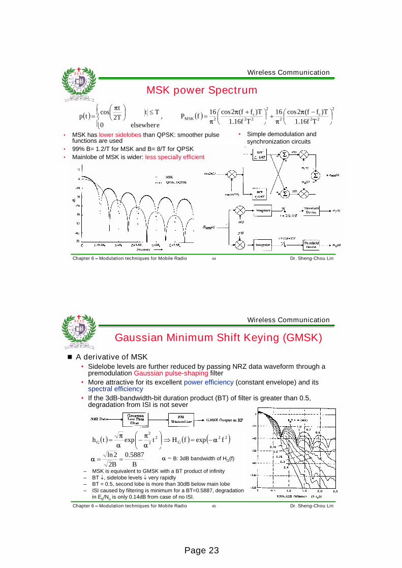
MSK power Spectrum
• MSK has lower sidelobes than QPSK: smoother pulsefunctions are used
• 99% B= 1.2/T for MSK and B= 8/T for QPSK• Mainlobe of MSK is wider: less specially efficient
,0
2cos
elsewhere
TtTt
tp
2
222
2
222 16.1)(2cos16
16.1)(2cos16
Tf
TffTf
TfffP cc
MSK
• Simple demodulation andsynchronization circuits
Wireless Communication
Chapter 6 –Modulation techniques for Mobile Radio 45 Dr. Sheng-Chou Lin
Gaussian Minimum Shift Keying (GMSK)
A derivative of MSK•Sidelobe levels are further reduced by passing NRZ data waveform through a
premodulation Gaussian pulse-shaping filter•More attractive for its excellent power efficiency (constant envelope) and its
spectral efficiency•If the 3dB-bandwidth-bit duration product (BT) of filter is greater than 0.5,
degradation from ISI is not sever
2222
2
expexp ffHtth GG
~ B: 3dB bandwidth of HG(f)BB
5887.02
2ln
– MSK is equivalent to GMSK with a BT product of infinity– BT , sidelobe levels very rapidly– BT = 0.5, second lobe is more than 30dB below main lobe– ISI caused by filtering is minimum for a BT=0.5887, degradation
in Eb/No is only 0.14dB from case of no ISI.

Page 24
Wireless Communication
Chapter 6 –Modulation techniques for Mobile Radio 46 Dr. Sheng-Chou Lin
GMSK Bit Error Rate
Occupied RF bandwidth•Example: 0.25GMSK, channel data rate Rb=270 kbps
– T = 1/Rb = 1/(270103) = 3.7 s, BT =0.25 B= 0.25/T= 0.25/ (27010-6) =67.567 kHz
– For 90%, power bandwidth = 0.57Rb 90% RFBW= 0.57Rb =0.57270103 =153.9 kHz
Bit Error Rate:•A function of BT, since pulse shaping impact ISI•Offer performance within 1dB of optimum MSK as BT = 0.25
0,
2N
EQP b
GMSKe Is a constant related to BT
)(85.0
25.068.0BTMSKsimplefor
BTwithGMSKfor
Wireless Communication
Chapter 6 –Modulation techniques for Mobile Radio 47 Dr. Sheng-Chou Lin
GMSK Transmitter and Receiver
Transmitter•NRZ Gaussian baseband filter
FM modulatorUS cellular•Used in Digital Packet Data (CDPD)
and Global System for Mobile (GSM)system
GMSK receiver
Logic logic circuit for GMSK demodulation
GMSK transmitter
Detection•Orthogonal coherent detectors
–Carrier recovery is similar toCoseas loop
–A PLL with a frequency doubler:can be easily implemented usingdigital logic
•Noncoherent detectors: standard FMdiscriminators

Page 25
Wireless Communication
Chapter 6 –Modulation techniques for Mobile Radio 48 Dr. Sheng-Chou Lin
M- ary Modulation
Combined linear and constant Envelop Modulation•Digital baseband data may be sent by varying both envelope and phase (or
frequency) of an RF carrier•M possible signals, s1(t), s2(t), …, sM(t) is transmitted during each symbol
period of duration Ts, M = 2n, one symbol = log2M bits•M-ary ASK (amplitude), M-ary PSK (frequency), M-ary FSK(frequency), M-ary
QAM (amplitude and phase)
•Particularly attractive for use in bandlimited channels– M-ary modulation schemes can achieve better bandwidth efficiency at expense of
power efficiency– Example: BW(8-PSK)= 1/3 BW(BPSK), Log28 = 3; BER is significantly worse than
BPSK
•Limited in applications due tosensitivity to time jitter– Smaller distance between signals
timing errors error performance
QPSK8-PSK
Wireless Communication
Chapter 6 –Modulation techniques for Mobile Radio 49 Dr. Sheng-Chou Lin
M-ary Phase Shift (MPSK)
The carrier phase takes on one of M possible values
MiTtM
itfTE
tS scs
si ,,3,2,10
212cos
2)(
Es/Ts= S avg. Power= A2/2 A = 2Es/ Ts
Es = (log2M) Eb: symbol Energy; Ts = (log2M) Tb: Symbol period
)2(sin2
)1(sin2
)2(cos2
)1(cos2
)( tfM
iTE
tfM
iTE
tS cs
sc
s
si
)2cos(2
)(1 tfT
t cs
)2sin(2
)(2 tfT
t cs
• Two-dimensional constellation diagram
)(2
)1(sin)(2
)1(cos)( 21 tM
iEtM
iEtS ssMPSK
j = 1, 2sE
– M-ary message points are equally spaced on a circle of radius 2Escentered at the origin
– MPSK is a constant envelope signal when no pulse shaping is used
MEs
sin2

Page 26
Wireless Communication
Chapter 6 –Modulation techniques for Mobile Radio 50 Dr. Sheng-Chou Lin
Error Probability and Power Spectra
• Distance between adjacent symbols = 2 Es sin(/ M); Average symbol error probability
MNME
QN
MEQ
Nd
QsymbolP bs
j o
ijMPSKe
sin
log22
2)/sin(2
22
)(0
2
0
2
1,
Es = (log2M) Eb
MNE
QsymbolP sMPSKe
sin
42)(
0,
For a differential M-ary PSK system
Power Spectra of M-ary PSK
2
2
2
2
2
22
22
log2log2sin
log2logsin
2log
sinsin2
MTffMTff
MTffMTffME
TffTff
TffTffE
fP
bc
bc
bc
bcb
sc
sc
sc
scsQPSK
• These values assume no timing jittering orfading; a large negative effect on bit error rateas M increases.
• Simulation must be used to determine bit errorin wireless channels (interference andmultipath)
Ts = (log2M) Tb: Symbol period
Wireless Communication
Chapter 6 –Modulation techniques for Mobile Radio 51 Dr. Sheng-Chou Lin
Bandwidth and Power Efficiency
As M , first null bandwidth of M-ary PSK while Rb is heldconstant•Bandwidth efficiency B = Rb/B
As M , constellation is more densely packed•Error probability , Eb/No is held constant•Power efficiency (noise tolerance)
– Ideal Nyquist Pulse Shaping– First null bandwidth
• Pilot symbols or equalization must beused; This has not been a popularcommercial practice

Page 27
Wireless Communication
Chapter 6 –Modulation techniques for Mobile Radio 52 Dr. Sheng-Chou Lin
M-ary Quadrature Amplitude Modulation (QAM)QAM: allow amplitude to also vary with phase
)2(sin2
)1(sin2
)2(cos2
)1(cos2
)( minmin tfM
ibTE
tfM
iaTE
tS cis
cis
i
Emin energy of signal with lowest amplitude
)2cos(2
)(1 tfT
t cs
)2sin(2
)(2 tfT
t cs
ai, bi: independent integers = - (L-1), -(L-3), …, 0, ...(L-1), (L-3)MiTt s ,,3,2,10
• energy per symbol is not constant• Distance between states is also not constant
ML
-3 3-1
1
1-1
3
-3
0
0
min,
131
14
2114)(
NME
QM
NE
QM
symbolP
av
MQAMe
min132
EMEav
– Power spectrum, bandwidth efficiency: QAM = M-ary PSK
– Power efficiency: QAM is superior to M-ary PSK
– Pilot symbols or equalization must be used
Wireless Communication
Chapter 6 –Modulation techniques for Mobile Radio 53 Dr. Sheng-Chou Lin
M-ary Frequency-Shift Keying (MFSK)
)1(0,cos2
binaryTttinTT
Etts bc
ss
sHFSK
• fc = nc / 2Ts for some fixed integers nc• M transmitted signals are of equal energy and equal duration• Signal frequencies are separated by 1/2Ts Hz, making signals orthogonal to one another
Coherent M-ary FSK: optimum receiver consists of a bank of M correlators, or matchedfilters
o
be N
MEQMP 2log
1
Coherent M-ary FSK: matched filters followed by envelope detectors
o
s
o
sM
k
k
e NEM
NkkE
kM
kP
2exp
21
1exp
11
11
1
1 Binomial expansion
M
MRB b
2log23
MMR
B b
2log2
• M- FSK are bandwidth inefficient: As M , bandwidth efficiency of M-ary FSK • M- FSK are power efficient: As M , power efficiency of M-ary FSK • Can be amplified using nonlinear amplifiers with no performance degradation

Page 28
Wireless Communication
Chapter 6 –Modulation techniques for Mobile Radio 54 Dr. Sheng-Chou Lin
DCPSK on nonfading channel
Differently coherent phase shift keying (DCPSK)•If we define then the average error rate isSNR
ePr 21
powerNoisepowerSignal
(DCPSK)
erfcPr 21
(BPSK)
The received signal is given by kctfiAeRe 2 Signal power = A2 / 2
The received signal under cellular propagation is given by
kctfiAreRe 2 Signal power = A2 r2 / 2 = 2 / 2
N22
othewrise
eP0
022 2
2
(Rayleigh Distribution)
Wireless Communication
Chapter 6 –Modulation techniques for Mobile Radio 55 Dr. Sheng-Chou Lin
Modulation Performance in fadingand multipath channels
Radio channel impairments: Fading; Multipath; Doppler spread•A transmitted signal will suffer deep fades Outage, loss of sign
–Bit error rate gives a good indication, it does not provide incidents ofbursty errors
–Probability of Outage: Another means to judge effectiveness of signaling
BER and Outage evaluation methods under varioustypes of channel impairments
–Analytical techniques Slow flat-fading channel–Computer Simulation Frequency-selective channel
–Input bit stream channel counting at theoutput of receiver decision circuit
Outage
1010010 1010110
ErrorCounting
TX Channel RX
Decision
Page 29
Wireless Communication
Chapter 6 –Modulation techniques for Mobile Radio 56 Dr. Sheng-Chou Lin
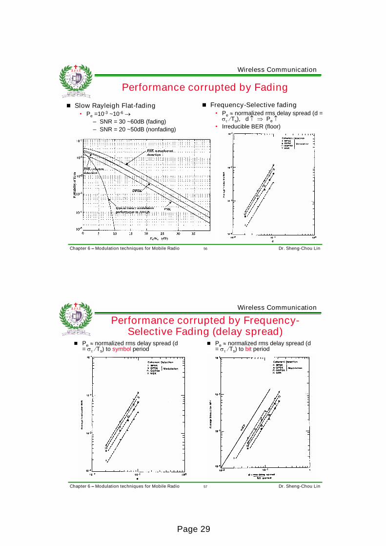
Performance corrupted by Fading
Slow Rayleigh Flat-fading•Pe =10-3 ~10-6
–SNR = 30 ~60dB (fading)–SNR = 20 ~50dB (nonfading)
Frequency-Selective fading•Pe normalized rms delay spread (d =
Ts), d Pe • Irreducible BER (floor)
Wireless Communication
Chapter 6 –Modulation techniques for Mobile Radio 57 Dr. Sheng-Chou Lin
Performance corrupted by Frequency-Selective Fading (delay spread)
Pe normalized rms delay spread (d= Ts) to symbol period
Pe normalized rms delay spread (d= Ts) to bit period

Page 30
Wireless Communication
Chapter 6 –Modulation techniques for Mobile Radio 58 Dr. Sheng-Chou Lin
Computer Simulation BER evaluation normalized parameters
•Doppler Spread (vehicle speed): BDTs, BD/RS
•Muttipath Delay (delay of the second multipath ): /T•Ratio of average energy to noise power spectral density: Eb/No dB•Average carrier to interference power ratio : C/I dB•Average main-path to delayed-path power ratio: C/D dB
BERSIM Concept• Actual digital
communication• Baseband digital
hardware simulatorwith softwaresimulation as a driverfor real-time BERcontrol
CD
C/D
Wireless Communication
Chapter 6 –Modulation techniques for Mobile Radio 59 Dr. Sheng-Chou Lin
Performance corrupted by CCI
/4 DQPSK system•C/N for different CCI•Slow Rayleigh flat-fading•Multipath time dispersion and
Doppler spread are negligible•Errors are caused mainly by
fades and CCI•For C/I > 20dB, errors are
primarily due to fading,interference has little effect
•C/I < 20dB, interferencedominates the linkperformance
•High-capacity mobile systemsare interference limited, notnoise limited.
C/I = 20dB
C/I = 30dB
C/I = 40dB
C/I = 50dBC/I = dB
fc = 850 MHzfs = 24kspsRoll-off = 0.2

Page 31
Wireless Communication
Chapter 6 –Modulation techniques for Mobile Radio 60 Dr. Sheng-Chou Lin
Performance corrupted by Speed IF no time dispersion and C/N , BER does not decrease below a
certain irreducible floor•Irreducible is caused is due to random FM (caused by Doppler spread)•Doppler-induced fading (Ex: /4 DQPSK fc = 850 MHz, fs = 24ksps, Roll-off = 0.2)
•Velocity error floor , C/D error floor
Eb/No= 100dBC/I= 100dB
BER in Raleigh flat-fading channelfor various mobile speed
BER in two-ray Raleigh flat-fading channelfor various time delay
C/D = 0dB
C/D = 10dB
Wireless Communication
Chapter 6 –Modulation techniques for Mobile Radio 61 Dr. Sheng-Chou Lin
DCPSK on Fading Channel Average SNR and average error probability on fading Channel
2222 2 yxE 0
222
212
NNN
(average signal) (average SNR)
0
2
222
0
2
2
22 11
ee
NNe
ddP
P NN
ePr 21
Average probability of error due to Rayleigh fading is
000
11
00
121
111
21
211
21 00
dedeedPPP rb
N
2
0
where
(SNR distribution)
Given
• To average the error probability in AWGN over the possible ranges of signalstrength due to fading

Page 32
Wireless Communication
Chapter 6 –Modulation techniques for Mobile Radio 62 Dr. Sheng-Chou Lin
Performance on Fading Channel
If Error performance criteria us such that the error rate does notexceed 10-3(Typically the criteria hosen for conventionaltransmission)
Without Rayleigh fading
dB..ePr 97214661021 3
o
b
o
b
o
b
NE
)T/(NT/E
BNT/E
NS
1
1
With Rayleigh fading
dB.Pb 98264991012
10
3
0
(DCPSK)
Require SNR is much higherover a fading channel
Wireless Communication
Chapter 6 –Modulation techniques for Mobile Radio 63 Dr. Sheng-Chou Lin
BPSK Performance under fading (1) BPSK under coherent detection scheme (cophasing is assumed)
erfcPr 21 0
0
1
eP
00
21
0
00
21
0
11
0
00
111
1211
111
121
111
121
211
121
22
0121
121
0
0
0
0
de
de
de
de
eerfce
deerfcdPPP rb
(BPSK) < ePr 21
(DCPSK)
dtexerfc
xerfcxQ
xx
2222
1
21
110
1
nn
dxexx xn
Average error rate
Gamma Function
Gamma Function
Q=function
011

Page 33
Wireless Communication
Chapter 6 –Modulation techniques for Mobile Radio 64 Dr. Sheng-Chou Lin
BPSK Performance under fading (2)
0
0
210
0
00
41
211121
11121
111
121
121
0
deerfcdPPP rb
111 x,nxx n
Gamma Function
111
00
1
n,nn
n,dxexx xn
n Can be evaluated from the recursive relation
11 nnxProvided one knows the value of 10 nforn
!nx 1 In n is an integer
Without Rayleigh fading
dB..
erfcPr
856844
1021 3
With Rayleigh fading
dB.
Pb
9823250
1041
0
3
0
As
Wireless Communication
Chapter 6 –Modulation techniques for Mobile Radio 65 Dr. Sheng-Chou Lin
Digital Modulation under fading (1)
Performance in slow, flat fading channels in AWGN
•= [ Eb/ No] 2 is the averagevalue of signal-to-noise ratio, has a Rayleigh distribution
•Mean SNR is significantly largerthan that required when operatingover a nonfading channel (~20-50dB)
Fading v.s. nonfading
Page 34
Wireless Communication
Chapter 6 –Modulation techniques for Mobile Radio 66 Dr. Sheng-Chou Lin
Digital Modulation under fading (2)Rayleigh fadingAWGN
Wireless Communication
Chapter 6 –Modulation techniques for Mobile Radio 67 Dr. Sheng-Chou Lin
Digital Modulation under fading (3)Rayleigh fadingNakagami fading BPSK

Page 35
Wireless Communication
Chapter 6 –Modulation techniques for Mobile Radio 68 Dr. Sheng-Chou Lin
Diversity techniques for fading channels Diversity Reception: Different methods of receiving “independent”fading
signals
•Space Diversity•Frequency Diversity•Polarization Diversity•Angular Diversity•Time Diversity
Different was of combining thesignals (space diversity)•Pure Selection•Equal Gain Combining•Maximal-Ratio Combining
Independent of what type of Diversity isused, it has
•M branch diversity, m different signals•Those signals are statistically independent•The same signal power and noise power
Model of digital comm. With diversity
Space diversity
Wireless Communication
Chapter 6 –Modulation techniques for Mobile Radio 69 Dr. Sheng-Chou Lin
Diversity techniques
Rake receiver time diversity
Polarization diversity
OFDM Frequency diversity
Diversity implementation
• Antenna polarization diversity• OFDM (Frequency diversity)• Rake receiver (time diversity)

Page 36
Wireless Communication
Chapter 6 –Modulation techniques for Mobile Radio 70 Dr. Sheng-Chou Lin
Pure Selection Diversity (SL)
Pure selection techniques chose the signal with the largestinstantaneous power•The selected signal•The signal-to-noise ratio of the selected signal•Find pdf of
mr,.....,r,rmaxz 21 m,.....,,max 21
32121 ,...,,FF
m...,
im
i,r im...F,...,,FP 132121
If they are independent
ji jiFF For all i
x
y
011
00
0
iii ,eFeP i
i
i
i
ofpdfeem
P
ddF
PeF
m
m
,1
1
00
0
1
0
zY,zXP
zy,xmaxPzZP
z
Wireless Communication
Chapter 6 –Modulation techniques for Mobile Radio 71 Dr. Sheng-Chou Lin
PDF& CDF with SL Diversity
A
t
............................
.. .... ...
path 1
path 2
.maximum amplitude
rP
Page 37
Wireless Communication
Chapter 6 –Modulation techniques for Mobile Radio 72 Dr. Sheng-Chou Lin
DCPSK Error rate with SL Diversity
Consider Binary DCPSK ePr 21
Average probability of error due to Rayleigh fading
0100000
212
0000
2
000
11
0
1
0
11
0
1
00
11
1
00
!211
43
32
21
121
11
21
111
11
1121
01
1121
121
121
00
000
00
00
00
i
mm
mmmm
deemm
deemem
eem
dem
e
deem
edPPP
m
i
m
mm
m
m
rb
dxvuuvdxvu 0
Wireless Communication
Chapter 6 –Modulation techniques for Mobile Radio 73 Dr. Sheng-Chou Lin
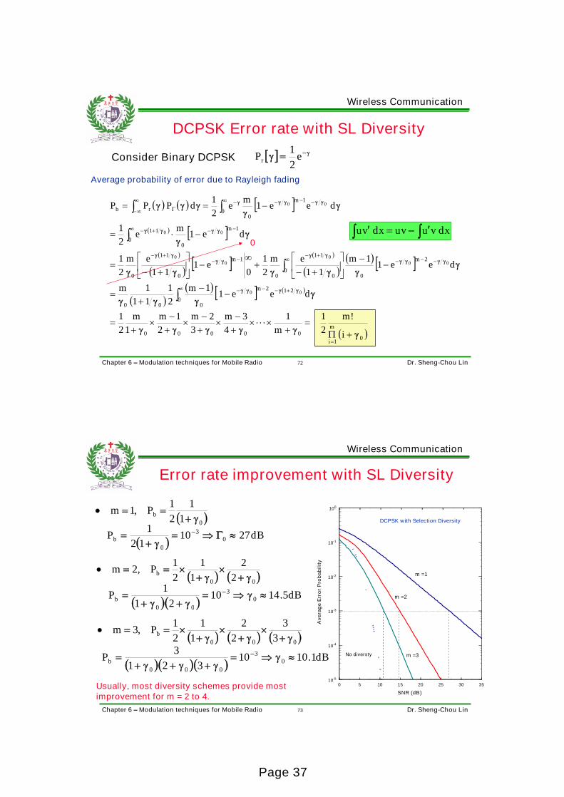
Error rate improvement with SL Diversity
011
21
1
bP,m
00 22
11
21
2
bP,m
dBPb 271012
10
3
0
dB.Pb 5141021
10
3
00
000 33
22
11
21
3
bP,m
dB.Pb 11010321
30
3
000
0 5 10 15 20 25 30 35
SNR (dB)
10-5
10-4
10-3
10-2
10-1
100
Ave
rag
eE
rro
rP
rob
abili
ty
m =1
m =2
m =3No diversty
DCPSK with Selection Diversity
Usually, most diversity schemes provide mostimprovement for m = 2 to 4.

Page 38
Wireless Communication
Chapter 6 –Modulation techniques for Mobile Radio 74 Dr. Sheng-Chou Lin
Maximal-Ratio Diversity
The signals from all of the M branches are weighted according to theirindividual signal voltage to noise power ratios and then summed.•Output SNR is equal to the sum of the individual SNR•The advantage of generating an output with an acceptable SNR even when none of the
individual signals are acceptable•The best statistical reduction of fading of any know linear diversity•DSP and digital receivers are now making this optimal form of diversity practical
The combined signal
•The signal-to-noise ratio
m
iiirar
1
m
iii
m
iii
m
iii Na
ra
Na
r
1
2
2
1
1
2
2 22
Wireless Communication
Chapter 6 –Modulation techniques for Mobile Radio 75 Dr. Sheng-Chou Lin
PDF with Maximal-Ratio Combining (1)• We set iii Nsa
m
ii
m
i i
im
i i
im
iii
m
iii
m
iiii
m
iiii
Nr
Nr
Nr
Nr
NrN
Nrr
11
2
1
2
1
2
2
1
2
1
22
2
1 2212
12
• Find pdf of
21
02
0
01
PPPeP iii
i
If n = 2 21 And 21 and Are I.I.d.
01
011
00
00
00
20
020
000
2
,ede
deeP
1P
2P
Page 39
Wireless Communication
Chapter 6 –Modulation techniques for Mobile Radio 76 Dr. Sheng-Chou Lin
PDF of Maximal-Ratio Combining (2)
01
011
00
00
00
20
020
000
2
,ede
deeP
otherwise,
,!m
eP m
m
m
0
01
0
0
1
otherwise,
,ede
deePPP
0
02
1
1
00
00
3
30
2
030
00
20
23
rP
Wireless Communication
Chapter 6 –Modulation techniques for Mobile Radio 77 Dr. Sheng-Chou Lin
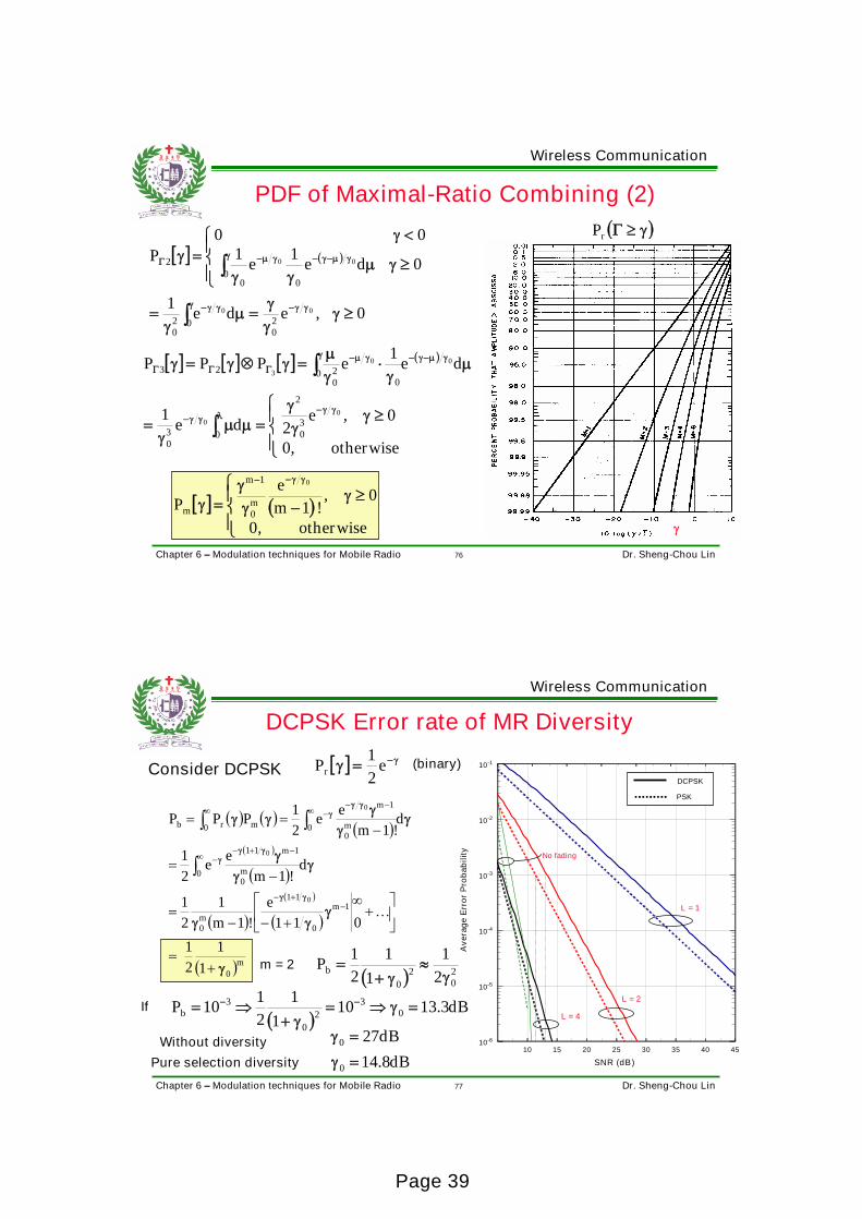
DCPSK Error rate of MR Diversity
Consider DCPSK ePr 21 (binary)
m
mm
m
m
m
m
mrb
em
dm
ee
dm
eePPP
0
1
0
11
0
00
111
00
1
0
11
21
011!11
21
!121
!121
0
0
0
dB.Pb 31310
11
21
10 03
20
3
Without diversity
Pure selection diversity
m = 2
dB270
dB.8140
If
20
20 2
11
121
bP
10 15 20 25 30 35 40 45
SNR (dB)
10-6
10-5
10-4
10-3
10-2
10-1
Ave
rag
eE
rro
rP
rob
abili
ty
L = 1
L = 2
L = 4
No fading
DCPSK
PSK

Page 40
Wireless Communication
Chapter 6 –Modulation techniques for Mobile Radio 78 Dr. Sheng-Chou Lin
BPSK Error rate with MR Diversity (1)
erfcPr 21
(BPSK)
otherwise,
,!m
eP m
m
m
0
012
0
0
1
21
!21
!21
!21
22
!21
22
!121
0!121
01sin,!12
1
!121
00
121
00
21
0
00
000
0
1
0
00
1
0
0
0
mm
dem
dem
de
md
emm
erfcmm
forecedm
erfc
dm
eerfcPPP
mm
mm
m
m
m
m
m
m
m
m
m
m
m
mrb
m
xn
mm///m/m/n
/,nnndxexn
213212
2121232121
21110
1
0
Wireless Communication
Chapter 6 –Modulation techniques for Mobile Radio 79 Dr. Sheng-Chou Lin
BPSK Error rate with MR Diversity (2)
mmmmmmb m
mmmmmm
mP
01
01
0 !2!!12
!213212
213212
!21
Two-branch diversity dB.!!
Pb 36111016
3223
03
20
20
3
No diversity dB.Pb 97231041
21
03
20
20
2
dB.P mb 31310
11
21
03
0
dB.Pb 98264991012
10
3
0
Two-branch diversity
No diversity
• BPSK
• DCPSK
CPSKPDCPSKP bb
1355133
!!!!

Page 41
Wireless Communication
Chapter 6 –Modulation techniques for Mobile Radio 80 Dr. Sheng-Chou Lin
Comparison between Precise andapproximate error rate with ML
10 15 20 25 30 35 40 45
SNR (dB)
10-6
10-5
10-4
10-3
10-2
10-1
Ave
rag
eE
rro
rP
rob
abili
ty
L = 1
L = 2
L = 4
No fading
DCPSK
PSK
Wireless Communication
Chapter 6 –Modulation techniques for Mobile Radio 81 Dr. Sheng-Chou Lin
Comparison between SL and ML
0 5 10 15 20 25 30 35 40 45
SNR (dB)
10-6
10-5
10-4
10-3
10-2
10-1
Ave
rag
eE
rro
rP
rob
abili
ty
0 5 10 15 20 25 30 35 40 45
SNR (dB)
10-6
10-5
10-4
10-3
10-2
10-1
Ave
rag
eE
rro
rP
rob
abili
ty
Selection diversity Maximal-Ration diversity
DCPSK
PSK
DCPSK
No fading
L = 1
L = 2L = 4
L = 1
L = 2
L = 4
Nofading

Page 42
Wireless Communication
Chapter 6 –Modulation techniques for Mobile Radio 82 Dr. Sheng-Chou Lin
Equal-Gain Diversity It may not always be convenient or desirable to provide the variable
weighting capacity required for true maximal-ratio combining.•The gains may be set to a constant value of unity equal-gain combining
Cophase &Summing
• The combined signal
m
iirr
1 mNr
N
rm
ii
22 2
1
2
• The signal-to-noise ratio
othewrise
er
rPiri
i
0
022 2
2
242
00
22
22
22
20 2
21
2
2
2
2
2
2
21
rerfc
re
rde
re
rforrPrPrPrPrrr
rr
rrrr
rPrPrPrPrrrr rrrr 321321 No closed form
Wireless Communication
Chapter 6 –Modulation techniques for Mobile Radio 83 Dr. Sheng-Chou Lin
No closed form or other techniques exist to evaluateexplicitly Pr(r) for m > 2. Numerical techniques can beused to evaluate Pr(r) for any value of m.
PDF with Equal-Gain Diversity
m
m
m
m
mP
me
P
0
1
0
1
!11
0,!1
0
(maximal-ratio)
012
2
0
11
,!m
mP m
mmm
• Same Type of approx. for equal-gain combining
!m
!mm
ratioimalmaxPgainequalP mm
b
b 112
2 1
For m = 2 3311
3222
.!!ratioimalmaxP
gainequalP
b
b

Page 43
Wireless Communication
Chapter 6 –Modulation techniques for Mobile Radio 84 Dr. Sheng-Chou Lin
Lesson 6 Complete