Ch6 Buildings
49
Chapter 6 Building Response In this chapter we will explore the nature of deformations and forces in buildings during earthquake shaking. Of course, buildings are complex connections of columns, beams, and walls, the study of which deserves and entire course in structural engineering. However, for our purposes, it is instructive to investigate the nature of forces and deformations that would occur in a solid body whose properties are similar to the average properties of a building. We begin with a simple description of different types of buildings and their characteristics. In general we will characterize buildings with the following parameters (refer to Figure 6.1). • Density is important because it is used to calculate inertial m omentum. The density of buildings ranges about 100 kg/m 3 (tall flexible frame buildings) to 200 kg/m 3 (stiff heavy shear wall buildings). Earthquake loads in buildings generally increase with the density of the building. • Yield strength is maximum horizontal load that can be applied to a building. It is expressed in units of acceleration if the yield force is normalized by the weight of the building. While increasing yield strength is generally desirable, it usually comes with the penalty of increasing stiffness. • Stiffness is the horizontal force distributed throughout a building divided by resulting lateral shear strain in the building (usually called drift). Maximum stresses in a building generally increases with stiffness, so making a building stiff can lead to high stresses. While low stiffness has advantages, decreasing stiffness usually comes with the penalties of increasing shear strains and decreasing yield strength. • Ductility refers to the ratio of the horizontal shear strain at which a building collapses divided by the strain at which a building begins to strain inelastically. Increasing ductility is always desirable, but it usually comes with the penalty of increasing cost. Figure 6.1 Idealized building response. 6-1
Transcript of Ch6 Buildings
8/6/2019 Ch6 Buildings
http://slidepdf.com/reader/full/ch6-buildings 1/49
Chapter 6 Building Response
In this chapter we will explore the nature of deformations and forces in buildings duringearthquake shaking. Of course, buildings are complex connections of columns, beams,
and walls, the study of which deserves and entire course in structural engineering.
However, for our purposes, it is instructive to investigate the nature of forces anddeformations that would occur in a solid body whose properties are similar to the average
properties of a building. We begin with a simple description of different types of
buildings and their characteristics. In general we will characterize buildings with the
following parameters (refer to Figure 6.1).
• Density is important because it is used to calculate inertial momentum. Thedensity of buildings ranges about 100 kg/m3 (tall flexible frame buildings) to 200kg/m3 (stiff heavy shear wall buildings). Earthquake loads in buildings generally
increase with the density of the building.
• Yield strength is maximum horizontal load that can be applied to a building. It isexpressed in units of acceleration if the yield force is normalized by the weight of
the building. While increasing yield strength is generally desirable, it usually
comes with the penalty of increasing stiffness.
• Stiffness is the horizontal force distributed throughout a building divided byresulting lateral shear strain in the building (usually called drift). Maximum
stresses in a building generally increases with stiffness, so making a building stiff
can lead to high stresses. While low stiffness has advantages, decreasing stiffnessusually comes with the penalties of increasing shear strains and decreasing yield
strength.
• Ductility refers to the ratio of the horizontal shear strain at which a building
collapses divided by the strain at which a building begins to strain inelastically.Increasing ductility is always desirable, but it usually comes with the penalty of
increasing cost.
Figure 6.1 Idealized building response.
6-1

8/6/2019 Ch6 Buildings
http://slidepdf.com/reader/full/ch6-buildings 2/49
The following examples give some idea of different classes of buildings.
Concrete Shear-Wall Buildings
This is a common class of buildings that generally have at least some walls that consist of continuous slabs of concrete. These concrete walls are very resistant to in plane shearingforces. Perpendicular shear walls are generally connected with each other through 1) the
strong floor slabs, and 2) sometimes they are connected at corners of rooms. When a
building consists of a rectangular concrete box with interior columns supporting the floor
slab, then this is generally referred to box/shear-wall construction. This type of construction is very common at Caltech. It has the advantage of very high yield strength.
Furthermore, if the walls are properly reinforced, the ductility is also high. This type of
construction has the disadvantage that it tends to lead to very stiff buildings. As we seelater in the chapter, this can lead to high stresses in a building. It also has the
disadvantage that the architecture of the building is fixed. That is walls cannot be
reconfigured once the building is constructed. Furthermore, because of their stiffness, itis impractical to build shear wall buildings taller than about 10 stories that also
adequately resist earthquake loading.
Figure 6.2 shows two versions of the Olive View Hospital in the San Fernando Valley.The first version was a nonductile-concrete frame building that was completed just prior
to its collapse in the 1971 San Fernando earthquake. The hospital was rebuilt as a shear
wall structure (some of the shear walls were solid steel) and it experienced heavy shakingin the 1994 Northridge earthquake. In this case, though there was no structural damage
because of the very high yield strength of the building.
Figure 6.3 shows an example of a Japanese concrete shear-wall apartment building after
the 1964 M 7.5 Niigata earthquake (see the figure caption).
Moment Resisting Frame (MRF) Buildings
This is a very common class of buildings, whose structural system generally consists of a
rectangular lattice-work of columns and beams (the frame), together with the relatively
rigid floor slabs. The columns and beams can be either mild steel (SMRF) or reinforced
concrete. Figure 6.4 shows an example of a SMRF. These buildings are currentlypopular with many architects since they are inexpensive, Office space can be easily
reconfigured, and they can be quite tall (The Library Towers in downtown Los Angeles is
80 stories high).
6-2

8/6/2019 Ch6 Buildings
http://slidepdf.com/reader/full/ch6-buildings 3/49
Figure 6.2 Two versions of the Olive View Hospital in the San Fernando Valley. Thetop picture shows the heavy damage that occurred to the first hospital (non-ductile
concrete) in the 1971 M 6.7 San Fernando earthquake. The bottom picture shows theshear-wall structure that replaced the first one. This strong building had no structural
damage as the result of the violent shaking in the 1994 M 6.7 Northridge earthquake.
Figure 6.3. Japanese concrete shear-wall apartment buildings after the 1964 M 7.2
Niigata earthquake. Despite the fact that the foundations of the buildings failed due toliquefaction, the building structures were undamaged and the buildings were later jacked
back to an upright position and they were reoccupied.
6-3

8/6/2019 Ch6 Buildings
http://slidepdf.com/reader/full/ch6-buildings 4/49
Figure 6.4. Example of a steel moment resisting frame. The connections between the
beams and columns are typically welded (called a moment-resisting connection) to keepthe elements perpendicular. Many of these critical connections were observed to fracture
in the 1994 Northridge earthquake.
Figure 6.5 shows the basic physics of how an MRF resists lateral motion. As the frame is
deflected horizontally, the beams and columns must bend if their connections remainperpendicular. Note that only the interior connections are moment resisting, while the
interior connection is a simple connection, which acts structurally more like a hinge.
6-4

8/6/2019 Ch6 Buildings
http://slidepdf.com/reader/full/ch6-buildings 5/49
These beam-column connections are critical elements of a MRF since that is where thebending moment originates on a beam or column. It is critical that the MRF failure
strength exceeds the flexural yield strength of the beams, since a building’s ductility
(high ductility is good) derives from the inelastic bending of beams (it’s not good toinelastically bend columns since they carry gravitational loads).
In the case of Steel MRF’s, the moment resisting column-beam connections typicallyconsists of welds between the flanges of the beams and columns (see Figure 6.4). These
welded connections became popular in the 1960’s since they are inexpensive to use, and
they were though to have high strength. However, many of these welded connections
fractured during the 1994 M 6.7 Northridge earthquake, so many of the existing steelMRF’s are not as ductile as designers thought when buildings were constructed.
Figure 6.5. Cartoon showing how the flexural bending of beams and columns provides a
resistance to lateral deformation for a moment-resisting frame structure. Note that only
the connections on the exterior are moment frame connections, whereas the interiorconnection is a “simple” connection (unwelded) that acts more lie a structural hinge.
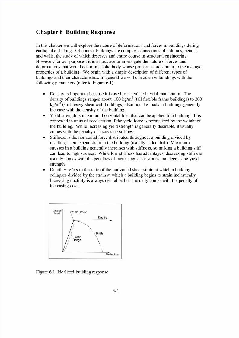
While steel MRF’s have the advantage that they are very flexible, that comes with thepenalty that they have very low lateral strength. Figure 6.6 shows a pushover analysis
(finite-element analysis by John Hall) of 20-story SMRF building that meets the 1992
UBC code for California. This analysis included numerous nonlinear effects on the
deformation of the steel, as well as also explicitly including the effect of howgravitational forces act on the building for large finite displacements. That is, when the
drift of the building becomes large, then every increasing lateral loads are put on thebuilding by gravity (kind of like the Tower of Pisa). This is known as the effect and
it is an important collapse mechanism for buildings.
P-∆
6-5
8/6/2019 Ch6 Buildings
http://slidepdf.com/reader/full/ch6-buildings 6/49
Figure 6.6 (from John Hall). Finite-element pushover analysis of a 20-story building thatmeets the 1992 US code standards for zone 4. P refers to the assumption that the moment
frame connections do not fracture, B assumes that weld fractures occur randomly at
stresses compatible with what was observe in the Northridge earthquake, and T assumesthat the welds had even less fracture resistance.
6-6

8/6/2019 Ch6 Buildings
http://slidepdf.com/reader/full/ch6-buildings 7/49
Figure 6.7. (from John Hall) Same as Figure 6.6., except for a 20 story steel fram
building that meets Japanese codes in place in the 1990’s. Notice the higher yieldstrength compared to the US building.
6-7

8/6/2019 Ch6 Buildings
http://slidepdf.com/reader/full/ch6-buildings 8/49
The curves U20P refer to a 20 story building that meets US 1992 zone 4 codes, and forwhich the welded moment resisting connections behave perfectly (no failures). The
curve that is designated as B refers to allowing failure of the moment resisting
connections assuming weld behavior consistent with observations in the 1994 Northridgeearthquake. T refers to the assumption of terrible performance of the welds. Notice that
weld failure significantly decreases both the yield strength and the ductility of thestructure. Also notice that a horizontal force of only 7% of the weight of the building isnecessary to push over a typical 20-story building in high seismic risk areas of the US.
Figure 6.7 shows a similar analysis, but it assumes that the building meets the building
code in force in Japan in the 1990’s. Japanese construction tends to put more emphasison the yield strength of a structure, and it is common that all connections in a Japanese
structure are moment-resisting connection (more costly than the US).
As it turns out, the code required yield strength tends to increase as building height both
increases and decreases from 20 stories. This is because design forces for wind loads
increase as the building becomes taller, whereas design forces for earthquakes decreaseas the building becomes taller (we’ll visit this later). So buildings shorter than 20 stories
are designed for earthquake loads and buildings taller than 20 stories are designed for
wind loads.
Figures 6.8 and 6.9 show the pushover analyses of 6-story steel moment resisting frame
buildings for 1990’s US and Japanese codes, respectively. Notice that the 6-story
buildings are required to have a greater yield strength than the 20 story buildings.
Moment resisting frame buildings can also be constructed with reinforced concrete beamsand columns. Concrete mrf’s have similar flexibility to steel mrf’s and the code
requirement for pushover yield strength is also similar. Both types of mrf’s are required
to have high ductility (approximately a factor of 10), but this is achieved in differentways with concrete. While steel is naturally ductile in tensional strain, unreinforced
concrete is naturally brittle in tension (it is very strong in compression however). Steel
reinforcing bars (rebar) are run longitudinally in concrete beams in order to greatlyincrease the tensional strength and ductility. While longitudinal rebar is very important,
it is not sufficient to make a beam adequately ductile. This was discovered through the
inspection of elements that failed in shear deformation in the 1971 San Fernando
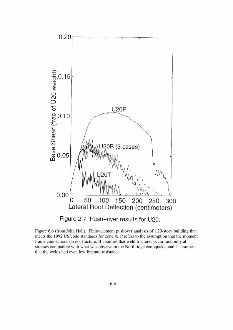
earthquake. An example of this type of failure is seen in Figure 6.10, which shows thefailure of a freeway bridge column during the 1994 Northridge earthquake. Notice that
the column originally fractured because of horizontal shear loads on the column. Once
the concrete in the column cracked, the concrete fell away from the column and theremaining rebar buckled into a mushroom shape. This is an example of non-ductile
concrete behavior. This deficiency was rectified by requiring spiral reinforcing bars that
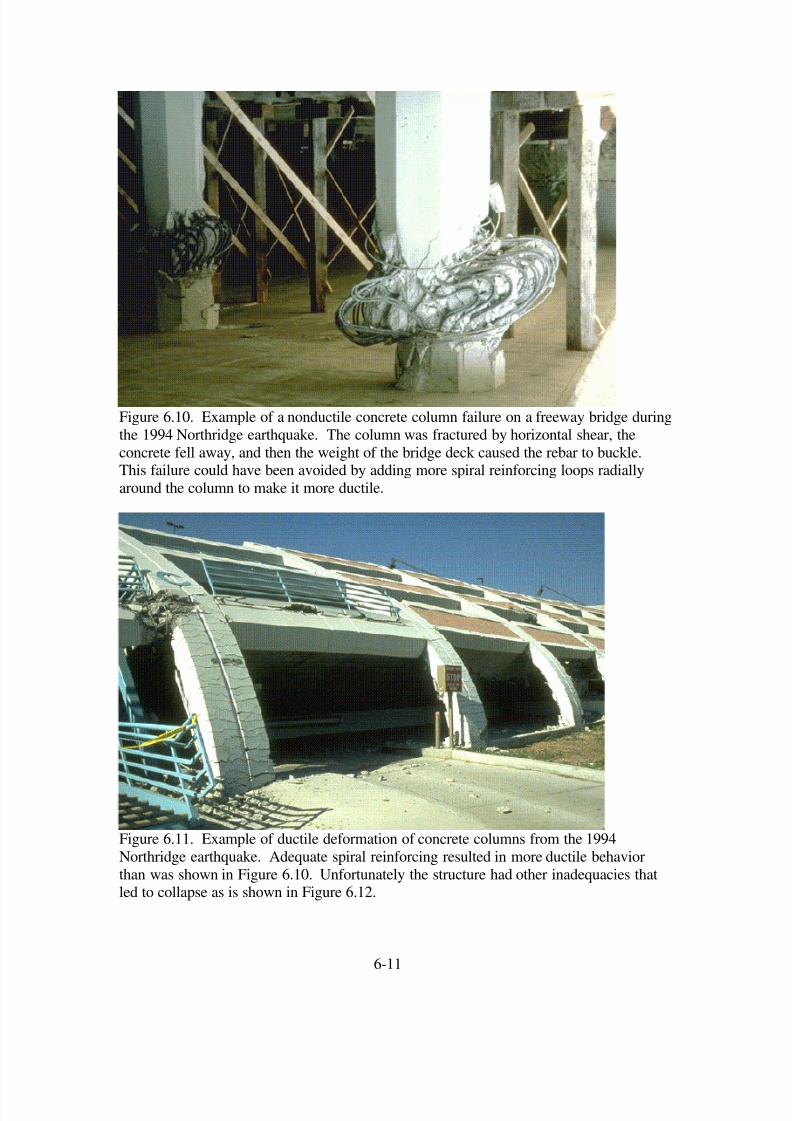
serves to confine the concrete to the beam, even if it is fracture. Figure 6.11 shows how aconcrete column can continue to carry significant loads even though it has been strained
well beyond its yield point. Unfortunately, this parking garage suffered significant
collapse because the elements of the building were insufficiently connected to each other.That is, the reinforcing bars must adequately tie the different elements together.
6-8

8/6/2019 Ch6 Buildings
http://slidepdf.com/reader/full/ch6-buildings 9/49
Figure 6.8 from John Hall. Same as Figure 6.6, but for US code 6-story steel frame
building.
6-9

8/6/2019 Ch6 Buildings
http://slidepdf.com/reader/full/ch6-buildings 10/49
Figure 6.9 from John Hall. Same as Figure 6.6, but for Japanese code 6-story steel frame
building
6-10
8/6/2019 Ch6 Buildings
http://slidepdf.com/reader/full/ch6-buildings 11/49
Figure 6.10. Example of a nonductile concrete column failure on a freeway bridge during
the 1994 Northridge earthquake. The column was fractured by horizontal shear, the
concrete fell away, and then the weight of the bridge deck caused the rebar to buckle.This failure could have been avoided by adding more spiral reinforcing loops radially
around the column to make it more ductile.
Figure 6.11. Example of ductile deformation of concrete columns from the 1994
Northridge earthquake. Adequate spiral reinforcing resulted in more ductile behavior
than was shown in Figure 6.10. Unfortunately the structure had other inadequacies thatled to collapse as is shown in Figure 6.12.
6-11

8/6/2019 Ch6 Buildings
http://slidepdf.com/reader/full/ch6-buildings 12/49
Figure 6.12. Despite the ductile behavior of the concrete columns, this parking structurecollapsed because the floor slabs were not adequately connected to the rest of the
structure. That is, the beams and columns were ductile, but the connections between
these elements were not.
Non-ductile concrete frame buildings are recognized as a class of particularly dangerous
structures. They have the particularly bad combination of having a low yield stress
combined with a low ductility (they’re brittle). The tremendous loss of life in the 1999Izmet Turkey earthquake was an example on non-ductile concrete frame failure. These
failures are often very disastrous since the building often pancakes into a pile of floor
slabs (very nasty). Figure 6.13 shows an example of the remains of an 8-story non-ductile concrete frame building that collapse in Mexico City in the 1957 Acapulco
earthquake. Many concrete moment resisting frame buildings that were constructed in
the United States prior to 1975 can also be classified as non-ductile concrete frames.Failures in the 1971 San Fernando earthquake resulted in a building code change in 1975
that significantly enhanced the ductility of buildings built after 1975. Unfortunately,there are no ordinances that force a building owner to strengthen these buildings.Furthermore, most of the occupants of these buildings are not aware of the potential
deficiencies of their building.
6-12

8/6/2019 Ch6 Buildings
http://slidepdf.com/reader/full/ch6-buildings 13/49
Figure 6.13. Collapse of an 8-story non-ductile concrete moment resisting frame building
in Mexico City from the 1957 Acapulco earthquake.
Braced Frame Structures
The lateral yield strength of a building can be increased by adding diagonal braces to a
structure, as is shown in Figure 6.13. While diagonal braces increase the yield strength,
they also increase the stiffness of a building. That is, there is a trade-off between thedesired trait of high strength and the undesired trait of high stiffness. Furthermore, it can
be difficult to make a braced frame that has high ductility. This is because the use of large bracing elements tends to result in very stiff braces that apply very large loads to
their connections with the structure, thereby concentrating damage at these connections.
However, the use of small diameter bracing elements can end up with braces that tend tohave ductile extension, but they buckle in compression. As a building undergoes cyclic
loading, small braces become ineffectual, since they permanently extend and buckle (see
Figure 6.14). Caltech’s Broad Center is one of the first buildings in the United States to
use new style of brace called an unbonded brace. This consists of a small diameter steelbrace that is jacketed in a concrete liner. There is a lubricating element between the
concrete and the steel. The concrete jacket prevents the brace from buckling incompression and hence this brace is ductile in both extension and compression. Figure6.15 shows an example of Broad Center’s unbonded brace.
6-13

8/6/2019 Ch6 Buildings
http://slidepdf.com/reader/full/ch6-buildings 14/49
Figure 6.13. Example of a braced steel-frame.
Figure 6.15 Large braces are stiff and they put large loads into a frame, but small braces
can buckle in compression.
6-14

8/6/2019 Ch6 Buildings
http://slidepdf.com/reader/full/ch6-buildings 15/49
Unbonded Brace in the Broad Center
Figure 6.14. Broad Center unbonded brace. The steel is ductile in tension and
compression since it is jacketed by concrete (yellow) to prevent buckling in compression.
Wood-Frame Structures
Wood frame is the most common type of construction in California; most residences and
many commercial structures are in this category. Since wood is thought of as a “flexible”
material, you might think of a very flexible building when you think of a wood frame
structure. This would be a mistake. In fact, most wood frame construction is extensivelybraced. Furthermore, continuous plywood panels, and sheetrock panels are typically
fastened to either side of the wooden framing. Such walls may be best described as shear
panels. These panels are geometrically connected into rectangular box shapes. In thissense, most wood frame construction might be better described as a shell type of
structure. Another feature of wood frame construction is that the structure is relativelylight (the dead load) compared with the weight of the contents (the dead load). Since it is
not feasible to allow the structure to deform significantly because of the live loads (the
plaster would crack), wood frame structures tend to be extremely strong (and stiff)compared to their weight. They are also relatively ductile (the framing is redundant, and
nails must be pulled out to disconnect elements). As a result of these features, wood
frame structures tend to perform very well in earthquakes. Despite the fact that thesestructures have been located in areas of violent shaking in past earthquakes, collapse of
these structures is exceedingly rare. Figure 6.15 shows the Turnagain Heights housing
development (wood frame) following the 1964 Alaskan Earthquake. Despite thetremendous damage caused by a massive landslide beneath the development, the woodframe houses essentially remained intact.
6-15

8/6/2019 Ch6 Buildings
http://slidepdf.com/reader/full/ch6-buildings 16/49
1964 Alaska Earthquake, Turnagain Heights
Figure 6.15. Wood frame houses that rode through the massive landslide triggered by the1964 Alaskan earthquake.
Unreinforced Masonry
In the earlier part of the 20th
Century, many buildings were constructed of unreinforcedbrick; that is the exterior walls are several courses of brick and mortar, whereas the inner
walls, floors, and roof are wood frame construction. The exterior brick walls in this typeof construction tend to be heavy and brittle. That is, the walls cannot sustain tension.
URM’s have the undesirable characteristics that they are heavy, stiff, and quite brittle.
The inadequacies of unreinforced masonry (URM) became obvious in the 1933 LongBeach earthquake and many municipalities adopted building codes (between the mid
1930’s and 1950, depending on the city) that required that these masonry construction
buildings should be reinforced with steel. However, several cities have numerous
examples of these historic structures. Following serious damage to URM’s in the 1971San Fernando earthquake, the cities of Los Angeles and Long Beach adopted
controversial legislation that required that all URM should have some strengthening. At
a minimum, this involved making stronger connections between the wooden floor trussesand the brick walls. This tends to decrease the bending moments on the base of the brick
walls for out-of-plane shaking. Some buildings are also reinforced by building another
structural system (often steel) within the building. Although strengthened URM are an
6-16
8/6/2019 Ch6 Buildings
http://slidepdf.com/reader/full/ch6-buildings 17/49
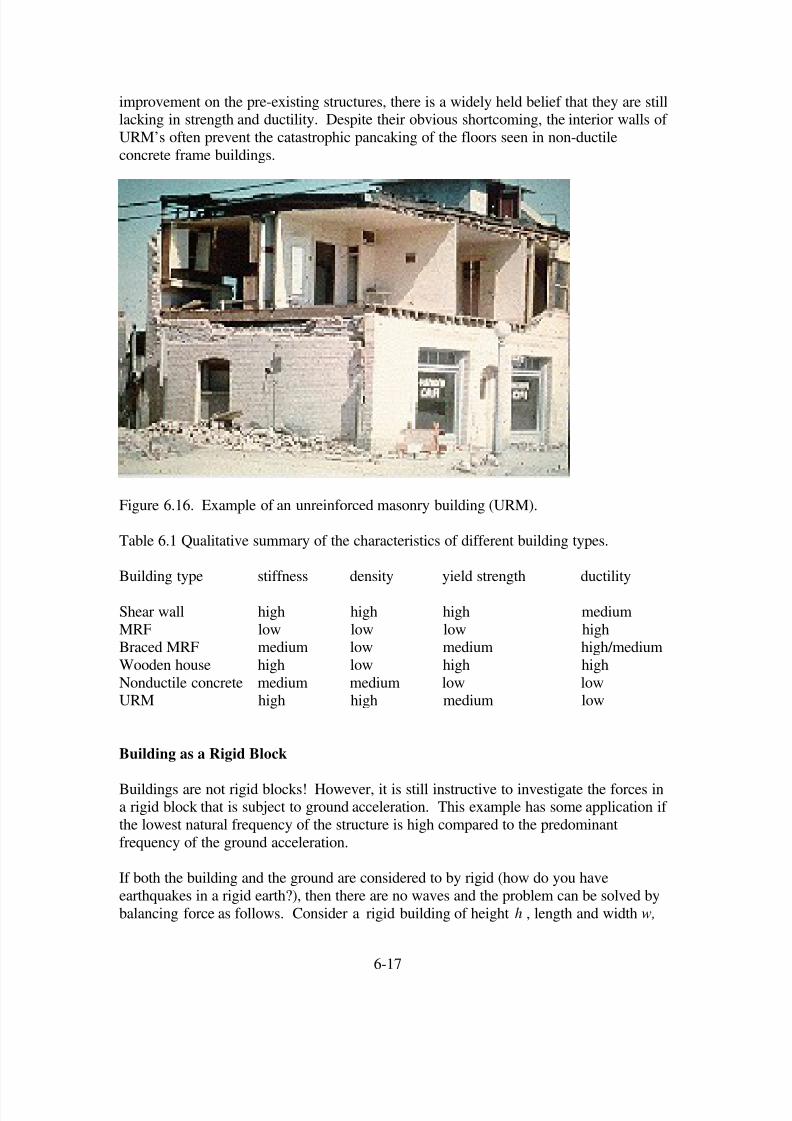
improvement on the pre-existing structures, there is a widely held belief that they are stilllacking in strength and ductility. Despite their obvious shortcoming, the interior walls of
URM’s often prevent the catastrophic pancaking of the floors seen in non-ductile
concrete frame buildings.
Figure 6.16. Example of an unreinforced masonry building (URM).
Table 6.1 Qualitative summary of the characteristics of different building types.
Building type stiffness density yield strength ductility
Shear wall high high high medium
MRF low low low highBraced MRF medium low medium high/medium
Wooden house high low high high
Nonductile concrete medium medium low lowURM high high medium low
Building as a Rigid Block
Buildings are not rigid blocks! However, it is still instructive to investigate the forces ina rigid block that is subject to ground acceleration. This example has some application if
the lowest natural frequency of the structure is high compared to the predominant
frequency of the ground acceleration.
If both the building and the ground are considered to by rigid (how do you have
earthquakes in a rigid earth?), then there are no waves and the problem can be solved by
balancing force as follows. Consider a rigid building of height h , length and width w,
6-17

8/6/2019 Ch6 Buildings
http://slidepdf.com/reader/full/ch6-buildings 18/49
and average density ρ be subjected to a horizontal acceleration ( )u t as shown in Figure
6.17.
Figure 6.17. Forces acting on a rigid rectangular building that is sitting on a rigid earth.
There are both shear stresses to horizontally accelerate the building, and also a moment
that is applied to the base to keep the building from rotating.
The total momentum of the building can be considered to be the sum of the translation of the center of mass of the building and also the rotational momentum of the building about
an axis running through the center of the building. Since the ground is considered as
rigid, the building cannot rotate and the translational momentum of the building is just
( ) ( )2
1P t hw u t ρ = (6.1)
where is the momentum in the( )1P t
1 x direction (that’s all there is in this problem). The
total horizontal force on the bottom of the building is
( ) ( ) ( )2
1 1F t P t hw u t ρ = = (6.2)
Therefore the shear stress on the bottom of the building is just the force divided by the
cross sectional area, or
( ) ( )13 t huσ ρ = t (6.3)
So the shear stress at the bottom of a rigid building on a rigid earth just depends on the
ground acceleration and the height of the building (assuming that the density is constant).However, there is more to this simple problem. The shear stress at the bottom of the
building would cause the building to rotate if there were no counteracting forces on the
base of the building. That is the total moment applied to the base of the building must bezero, or
6-18

8/6/2019 Ch6 Buildings
http://slidepdf.com/reader/full/ch6-buildings 19/49
( ) ( )2
1 33 1 1
2
,2
w
w
hF t w t x gh x dxσ ρ
−
− −⎡ ⎤⎣ ⎦∫ 10= (6.4)
where we assumed that the normal force on the base of the building consists of the weight
of the building plus a moment that keeps the building form rotating. If we assume thatthe normal stress consists of constant compressional stress from the weight of the
building ( )gh ρ plus another stress that varies linearly with distance along the base then
( ) ( )33 1 1 1, x t c t x gh w x wσ ρ = + − < < (6.5)
where is now only a function of time. In this case( )c t
( ) ( )2
2
1 1
2
02
w
w
hF t wc t x dx
−
1− =∫ (6.6)
Substituting (6.2) into (6.6) and performing the integration yields( )
( )2 2 4
02 12
h w u t wc t
ρ − =
(6.7)
or
( ) ( )2
33 1 1 1, 6h
x t gh x u t w xw
σ ρ ρ ⎛ ⎞
= + − < <⎜ ⎟⎝ ⎠
w (6.8)
Therefore the normal stresses at the outer edges of the building are
( ) ( )
( )
2
33 1, 3
3
h x w t gh wu t
w
hh g u t w
σ ρ ρ
ρ
⎛ ⎞= ± = ± ⎜ ⎟
⎝ ⎠
⎡ ⎤⎛ ⎞= ± ⎜ ⎟⎢ ⎥⎝ ⎠⎣ ⎦
(6.9)
There are cases where engineering materials fail easily in tension. Tensional stresses inour rigid building occur at the outer edge when
3
wu g
h> (6.10)
Therefore, rigid buildings that are tall compared with their width can result in tensional
stresses in the exterior part of the building.
If we can approximately model the dynamics of a building with a rigid block, then the
stresses in the building are determined by the peak acceleration. However, it has been
long known that the peak accelerations observed in earthquakes are considerably larger
than the nominal lateral strength of buildings that have survived those groundaccelerations. As it turns out, the peak acceleration in most seismic records is strongly
dependent on high-frequency parts of the motion (typically > 3 Hz), and the assumption
that the building’s fundamental frequencies are large compared to the ground accelerationdoes not apply.
6-19
8/6/2019 Ch6 Buildings
http://slidepdf.com/reader/full/ch6-buildings 20/49
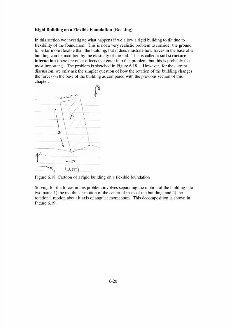
Rigid Building on a Flexible Foundation (Rocking)
In this section we investigate what happens if we allow a rigid building to tilt due to
flexibility of the foundation. This is not a very realistic problem to consider the groundto be far more flexible than the building, but it does illustrate how forces in the base of a
building can be modified by the elasticity of the soil. This is called a soil-structureinteraction (there are other effects that enter into this problem, but this is probably themost important). The problem is sketched in Figure 6.18. However, for the current
discussion, we only ask the simpler question of how the rotation of the building changes
the forces on the base of the building as compared with the previous section of thischapter.
Figure 6.18 Cartoon of a rigid building on a flexible foundation
Solving for the forces in this problem involves separating the motion of the building intotwo parts; 1) the rectilinear motion of the center of mass of the building, and 2) the
rotational motion about it axis of angular momentum. This decomposition is shown in
Figure 6.19.
6-20

8/6/2019 Ch6 Buildings
http://slidepdf.com/reader/full/ch6-buildings 21/49
Figure 6.19 The motion rigid building can be viewed as the sum of a translation of the
center of mass together with a rotation about the principal axis of inertia.
Let be the motion of the base of the building in an inertial frame, be the
linear motion of the center of mass, and
( )u t ( ) xu t
( )u t θ be the motion of the base due to pure
rotation of the building about the center of rotation which is located at the midpoint of thebuilding. Then
( ) ( ) ( ) xu t u t u t
θ = + (6.11)
and
( ) ( ) ( ) xu t u t u t
θ = + (6.12)
now
( ) ( ) ( )sin2 2
h hu t t t θ θ θ θ = ≈ π (6.13)
then
( ) ( )2
hu t t θ θ ≈ (6.14)
The force system on the base of the building can be considered to be the sum of the a
horizontal force ( )1F t (these are unbalanced) and a resisting moment ( ) M t caused by
the distribution of vertical stresses on the base of the building. The rectilinear
momentum of the building ( )P t is just
( ) ( ) ( ) ( ) ( )23 3
0
12 2
h
P t w u t x t dx m u t h t ρ θ ⎛ ⎞ ⎛
= − = −⎜ ⎟ ⎜⎝ ⎠ ⎝ ∫ 1 θ ⎞⎟ ⎠
(6.15)
where is just the mass of the building. The force on the base of the building is
then
2m hw ρ =
( ) ( ) ( ) ( )1
1
2F t P t m u t h t θ
⎛ = = −⎜
⎝ ⎠
⎞⎟ (6.16)
6-21

8/6/2019 Ch6 Buildings
http://slidepdf.com/reader/full/ch6-buildings 22/49
The shear stress on the base of the building is then
( )( ) ( )
( ) ( )1
13 2 2
1
2
F t P t t h u t
w wσ ρ
⎛ = = = −⎜
⎝ ⎠
h t θ
⎞⎟ (6.17)
At this point, we do not yet know the shear stress, since we do not know . We can
calculate the rotation of the building as follows, ( )t θ
( ) ( ) ( )12
h M t F t I t θ + = (6.18)
where
( 2 21
12) I m h w= + (6.19)
Combining (6.16), (6.17), and (6.19) yields
( )( )
( ) ( )2 2
12
24
mht M t
m h wθ u t
⎡ ⎤= +⎢ ⎥+ ⎣ ⎦
(6.20)
Now the moment at the base of the building is
( ) ( )2
33 1 1
2
w
w
M t w t x dxσ −
= ∫ (6.21)
If we assume that the normal stress is proportional the vertical deflection, then
( ) ( )33 1 12wt k t x xσ θ = − <
2w< (6.22)
where k is a type of stiffness with units of stress per unit of displacement ( it differs from
a regular spring constant, which has units of force per unit displacement) . Therefore,
( ) ( ) ( )2
2 4
1 1
2
1
12
w
w
M t wk t x dx w k t θ
−
= =∫ θ (6.23)
Combining (6.20) and (6.23) gives us the equation for a single degree of freedom forced
oscillator
( )( )
( )( )
( )4
2 2 2 2
6
4 4
kw ht t
m h w h wθ θ − =
+ + u t (6.24)
We immediately recognize that this is an un-damped forced linear oscillator with anatural period of
2
0 2 2
1
4
k w
h w mω =
+(6.25)
The full solution to this force oscillator is given in Chapter 1 (see equation 1.40 withdamping equal to zero) as
( )( )
( ) ( ) 0
2 20
sin6
4
t ht u t H t
h w
ω θ
ω
⎡ ⎤= ∗ ⎢ ⎥
+ ⎣ ⎦ (6.26)
While we have modeled the building as an un-damped SDOF, the full solution to this
problem is quite complex, since the oscillations of the building would excite waves in the
elastic medium. The excitation of the waves would cause kinetic energy in the building
6-22
8/6/2019 Ch6 Buildings
http://slidepdf.com/reader/full/ch6-buildings 23/49
to be radiated as wave energy into the surrounding medium. This would be a form of
radiation damping of the oscillations of the building. Substituting (6.26) into (6.17) gives
( ) ( )( )
( ) ( )
( ) ( ) ( )
2 2
013 22 2
0
2 2
022 2 2
sin3
4
3sin
4
t ht h u t u t H t
t h w
h mhu t t H t t
k t w h w
ω σ ρ
ω
ρ δ ω
⎛ ⎞⎡ ⎤∂⎜ ⎟= − ∗ ⎢ ⎥⎜ ⎟∂+ ⎣ ⎦⎝ ⎠
⎛ ⎞∂= ∗ − ⎡ ⎤⎜ ⎟⎣ ⎦⎜ ⎟∂+⎝ ⎠
(6.27)
We can also calculate the vertical compressive stresses at the outer edges of the building
by substituting (6.26) into (6.22).
( ) ( )
( )( ) ( )
( ) ( )
33 1
0
2 20
02 2
;
sin6
4
6
sin4
t x w gh kw t
t hgh kw u t H t
h w
h
gh mku t H t t w h w
σ ρ θ
ω ρ
ω
ρ ω
= ± = ±
⎡ ⎤= ± ∗ ⎢ ⎥
+ ⎣ ⎦
= ± ∗ ⎡ ⎤⎣ ⎦+
(6.28)
These are fairly complex relationships. However, we can get some idea of the effect of
building tilting by investigating the initial response of the building to a impulse in
acceleration, . In this case (6.27) becomesmax
u
( ) ( )( )
( ) ( )
( )
( )( ) ( )
( )( )
( ) ( ) ( )
( )
2 2
013 max 22 2
0
2
0max 02 2
0
2
0max 0 02 2
0
2
max
sin3
4
sin3cos
4
sin32 cos sin
4
61
4
I t ht hu t t H t
t h w
t hhu t t H t t
t h w
t hhu t t t t H t t
h w
hhu t
h
ω σ ρ δ δ
ω
ω ρ δ δ ω
ω
ω ρ δ δ δ ω ω ω
ω
ρ δ
⎛ ⎞⎡ ⎤∂⎜ ⎟= − ∗ ⎢ ⎥⎜ ⎟∂+ ⎣ ⎦⎝ ⎠
⎛ ⎞⎡ ⎤∂⎜ ⎟= − +⎢ ⎥
⎜ ⎟∂+ ⎣ ⎦⎝ ⎠⎛ ⎞
0
⎡ ⎤⎜ ⎟= − + −⎢ ⎥⎜ ⎟+ ⎣ ⎦⎝ ⎠
= −
( )( )0 max 0 02 2
cos sint hu H t t w
ω ρ ω ω ⎛ ⎞⎜ ⎟ −⎜ ⎟+⎝ ⎠
(6.29)
Or we can write the shear response for an arbitrary acceleration as
( ) ( ) ( ) ( ) ( )
2
13 0 0 02 2
6
1 cos sin4
I h
t hu t t hu t H t t h wσ ρ ω ρ ω ω
⎛ ⎞
⎜ ⎟= − − ∗⎜ ⎟+⎝ ⎠ (6.30)
Therefore, the shear maximum shear stress is decreased for a rocking building compared
with a rigid building (that is, for an impulse of acceleration). To fully understand theeffect of this rocking, we would have to know the actual ground acceleration time history.
If the ground motion was harmonic with the same period as the natural frequency of
rocking, then the rocking building would resonate with the ground. If the duration of the
6-23
8/6/2019 Ch6 Buildings
http://slidepdf.com/reader/full/ch6-buildings 24/49
ground motion was large enough, then the rocking building would develop even larger
shears than the rigid building on the rigid foundation.
Notice that the acceleration impulse response for the outer edges of the building can bederived from (6.28), and is
( ) ( ) ( )
( ) ( )
33 1 max 02 2
02 2
6; s4
6sin
4
ht x w gh mku t H t t w h w
hgh mku t H t t
w h w
inσ ρ δ
ρ ω
= ± = ± ∗ ω ⎡ ⎤⎣ ⎦+
= ± ∗ ⎡ ⎤⎣ ⎦+
(6.31)
Notice that as , a very, very flexible foundation, then0k →
( )33 1 0;t x w gh t σ ρ = ± = ω (6.32)
That is, as the foundation becomes more flexible, the normal stresses on the columns
decrease. However, depending on the convolution term, there may be resonances and thecompressive stresses may actually increase.
Flexible Building as a Continuous Cantilevered Beam
The problem of the dynamic motions of a continuous prismatic beam can give us some
insight into the deformation of buildings. To solve such a cantilevered beam problem infull generality is exceeding complex. To begin with we recognize that, if the building is
considered as a continuum, it would often be anisotropic. For example, consider an mrf.
The stiffness associated with inter-story drift ( )13 23andε ε would be much less than the
stiffness associated with shearing the actual floor slabs12ε . Likewise the stiffness
associated with extension along columns ( )33ε is different than for extension along the
floor slabs ( )11 22andε ε . However, we will assume that only parts of the strain tensor
which are important to describe the deformation of the building are inter-story shear
strain and extensional strain along the columns. We can thus approximate the building as
being isotropic, since the other elastic moldulii are not important. We must alsorecognize that the material in our imaginary continuous beam may have a very unusual
Poisson’s ratio. That is, the building is very stiff in compression along the columns and
very flexible in inter-story shear. That is, λ µ . In fact, for a tall mrf (either concrete
or steel), the velocity of P-waves up the building is 10 to 20 times more than the S-wavevelocity.
While the complete solution for an isotropic elastic cantilevered beam is itself quite
complex, there are two end-member cases where the solution is more tractable (see figure
6.20).
6-24

8/6/2019 Ch6 Buildings
http://slidepdf.com/reader/full/ch6-buildings 25/49
The first is the case in which the height of the building is large compared to the height (a
tall skinny building). In this case the building deforms primarily by bending which is the
term used for extensional strains in the columns (extension and compression at the
opposite sides of the building). There is a well developed theory (the technical theory of bending) which allows beam problems to be solved with the assumption that the shear
strains are approximately zero. This is called a bending beam. The stiffness of abending beam is determined by its flexural rigidity, EI , which scales with dimension as
2
1 1 2
0 03
w w E 4
EI x dx dx w= =∫ ∫ (6.33)
where E is the Young’s modulus and the building is assumed to have a square cross
section of width w. The building becomes very stiff against flexure as w becomes large.
In the second case the building is assumed to be much wider than it is tall. When the
ground beneath the building moves horizontally, this is identical to the problem of havingan SH wave propagate vertically in a layer of building; the bending is approximately zero
in this case. This is called a shear beam. In this case the total stiffness against shear is
just the shear modulus times the cross sectional area ( )2wµ . Therefore, it is easy to see
why a wide building is dominated by shear and not by bending.
While actual buildings are neither a true bending beam nor a shear beam, we can gainsome useful insight by looking at these approximate modes of deformation.
Figure 6.20. Cartoon on the left is a bending beam (negligible inter-story shear strains).
Most of the deformation occurs because of compression and extension of the outer
columns. Cartoon on the right is a shearing beam (negligible extension/compression onthe columns). The floor slabs remain horizontal.
6-25
8/6/2019 Ch6 Buildings
http://slidepdf.com/reader/full/ch6-buildings 26/49
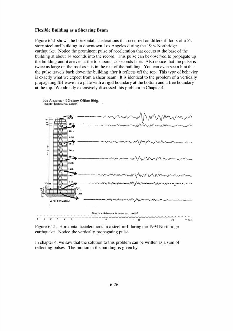
Flexible Building as a Shearing Beam
Figure 6.21 shows the horizontal accelerations that occurred on different floors of a 52-
story steel mrf building in downtown Los Angeles during the 1994 Northridgeearthquake. Notice the prominent pulse of acceleration that occurs at the base of the
building at about 14 seconds into the record. This pulse can be observed to propagate upthe building and it arrives at the top about 1.5 seconds later. Also notice that the pulse istwice as large on the roof as it is in the rest of the building. You can even see a hint that
the pulse travels back down the building after it reflects off the top. This type of behavior
is exactly what we expect from a shear beam. It is identical to the problem of a verticallypropagating SH wave in a plate with a rigid boundary at the bottom and a free boundary
at the top. We already extensively discussed this problem in Chapter 4.
Figure 6.21. Horizontal accelerations in a steel mrf during the 1994 Northridge
earthquake. Notice the vertically propagating pulse.
In chapter 4, we saw that the solution to this problem can be written as a sum of
reflecting pulses. The motion in the building is given by
6-26
8/6/2019 Ch6 Buildings
http://slidepdf.com/reader/full/ch6-buildings 27/49
( ) 3 31 3 1 1 1
3 31 1
2 2,
4 4....
g g g
g g
3 x x xh hu t x u t u t u t
c c c c
x xh hu t u t
c c c c
⎛ ⎞ ⎛ ⎞ ⎛ = − + − + − − −⎜ ⎟ ⎜ ⎟ ⎜
⎝ ⎠ ⎝ ⎠ ⎝
⎛ ⎞ ⎛ ⎞− − + + − − +⎜ ⎟ ⎜ ⎟
⎝ ⎠ ⎝ ⎠
c
⎞⎟ ⎠
(6.34)
where c is the shear-wave velocity in the building and ( )1
g
u t is the horizontal motion of the ground at the base of the building. Notice that this sequence repeats with periodicity
4h
c, which is the fundamental period of the building oscillation. We are particularly
interested in the drift in the building13
ε , which we can calculate from (6.34).
( ) 3 313 3 1 1 1
3 31 1
1 2,
4 4....
g g g
g g
32 x x xh ht x u t u t u t
c c c c c
x xh hu t u t
c c c c
ε ⎡ ⎛ ⎞ ⎛ ⎞ ⎛
= − − + − + + − −⎜ ⎟ ⎜ ⎟ ⎜⎢⎝ ⎠ ⎝ ⎠ ⎝ ⎣
⎤⎛ ⎞ ⎛ ⎞− − + − − − +⎜ ⎟ ⎜ ⎟ ⎥
⎝ ⎠ ⎝ ⎠ ⎦
c
⎞⎟ ⎠
(6.35)
We as especially interested in the drift at the base of the building ( )3 0 x = , or
( ) ( )13 1 1 1
1 2 42 2 ....b g g gh h
t u t u t u t c c
ε ⎡ ⎤⎛ ⎞ ⎛ ⎞
= − + − − − +⎜ ⎟ ⎜ ⎟⎢ ⎥⎝ ⎠ ⎝ ⎠⎣ ⎦
c(6.36)
That is at the base of the building, the up- and down-going waves interfere destructively
to give zero displacement (remember it’s a rigid base), but the associated strains interfereconstructively to give twice as large a drift. Notice that the drift at the top of the building
is zero, even though the motion is twice as large as in the rest of the building.
The actual drift in the base of our shear beam depends on the nature of the ground
velocity . Although strong shaking in earthquakes can take a wide variety of forms,
it is common that ground displacements near large ruptures have motions described by a
pulse of displacement (sometimes referred to as the “killer pulse”), or in other cases they
may be dominated by the permanent offset of the ground with respect to an inertialreference frame. Consider the simple ground motions shown in Figure 6.22. The ground
accelerations consist of a sequence of positive and negative constant steps. This results
in ground velocity that consists of a number of linear ramps. The solution to this problemis simple as long as the duration of the pulse is shorter than the time required for the wave
to travel up the building and then return
( )1u t
2h
c
⎛ ⎜⎝ ⎠
⎞⎟ . Things get more complex when the
duration of the ground motion becomes large. Of interest is the maximum shear strain at
the base of the building, which we can write as
max13 max
gbu
Ac
ε =
(6.37)
where A is an amplification factor. For ground motions A and B, A depends on1 pT T ,
where1
4T h= c is the fundamental period of the building. The factor A reaches 2 for
ground motion A (when ) and 4 for ground motion B (when ). Plots of 1 pT T ≤
1 pT T =
6-27
8/6/2019 Ch6 Buildings
http://slidepdf.com/reader/full/ch6-buildings 28/49
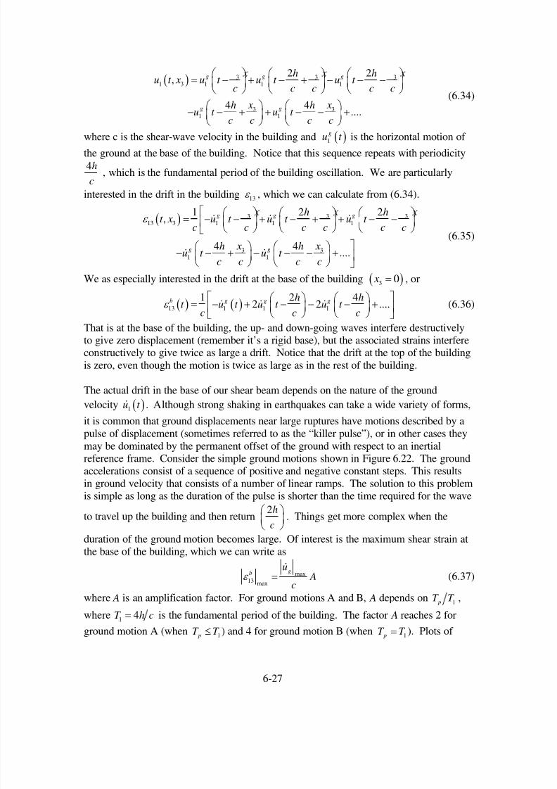
( )13
b t ε for are shown in Figure 6.23. The configurations of the building at
different times are shown in Figure 6.24.
1 pT T =
Figure 6.22. Simple ground motions that consist of a simple static displacement (case A)and a pulse of displacement (case B).
6-28

8/6/2019 Ch6 Buildings
http://slidepdf.com/reader/full/ch6-buildings 29/49
Figure 6.23. Shear strain in the base of the building. One unit on the vertical axis
corresponds to a strain of ( )13
max
b
g
c t
u
ε
.
Figure 6.24. Configuration of a multi-story building at time intervals of 4 pT for the
case . a) Elastic shear beam building for ground motion A. b) Elastic shear beam
building for ground motion B. c) Inelastic shear beam building for ground motion B(qualitative depiction).
1 pT T =
6-29

8/6/2019 Ch6 Buildings
http://slidepdf.com/reader/full/ch6-buildings 30/49
The shear strain 13 max
bε can be large enough to be well into the inelastic range. With
max1m sg
u = , and 100m sc = (a typical value for a tall building), we can use (6.37) and
Figure 6.23 to calculate that 13 max0.02bε = for ground motion A and 0.04 for ground
motion B, when . These are large values and can greatly exceed the yield strain atthe base of the building (e.g., check out Figure 6.6).
1 pT T =
The dynamics problem becomes far more complex when the building experiences
yielding. That is the governing equations are no longer linear and it is generallynecessary to perform a careful finite-element analysis to understand the deformation of
the structure. Such an analysis was performed by Hall and others (1995), and the typical
results are shown in Figure 6.25. Figure 6.26 shows the location of weld failures(moment resisting connections) in the structure.
When the building yields, it tends to develop a permanent bend in the structure. Once a
tall frame building is permanently bent, there is really no practical way to straighten itagain, and it is a total loss. Furthermore, if the bending exceeds several percent locally,
then there may be a real fear of collapse due to P-∆ effects.
Figure 6.25 From Hall and others (1995).
One way to gain some insight into the behavior or a yielding beam is to consider the
building as if it were linear, but with a local stiffness that changes with the amplitude of
the local drift. For example, the slope of the force-drift curve in Figure 6.6 is called the
6-30

8/6/2019 Ch6 Buildings
http://slidepdf.com/reader/full/ch6-buildings 31/49
tangent stiffness, and it rapidly decreases when the building begins to yield (it even
changes sign). Since the stiffness is critical in determining the velocity at which a
deformation propagates up a building, loss of stiffness due to yielding means thatdeformations tend to slow their propagation up a building. That is, once yielding begins,
deformations tend to localize in these yielding zones. Perhaps an example of this is
shown in Figure 6.27 in which an 8-story building lost the 6
th
story during the 1995 Kobeearthquake. That is, when ground motions are propagating in a building, then onceyielding begins at a particular place, then that is where the majority of the strain will
occur.
Figure 6.26 Distribution of weld fractures in a 20 story building caused by a 2 meter
displacement pulse as reported by Hall and others (1995). A dark triangle locates acracked column-flange weld at a column splice due to tension in the column. These canbe very serious, since if the column separates in tension, but does not come back together
properly, the column may fail to carry the weight of the building (very bad). Open
triangles locate failed moment-frame connections, which causes a loss of ductility, but isnot as serious as failure of a column splice.
6-31

8/6/2019 Ch6 Buildings
http://slidepdf.com/reader/full/ch6-buildings 32/49
Figure 6.27. Once yielding begins at some location, then the loss of stiffness at that
location can tend to localize the deformations to that location. This may have been thecause of the collapse of the 6th floor of this 8-story building in Kobe in 1995.
Prediction of the collapse of structures is extremely difficult. That is, the failure of acritical component (such as a weld) may cause loads carried by a structural element to be
transferred to others structural elements, which may cause a cascade of failures.
Assessing the likelihood of failure means obtaining an accurate understanding of all of
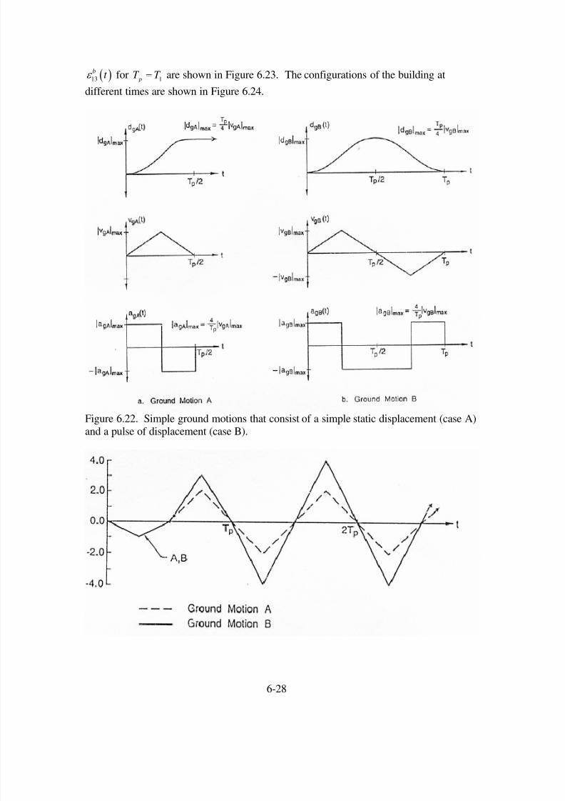
these interrelations (highly nonlinear and perhaps chaotic). Consider the three identical21-story steel mrf towers in Mexico City that experienced the 1995 Michoacanearthquake (Figure 6.28 and 6.29). This was not a failure due to the propagation of a
displacement pulse. Instead, it was due to amplification of 2-second ground motions by
the shallow sediments beneath Mexico City (see Chapter 4).
Although the three towers were designed to be the same, their behavior was quite
different, despite their close proximity to each other. The tower on the right suffered no
apparent damage as a result of the shaking. The tower on the left collapsed, while thetower in the middle had a permanent roof drift of about 1 meter. It would be very
difficult to explain this difference by current state of the art in numerical modeling of
these buildings.
6-32
8/6/2019 Ch6 Buildings
http://slidepdf.com/reader/full/ch6-buildings 33/49
Figure 6.28 Three 21-story steel mrf’s that were designed to be identical. The left tower
collapsed, the middle tower had a 1-meter permanent drift of its roof, and the right towersuffered no apparent damage. (Mexico City following the 1985 Michoacan earthquake).
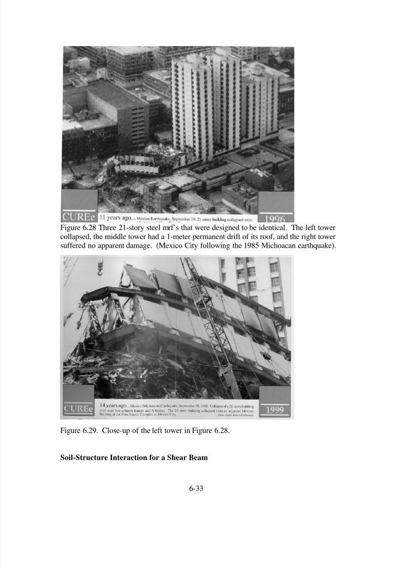
Figure 6.29. Close-up of the left tower in Figure 6.28.
Soil-Structure Interaction for a Shear Beam
6-33

8/6/2019 Ch6 Buildings
http://slidepdf.com/reader/full/ch6-buildings 34/49
As long as we are treating the shear-beam building as if it was a low-velocity, low-
density layer on the top of the Earth, we can gain some insight into how the building
interacts with the soil layers. For instance, we can ask 1) how much does the presence of the building change the ground motion at its base compared to the ground motion that
would have occurred without the presence of the building (a free field site), and 2) how
much of the motion of the building is transmitted through the base of the building when awave reflects off the top of the building and then transmits through the base of thebuilding?
From Chapter 4 we know that for an SH-wave vertically incident on a the base of a layerof buildings,
2
2
22 1 ...
T
G B B
I
G G B B G
B B B B B B
G G B B G G G G
A
A
µ β
µ β µ β
β ρ β ρ β ρ
β ρ β ρ β ρ β ρ
=+
⎡ ⎤⎛ ⎞⎢ ⎥= ≈ − + ⎜ ⎟
++
⎢ ⎥⎝ ⎠⎣ ⎦
(6.38)
where T
B A is the amplitude of the wave transmitted into the building and I
G A is the
amplitude of the incident wave from the ground. Let us suppose that the shear wavevelocity in the soil is approximately twice that in the building (a fairly soft soil), and that
the density of the building is 5% of the density of the soil, then
( )2 1 0.025 1.975T
B
I
G
A
A≈ − = (6.39)
But the amplitude of the motion without the building is 2.0 because it is an SH reflection
off of the free surface. Therefore the building causes the amplitude of the motion to bedecreased by 1 ¼ % relative to the ground motion that would have occurred without the
presence of the building. This soil-structure interaction effect seems to be far less
important than the effect of allowing the building to rock on its foundation.
We can also compute the size of the wave reflected off the base of the building R
B A
compared with the amplitude of the downgoing wave in the building I
B A . That is
2 2
2 2 2
R
B G G B B
I
B B G G B
G B G B G B
G B G B G B G B G B G B
A
A
β µ β µ
β µ β µ
µ µ ρ µ µ ρ
µ µ ρ µ µ ρ µ µ µ µ ρ ρ
−=
+
−=
+ +
(6.40)
If the density of the ground is large compared to the building ( )G B ρ ρ
, then
6-34

8/6/2019 Ch6 Buildings
http://slidepdf.com/reader/full/ch6-buildings 35/49
2 2
2
2
1
1
R
G B G B G B B
I
B G B G
B B
G G
B B
G G
A
A
µ µ ρ µ µ ρ
µ µ ρ
ρ µ
ρ µ
ρ β
ρ β
−≈
= −
⎛ ⎞= − ⎜ ⎟⎝ ⎠
(6.41)
Therefore, most of the wave is reflected off the base of the building. For the previous
case, the reflected wave is 99.94% the amplitude of the incident wave.
Bending Beam
It is not possible to solve the bending beam problem in the same way that we did the
shearing beam. For technical theory of bending, the horizontal displacements of the
building obey the Bernoulli-Euler equation, which is( ) ( )4 2
1 3 1 3
4
3
,u x t u x t EI S
x t ρ
∂ ∂= −
∂ ∂ 2
,(6.42)
where S is the cross-sectional area of the building ( 2w= if the building has a square cross
section). Whereas Navier’s equation was a second order equation, the Bernoulli-Euler
bending beam equation is a fourth order equation. Fortunately, this is still a linearequation. However, it is no longer true that there is a unique velocity such that
(1 3u f t x c= − ) solves this equation. We can try a traveling harmonic wave; that is
assume that
( )1 sinn n
u k x t ω = − (6.43)
Direct substitution indicates that (6.43) is a solution to (6.42) if
4n
n
EI
k S
ω ω
ρ = (6.44)
Butn n
k ω is just the phase velocity of this traveling harmonic wave. Therefore, we
see that the phase velocity of a traveling harmonic waves increases as the square root of
the frequency of the wave. Since (6.42) is linear, we can form a more general solution of the form
nc
( )1
sinn n n
n
u C k x c= t −
∑(6.45)
where the are constants. Since the different frequencies travel at different
velocities, the waveform will change as the wave propagates. This is known asdispersion. There is probably some dispersion that occurred in the propagation of the
pulse in the building shown in Figure 6.21. This may explain why it becomes difficult to
distinguish the pulse after it has propagated a long distance in the building.
'sn
C
6-35

8/6/2019 Ch6 Buildings
http://slidepdf.com/reader/full/ch6-buildings 36/49
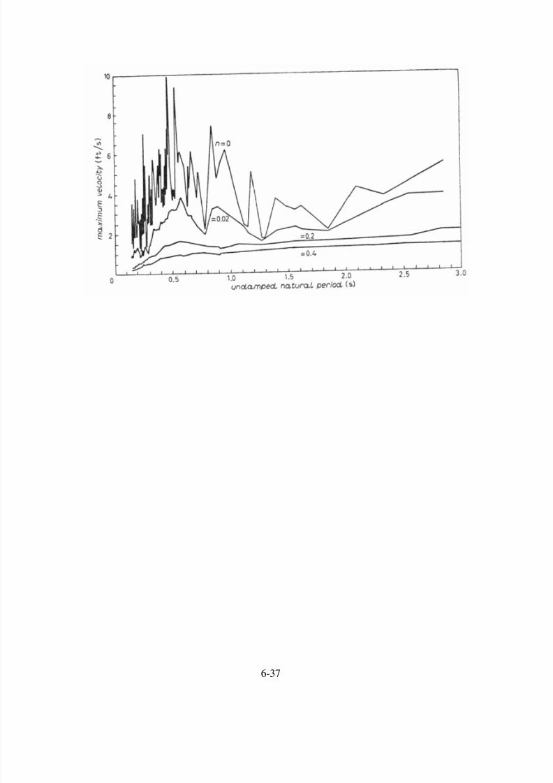
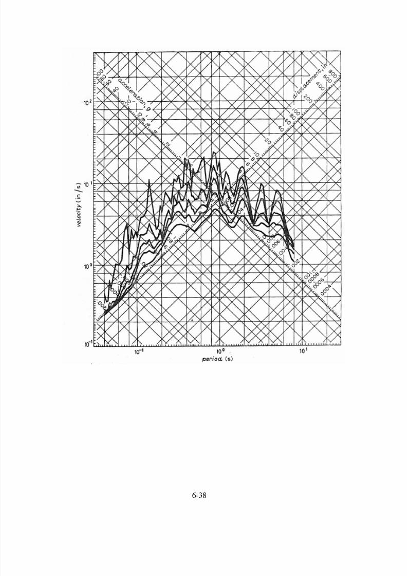
Spectral Methods
The problem of oscillations of a complex system of coupled linear oscillators can be quitecomplex to solve. However, it can be shown that for a linear system with n degrees of
freedom that is oscillating about its static equilibrium, then the motion can be represented
as the sum of n modes. In general, each mode has a particular frequency and mode shapeassociated with it. By summing the modes with the proper phase and amplitude, anypossible motion of the system can be produced. Buildings are continuous systems, and
therefore it would require an infinite set of modes to represent all the motions. However,
a reasonable approximation can be achieved by representing the building with a numberof discrete elements (e.g., the different floor slabs) that are coupled by spring elements
(e.g., moment resisting connections).
6-36
8/6/2019 Ch6 Buildings
http://slidepdf.com/reader/full/ch6-buildings 37/49
6-37
8/6/2019 Ch6 Buildings
http://slidepdf.com/reader/full/ch6-buildings 38/49
6-38

8/6/2019 Ch6 Buildings
http://slidepdf.com/reader/full/ch6-buildings 39/49
6-39

8/6/2019 Ch6 Buildings
http://slidepdf.com/reader/full/ch6-buildings 40/49
6-40
8/6/2019 Ch6 Buildings
http://slidepdf.com/reader/full/ch6-buildings 41/49
6-41

8/6/2019 Ch6 Buildings
http://slidepdf.com/reader/full/ch6-buildings 42/49
6-42

8/6/2019 Ch6 Buildings
http://slidepdf.com/reader/full/ch6-buildings 43/49
6-43
8/6/2019 Ch6 Buildings
http://slidepdf.com/reader/full/ch6-buildings 44/49
6-44

8/6/2019 Ch6 Buildings
http://slidepdf.com/reader/full/ch6-buildings 45/49
6-45

8/6/2019 Ch6 Buildings
http://slidepdf.com/reader/full/ch6-buildings 46/49
6-46
8/6/2019 Ch6 Buildings
http://slidepdf.com/reader/full/ch6-buildings 47/49
6-47

8/6/2019 Ch6 Buildings
http://slidepdf.com/reader/full/ch6-buildings 48/49
6-48

8/6/2019 Ch6 Buildings
http://slidepdf.com/reader/full/ch6-buildings 49/49
Homework Chapter 6
1. Assume that the base of a shear-beam (neglect bending deformations) with rigidity µ
and density ρ is subject to tangential displacement that given by ( ) xu t . Assume that the
top of the shear beam is a free surface.
( )0, 0
, 0 x
t u t
t t
<⎧ ⎫= ⎨ ⎬
>⎩ ⎭
a) Write the motion of the free end of the beam as a function of time.
b) Write the shear stress at the forced end of the beam as a function of time.c) How would this problem change if you were to allow bending deformations in the
beam?