
Ch5: ER Diagrams - Part 1 Much of the material presented in these slides was developed by Dr. Ramon...
34
Ch5: ER Diagrams - Part 1 Much of the material presented in these slides was developed by Dr. Ramon Lawrence at the University of Iowa
-
Upload
thomas-riley -
Category
Documents
-
view
213 -
download
0
Transcript of Ch5: ER Diagrams - Part 1 Much of the material presented in these slides was developed by Dr. Ramon...

Ch5: ER Diagrams - Part 1
Much of the material presented in these slides was developed by Dr. Ramon Lawrence at the University of Iowa

Topics
Notation basics (Some) Diagram rules Alternative notations

The Importance of Database Design Just as proper design is critical for developing large
applications, success of database projects is determined by the effectiveness of database design.
Some statistics on software projects (from Connolly textbook): 80 - 90% do not meet their performance goals 80% delivered late and over budget 40% fail or abandoned 10-20% meet all their criteria for success
The primary reasons for failure are improper requirements specifications, development methodologies, and design techniques.

Database Design Stages

Database Design
Requirements gathering and specifications provide you with a high-level understanding of the organization, its data, and the processes that you must model in the database.
Database design involves constructing a suitable model of this information.
Since the design process is complicated, especially for large databases, database design is divided into three phases: Conceptual database design Logical database design Physical database design

Conceptual Database Design Conceptual database design involves modeling the collected
information at a high-level of abstraction without using a particular data model or DBMS.
Since conceptual database design occurs independently from a particular DBMS or data model, we need high-level modeling languages to perform conceptual design.
Conceptual database design is top-down design as you start by specifying entities (real-world objects) then build up the model by defining new entities, attributes, and relationships. We will also see a bottom-up design technique called normalization where
you define the attributes first and then use dependency information to group them into relations.
The most popular database design language is the entity-relationship model proposed by Peter Chen in 1976. It is still in use today, but the ER model constructs are being merged with the modeling constructs of Unified Modeling Language (UML).

Example Relation Instances

ER Model Example (historical notation)

Crow’s Foot Notation
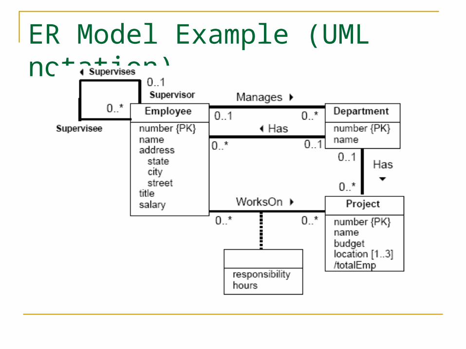
ER Model Example (UML notation)

Entity Types
An entity type is a group of objects with the same properties which are identified as having an independent existence. An entity type is the basic concept of the ER model and
represents a group of real-world objects that have properties. Note that an entity type does not always have to be a physical real-
world object such as a person or department, it can be an abstract concept such as a project or job.
An entity instance is a particular example or occurrence of an entity type. For example, an entity type is Employee. A entity instance is
'E1 - John Doe'. An entity set is a set of entity instances.

Representing Entity Types
In ER notation (and UML), entity types are represented by rectangles with the name of the entity type in the rectangle.
Examples:
An entity type name is normally a singular noun. That is, use Person instead of People, Project instead of Projects,
etc. The first letter of each word in the entity name is typically
capitalized. Note that colors are irrelevant when representing entity types (and
all other constructs) and are only used for aesthetics.

Relationship Types
A relationship type is a set of meaningful associations among entity types. Each relationship type is given a name that describes its function.
A relationship instance is a particular occurrence of a relationship type that relates entity instances. For example, WorksOn is a relationship type. A relationship
instance is that 'E1' works on project 'P1' or (E1,P1). A relationship set is a set of relationship instances. Note that there can be more than one relationship
between two entity types.

Visualizing Relationships
Note: This is an example of a many-to-many relationship. A project can have more than one employee, and an employee can work on more than one project.

Representing Relationship TypesIn classical ER notation, a simple relationship type between
two entities is represented as a named diamond that connects the two entity types.
In UML:
In Crow’s Foot Notation:

Relationship Degree
The degree of a relationship type is the number of entity types participating in the relationship. For example, WorksOn is a relationship type of degree two
as the two participating entity types are Employee and Project.
Relationships of degree two are binary, of degree three are ternary, and of degree four are quaternary. Relationships of arbitrary degree N are called n-ary.
Both ER and UML notation uses a diamond to represent relationships of degree higher than two.

Ternary Relationship Type Example
A project may require a part from multiple different suppliers.
• Crow's Foot does not support M-way (i.e., n-degree) relationships

Recursive Relationships A recursive relationship is a relationship
type where the same entity type participates more than once in different roles. For example, an employee has a supervisor. The
supervisor is also an employee. Crow’s foot notation:

Attributes
An attribute is a property of an entity or a relationship type. For example, entity type Employee has attributes name,
salary, title, etc. Some rules:
By convention, attribute names begin with a lower case letter.
Each attribute has a domain which is the set of allowable values for the attribute.
Different attributes may share the same domain, but a single attribute may have only one domain.

Simple and Complex Attributes An attribute is a simple attribute if it contains a
single component with an independent existence. For example, salary is a simple attribute. Simple attributes are often called atomic attributes.
An attribute is a composite attribute if it consists of multiple components each with an independent existence. For example, address is a complex attribute because it
consists of street, city, and state components (subattributes).
Question: Is the name attribute of Employee simple or complex?

Single- and Multi-Valued Attributes An attribute is a single-valued attribute if it consists of a single
value for each entity instance. For example, salary is a single-valued attribute.
An attribute is a multi-valued attribute if it may have multiple values for a single entity instance.
For example, a telephone number attribute for a person may be multivalued as people may have different phone numbers (home phone number, cell phone number, etc.)
A derived attribute is an attribute whose value is calculated from other attributes but is not physically stored. The calculation may involve attributes within the entity type of the
derived attribute and attributes in other entity types.

Keys
A candidate key is a minimal set of attributes that uniquely identifies each instance of an entity type. For example, the number attribute uniquely identifies an
Employee and is a candidate key for the Employee entity type. A primary key is a candidate key that is selected to identify each
instance of an entity type. The primary key is chosen from a set of candidate keys. For
instance, an employee may also have SSN as an attribute. The primary key may be either SSN or number as both are candidate keys.
A composite key is a key that consists of two or more attributes. For example, a course is uniquely identified only by the
department code (22C) and the course number within the department (144).

Attributes on Relationships
An attribute may be associated with a relationship type.
For example, the WorksOn relationship type has two attributes: responsibility and hours.
Note that these two attributes belong to the relationship and cannot belong to either of the two entities individually (as they would not exist without the relationship).

Attributes in the ER Model Example

Crow’s Foot Notation
Multi-valuedattribute
Primary key
Derivedattribute
Relationshipattributes
Compositeattribute
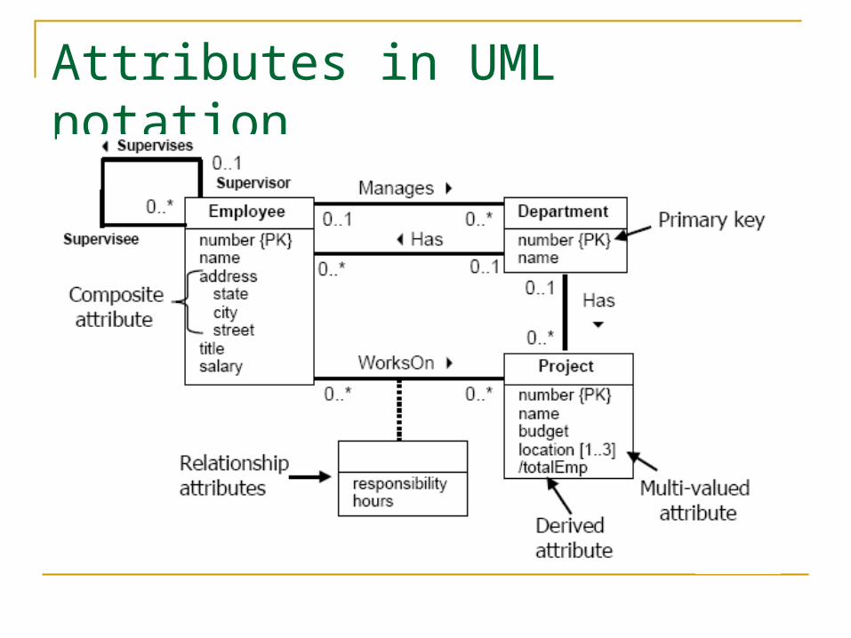
Attributes in UML notation

Relationship Cardinalities
Relationship cardinalities or multiplicities are used to restrict how entity types participate in relationships in order to model real-world constraints.
The multiplicity is the number of possible occurrences of an entity type that may relate to a single occurrence of an associated entity type through a particular relationship.
For binary relationships, there are three common types: one-to-one (1:1) one-to-many (1:* or 1:N) many-to-many (*:* or N:M)
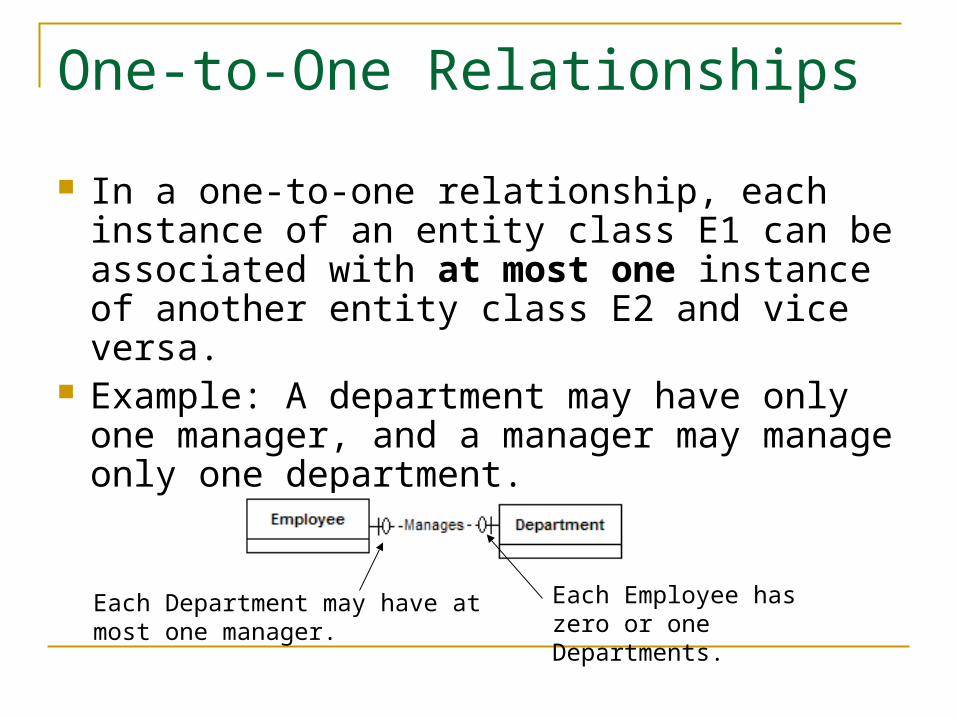
One-to-One Relationships
In a one-to-one relationship, each instance of an entity class E1 can be associated with at most one instance of another entity class E2 and vice versa.
Example: A department may have only one manager, and a manager may manage only one department.
Each Employee has zero or one Departments.
Each Department may have at most one manager.

One-to-One Relationship Example
Relationship explanation: A department may have only one manager. A manager(employee) may manage only one department.
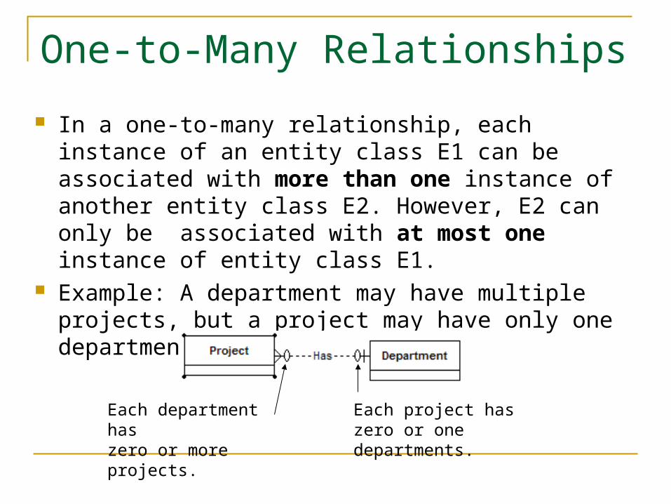
One-to-Many Relationships
In a one-to-many relationship, each instance of an entity class E1 can be associated with more than one instance of another entity class E2. However, E2 can only be associated with at most one instance of entity class E1.
Example: A department may have multiple projects, but a project may have only one department.
Each project haszero or one departments.
Each department haszero or more projects.

One-to-Many Relationship Example
Relationship explanation: A project may be associated with at most one department. A department may have multiple projects.

Many-to-Many Relationships
In a many-to-many relationship, each instance of an entity class E1 can be associated with more than one instance of another entity class E2 and vice versa.
Example: An employee may work on multiple projects, and a project may have multiple employees working on it.
Each project haszero or more employees.
Each employee works onzero or more projects.
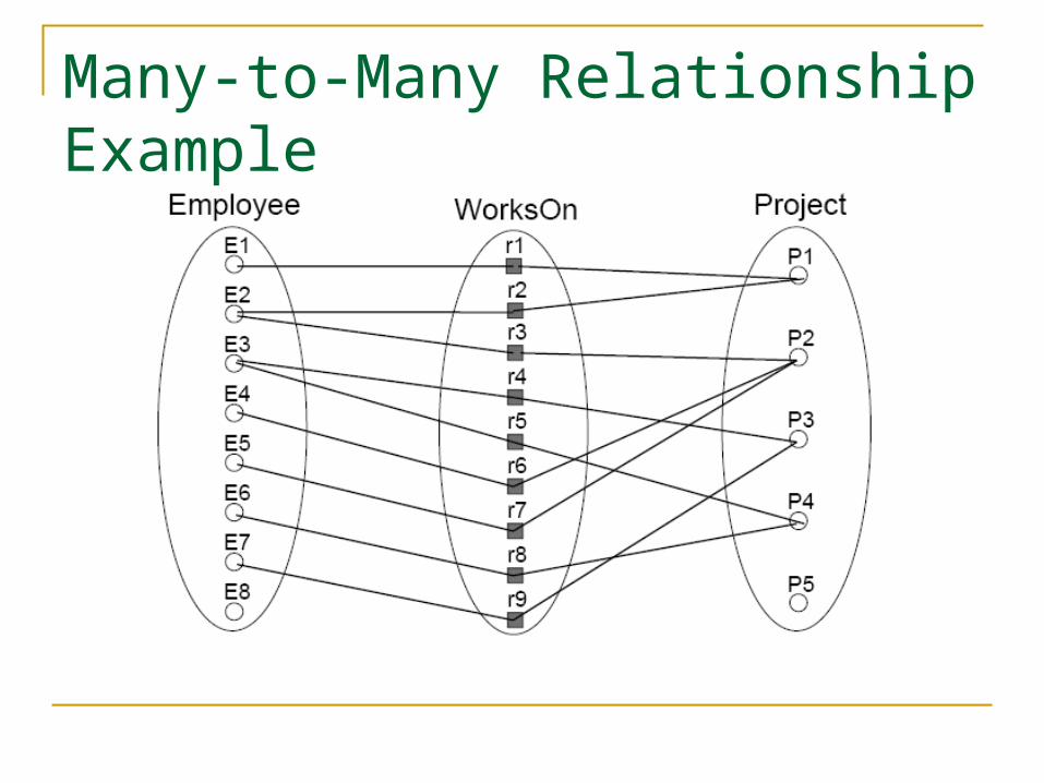
Many-to-Many Relationship Example

ER Design Question Construct a university database where:
Each student has an id, name, sex, birth date, and GPA. Each professor has a name and is in a department. Each department offers courses and has professors. A
department has a name and a building location. Each course has a name and number and may have
multiple sections. Each section is taught by a professor and has a section
number. Students enroll in sections of courses. They may only enroll
in a course once (and in a single section). Once a student completes a course, they receive a grade.