
Ch3 07 optical fibers.ppt - Sharif University of...
40
Chapter 3: Optical Devices Optical Fibers Optical Communications: Circuits, Systems and Devices Sep 2012 Sharif University of Technology 1 lecturer: Dr. Ali Fotowat Ahmady
Transcript of Ch3 07 optical fibers.ppt - Sharif University of...

Chapter 3: Optical Devices
Optical Fibers
Optical Communications: Circuits, Systems and Devices
Sep 2012 Sharif University of Technology 1
lecturer: Dr. Ali Fotowat Ahmady
Brief History of Optical Fiber Technology (1 of 2)
• Mid-1960s: Attenuation in bulk glass was 500dB/km- Attempted guiding structures included surface-wave devices
◦ Metallic tubes and hollow dielectric tubes- Kao and Hockham pointed out what had to be done to reduce attenuation
Chapter 3 Optical Devices Optical Fibers
Sep 2012 Sharif University of Technology 2
attenuation◦ Reduce concentration of transition-metal ions (Fe, Cu, Cr, Ni, Mn, Co) to less than 1 part per billion◦ Increase purity of SiO2 to make attenuation mostly scattering loss
- In 1971 Kapron et al. at Corning made a fiber with α ≈ 20dB/km◦ Used outside chemical vapor deposition
- By 1977, experimental fibers had α < 0.5 dB/km at λ = 1.2 μm

Brief History of Optical Fiber Technology (2 of 2)
• Dispersion produces pulse broadening and limits bit rate- Unclad fiber was widely used for imaging and short-distance transmission
◦ Very rapid pulse broadening → not suitable for communications
Chapter 3 Optical Devices Optical Fibers
Sep 2012 Sharif University of Technology 3
communications- Core-cladding fibers were named “weakly guiding fibers” in 1971 (Gloge)
◦ Essential for achieving low dispersion

Optical Fiber Types for Communications (1 of 3)
• Unclad fiber- Not used for communications because of very rapid pulse spreading due to high intermodal dispersion
• Multimode clad fiber (used in LANs and for short-haul applications)
Chapter 3 Optical Devices Optical Fibers
Sep 2012 Sharif University of Technology 4
• Multimode clad fiber (used in LANs and for short-haul applications)- Core refractive index > cladding refractive index- Usually the core refractive-index profile is graded quadratically to reduce pulse spreading due to intermodal dispersion- The most widely installed type has a core diameter of 62.5 μm and a cladding diameter of 125 μm

Optical Fiber Types for Communications (2 of 3)
• Single-mode clad fiber (used for long-haul applications)- Step-index: Core refractive index is a constant- Profiled index: Core refractive index is designed to achieve favorable group-velocity-dispersion characteristics- Core diameter 10 μm
Chapter 3 Optical Devices Optical Fibers
Sep 2012 Sharif University of Technology 5
- Core diameter 10 μm
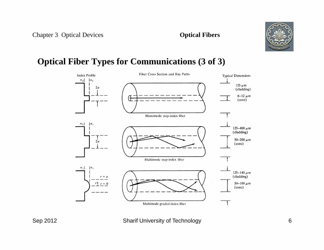
Optical Fiber Types for Communications (3 of 3)
Chapter 3 Optical Devices Optical Fibers
Sep 2012 Sharif University of Technology 6

Optical Fiber Waveguide Modes (1 of 2)
• Analysis involves Bessel functions and a lot of vector calculus- In a step-index fiber there are only two media, the core (refractive index n1) and the cladding (refractive index n2)- The mode that has a cutoff frequency equal to 0 is a hybrid electricmode (HE11), in which both Ez and Hz are non-zero
There are two polarizations with the same frequency and
Chapter 3 Optical Devices Optical Fibers
Sep 2012 Sharif University of Technology 7
11 z z◦ There are two polarizations with the same frequency and propagation constant (degenerate HE11 modes with different polarizations)◦ For 0 < V < 2.405 the HE11 mode is the only mode that can propagate (all others are below the cutoff frequency)◦ This is called “single-mode” operation, despite the fact that there are two degenerate modes

Optical Fiber Waveguide Modes (2 of 2)
• Assume a is the core radius, then the normalized frequency and normalized propagation constant are
Chapter 3 Optical Devices Optical Fibers
2 20 1 2V k a n n= −
2 21n nb β= − −
Sep 2012 Sharif University of Technology 8
2 2
1 0 1 1
1n nbn k n nβ= − −

Overview of Optical Fiber Manufacturing
• An optical fiber is drawn from a preform- Dimensions are 1 meter in length by 2 cm in diameter- Refractive-index profile is the same (relative to the outside diameter) as in the finished fiber
◦ The core is doped with GeO2 or P2O5 to increase the
Chapter 3 Optical Devices Optical Fibers
Sep 2012 Sharif University of Technology 9
The core is doped with GeO2 or P2O5 to increase the refractive index◦ B2O3 and F can be used in the cladding to decrease the refractive index
• Methods for preparing the preform all use some form of vapor deposition- It is very difficult to purify silica adequately in a bulk melt- In the vapor-deposition methods, SiO2 is obtained by reacting SiCl4 with O2 to produce a porous “soot” of silica
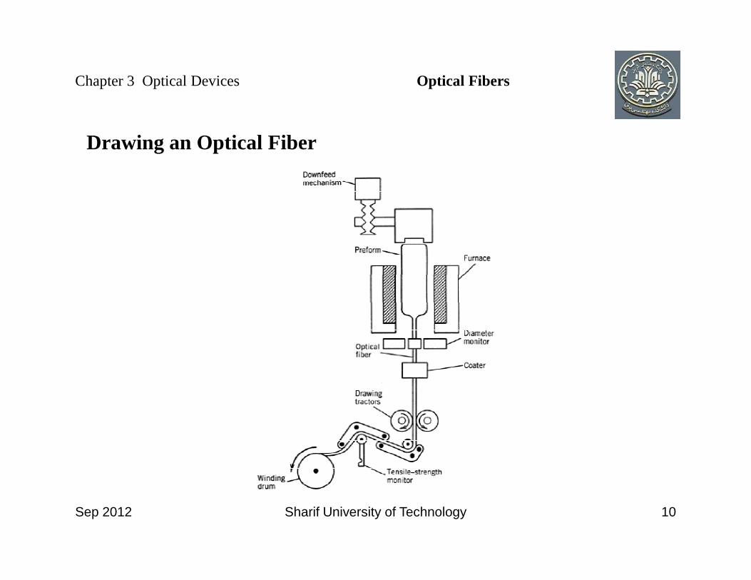
Drawing an Optical Fiber
Chapter 3 Optical Devices Optical Fibers
Sep 2012 Sharif University of Technology 10

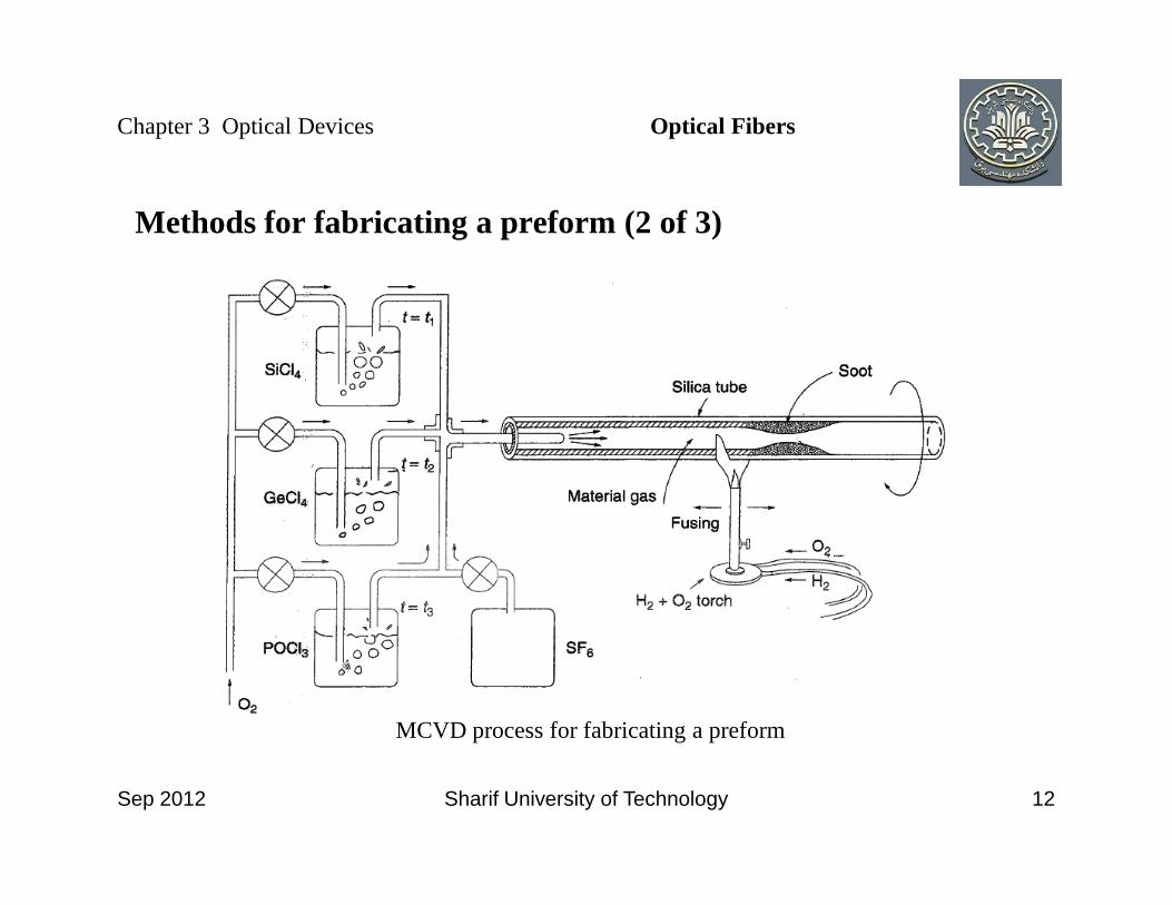
Methods for fabricating a preform (1 of 3)
• Modified chemical vapor deposition (MCVD)- The cladding and core are deposited on the inside of a fused silica tube- The refractive-index profile is controlled by adding various dopants as deposition progresses
Chapter 3 Optical Devices Optical Fibers
Sep 2012 Sharif University of Technology 11
dopants as deposition progresses- At the end, the tube is heated and collapses into a solid rod
• Outside vapor depostion (OVD)- The layers of the preform are deposited on the outside of a rotating mandrel using flame hydrolysis- The mandrel’s thermal expansion coefficient is larger than that of the preform, so the mandrel drops out after cooling- This process produces a central dip in the refractive index
Methods for fabricating a preform (2 of 3)
Chapter 3 Optical Devices Optical Fibers
Sep 2012 Sharif University of Technology 12
MCVD process for fabricating a preform

Methods for fabricating a preform (3 of 3)
• Vapor axial deposition (VAD)- Deposition occurs on the end of a rotating rod
Chapter 3 Optical Devices Optical Fibers
Sep 2012 Sharif University of Technology 13

Coating and Cabling
• Coating- Deposited immediately after the fiber is pulled- Purpose: Protection from abrasion- Surface flaws cause cracks to form
◦ Protection from H2O
Chapter 3 Optical Devices Optical Fibers
Sep 2012 Sharif University of Technology 14
Protection from H2O- Exposure to H2O would promote growth of crystallites → fracture
• Cable- Jacket contains one to many fiber bundles, each inside a buffer tube- Purposes:
◦ Mechanical strength◦ Protection from H2O and other environmental chemicals◦ Prevention of micro bending losses

Properties of Fibers for Communications (1 of 2)
• Numerical aperture- Useful only for multimode fibers and incoherent sources (e.g. LEDs)
• Attenuation- Imperfect light coupling into the fiber- Absorption
Chapter 3 Optical Devices Optical Fibers
Sep 2012 Sharif University of Technology 15
- Absorption- Scattering
• Dispersion- Modal Dispersion: different modes propagate at different group velocities; Meaningful only for multimode fibers- Chromatic Dispersion
•Group-velocity dispersion- Important only for single-mode fibers
Properties of Fibers for Communications (2 of 2)
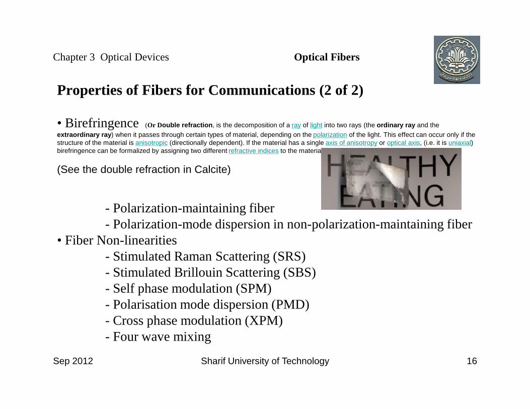
• Birefringence (Or Double refraction, is the decomposition of a ray of light into two rays (the ordinary ray and the extraordinary ray) when it passes through certain types of material, depending on the polarization of the light. This effect can occur only if the structure of the material is anisotropic (directionally dependent). If the material has a single axis of anisotropy or optical axis, (i.e. it is uniaxial) birefringence can be formalized by assigning two different refractive indices to the material for different polarizations.
(See the double refraction in Calcite)
- Polarization-maintaining fiber
Chapter 3 Optical Devices Optical Fibers
Sep 2012 Sharif University of Technology 16
- Polarization-maintaining fiber- Polarization-mode dispersion in non-polarization-maintaining fiber
• Fiber Non-linearities- Stimulated Raman Scattering (SRS)- Stimulated Brillouin Scattering (SBS)- Self phase modulation (SPM)- Polarisation mode dispersion (PMD)- Cross phase modulation (XPM)- Four wave mixing

Numerical Aperture (1 of 2)
• It is defined as
where θm is the system’s maximum acceptance half-angle and n is the refractive index of the outside material
Chapter 3 Optical Devices Optical Fibers
2 2 1 21 2 1
1
sin( ) 2 ,mn nNA n n n
nθ
−= = − ≅ ∆ ∆ =
Sep 2012 Sharif University of Technology 17
index of the outside material

Numerical Aperture (2 of 2)
• If n = 1, then 0 ≤ NA ≤ 1- 0 means that no light gets into the system- 1 means that all of the light propagating towards the system gets in- Power into system (NA)2
• Typically, NA= 0.15 for single mode fiber and 0.3 for MMF
Chapter 3 Optical Devices Optical Fibers
Sep 2012 Sharif University of Technology 18
• Typically, NA= 0.15 for single mode fiber and 0.3 for MMF

Attenuation (1 of 3)
• Basic formula:
- α is the attenuation coefficient (units are cm−1 or m−1)- Loss in dB = 10(log10 e)αL ≈ 4.343 αL
Chapter 3 Optical Devices Optical Fibers
LPower received at a distance L from the transmitter ePower transmitted
α=
Sep 2012 Sharif University of Technology 19
- Loss in dB = 10(log10 e)αL ≈ 4.343 αL- Practical units of the attenuation coefficient are dB/km or dB/m
• Origins of attenuation in silica fibers in the 1.2 - 1.6 μm region- Absorption
◦ Mostly due to residual water in silica fiber◦ 1st overtone of stretching mode of H2O is at 1.4 μm, 2nd at 0.945 μm◦ Because H may occur at the end of a O-Si-O chain, an H-O vibration can be coupled to an Si-O vibration (as at 1.24 μm)

Attenuation (2 of 3)
- Rayleigh scattering (same basic mechanism as makes the sky blue)◦ caused by small variations in the density of glass as it cools ◦ Causes a change in direction which usually causes light to escape from the core
Chapter 3 Optical Devices Optical Fibers
Sep 2012 Sharif University of Technology 20
escape from the core◦ Attenuation coefficient: αR = Cλ−4 where C ≈ 0.7−0.9
(dB/km)(μm)−4
◦ Important for λ < 1.2μm

Attenuation (3 of 3)
• Attenuation of light in silica fiber in the near-infrared region: ν1: O–Si–O bending mode, ν3
1: O–H stretching mode
Chapter 3 Optical Devices Optical Fibers
Sep 2012 Sharif University of Technology 21

Bending Loss (1 of 2)
Chapter 3 Optical Devices Optical Fibers
Sep 2012 Sharif University of Technology 22
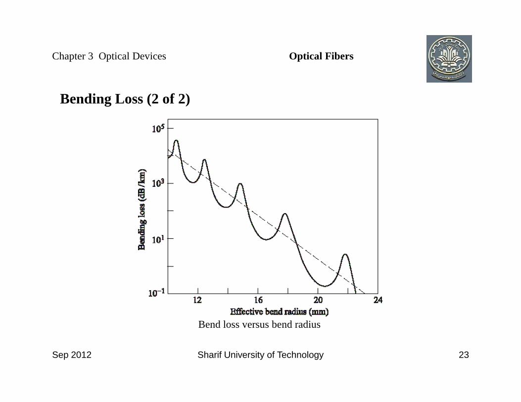
Bending Loss (2 of 2)
Chapter 3 Optical Devices Optical Fibers
Sep 2012 Sharif University of Technology 23
Bend loss versus bend radius

Dispersion (1 of 2)
• Dispersion is the property that the velocity of light depends on the optical frequency or the mode of propagation in a waveguide• Dispersion causes the duration and shape of an optical pulse to change in the course of propagation, causing bit errors in reception• Causes of dispersion:
Chapter 3 Optical Devices Optical Fibers
Sep 2012 Sharif University of Technology 24
• Causes of dispersion:- Material dispersion: Frequency dependence of the refractive index- Waveguide dispersion: Frequency dependence of the propagation constant in a fiber mode- Intermodal dispersion: Different fiber modes have different propagation constants at the same frequency, making pulses launched simultaneously in different modes arrive at the receiver at different times

Dispersion (2 of 2)
- Group-velocity dispersion: A single pulse in a single fiber mode contains a range of frequencies, each of which propagates at a different velocity
Chapter 3 Optical Devices Optical Fibers
Sep 2012 Sharif University of Technology 25

Intermodal dispersion in multimode fibers (1 of 5)
• Different modes of propagation in a waveguide correspond to different E and H field patterns
- For a fiber with a sufficiently small core radius, there is only one propagating mode
• Different modes propagate at different speeds because some modes take a
Chapter 3 Optical Devices Optical Fibers
Sep 2012 Sharif University of Technology 26
• Different modes propagate at different speeds because some modes take a longer path through a fiber than others• Also called multipath dispersion• The differential mode delay for step-index fiber
is the difference in arrival times of two pulses launched into different modes- vc ≈ c/ncore is the propagation velocity of a monochromatic wave in the core of the fiber
(Units: μs, ns or ps)1 2c cL v L v−

Intermodal dispersion in multimode fibers (2 of 5)
• Differential mode delay is important for LAN technologies• where θc = critical angle and • For a fiber of length L, the difference in arrival times of a pulse that travels along an axial ray and one that travels along a meridional ray at the critical angle is
Chapter 3 Optical Devices Optical Fibers
sin cl s θ= sin c clad coren nθ =
Sep 2012 Sharif University of Technology 27
angle is 11
sincore
c
core core
clad
n Lt
c
n L nc n
θ
∆ = −
= ∆
where core clad
core
n nn
−∆ =

Intermodal dispersion in multimode fibers (3 of 5)
• Numerical value for clad, weakly guiding fiber (ncore ≈ nclad ≈ 1.5 andΔ ≈ 3 × 10⁻³)
• Requirement for minimal inter symbol interference:where B = bit rate
Chapter 3 Optical Devices Optical Fibers
15 /t L ns km∆ ≈
1B t∆ <
Sep 2012 Sharif University of Technology 28
where B = bit rate• Maximum length bit-rate product for weakly guiding step-index fiber:
• Numerical values for weakly guiding fiber, for which ncore ≈ nclad ≈ 1.5:- Step-index multimode (Δ ≈ 3×10⁻³): BL < 67 Mb-km/s (MHz-km)
1B t∆ <
2clad
core
n cBLn
<∆

Intermodal dispersion in multimode fibers (4 of 5)
• Unclad multimode (Δ ≈ 0.33): BL < 0.4 Mb-km/s (MHz-km)- Because 90◦ − θc,unclad >> 90◦ − θc,clad the path difference per km of fiber between an axial ray and a ray that bounces back and forth at the critical angle is much greater for unclad fiber than for clad, weakly guiding fiber
• Graded-index multimode fiber can have higher values of BL than step-index
Chapter 3 Optical Devices Optical Fibers
Sep 2012 Sharif University of Technology 29
• Graded-index multimode fiber can have higher values of BL than step-index multimode fiber
- The α-profile used to model graded-index fiber is
where a = core radius and
( )1
2
1 ,( )
,
n a if an
n if a
αρ ρρ
ρ
− ∆ ≤ = >
( )1 2 1n n n∆ = −

Intermodal dispersion in multimode fibers (5 of 5)
- The value α = 2 produces zero intermodal dispersion in the paraxial approximation of geometrical optics
◦ The actual bit-rate limit that can be achieved with α = 2 is
Chapter 3 Optical Devices Optical Fibers
21
8cBLn
<∆
Sep 2012 Sharif University of Technology 30
◦ The graded-index core acts like a distributed lens, approximately equalizing the optical path lengths traveled by different rays
1

Group Velocity Dispersion (1 of 2)
• Group-velocity dispersion in a single fiber mode- The phase velocity of a wave, vp = ω/β, is the velocity at which a monochromatic wave travels- The group velocity, vg = dω/dβ, is the velocity of a pulse
◦ A pulse is a superposition of many frequencies, by Fourier analysis
Chapter 3 Optical Devices Optical Fibers
Sep 2012 Sharif University of Technology 31
Fourier analysis◦ If ω is not a linear function of β, then vg ≠ vp
- The differential group delay, d(L/vg), is the difference in arrival times of two pulses centered at different wavelengths
◦ Chromatic dispersion:
( )1 gd vD
dλ= (units: ps per nm-km)

Group Velocity Dispersion (2 of 2)
◦ The high-wavelength and low-wavelength parts of a single pulse
per unit distance, per unit wavelength difference
Chapter 3 Optical Devices Optical Fibers
( )1L
gd L vDGD
dλ=
Sep 2012 Sharif University of Technology 32
per unit distance, per unit wavelength difference

Group Velocity Dispersion in Single Mode Fiber (1 of 4)
• Difference in arrival times of waves at wavelengths λ and λ+Δλ:
Chapter 3 Optical Devices Optical Fibers
1
g
dt Ld v
LD
λλ
λ
∆ = ∆
= ∆
Sep 2012 Sharif University of Technology 33
- Material dispersion:
- Waveguide dispersion:
M WD D D= +2 2
2
1 2g gM
dn dnD
c d dπ
λ ωλ= = −
( ) ( )2 22 2
2 22
2 g gW
n dnd Vb d VbD V
n d dVdVπ
ω ωλ
∆= − − +

Group Velocity Dispersion in Single Mode Fiber (2 of 4)
• Requirement for minimal inter symbol interference:
Chapter 3 Optical Devices Optical Fibers
1 1B t BL D λ∆ < ⇒ ∆ <
Sep 2012 Sharif University of Technology 34

Nonlinear Optics
• Comprises some of the most striking effects in physics- Light of a single color enters a transparent substance- Different colors emerge on the other side
• Examples:- Second harmonic generation: ω in, 2ω out- Stimulated Raman scattering: ω in, ω = ω − ω out
Chapter 3 Optical Devices Optical Fibers
Sep 2012 Sharif University of Technology 35
- Stimulated Raman scattering: ωL in, ωS = ωL − ωv out- Stimulated Brillouin scattering: ωL in, ωB = ωL − ωa out

Nonlinear Optical Effects in Fibers (1 of 2)
• When an optical electric field is stronger than about 10−5 to 10−6 of a typical electric field inside an atom ( 1011 V/m), there are small but measurable departures of the linear relation between electric field and induced dipole moment per unit volume, even in “ordinary” materials such as silica glass
Chapter 3 Optical Devices Optical Fibers
Sep 2012 Sharif University of Technology 36
• Single-mode fibers in long-haul telecommunication systems have all the right conditions for producing nonlinear optical effects
- High power/unit area in the core → high optical electric field- Long propagation distance at high power/unit area

Nonlinear Optical Effects in Fibers (2 of 2)
• Important nonlinear effects for optical communications include:- Changes in the refractive index which are proportional to optical power
◦ Self-phase modulation broadens the signal spectrum◦ Dispersion then increases the pulse duration and bit error rate
Chapter 3 Optical Devices Optical Fibers
Sep 2012 Sharif University of Technology 37
rate- Four-wave mixing: The optical analog of intermodulation distortion- Optical gain, pumped by optical power
Questions
Chapter 3 Optical Devices Optical Fibers
Sep 2012 Sharif University of Technology 38

Group Velocity Dispersion in Single Mode Fiber (3 of 4)
• Wavelength spread Δλ for a pulse
- The Fourier integral theorem (applied to a Gaussian waveform) says that: |Δν| ·|Δt| ≈ 1,
Chapter 3 Optical Devices Optical Fibers
2v vv v
λ λλ
λ∆ ∆
= ⇒ ∆ = ∆
Sep 2012 Sharif University of Technology 39
says that: |Δν| ·|Δt| ≈ 1,Then, for a bandwidth-limited pulse, |Δν| ≈ B- For a non-bandwidth-limited pulse,
• Requirement for minimal inter symbol interference:
2
v B Bv
λλ∆ > ⇒ ∆ >
22 2
1 v vBL B LD B D Dλ λ λ
< < ⇒ <∆

Group Velocity Dispersion in Single Mode Fiber (4 of 4)
• Which criterion should one use to determine the maximum bit rate B that an optical channel can carry,
- The first criterion (on BL) should be applied when the source is a
Chapter 3 Optical Devices Optical Fibers
22
1 vBL or B LD Dλ λ
< <∆ ?
Sep 2012 Sharif University of Technology 40
- The first criterion (on BL) should be applied when the source is a broadband laser or an LED. - The second criterion (on B2L) should be applied when the laser source is narrowband, and the signal is created by externally modulating the laser light (using on-off keying).
◦ The frequency width of a pulse may change as the pulse propagates, as a result of self-phase modulation


![The Meaning Of The Glorious Quran - maktabasalik.com · [2:1] ﻢﻟا Alif. Lam. Mim. Alif. Lam. Mim. Alif. Lam. Mim. [2:2] ﻦَﻴِﻘﱠﺘُﻤْﻠِﻟ ىًﺪُه ِﻪﻓﻴِ](https://static.fdocuments.in/doc/165x107/5e1cdbb5a9261a003a2a307f/the-meaning-of-the-glorious-quran-21-ii-alif-lam-mim-alif-lam-mim.jpg)
