Ch21 Metal Cutting Theory Wiley
44
©2002 John Wiley & Sons , Inc. M. P. Groov er, “Fundamentals of Modern Manufacturing 2/e” THEORY OF METAL MACHINING • Overview of Machining Technology • Theory of Chip Formation in Metal Machining • Force Relationships and the Merchant Equation • Power and Energy Relationsh ips in Machi ning • Cutting Temperature
Transcript of Ch21 Metal Cutting Theory Wiley
8/4/2019 Ch21 Metal Cutting Theory Wiley
http://slidepdf.com/reader/full/ch21-metal-cutting-theory-wiley 1/44
©2002 John Wiley & Sons, Inc. M. P. Groover, “Fundamentals of Modern Manufacturing 2/e”
THEORY OF METAL MACHINING
• Overview of Machining Technology
• Theory of Chip Formation in Metal Machining
• Force Relationships and the Merchant Equation
• Power and Energy Relationships in Machining
• Cutting Temperature
8/4/2019 Ch21 Metal Cutting Theory Wiley
http://slidepdf.com/reader/full/ch21-metal-cutting-theory-wiley 2/44
©2002 John Wiley & Sons, Inc. M. P. Groover, “Fundamentals of Modern Manufacturing 2/e”
Material Removal Processes
A family of shaping operations, the common feature ofwhich is removal of material from a starting workpartso the remaining part has the desired shape
• Categories: Machining – material removal by a sharp cutting
tool, e.g., turning, milling, drilling
Abrasive processes – material removal by hard,abrasive particles, e.g., grinding
Nontraditional processes - various energy formsother than sharp cutting tool to remove material

8/4/2019 Ch21 Metal Cutting Theory Wiley
http://slidepdf.com/reader/full/ch21-metal-cutting-theory-wiley 3/44
©2002 John Wiley & Sons, Inc. M. P. Groover, “Fundamentals of Modern Manufacturing 2/e”
Machining
Cutting action involves shear deformation of workmaterial to form a chip
• As chip is removed, a new surface is exposed
Figure 21.2 - (a) A cross-sectional view of the machining process, (b)tool with negative rake angle; compare with positive rake angle in (a)

8/4/2019 Ch21 Metal Cutting Theory Wiley
http://slidepdf.com/reader/full/ch21-metal-cutting-theory-wiley 4/44
©2002 John Wiley & Sons, Inc. M. P. Groover, “Fundamentals of Modern Manufacturing 2/e”
Why Machining is Important
• Variety of work materials can be machined
Most frequently applied to metals
• Variety of part shapes and special geometry
features possible, such as:
Screw threads
Accurate round holes
Very straight edges and surfaces
•Good dimensional accuracy and surface finish

8/4/2019 Ch21 Metal Cutting Theory Wiley
http://slidepdf.com/reader/full/ch21-metal-cutting-theory-wiley 5/44
©2002 John Wiley & Sons, Inc. M. P. Groover, “Fundamentals of Modern Manufacturing 2/e”
Disadvantages with Machining
• Wasteful of material
Chips generated in machining are wasted material,at least in the unit operation
• Time consuming A machining operation generally takes more time
to shape a given part than alternative shapingprocesses, such as casting, powder metallurgy, orforming

8/4/2019 Ch21 Metal Cutting Theory Wiley
http://slidepdf.com/reader/full/ch21-metal-cutting-theory-wiley 6/44
©2002 John Wiley & Sons, Inc. M. P. Groover, “Fundamentals of Modern Manufacturing 2/e”
Machining in the Manufacturing Sequence
• Generally performed after other manufacturingprocesses, such as casting, forging, and bar drawing
Other processes create the general shape of the
starting workpart Machining provides the final shape, dimensions,
finish, and special geometric details that otherprocesses cannot create

8/4/2019 Ch21 Metal Cutting Theory Wiley
http://slidepdf.com/reader/full/ch21-metal-cutting-theory-wiley 7/44
©2002 John Wiley & Sons, Inc. M. P. Groover, “Fundamentals of Modern Manufacturing 2/e”
Machining Operations
• Most important machining operations:
Turning
Drilling
Milling
• Other machining operations:
Shaping and planing
Broaching
Sawing

8/4/2019 Ch21 Metal Cutting Theory Wiley
http://slidepdf.com/reader/full/ch21-metal-cutting-theory-wiley 8/44
©2002 John Wiley & Sons, Inc. M. P. Groover, “Fundamentals of Modern Manufacturing 2/e”
Turning
Single point cutting tool removes material from arotating workpiece to form a cylindrical shape
Figure 21.3 (a) turning

8/4/2019 Ch21 Metal Cutting Theory Wiley
http://slidepdf.com/reader/full/ch21-metal-cutting-theory-wiley 9/44
©2002 John Wiley & Sons, Inc. M. P. Groover, “Fundamentals of Modern Manufacturing 2/e”
Drilling
Used to create a round hole, usually by means of arotating tool (drill bit) that has two cutting edges
Figure 21.3 - The three mostcommon types of machining
process: (b) drilling
8/4/2019 Ch21 Metal Cutting Theory Wiley
http://slidepdf.com/reader/full/ch21-metal-cutting-theory-wiley 10/44
©2002 John Wiley & Sons, Inc. M. P. Groover, “Fundamentals of Modern Manufacturing 2/e”
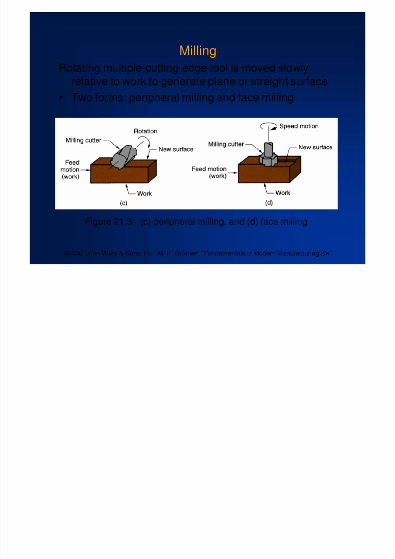
Milling
Rotating multiple-cutting-edge tool is moved slowlyrelative to work to generate plane or straight surface
• Two forms: peripheral milling and face milling
Figure 21.3 - (c) peripheral milling, and (d) face milling
8/4/2019 Ch21 Metal Cutting Theory Wiley
http://slidepdf.com/reader/full/ch21-metal-cutting-theory-wiley 11/44
©2002 John Wiley & Sons, Inc. M. P. Groover, “Fundamentals of Modern Manufacturing 2/e”
Cutting Tool Classification
1. Single-Point Tools
One cutting edge
Turning uses single point tools
Point is usually rounded to form a nose radius 2. Multiple Cutting Edge Tools
More than one cutting edge
Motion relative to work usually achieved byrotating
Drilling and milling use rotating multiple cuttingedge tools.

8/4/2019 Ch21 Metal Cutting Theory Wiley
http://slidepdf.com/reader/full/ch21-metal-cutting-theory-wiley 12/44
©2002 John Wiley & Sons, Inc. M. P. Groover, “Fundamentals of Modern Manufacturing 2/e”
Figure 21.4 - (a) A single-point tool showing rake face, flank, and toolpoint; and (b) a helical milling cutter, representative of tools with
multiple cutting edges

8/4/2019 Ch21 Metal Cutting Theory Wiley
http://slidepdf.com/reader/full/ch21-metal-cutting-theory-wiley 13/44
©2002 John Wiley & Sons, Inc. M. P. Groover, “Fundamentals of Modern Manufacturing 2/e”
Cutting Conditions in Machining
• The three dimensions of a machining process:
Cutting speed v – primary motion
Feed f – secondary motion
Depth of cut d –
penetration of tool below originalwork surface
• For certain operations, material removal rate can befound as
MRR = v f d
where v = cutting speed; f = feed; d = depth of cut

8/4/2019 Ch21 Metal Cutting Theory Wiley
http://slidepdf.com/reader/full/ch21-metal-cutting-theory-wiley 14/44
©2002 John Wiley & Sons, Inc. M. P. Groover, “Fundamentals of Modern Manufacturing 2/e”
Cutting Conditions for Turning
Figure 21.5-
Cutting speed, feed, and depth of cut for a turningoperation

8/4/2019 Ch21 Metal Cutting Theory Wiley
http://slidepdf.com/reader/full/ch21-metal-cutting-theory-wiley 15/44
©2002 John Wiley & Sons, Inc. M. P. Groover, “Fundamentals of Modern Manufacturing 2/e”
Roughing vs. Finishing in Machining
In production, several roughing cuts are usually takenon the part, followed by one or two finishing cuts
• Roughing - removes large amounts of material fromthe starting workpart
Creates shape close to desired geometry, butleaves some material for finish cutting
High feeds and depths, low speeds
• Finishing - completes part geometry
Achieves final dimensions, tolerances, and finish Low feeds and depths, high cutting speeds

8/4/2019 Ch21 Metal Cutting Theory Wiley
http://slidepdf.com/reader/full/ch21-metal-cutting-theory-wiley 16/44
©2002 John Wiley & Sons, Inc. M. P. Groover, “Fundamentals of Modern Manufacturing 2/e”
Machine Tools
A power-driven machine that performs a machiningoperation, including grinding
• Functions in machining:
Holds workpart Positions tool relative to work
Provides power at speed, feed, and depth thathave been set
•
The term is also applied to machines that performmetal forming operations
8/4/2019 Ch21 Metal Cutting Theory Wiley
http://slidepdf.com/reader/full/ch21-metal-cutting-theory-wiley 17/44
©2002 John Wiley & Sons, Inc. M. P. Groover, “Fundamentals of Modern Manufacturing 2/e”
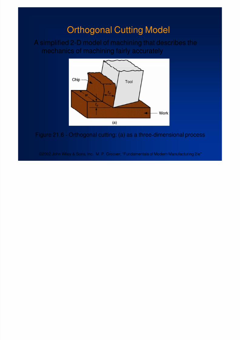
Orthogonal Cutting Model
A simplified 2-D model of machining that describes themechanics of machining fairly accurately
Figure 21.6 - Orthogonal cutting: (a) as a three-dimensional process

8/4/2019 Ch21 Metal Cutting Theory Wiley
http://slidepdf.com/reader/full/ch21-metal-cutting-theory-wiley 18/44
©2002 John Wiley & Sons, Inc. M. P. Groover, “Fundamentals of Modern Manufacturing 2/e”
Chip Thickness Ratio
where r = chip thickness ratio ; t o = thickness of thechip prior to chip formation; and t c = chip thicknessafter separation
• Chip thickness after cut is always greater than before,
so chip ratio is always less than 1.0
c
o
t
t r

8/4/2019 Ch21 Metal Cutting Theory Wiley
http://slidepdf.com/reader/full/ch21-metal-cutting-theory-wiley 19/44
©2002 John Wiley & Sons, Inc. M. P. Groover, “Fundamentals of Modern Manufacturing 2/e”
Determining Shear Plane Angle
• Based on the geometric parameters of the orthogonal
model, the shear plane angle can be determined as:
where r = chip ratio, and = rake angle
sin
costanr
r
1

8/4/2019 Ch21 Metal Cutting Theory Wiley
http://slidepdf.com/reader/full/ch21-metal-cutting-theory-wiley 20/44
©2002 John Wiley & Sons, Inc. M. P. Groover, “Fundamentals of Modern Manufacturing 2/e”
Figure 21.7 - Shear strain during chip formation: (a) chip formation
depicted as a series of parallel plates sliding relative to each other,(b) one of the plates isolated to show shear strain, and (c) shearstrain triangle used to derive strain equation

8/4/2019 Ch21 Metal Cutting Theory Wiley
http://slidepdf.com/reader/full/ch21-metal-cutting-theory-wiley 21/44
©2002 John Wiley & Sons, Inc. M. P. Groover, “Fundamentals of Modern Manufacturing 2/e”
Shear Strain
Shear strain in machining can be computed from thefollowing equation, based on the preceding parallelplate model:
= tan( - ) + cot
where = shear strain, = shear plane angle, and = rake angle of cutting tool

8/4/2019 Ch21 Metal Cutting Theory Wiley
http://slidepdf.com/reader/full/ch21-metal-cutting-theory-wiley 22/44
©2002 John Wiley & Sons, Inc. M. P. Groover, “Fundamentals of Modern Manufacturing 2/e”
Figure 21.8-
More realistic view of chip formation, showing shearzone rather than shear plane. Also shown is the secondary shear
zone resulting from tool-chip friction

8/4/2019 Ch21 Metal Cutting Theory Wiley
http://slidepdf.com/reader/full/ch21-metal-cutting-theory-wiley 23/44
©2002 John Wiley & Sons, Inc. M. P. Groover, “Fundamentals of Modern Manufacturing 2/e”
Four Basic Types of Chip in Machining
1. Discontinuous chip
2. Continuous chip
3. Continuous chip with Built-up Edge (BUE)
4. Serrated chip

8/4/2019 Ch21 Metal Cutting Theory Wiley
http://slidepdf.com/reader/full/ch21-metal-cutting-theory-wiley 24/44
©2002 John Wiley & Sons, Inc. M. P. Groover, “Fundamentals of Modern Manufacturing 2/e”
Segmented Chip•
Brittle work materials(e.g., cast irons)
• Low cutting speeds
• Large feed and depth ofcut
•High tool
-chip friction
Figure 21.9 - Four types of chipformation in metal cutting:
(a) segmented

8/4/2019 Ch21 Metal Cutting Theory Wiley
http://slidepdf.com/reader/full/ch21-metal-cutting-theory-wiley 25/44
©2002 John Wiley & Sons, Inc. M. P. Groover, “Fundamentals of Modern Manufacturing 2/e”
Continuous Chip
• Ductile work materials(e.g., low carbon steel)
• High cutting speeds
• Small feeds and depths
• Sharp cutting edge on
the tool
• Low tool-chip friction
Figure 21.9 - Four types of chipformation in metal cutting:
(b) continuous
8/4/2019 Ch21 Metal Cutting Theory Wiley
http://slidepdf.com/reader/full/ch21-metal-cutting-theory-wiley 26/44
©2002 John Wiley & Sons, Inc. M. P. Groover, “Fundamentals of Modern Manufacturing 2/e”
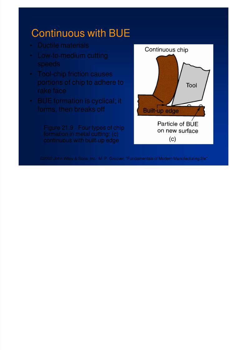
Continuous with BUE
• Ductile materials• Low-to-medium cutting
speeds
• Tool-chip friction causesportions of chip to adhere torake face
• BUE formation is cyclical; itforms, then breaks off
Figure 21.9-
Four types of chipformation in metal cutting: (c)continuous with built-up edge

8/4/2019 Ch21 Metal Cutting Theory Wiley
http://slidepdf.com/reader/full/ch21-metal-cutting-theory-wiley 27/44
©2002 John Wiley & Sons, Inc. M. P. Groover, “Fundamentals of Modern Manufacturing 2/e”
Serrated Chip• Semicontinuous - saw-
tooth appearance• Cyclical chip formation
of alternating high shearstrain then low shearstrain
•Most closely associatedwith difficult-to-machinemetals at high cuttingspeeds
Figure 21.9 - Four types of chipformation in metal cutting: (d)serrated
8/4/2019 Ch21 Metal Cutting Theory Wiley
http://slidepdf.com/reader/full/ch21-metal-cutting-theory-wiley 28/44
©2002 John Wiley & Sons, Inc. M. P. Groover, “Fundamentals of Modern Manufacturing 2/e”
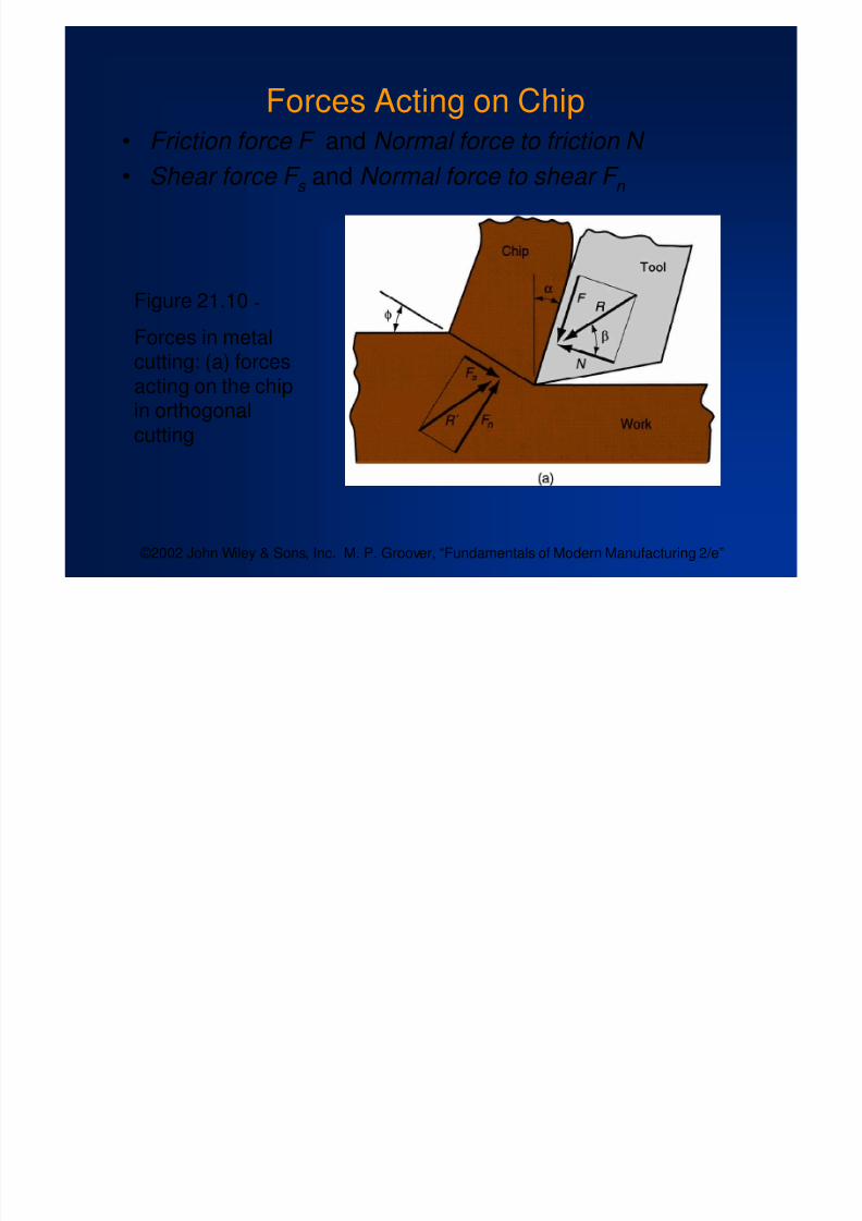
Forces Acting on Chip• Friction force F and Normal force to friction N
• Shear force F s and Normal force to shear F n
Figure 21.10-
Forces in metalcutting: (a) forcesacting on the chipin orthogonalcutting

8/4/2019 Ch21 Metal Cutting Theory Wiley
http://slidepdf.com/reader/full/ch21-metal-cutting-theory-wiley 29/44
©2002 John Wiley & Sons, Inc. M. P. Groover, “Fundamentals of Modern Manufacturing 2/e”
Resultant Forces
• Vector addition of F and N = resultant R
• Vector addition of F s and F n = resultant R '
• Forces acting on the chip must be in balance:
R ' must be equal in magnitude to R
R ’ must be opposite in direction to R
R ’ must be collinear with R

8/4/2019 Ch21 Metal Cutting Theory Wiley
http://slidepdf.com/reader/full/ch21-metal-cutting-theory-wiley 30/44
©2002 John Wiley & Sons, Inc. M. P. Groover, “Fundamentals of Modern Manufacturing 2/e”
Coefficient of Friction
Coefficient of friction between tool and chip:
Friction angle related to coefficient of friction asfollows:
N
F
tan

8/4/2019 Ch21 Metal Cutting Theory Wiley
http://slidepdf.com/reader/full/ch21-metal-cutting-theory-wiley 31/44
©2002 John Wiley & Sons, Inc. M. P. Groover, “Fundamentals of Modern Manufacturing 2/e”
Shear Stress
Shear stress acting along the shear plane:
sin
w t A o
s
where As = area of the shear plane
Shear stress = shear strength of work material duringcutting
s
s
A
F S
8/4/2019 Ch21 Metal Cutting Theory Wiley
http://slidepdf.com/reader/full/ch21-metal-cutting-theory-wiley 32/44
©2002 John Wiley & Sons, Inc. M. P. Groover, “Fundamentals of Modern Manufacturing 2/e”
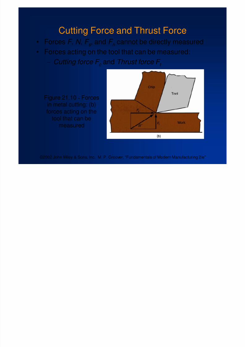
Cutting Force and Thrust Force•
Forces F , N , F s , and F n cannot be directly measured• Forces acting on the tool that can be measured:
Cutting force F c and Thrust force F t
Figure 21.10 - Forcesin metal cutting: (b)forces acting on the
tool that can bemeasured

8/4/2019 Ch21 Metal Cutting Theory Wiley
http://slidepdf.com/reader/full/ch21-metal-cutting-theory-wiley 33/44
©2002 John Wiley & Sons, Inc. M. P. Groover, “Fundamentals of Modern Manufacturing 2/e”
Forces in Metal Cutting
• Equations can be derived to relate the forces thatcannot be measured to the forces that can bemeasured:
F = F c sin + F t cos N = F c cos - F t sin
F s = F c cos - F t sin
F n = F c sin + F t cos
• Based on these calculated force, shear stress andcoefficient of friction can be determined

8/4/2019 Ch21 Metal Cutting Theory Wiley
http://slidepdf.com/reader/full/ch21-metal-cutting-theory-wiley 34/44
©2002 John Wiley & Sons, Inc. M. P. Groover, “Fundamentals of Modern Manufacturing 2/e”
The Merchant Equation
• Of all the possible angles at which shear deformationcould occur, the work material will select a shear
plane angle which minimizes energy, given by
• Derived by Eugene Merchant
• Based on orthogonal cutting, but validity extends to3-D machining
2245

8/4/2019 Ch21 Metal Cutting Theory Wiley
http://slidepdf.com/reader/full/ch21-metal-cutting-theory-wiley 35/44
©2002 John Wiley & Sons, Inc. M. P. Groover, “Fundamentals of Modern Manufacturing 2/e”
What the Merchant Equation Tells Us
•To increase shear plane angle Increase the rake angle
Reduce the friction angle (or coefficient of friction)
2245

8/4/2019 Ch21 Metal Cutting Theory Wiley
http://slidepdf.com/reader/full/ch21-metal-cutting-theory-wiley 36/44
©2002 John Wiley & Sons, Inc. M. P. Groover, “Fundamentals of Modern Manufacturing 2/e”
• Higher shear plane angle means smaller shear planewhich means lower shear force
•Result: lower cutting forces, power, temperature, allof which mean easier machining
Figure 21.12 - Effect of shear plane angle : (a) higher with a
resulting lower shear plane area; (b) smaller with a correspondinglarger shear plane area. Note that the rake angle is larger in (a), whichtends to increase shear angle according to the Merchant equation

8/4/2019 Ch21 Metal Cutting Theory Wiley
http://slidepdf.com/reader/full/ch21-metal-cutting-theory-wiley 37/44
©2002 John Wiley & Sons, Inc. M. P. Groover, “Fundamentals of Modern Manufacturing 2/e”
Power and Energy Relationships
• A machining operation requires power
The power to perform machining can be computed from:
P c = F c v
where P c = cutting power; F c = cutting force; and v =cutting speed

8/4/2019 Ch21 Metal Cutting Theory Wiley
http://slidepdf.com/reader/full/ch21-metal-cutting-theory-wiley 38/44
©2002 John Wiley & Sons, Inc. M. P. Groover, “Fundamentals of Modern Manufacturing 2/e”
Power and Energy Relationships
In U.S. customary units, power is traditional expressedas horsepower (dividing ft-lb/min by 33,000)
where HP c = cutting horsepower, hp
00033,
v F
HP c
c

8/4/2019 Ch21 Metal Cutting Theory Wiley
http://slidepdf.com/reader/full/ch21-metal-cutting-theory-wiley 39/44
©2002 John Wiley & Sons, Inc. M. P. Groover, “Fundamentals of Modern Manufacturing 2/e”
Power and Energy Relationships
Gross power to operate the machine tool P g or HP g isgiven by
or
where E = mechanical efficiency of machine tool
• Typical E for machine tools = 90%
E
P P c g E
HP HP c g

8/4/2019 Ch21 Metal Cutting Theory Wiley
http://slidepdf.com/reader/full/ch21-metal-cutting-theory-wiley 40/44
©2002 John Wiley & Sons, Inc. M. P. Groover, “Fundamentals of Modern Manufacturing 2/e”
Unit Power in Machining
• Useful to convert power into power per unit volumerate of metal cut
• Called the unit power , P u or unit horsepower , HP u
or
where MRR = material removal rate
MRR
P P c
u MRR
HP HP c
u

8/4/2019 Ch21 Metal Cutting Theory Wiley
http://slidepdf.com/reader/full/ch21-metal-cutting-theory-wiley 41/44
©2002 John Wiley & Sons, Inc. M. P. Groover, “Fundamentals of Modern Manufacturing 2/e”
Specific Energy in Machining
Unit power is also known as the specific energy U
Units for specific energy are typically N-m/mm3 or J/mm3
(in-lb/in3)
w t
F
w vt
v
MRR
P P U
o
c
o
c c
u

8/4/2019 Ch21 Metal Cutting Theory Wiley
http://slidepdf.com/reader/full/ch21-metal-cutting-theory-wiley 42/44
©2002 John Wiley & Sons, Inc. M. P. Groover, “Fundamentals of Modern Manufacturing 2/e”
Cutting Temperature
• Approximately 98% of the energy in machining isconverted into heat
• This can cause temperatures to be very high at the
tool-
chip• The remaining energy (about 2%) is retained as
elastic energy in the chip

8/4/2019 Ch21 Metal Cutting Theory Wiley
http://slidepdf.com/reader/full/ch21-metal-cutting-theory-wiley 43/44
©2002 John Wiley & Sons, Inc. M. P. Groover, “Fundamentals of Modern Manufacturing 2/e”
Cutting Temperature
• Several analytical methods to calculate cuttingtemperature
• Method by N. Cook derived from dimensionalanalysis using experimental data for various workmaterials
where T = temperature rise at tool-chip interface; U =specific energy; v = cutting speed; t o = chip thickness
before cut; C = volumetric specific heat of workmaterial; K = thermal diffusivity of the work material
333040
..
K
vt
C
U T o

8/4/2019 Ch21 Metal Cutting Theory Wiley
http://slidepdf.com/reader/full/ch21-metal-cutting-theory-wiley 44/44
©2002 John Wiley & Sons, Inc. M. P. Groover, “Fundamentals of Modern Manufacturing 2/e”
Cutting Temperature
• Experimental methods can be used to measuretemperatures in machining
• Most frequently used technique is the tool - chip
thermocouple • Using this method, K. Trigger determined the
speed-temperature relationship to be of the form:
T = K v m
where T = measured tool-chip interface temperature