Ch15
32
Chapter 15 Enhanced Switched Technologies THE FOLLOWING ICND2 EXAM TOPICS ARE COVERED IN THIS CHAPTER: 1 LAN Switching Technologies ■ Identify enhanced switching technologies ■ RSTP ■ PVSTP ■ EtherChannels ■ Configure and verify PVSTP operation ■ describe root bridge election ■ spanning-tree mode 1 Troubleshooting ■ Troubleshoot and resolve spanning-tree operation issues ■ root switch ■ priority ■ mode is correct ■ port states ■ Troubleshoot EtherChannel problems
Transcript of Ch15
Chapter
15Enhanced Switched
Technologies
THE FOLLOWING ICND2 EXAM TOPICS
ARE COVERED IN THIS CHAPTER:
1 LAN Switching Technologies
■ Identify enhanced switching technologies
■ RSTP
■ PVSTP
■ EtherChannels
■ Configure and verify PVSTP operation
■ describe root bridge election
■ spanning-tree mode
1 Troubleshooting
■ Troubleshoot and resolve spanning-tree operation issues
■ root switch
■ priority
■ mode is correct
■ port states
■ Troubleshoot EtherChannel problems
Long ago, a company called Digital Equipment Corporation
(DEC) created the original version of Spanning Tree Protocol
(STP). The IEEE later created its own version of STP called
802.1d. Cisco has moved toward another industry standard in its newer switches called 802.1w.
We’ll explore both the old and new versions of STP in this chapter, but "rst, I’ll de"ne some
important STP basics.
Routing protocols like RIP and OSPF have processes for preventing loops from occur-
ring at the Network layer, but if you have redundant physical links between your switches,
these protocols won’t do a thing to stop loops from occurring at the Data Link layer. That’s
exactly why STP was developed—to put an end to loop issues in a layer 2 switched network.
It’s also why we’ll be thoroughly exploring the key features of this vital protocol as well as
how it works within a switched network in this chapter.
After covering STP in detail, we’ll move on to explore EtherChannel.
To find up-to-the-minute updates for this chapter, please see www.lammle
.com/forum or the book’s web page at www.sybex.com.
Spanning Tree Protocol (STP)
Spanning Tree Protocol (STP) achieves its primary objective of preventing network loops on
layer 2 network bridges or switches by monitoring the network to track all links and shut
down the redundant ones. STP uses the spanning-tree algorithm (STA) to "rst create a topol-
ogy database and then search out and disable redundant links. With STP running, frames
will be forwarded on only premium, STP-chosen links.
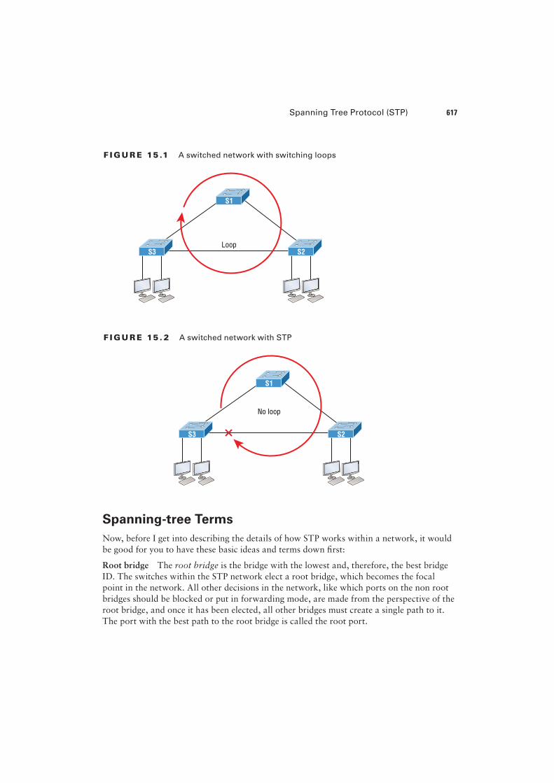
The Spanning Tree Protocol is a great protocol to use in networks like the one shown in
Figure 15.1.
This is a switched network with a redundant topology that includes switching loops.
Without some type of layer 2 mechanism in place to prevent a network loop, this network
is vulnerable to nasty issues like broadcast storms, multiple frame copies, and MAC table
thrashing! Figure 15.2 shows how this network would work with STP working on the
switches.
There a few types of spanning-tree protocols, but I’ll start with the IEEE version 802.1d,
which happens to be the default on all Cisco IOS switches.
Spanning Tree Protocol (STP) 617
F I GU R E 15 .1 A switched network with switching loops
S1
S3 S2Loop
F I GU R E 15 . 2 A switched network with STP
S1
No loop
S3 S2
Spanning-tree Terms
Now, before I get into describing the details of how STP works within a network, it would
be good for you to have these basic ideas and terms down �rst:
Root bridge The root bridge is the bridge with the lowest and, therefore, the best bridge
ID. The switches within the STP network elect a root bridge, which becomes the focal
point in the network. All other decisions in the network, like which ports on the non root
bridges should be blocked or put in forwarding mode, are made from the perspective of the
root bridge, and once it has been elected, all other bridges must create a single path to it.
The port with the best path to the root bridge is called the root port.
618 Chapter 15 u Enhanced Switched Technologies
Non-root bridges These are all bridges that aren’t the root bridge. Non-root bridges
exchange BPDUs with all the other bridges and update the STP topology database on all
switches. This prevents loops and helps defend against link failures.
BPDU All switches exchange information to use for the subsequent con�guration of the
network. Each switch compares the parameters in the Bridge Protocol Data Unit (BPDU)
that it sends to a neighbor with the parameters in the BPDU that it receives from other
neighbors. Inside the BPDU is the bridge ID.
Bridge ID The bridge ID is how STP keeps track of all the switches in the network. It’s
determined by a combination of the bridge priority, which is 32,768 by default on all Cisco
switches, and the base MAC address. The bridge with the lowest bridge ID becomes the
root bridge in the network. Once the root bridge is established, every other switch must
make a single path to it. Most networks bene�t by forcing a speci�c bridge or switch to be
on the Root Bridge by setting its bridge priority lower than the default value.
Port cost Port cost determines the best path when multiple links are used between two
switches. The cost of a link is determined by the bandwidth of a link, and this path cost is
the deciding factor used by every bridge to �nd the most ef�cient path to the root bridge.
Path cost A switch may encounter one or more switches on its path to the Root Bridge, and
there may be more than one possible path. All unique paths are analyzed individually, and a
path cost is calculated for each unique path by adding the individual port costs encountered
on the way to the Root Bridge.
Bridge Port Roles
STP uses roles to determine how a port on a switch will act within the spanning-tree
algorithm.
Root port The root port is the link with the lowest path cost to the root bridge. If more
than one link connects to the root bridge, then a port cost is found by checking the band-
width of each link. The lowest-cost port becomes the root port. When multiple links con-
nect to the same device, the port connected to the lowest port number on the upstream
switch will be the one that’s used. The root bridge can never have a root port designation,
while every other switch in a network must have one and only one root port.
Designated port A designated port is one that’s been determined to have the best (lowest)
cost to get to on a given network segment, compared to other ports on that segment. A des-
ignated port will be marked as a forwarding port, and you can have only one forwarding
port per network segment.
Non-designated port A non-designated port is one with a higher cost than the designated
port. These are basically the ones left over after the root ports and designated ports have
been determined. Non-designated ports are put in blocking or discarding mode—they are
not forwarding ports!
Forwarding port A forwarding port forwards frames and will be either a root port or a
designated port.
Spanning Tree Protocol (STP) 619
Blocked port A blocked port won’t forward frames in order to prevent loops. A blocked
port will still always listen to BPDU frames from neighbor switches, but it will drop any
and all other frames received and will never transmit a frame.
Alternate port This corresponds to the blocking state of 802.1d, and is a term used with
the newer 802.1w (Cisco Rapid Spanning Tree Protocol). An alternative port is located on a
switch connected to a LAN segment with two or more switches connected, and one of the
other switches holds the designated port.
Backup port This corresponds to the blocking state of 802.1d, and is a term now used
with the newer 802.1w. A backup port is connected to a LAN segment where another port
on that switch is acting as the designated port.
Spanning-tree Port States
Okay, so you plug your host into a switch port and the light turns amber and your host doesn’t
get a DHCP address from the server. You wait and wait and �nally the light goes green after
almost a full minute—that’s an eternity in today’s networks! This is the STA transitioning
through the different port states verifying that you didn’t just create a loop with the device you
just plugged in. STP would rather time out your new host than allow a loop into the network
because that would effectively bring your network to its knees. Let’s talk about the transition
states; then later in this chapter we’ll talk about how to speed this process up.
The ports on a bridge or switch running IEEE 802.1d STP can transition through �ve
different states:
Disabled (technically, not a transition state) A port in the administratively disabled state
doesn’t participate in frame forwarding or STP. A port in the disabled state is virtually
nonoperational.
Blocking As I mentioned, a blocked port won’t forward frames; it just listens to BPDUs.
The purpose of the blocking state is to prevent the use of looped paths. All ports are in
blocking state by default when the switch is powered up.
Listening This port listens to BPDUs to make sure no loops occur on the network before
passing data frames. A port in listening state prepares to forward data frames without
populating the MAC address table.
Learning The switch port listens to BPDUs and learns all the paths in the switched net-
work. A port in learning state populates the MAC address table but still doesn’t forward
data frames. Forward delay refers to the time it takes to transition a port from listening to
learning mode, or from learning to forwarding mode, which is set to 15 seconds by default
and can be seen in the show spanning-tree output.
Forwarding This port sends and receives all data frames on the bridged port. If the port is
still a designated or root port at the end of the learning state, it will enter the forwarding state.
Switches populate the MAC address table in learning and forwarding
modes only.
620 Chapter 15 u Enhanced Switched Technologies
Switch ports are most often in either the blocking or forwarding state. A forwarding
port is typically the one that’s been determined to have the lowest (best) cost to the root
bridge. But when and if the network experiences a topology change due to a failed link or
because someone has added in a new switch, you’ll see the ports on a switch transitioning
through listening and learning states.
As I said earlier, blocking ports is a strategy for preventing network loops. Once a
switch determines the best path to the root bridge for its root port and any designated
ports, all other redundant ports will be in blocking mode. Blocked ports can still receive
BPDUs—they just don’t send out any frames.
If a switch determines that a blocked port should become the designated or root port
because of a topology change, it will go into listening mode and check all BPDUs it receives
to make sure it won’t create a loop once the port moves into forwarding mode.
Convergence
Convergence occurs when all ports on bridges and switches have transitioned to either for-
warding or blocking modes. No data will be forwarded until convergence is complete. Yes—
you read that right: When STP is converging, all host data stops transmitting through the
switches! So if you want to remain on speaking terms with your network’s users, or remain
employed for any length of time, you must make sure that your switched network is physi-
cally designed really well so that STP can converge quickly!
Convergence is vital because it ensures that all devices have a coherent database. And
making sure this happens ef�ciently will de�nitely require your time and attention. The
original STP (802.1d) takes 50 seconds to go from blocking to forwarding mode by default
and I don’t recommend changing the default STP timers. You can adjust those timers for a
large network, but the better solution is simply to opt out of using 802.1d at all! We’ll get
to the various STP versions in a minute.
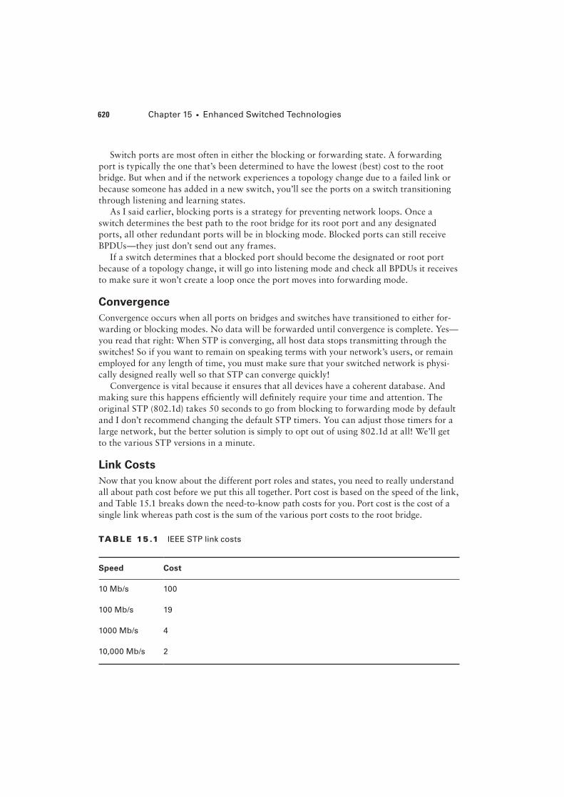
Link Costs
Now that you know about the different port roles and states, you need to really understand
all about path cost before we put this all together. Port cost is based on the speed of the link,
and Table 15.1 breaks down the need-to-know path costs for you. Port cost is the cost of a
single link whereas path cost is the sum of the various port costs to the root bridge.
TA B LE 15 .1 IEEE STP link costs
Speed Cost
10 Mb/s 100
100 Mb/s 19
1000 Mb/s 4
10,000 Mb/s 2
Spanning Tree Protocol (STP) 621
These costs will be used in the STP calculations to choose a single root port on each
bridge. You absolutely need to memorize this table, but no worries—I’ll guide you through
lots of examples in this chapter to help you do that quite easily! Now it’s time to take every-
thing we’ve learned so far and put it all together.
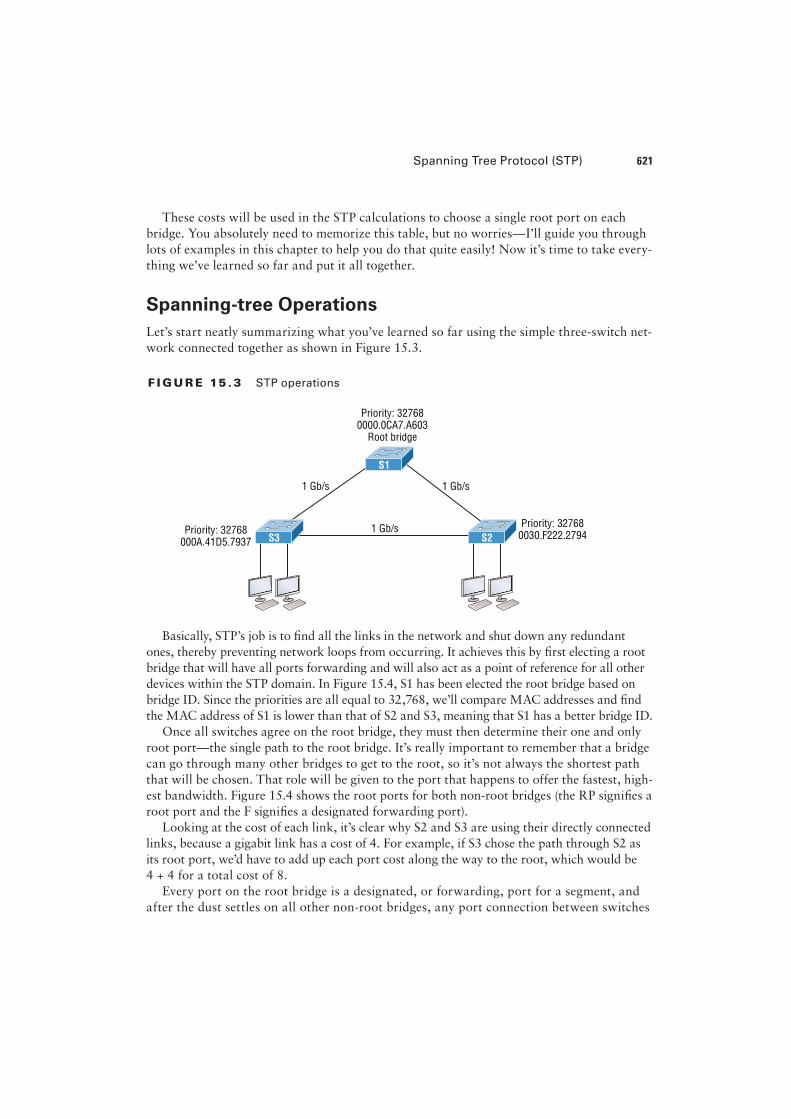
Spanning-tree Operations
Let’s start neatly summarizing what you’ve learned so far using the simple three-switch net-
work connected together as shown in Figure 15.3.
F I GU R E 15 . 3 STP operations
Priority: 327680000.0CA7.A603
Root bridge
1 Gb/s
1 Gb/s 1 Gb/s
Priority: 32768000A.41D5.7937
Priority: 327680030.F222.2794
S1
S3 S2
Basically, STP’s job is to �nd all the links in the network and shut down any redundant
ones, thereby preventing network loops from occurring. It achieves this by �rst electing a root
bridge that will have all ports forwarding and will also act as a point of reference for all other
devices within the STP domain. In Figure 15.4, S1 has been elected the root bridge based on
bridge ID. Since the priorities are all equal to 32,768, we’ll compare MAC addresses and �nd
the MAC address of S1 is lower than that of S2 and S3, meaning that S1 has a better bridge ID.
Once all switches agree on the root bridge, they must then determine their one and only
root port—the single path to the root bridge. It’s really important to remember that a bridge
can go through many other bridges to get to the root, so it’s not always the shortest path
that will be chosen. That role will be given to the port that happens to offer the fastest, high-
est bandwidth. Figure 15.4 shows the root ports for both non-root bridges (the RP signi�es a
root port and the F signi�es a designated forwarding port).
Looking at the cost of each link, it’s clear why S2 and S3 are using their directly connected
links, because a gigabit link has a cost of 4. For example, if S3 chose the path through S2 as
its root port, we’d have to add up each port cost along the way to the root, which would be
4 + 4 for a total cost of 8.
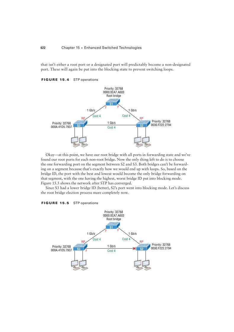
Every port on the root bridge is a designated, or forwarding, port for a segment, and
after the dust settles on all other non-root bridges, any port connection between switches
622 Chapter 15 u Enhanced Switched Technologies
that isn’t either a root port or a designated port will predictably become a non-designated
port. These will again be put into the blocking state to prevent switching loops.
F I GU R E 15 . 4 STP operations
FF
Priority: 327680000.0CA7.A603
Root bridge
1 Gb/s
Cost 4
1 Gb/s 1 Gb/s
RPCost 4
Priority: 32768000A.41D5.7937
RPCost 4
Priority: 327680030.F222.2794
S1
S3 S2
Okay—at this point, we have our root bridge with all ports in forwarding state and we’ve
found our root ports for each non-root bridge. Now the only thing left to do is to choose
the one forwarding port on the segment between S2 and S3. Both bridges can’t be forward-
ing on a segment because that’s exactly how we would end up with loops. So, based on the
bridge ID, the port with the best and lowest would become the only bridge forwarding on
that segment, with the one having the highest, worst bridge ID put into blocking mode.
Figure 15.5 shows the network after STP has converged.
Since S3 had a lower bridge ID (better), S2’s port went into blocking mode. Let’s discuss
the root bridge election process more completely now.
F I GU R E 15 .5 STP operations
FF
Priority: 327680000.0CA7.A603
Root bridge
1 Gb/s
Cost 4
1 Gb/s 1 Gb/s
RP
F
Cost 4
Priority: 32768000A.41D5.7937
RPCost 4
Priority: 327680030.F222.2794
S1
S3 S2
Types of Spanning-tree Protocols 623
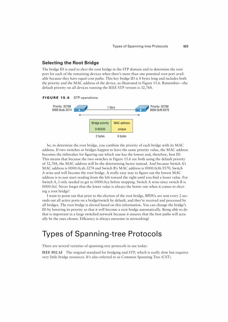
Selecting the Root Bridge
The bridge ID is used to elect the root bridge in the STP domain and to determine the root
port for each of the remaining devices when there’s more than one potential root port avail-
able because they have equal-cost paths. This key bridge ID is 8 bytes long and includes both
the priority and the MAC address of the device, as illustrated in Figure 15.6. Remember—the
default priority on all devices running the IEEE STP version is 32,768.
F I GU R E 15 .6 STP operations
1 Gb/sPriority: 327680000.0cab.3274
Priority: 327680000.0cf6.9370A B
Bridge priority MAC address
0-65535 unique
2 bytes 6 bytes
So, to determine the root bridge, you combine the priority of each bridge with its MAC
address. If two switches or bridges happen to have the same priority value, the MAC address
becomes the tiebreaker for �guring out which one has the lowest and, therefore, best ID.
This means that because the two switches in Figure 15.6 are both using the default priority
of 32,768, the MAC address will be the determining factor instead. And because Switch A’s
MAC address is 0000.0cab.3274 and Switch B’s MAC address is 0000.0cf6.9370, Switch
A wins and will become the root bridge. A really easy way to �gure out the lowest MAC
address is to just start reading from the left toward the right until you �nd a lesser value. For
Switch A, I only needed to get to 0000.0ca before stopping. Switch A wins since switch B is
0000.0cf. Never forget that the lower value is always the better one when it comes to elect-
ing a root bridge!
I want to point out that prior to the election of the root bridge, BPDUs are sent every 2 sec-
onds out all active ports on a bridge/switch by default, and they’re received and processed by
all bridges. The root bridge is elected based on this information. You can change the bridge’s
ID by lowering its priority so that it will become a root bridge automatically. Being able to do
that is important in a large switched network because it ensures that the best paths will actu-
ally be the ones chosen. Ef�ciency is always awesome in networking!
Types of Spanning-tree Protocols
There are several varieties of spanning-tree protocols in use today:
IEEE 802.1d The original standard for bridging and STP, which is really slow but requires
very little bridge resources. It’s also referred to as Common Spanning Tree (CST).
624 Chapter 15 u Enhanced Switched Technologies
PVST+ The Cisco proprietary enhancement for STP that provides a separate 802.1d span-
ning-tree instance for each VLAN. Know that this is just as slow as the CST protocol, but
with it, we get to have multiple root bridges. This creates more ef�ciency of the links in the
network, but it does use more bridge resources than CST does.
IEEE 802.1w Also called Rapid Spanning Tree Protocol (RSTP), this iteration enhanced
the BPDU exchange and paved the way for much faster network convergence, but it still
only allows for one root bridge per network like CST. The bridge resources used with RSTP
are higher than CST’s but less than PVST+.
Rapid PVST+ Cisco’s version of RSTP that also uses PVST+ and provides a separate
instance of 802.1w per VLAN. It gives us really fast convergence times and optimal traf�c
#ow but predictably requires the most CPU and memory of all.
Common Spanning Tree
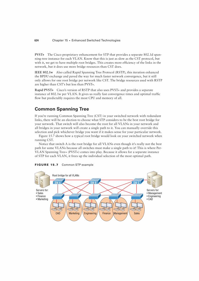
If you’re running Common Spanning Tree (CST) in your switched network with redundant
links, there will be an election to choose what STP considers to be the best root bridge for
your network. That switch will also become the root for all VLANs in your network and
all bridges in your network will create a single path to it. You can manually override this
selection and pick whichever bridge you want if it makes sense for your particular network.
Figure 15.7 shows how a typical root bridge would look on your switched network when
running CST.
Notice that switch A is the root bridge for all VLANs even though it’s really not the best
path for some VLANs because all switches must make a single path to it! This is where Per-
VLAN Spanning Tree+ (PVST+) comes into play. Because it allows for a separate instance
of STP for each VLAN, it frees up the individual selection of the most optimal path.
F I GU R E 15 .7 Common STP example
CAD Marketing
Servers for: Servers for:
SW-B SW-CSW-A
Types of Spanning-tree Protocols 625
Per-VLAN Spanning Tree+
PVST+ is a Cisco proprietary extension to 801.2d STP that provides a separate 802.1
spanning-tree instance for each VLAN con�gured on your switches. All of Cisco pro-
prietary extensions were created to improve convergence times, which is 50 seconds by
default. Cisco IOS switches run 802.1d PVST+ by default, which means you’ll have opti-
mal path selection, but the convergence time will still be slow.
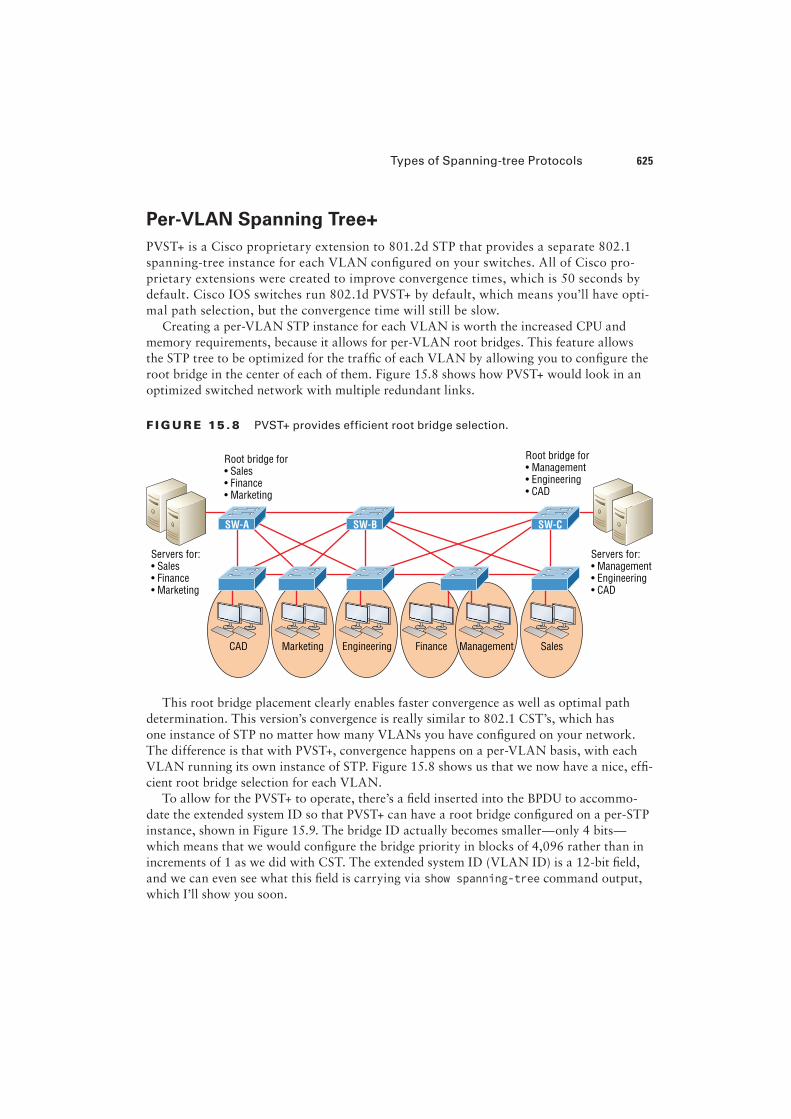
Creating a per-VLAN STP instance for each VLAN is worth the increased CPU and
memory requirements, because it allows for per-VLAN root bridges. This feature allows
the STP tree to be optimized for the traf�c of each VLAN by allowing you to con�gure the
root bridge in the center of each of them. Figure 15.8 shows how PVST+ would look in an
optimized switched network with multiple redundant links.
F I GU R E 15 . 8 PVST+ provides efficient root bridge selection.
CAD Marketing
Servers for: Servers for:
SW-B SW-CSW-A
Root bridge for Root bridge for
This root bridge placement clearly enables faster convergence as well as optimal path
determination. This version’s convergence is really similar to 802.1 CST’s, which has
one instance of STP no matter how many VLANs you have con�gured on your network.
The difference is that with PVST+, convergence happens on a per-VLAN basis, with each
VLAN running its own instance of STP. Figure 15.8 shows us that we now have a nice, ef�-
cient root bridge selection for each VLAN.
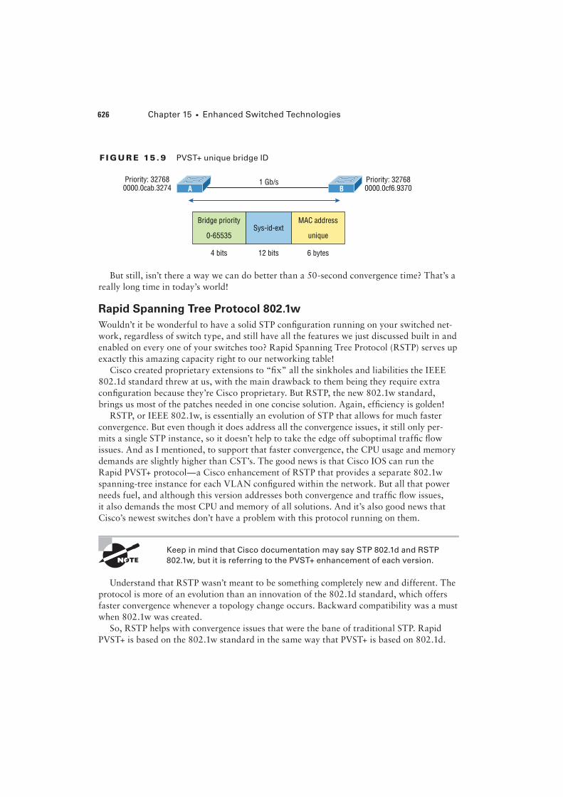
To allow for the PVST+ to operate, there’s a �eld inserted into the BPDU to accommo-
date the extended system ID so that PVST+ can have a root bridge con�gured on a per-STP
instance, shown in Figure 15.9. The bridge ID actually becomes smaller—only 4 bits—
which means that we would con�gure the bridge priority in blocks of 4,096 rather than in
increments of 1 as we did with CST. The extended system ID (VLAN ID) is a 12-bit �eld,
and we can even see what this �eld is carrying via show spanning-tree command output,
which I’ll show you soon.
626 Chapter 15 u Enhanced Switched Technologies
F I GU R E 15 . 9 PVST+ unique bridge ID
1 Gb/sPriority: 327680000.0cab.3274
Priority: 327680000.0cf6.9370A B
Bridge priority MAC address
0-65535 unique
4 bits 6 bytes
Sys-id-ext
12 bits
But still, isn’t there a way we can do better than a 50-second convergence time? That’s a
really long time in today’s world!
Rapid Spanning Tree Protocol 802.1w
Wouldn’t it be wonderful to have a solid STP con�guration running on your switched net-
work, regardless of switch type, and still have all the features we just discussed built in and
enabled on every one of your switches too? Rapid Spanning Tree Protocol (RSTP) serves up
exactly this amazing capacity right to our networking table!
Cisco created proprietary extensions to “�x” all the sinkholes and liabilities the IEEE
802.1d standard threw at us, with the main drawback to them being they require extra
con�guration because they’re Cisco proprietary. But RSTP, the new 802.1w standard,
brings us most of the patches needed in one concise solution. Again, ef�ciency is golden!
RSTP, or IEEE 802.1w, is essentially an evolution of STP that allows for much faster
convergence. But even though it does address all the convergence issues, it still only per-
mits a single STP instance, so it doesn’t help to take the edge off suboptimal traf�c #ow
issues. And as I mentioned, to support that faster convergence, the CPU usage and memory
demands are slightly higher than CST’s. The good news is that Cisco IOS can run the
Rapid PVST+ protocol—a Cisco enhancement of RSTP that provides a separate 802.1w
spanning-tree instance for each VLAN con�gured within the network. But all that power
needs fuel, and although this version addresses both convergence and traf�c #ow issues,
it also demands the most CPU and memory of all solutions. And it’s also good news that
Cisco’s newest switches don’t have a problem with this protocol running on them.
Keep in mind that Cisco documentation may say STP 802.1d and RSTP
802.1w, but it is referring to the PVST+ enhancement of each version.
Understand that RSTP wasn’t meant to be something completely new and different. The
protocol is more of an evolution than an innovation of the 802.1d standard, which offers
faster convergence whenever a topology change occurs. Backward compatibility was a must
when 802.1w was created.
So, RSTP helps with convergence issues that were the bane of traditional STP. Rapid
PVST+ is based on the 802.1w standard in the same way that PVST+ is based on 802.1d.
Types of Spanning-tree Protocols 627
The operation of Rapid PVST+ is simply a separate instance of 802.1w for each VLAN.
Here’s a list to clarify how this all breaks down:
u RSTP speeds the recalculation of the spanning tree when the layer 2 network topology
changes.
u It’s an IEEE standard that redefines STP port roles, states, and BPDUs.
u RSTP is extremely proactive and very quick, so it doesn’t need the 802.1d delay timers.
u RSTP (802.1w) supersedes 802.1d while remaining backward compatible.
u Much of the 802.1d terminology and most parameters remain unchanged.
u 802.1w is capable of reverting to 802.1d to interoperate with traditional switches on a
per-port basis.
And to clear up confusion, there are also �ve terminology adjustments between 802.1d’s
�ve port states to 802.1w’s, compared here, respectively:
802.1d State 802.1w State
Disabled = Discarding
Blocking = Discarding
Listening = Discarding
Learning = Learning
Forwarding = Forwarding
Make note of the fact that RSTP basically just goes from discarding to learning to for-
warding, whereas 802.1d requires �ve states to transition.
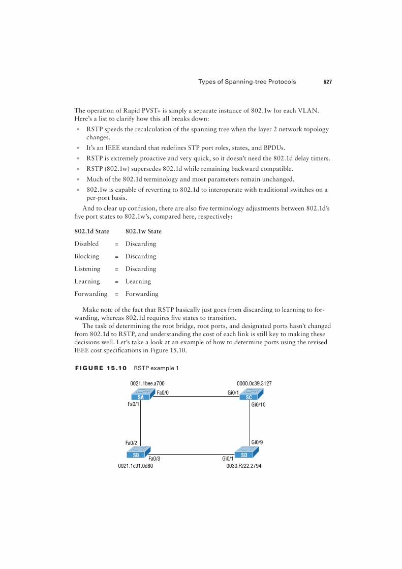
The task of determining the root bridge, root ports, and designated ports hasn’t changed
from 802.1d to RSTP, and understanding the cost of each link is still key to making these
decisions well. Let’s take a look at an example of how to determine ports using the revised
IEEE cost speci�cations in Figure 15.10.
F I GU R E 15 .10 RSTP example 1
SB SD
SA SC
0021.1bee.a700 0000.0c39.3127
0021.1c91.0d80 0030.F222.2794
Fa0/1
Fa0/2
Fa0/3 Gi0/1
Fa0/0 Gi0/1
Gi0/10
Gi0/9
628 Chapter 15 u Enhanced Switched Technologies
Can you �gure out which is the root bridge? How about which port is the root and
which ones are designated? Well, because SC has the lowest MAC address, it becomes the
root bridge, and since all ports on a root bridge are forwarding designated ports, well,
that’s easy, right? Ports Gi0/1 and Gi0/10 become designated forwarding ports on SC.
But which one would be the root port for SA? To �gure that out, we must �rst �nd the port
cost for the direct link between SA and SC. Even though the root bridge (SC) has a Gigabit
Ethernet port, it’s running at 100 Mbps because SA’s port is a 100-Mbps port, giving it a cost
of 19. If the paths between SA and SC were both Gigabit Ethernet, their costs would only be 4,
but because they’re running 100 Mbps links instead, the cost jumps to a whopping 19!
Can you �nd SD’s root port? A quick glance at the link between SC and SD tells us that’s
a Gigabit Ethernet link with a cost of 4, so the root port for SD would be its GI0/9 port.
The cost of the link between SB and SD is also 19 because it’s also a Fast Ethernet link,
bringing the full cost from SB to SD to the root (SC) to a total cost of 19 + 4 = 23. If SB
were to go through SA to get to SC, then the cost would be 19 + 19, or 38, so the root port
of SB becomes the Fa0/3 port.
The root port for SA would be the Fa0/0 port since that’s a direct link with a cost of 19.
Going through SB to SD would be 19 + 19 + 4 = 42, so we’ll use that as a backup link for
SA to get to the root just in case we need to.
Now, all we need is a forwarding port on the link between SA and SB. Because SA has
the lowest bridge ID, Fa0/1 on SA wins that role. Also, the Gi0/1 port on SD would become
a designated forwarding port. This is because the SB Fa0/3 port is a designed root port and
you must have a forwarding port on a network segment! This leaves us with the Fa0/2 port
on SB. Since it isn’t a root port or designated forwarding port, it will be placed into block-
ing mode, which will prevent looks in our network.
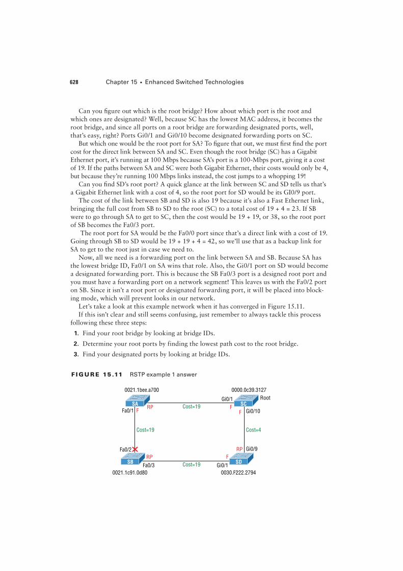
Let’s take a look at this example network when it has converged in Figure 15.11.
If this isn’t clear and still seems confusing, just remember to always tackle this process
following these three steps:
1. Find your root bridge by looking at bridge IDs.
2. Determine your root ports by finding the lowest path cost to the root bridge.
3. Find your designated ports by looking at bridge IDs.
F I GU R E 15 .11 RSTP example 1 answer
Cost=19SB SD
Cost=19SA SC
0021.1bee.a700 0000.0c39.3127
Root
0021.1c91.0d80 0030.F222.2794
Fa0/1
Fa0/2
Fa0/3
Cost=19 Cost=4
Gi0/1
Gi0/1
Gi0/10
Gi0/9
RP
RP
RP
FF
F
F
Types of Spanning-tree Protocols 629
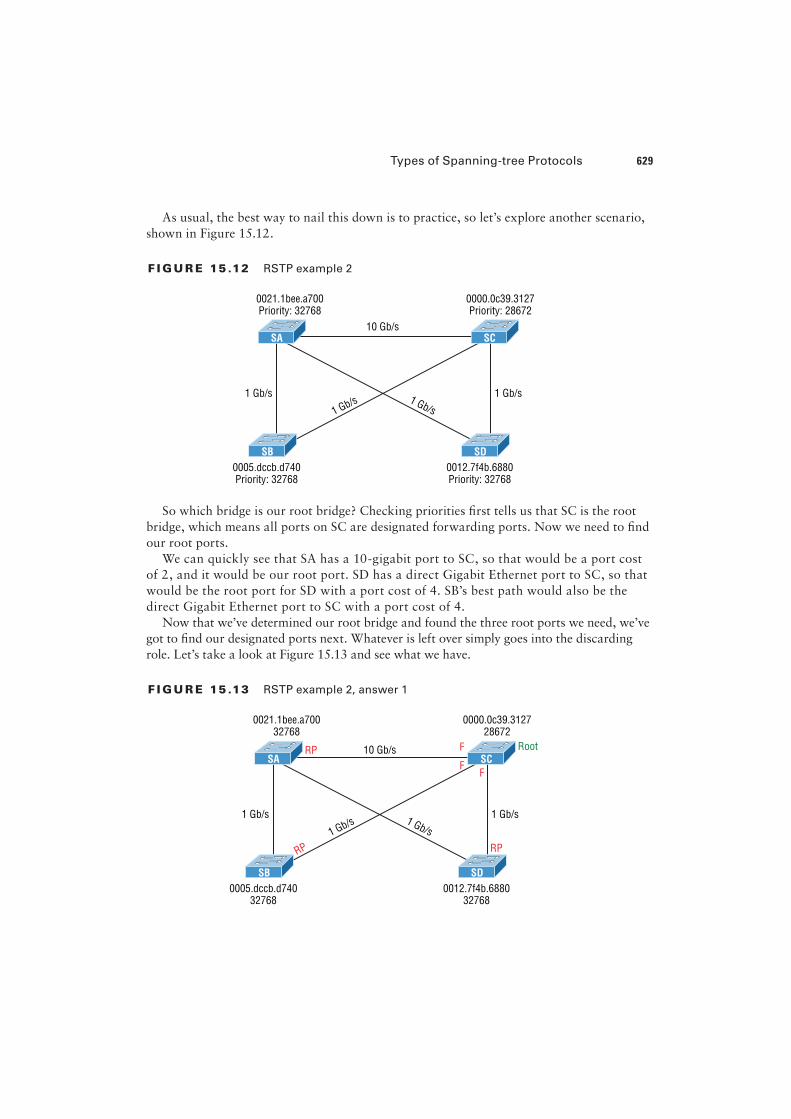
As usual, the best way to nail this down is to practice, so let’s explore another scenario,
shown in Figure 15.12.
F I GU R E 15 .12 RSTP example 2
SB SD
SA SC
0021.1bee.a700Priority: 32768
0000.0c39.3127Priority: 28672
0005.dccb.d740Priority: 32768
0012.7f4b.6880Priority: 32768
1 Gb/s
10 Gb/s
1 Gb/s
1 Gb/s 1 Gb/s
So which bridge is our root bridge? Checking priorities "rst tells us that SC is the root
bridge, which means all ports on SC are designated forwarding ports. Now we need to "nd
our root ports.
We can quickly see that SA has a 10-gigabit port to SC, so that would be a port cost
of 2, and it would be our root port. SD has a direct Gigabit Ethernet port to SC, so that
would be the root port for SD with a port cost of 4. SB’s best path would also be the
direct Gigabit Ethernet port to SC with a port cost of 4.
Now that we’ve determined our root bridge and found the three root ports we need, we’ve
got to "nd our designated ports next. Whatever is left over simply goes into the discarding
role. Let’s take a look at Figure 15.13 and see what we have.
F I GU R E 15 .13 RSTP example 2, answer 1
SB SD
SA SC
0021.1bee.a700
32768
0000.0c39.3127
28672
0005.dccb.d740
32768
0012.7f4b.6880
32768
RP
RPRP
F
FF
1 Gb/s1 Gb/s
10 Gb/s
1 Gb/s 1 Gb/s
Root
630 Chapter 15 u Enhanced Switched Technologies
All right, it looks like there are two links to choose between to "nd one designated port
per segment. Let’s start with the link between SA and SD. Which one has the best bridge ID?
They’re both running the same default priority, so by looking at the MAC address, we can
see that SD has the better bridge ID (lower), so the SA port toward SD will go into a discard-
ing role, or will it? The SD port will go into discarding mode, because the link from SA to
the root has the lowest accumulated path costs to the root bridge, and that is used before the
bridge ID in this circumstance. It makes sense to let the bridge with the fastest path to the
root bridge be a designated forwarding port. Let’s talk about this a little more in depth.
As you know, once your root bridge and root ports have been chosen, you’re left with
"nding your designated ports. Anything left over goes into discarding role. But how are the
designated ports chosen? Is it just bridge ID? Here are the rules:
1. To choose the switch that will forward on the segment, we select the switch with the low-
est accumulated path cost to the root bridge. We want the fast path to the root bridge.
2. If there is a tie on the accumulated path cost from both switches to the root bridge,
then we’ll use bridge ID, which was what we used in our previous example (but not
with this latest RSTP example; not with a 10-Gigabit Ethernet link to the root bridge
available!).
3. Port priorities can be set manually if we want a specific port chosen. The default prior-
ity is 32, but we can lower that if needed.
4. If there are two links between switches, and the bridge ID and priority are tied, the port
with the lowest number will be chosen—for example, Fa0/1 would be chosen over Fa0/2.
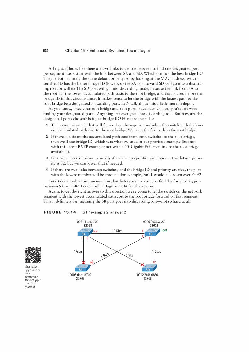
Let’s take a look at our answer now, but before we do, can you "nd the forwarding port
between SA and SB? Take a look at Figure 15.14 for the answer.
Again, to get the right answer to this question we’re going to let the switch on the network
segment with the lowest accumulated path cost to the root bridge forward on that segment.
This is de"nitely SA, meaning the SB port goes into discarding role—not so hard at all!
F I GU R E 15 .14 RSTP example 2, answer 2
SB SD
SA SC
0021.1bee.a700
32768
0000.0c39.3127
28672
0005.dccb.d740
32768
0012.7f4b.6880
32768
RP
RPRP
F
FFFF
1 Gb/s1 Gb/s
10 Gb/s
1 Gb/s 1 Gb/s
Root
Visit ccna .gg/ch15/a for a companion MicroNugget from CBT Nuggets.
Modifying and Verifying the Bridge ID 631
Modifying and Verifying the Bridge ID
To verify spanning tree on a Cisco switch, just use the command show spanning-tree.
From its output, we can determine our root bridge, priorities, root ports, and designated
and blocking/discarding ports.
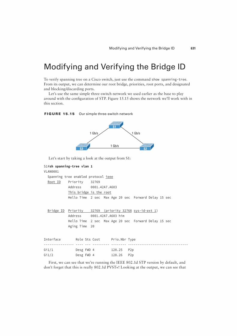
Let’s use the same simple three-switch network we used earlier as the base to play
around with the con"guration of STP. Figure 15.15 shows the network we’ll work with in
this section.
F I GU R E 15 .15 Our simple three-switch network
1 Gb/s
1 Gb/s 1 Gb/s
S1
S3 S2
Let’s start by taking a look at the output from S1:
S1#sh spanning-tree vlan 1
VLAN0001
Spanning tree enabled protocol ieee
Root ID Priority 32769
Address 0001.42A7.A603
This bridge is the root
Hello Time 2 sec Max Age 20 sec Forward Delay 15 sec
Bridge ID Priority 32769 (priority 32768 sys-id-ext 1)
Address 0001.42A7.A603 him
Hello Time 2 sec Max Age 20 sec Forward Delay 15 sec
Aging Time 20
Interface Role Sts Cost Prio.Nbr Type
---------------- ---- --- --------- -------- --------------------------------
Gi1/1 Desg FWD 4 128.25 P2p
Gi1/2 Desg FWD 4 128.26 P2p
First, we can see that we’re running the IEEE 802.1d STP version by default, and
don’t forget that this is really 802.1d PVST+! Looking at the output, we can see that
632 Chapter 15 u Enhanced Switched Technologies
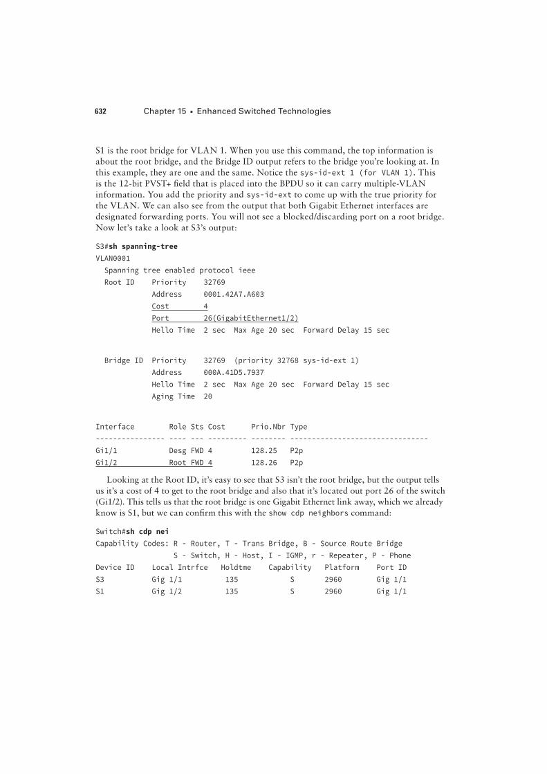
S1 is the root bridge for VLAN 1. When you use this command, the top information is
about the root bridge, and the Bridge ID output refers to the bridge you’re looking at. In
this example, they are one and the same. Notice the sys-id-ext 1 (for VLAN 1). This
is the 12-bit PVST+ "eld that is placed into the BPDU so it can carry multiple-VLAN
information. You add the priority and sys-id-ext to come up with the true priority for
the VLAN. We can also see from the output that both Gigabit Ethernet interfaces are
designated forwarding ports. You will not see a blocked/discarding port on a root bridge.
Now let’s take a look at S3’s output:
S3#sh spanning-tree
VLAN0001
Spanning tree enabled protocol ieee
Root ID Priority 32769
Address 0001.42A7.A603
Cost 4
Port 26(GigabitEthernet1/2)
Hello Time 2 sec Max Age 20 sec Forward Delay 15 sec
Bridge ID Priority 32769 (priority 32768 sys-id-ext 1)
Address 000A.41D5.7937
Hello Time 2 sec Max Age 20 sec Forward Delay 15 sec
Aging Time 20
Interface Role Sts Cost Prio.Nbr Type
---------------- ---- --- --------- -------- --------------------------------
Gi1/1 Desg FWD 4 128.25 P2p
Gi1/2 Root FWD 4 128.26 P2p
Looking at the Root ID, it’s easy to see that S3 isn’t the root bridge, but the output tells
us it’s a cost of 4 to get to the root bridge and also that it’s located out port 26 of the switch
(Gi1/2). This tells us that the root bridge is one Gigabit Ethernet link away, which we already
know is S1, but we can con"rm this with the show cdp neighbors command:
Switch#sh cdp nei
Capability Codes: R - Router, T - Trans Bridge, B - Source Route Bridge
S - Switch, H - Host, I - IGMP, r - Repeater, P - Phone
Device ID Local Intrfce Holdtme Capability Platform Port ID
S3 Gig 1/1 135 S 2960 Gig 1/1
S1 Gig 1/2 135 S 2960 Gig 1/1
Modifying and Verifying the Bridge ID 633
That’s how simple it is to "nd your root bridge if you don’t have the nice "gure as we
do. Use the show spanning-tree command, "nd your root port, and then use the show cdp
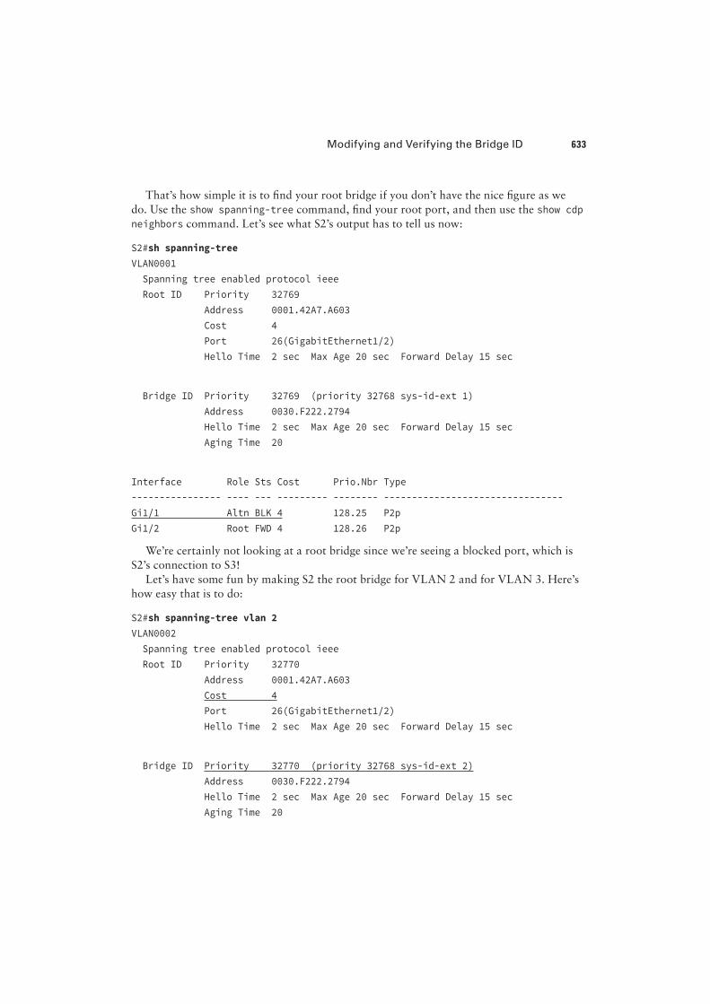
neighbors command. Let’s see what S2’s output has to tell us now:
S2#sh spanning-tree
VLAN0001
Spanning tree enabled protocol ieee
Root ID Priority 32769
Address 0001.42A7.A603
Cost 4
Port 26(GigabitEthernet1/2)
Hello Time 2 sec Max Age 20 sec Forward Delay 15 sec
Bridge ID Priority 32769 (priority 32768 sys-id-ext 1)
Address 0030.F222.2794
Hello Time 2 sec Max Age 20 sec Forward Delay 15 sec
Aging Time 20
Interface Role Sts Cost Prio.Nbr Type
---------------- ---- --- --------- -------- --------------------------------
Gi1/1 Altn BLK 4 128.25 P2p
Gi1/2 Root FWD 4 128.26 P2p
We’re certainly not looking at a root bridge since we’re seeing a blocked port, which is
S2’s connection to S3!
Let’s have some fun by making S2 the root bridge for VLAN 2 and for VLAN 3. Here’s
how easy that is to do:
S2#sh spanning-tree vlan 2
VLAN0002
Spanning tree enabled protocol ieee
Root ID Priority 32770
Address 0001.42A7.A603
Cost 4
Port 26(GigabitEthernet1/2)
Hello Time 2 sec Max Age 20 sec Forward Delay 15 sec
Bridge ID Priority 32770 (priority 32768 sys-id-ext 2)
Address 0030.F222.2794
Hello Time 2 sec Max Age 20 sec Forward Delay 15 sec
Aging Time 20
634 Chapter 15 u Enhanced Switched Technologies
Interface Role Sts Cost Prio.Nbr Type
---------------- ---- --- --------- -------- --------------------------------
Gi1/1 Altn BLK 4 128.25 P2p
Gi1/2 Root FWD 4 128.26 P2p
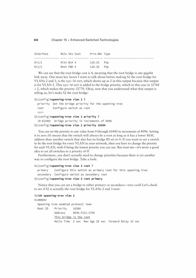
We can see that the root bridge cost is 4, meaning that the root bridge is one-gigabit
link away. One more key factor I want to talk about before making S2 the root bridge for
VLANs 2 and 3, is the sys-id-ext, which shows up as 2 in this output because this output
is for VLAN 2. This sys-id-ext is added to the bridge priority, which in this case in 32768
+ 2, which makes the priority 32770. Okay, now that you understand what that output is
telling us, let’s make S2 the root bridge:
S2(config)#spanning-tree vlan 2 ?
priority Set the bridge priority for the spanning tree
root Configure switch as root
<cr>
S2(config)#spanning-tree vlan 2 priority ?
<0-61440> bridge priority in increments of 4096
S2(config)#spanning-tree vlan 2 priority 16384
You can set the priority to any value from 0 through 61440 in increments of 4096. Setting
it to zero (0) means that the switch will always be a root as long as it has a lower MAC
address than another switch that also has its bridge ID set to 0. If you want to set a switch
to be the root bridge for every VLAN in your network, then you have to change the priority
for each VLAN, with 0 being the lowest priority you can use. But trust me—it’s never a good
idea to set all switches to a priority of 0!
Furthermore, you don’t actually need to change priorities because there is yet another
way to con"gure the root bridge. Take a look:
S2(config)#spanning-tree vlan 3 root ?
primary Configure this switch as primary root for this spanning tree
secondary Configure switch as secondary root
S2(config)#spanning-tree vlan 3 root primary
Notice that you can set a bridge to either primary or secondary—very cool! Let’s check
to see if S2 is actually the root bridge for VLANs 2 and 3 now:
S2#sh spanning-tree vlan 2
VLAN0002
Spanning tree enabled protocol ieee
Root ID Priority 16386
Address 0030.F222.2794
This bridge is the root
Hello Time 2 sec Max Age 20 sec Forward Delay 15 sec
Modifying and Verifying the Bridge ID 635
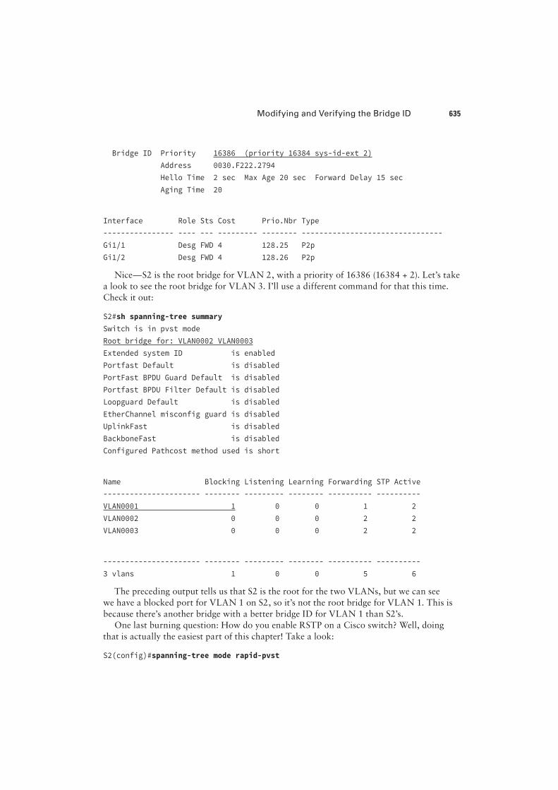
Bridge ID Priority 16386 (priority 16384 sys-id-ext 2)
Address 0030.F222.2794
Hello Time 2 sec Max Age 20 sec Forward Delay 15 sec
Aging Time 20
Interface Role Sts Cost Prio.Nbr Type
---------------- ---- --- --------- -------- --------------------------------
Gi1/1 Desg FWD 4 128.25 P2p
Gi1/2 Desg FWD 4 128.26 P2p
Nice—S2 is the root bridge for VLAN 2, with a priority of 16386 (16384 + 2). Let’s take
a look to see the root bridge for VLAN 3. I’ll use a different command for that this time.
Check it out:
S2#sh spanning-tree summary
Switch is in pvst mode
Root bridge for: VLAN0002 VLAN0003
Extended system ID is enabled
Portfast Default is disabled
PortFast BPDU Guard Default is disabled
Portfast BPDU Filter Default is disabled
Loopguard Default is disabled
EtherChannel misconfig guard is disabled
UplinkFast is disabled
BackboneFast is disabled
Configured Pathcost method used is short
Name Blocking Listening Learning Forwarding STP Active
---------------------- -------- --------- -------- ---------- ----------
VLAN0001 1 0 0 1 2
VLAN0002 0 0 0 2 2
VLAN0003 0 0 0 2 2
---------------------- -------- --------- -------- ---------- ----------
3 vlans 1 0 0 5 6
The preceding output tells us that S2 is the root for the two VLANs, but we can see
we have a blocked port for VLAN 1 on S2, so it’s not the root bridge for VLAN 1. This is
because there’s another bridge with a better bridge ID for VLAN 1 than S2’s.
One last burning question: How do you enable RSTP on a Cisco switch? Well, doing
that is actually the easiest part of this chapter! Take a look:
S2(config)#spanning-tree mode rapid-pvst
636 Chapter 15 u Enhanced Switched Technologies
Is that really all there is to it? Yes, because it’s a global command, not per VLAN. Let’s
verify we’re running RSTP now:
S2#sh spanning-tree
VLAN0001
Spanning tree enabled protocol rstp
Root ID Priority 32769
Address 0001.42A7.A603
Cost 4
Port 26(GigabitEthernet1/2)
Hello Time 2 sec Max Age 20 sec Forward Delay 15 sec
[output cut
S2#sh spanning-tree summary
Switch is in rapid-pvst mode
Root bridge for: VLAN0002 VLAN0003
Looks like we’re set! We’re running RSTP, S1 is our root bridge for VLAN 1, and S2 is the
root bridge for VLANs 2 and 3. I know this doesn’t seem hard, and it really isn’t, but you still
need to practice what we’ve covered so far in this chapter to really get your skills solid!
Spanning-tree Failure Consequences
Clearly, there will be consequences when a routing protocol fails on a single router, but
mainly, you’ll just lose connectivity to the networks directly connected to that router and it
usually does not affect the rest of your network. This de"nitely makes it easier to trouble-
shoot and "x the issue!
There are two failure types with STP. One of them causes the same type of issue I
mentioned with a routing protocol, when certain ports have been placed in a blocking
state they should be forwarding on a network segment instead. This situation makes the
network segment unusable, but the rest of the network will still be working. But what
happens when blocked ports are placed into forwarding state when they should be block-
ing? Let’s work through this second failure issue now, using the same layout we used in
the last section. Let’s start with Figure 15.16 and then "nd out what happens when STP
fails. Squeamish readers be warned—this isn’t pretty!
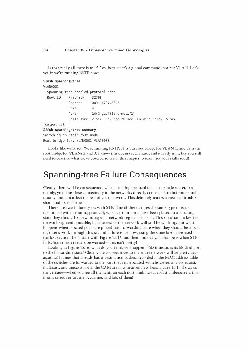
Looking at Figure 15.16, what do you think will happen if SD transitions its blocked port
to the forwarding state? Clearly, the consequences to the entire network will be pretty dev-
astating! Frames that already had a destination address recorded in the MAC address table
of the switches are forwarded to the port they’re associated with; however, any broadcast,
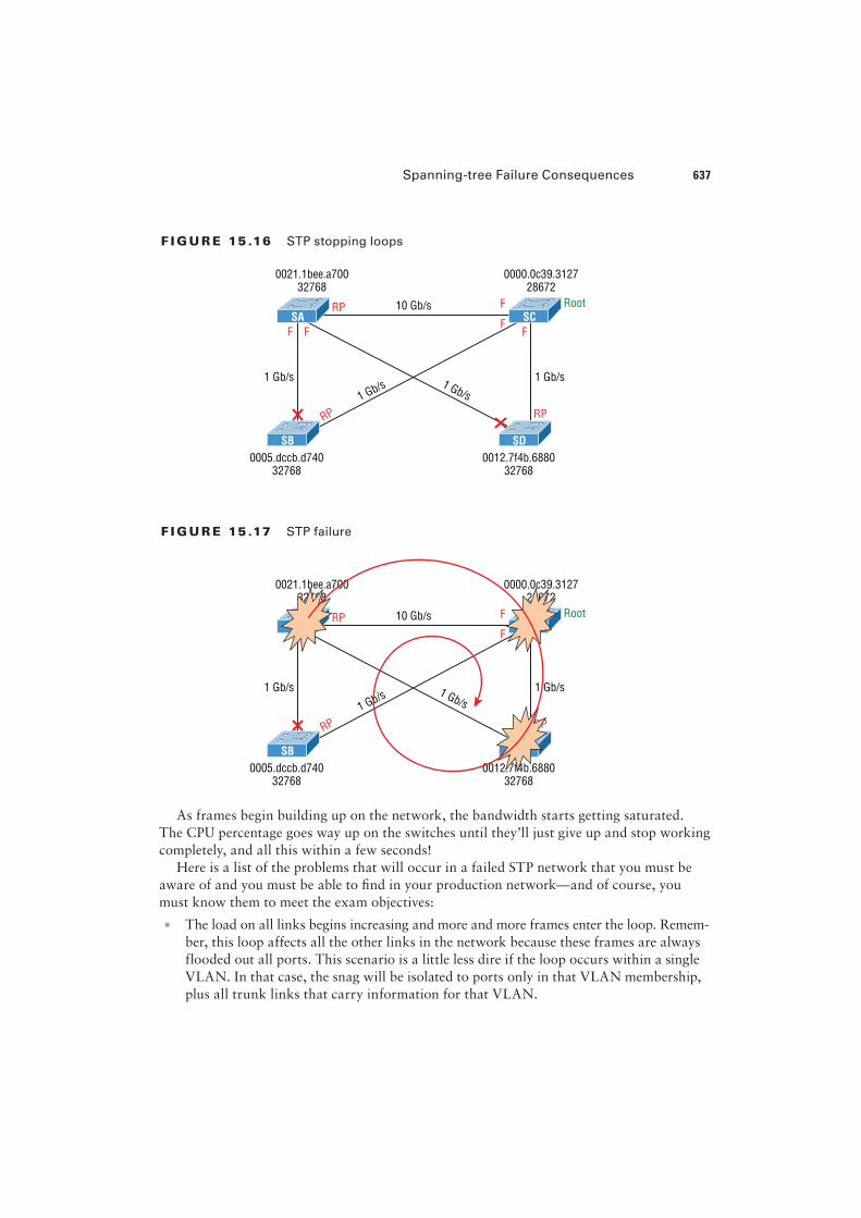
multicast, and unicasts not in the CAM are now in an endless loop. Figure 15.17 shows us
the carnage—when you see all the lights on each port blinking super-fast amber/green, this
means serious errors are occurring, and lots of them!
Spanning-tree Failure Consequences 637
F I GU R E 15 .16 STP stopping loops
SB SD
SA SC
0021.1bee.a700
32768
0000.0c39.3127
28672
0005.dccb.d740
32768
0012.7f4b.6880
32768
RP
RPRP
F
FFFF
1 Gb/s1 Gb/s
10 Gb/s
1 Gb/s 1 Gb/s
Root
F I GU R E 15 .17 STP failure
SB SD
SA SC
0021.1bee.a700
32768
0000.0c39.3127
28672
0005.dccb.d740
32768
0012.7f4b.6880
32768
RP
RPRP
F
F
1 Gb/s1 Gb/s
10 Gb/s
1 Gb/s1 Gb/s
Root
As frames begin building up on the network, the bandwidth starts getting saturated.
The CPU percentage goes way up on the switches until they’ll just give up and stop working
completely, and all this within a few seconds!
Here is a list of the problems that will occur in a failed STP network that you must be
aware of and you must be able to "nd in your production network—and of course, you
must know them to meet the exam objectives:
u The load on all links begins increasing and more and more frames enter the loop. Remem-
ber, this loop affects all the other links in the network because these frames are always
flooded out all ports. This scenario is a little less dire if the loop occurs within a single
VLAN. In that case, the snag will be isolated to ports only in that VLAN membership,
plus all trunk links that carry information for that VLAN.
638 Chapter 15 u Enhanced Switched Technologies
u If you have more than one loop, traffic will increase on the switches because all the
circling frames actually get duplicated. Switches basically receive a frame, make a copy
of it, and send it out all ports. And they do this over and over and over again with the
same frame, as well as for any new ones!
u The MAC address table is now completely unstable. It no longer knows where any
source MAC address hosts are actually located because the same source address comes
in via multiple ports on the switch.
u With the overwhelmingly high load on the links and the CPUs, now possibly at 100%
or close to that, the devices become unresponsive, making it impossible to trouble-
shoot—it’s a terrible thing!
At this point your only option is to systematically remove every redundant link between
switches until you can "nd the source of the problem. And don’t freak because, eventually,
your ravaged network will calm down and come back to life after STP converges. Your
fried switches will regain consciousness, but the network will need some serious therapy, so
you’re not out of the woods yet!
Now is when you start troubleshooting to "nd out what caused the disaster in the "rst
place. A good strategy is to place the redundant links back into your network one at a time
and wait to see when a problem begins to occur. You could have a failing switch port, or
even a dead switch. Once you’ve replaced all your redundant links, you need to carefully
monitor the network and have a back-out plan to quickly isolate the problem if it reoccurs.
You don’t want to go through this again!
You’re probably wondering how to prevent these STP problems from ever darkening
your doorstep in the "rst place. Well, just hang on, because after the next section, I’ll
tell you all about EtherChannel, which can stop ports from being placed in the blocked/
discarding state on redundant links to save the day! But before we add more links to our
switches and then bundle them, let’s talk about PortFast.
PortFast and BPDU Guard
If you have a server or other devices connected into your switch that you’re totally sure
won’t create a switching loop if STP is disabled, you can use a Cisco proprietary extension
to the 802.1d standard called PortFast on these ports. With this tool, the port won’t spend
the usual 50 seconds to come up into forwarding mode while STP is converging, which is
what makes it so cool.
Since ports will transition from blocking to forwarding state immediately, PortFast can
prevent our hosts from being potentially unable to receive a DHCP address due to STP’s
slow convergence. If the host’s DHCP request times out, or if every time you plug a host
in you’re just tired of looking at the switch port being amber for almost a minute before it
transitions to forwarding state and turns green, PortFast can really help you out!
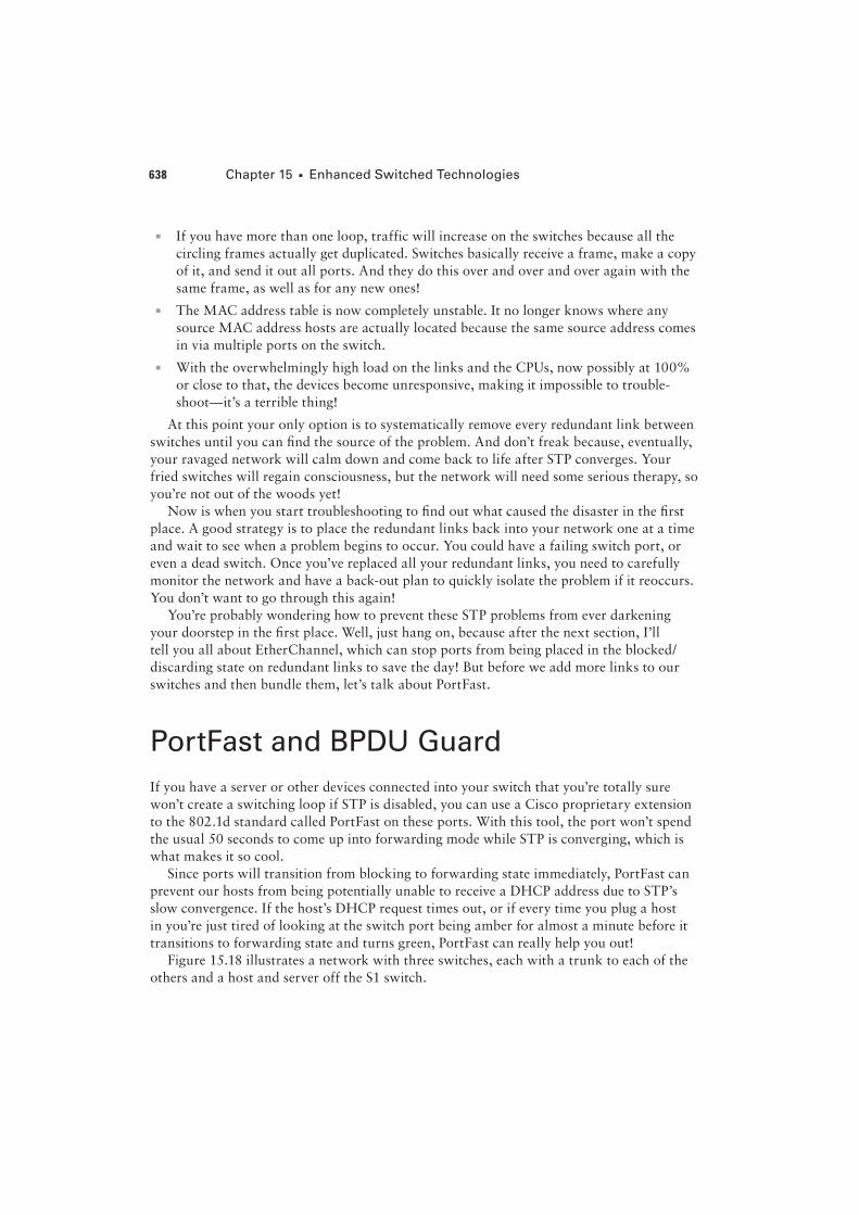
Figure 15.18 illustrates a network with three switches, each with a trunk to each of the
others and a host and server off the S1 switch.
PortFast and BPDU Guard 639
F I GU R E 15 .18 PortFast
Trunk
Trunk Trunk
S1
S3 S2
Gi0/1
Access Access
Gi0/2
We can use PortFast on the ports on S1 to help them transition to the STP forwarding
state immediately upon connecting to the switch.
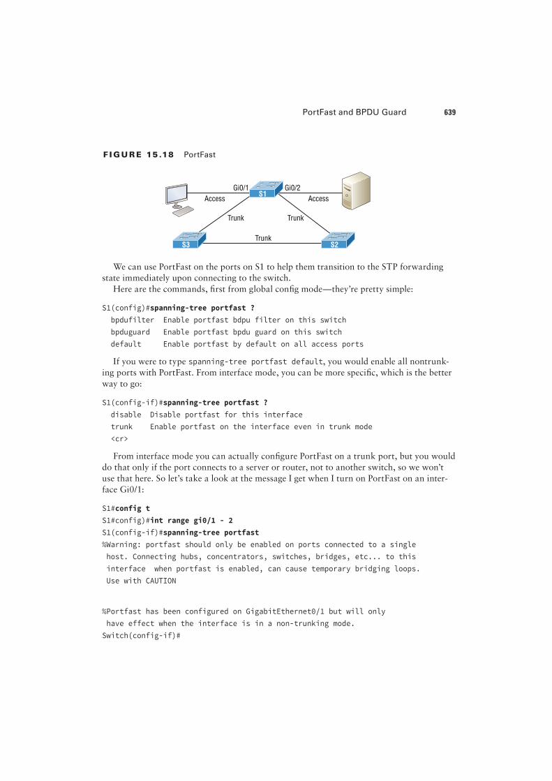
Here are the commands, "rst from global con"g mode—they’re pretty simple:
S1(config)#spanning-tree portfast ?
bpdufilter Enable portfast bdpu filter on this switch
bpduguard Enable portfast bpdu guard on this switch
default Enable portfast by default on all access ports
If you were to type spanning-tree portfast default, you would enable all nontrunk-
ing ports with PortFast. From interface mode, you can be more speci"c, which is the better
way to go:
S1(config-if)#spanning-tree portfast ?
disable Disable portfast for this interface
trunk Enable portfast on the interface even in trunk mode
<cr>
From interface mode you can actually con"gure PortFast on a trunk port, but you would
do that only if the port connects to a server or router, not to another switch, so we won’t
use that here. So let’s take a look at the message I get when I turn on PortFast on an inter-
face Gi0/1:
S1#config t
S1#config)#int range gi0/1 - 2
S1(config-if)#spanning-tree portfast
%Warning: portfast should only be enabled on ports connected to a single
host. Connecting hubs, concentrators, switches, bridges, etc... to this
interface when portfast is enabled, can cause temporary bridging loops.
Use with CAUTION
%Portfast has been configured on GigabitEthernet0/1 but will only
have effect when the interface is in a non-trunking mode.
Switch(config-if)#
640 Chapter 15 u Enhanced Switched Technologies
PortFast is enabled on port Gi0/1 and Gi0/2, but notice that you get a pretty long mes-
sage that’s essentially telling you to be careful. This is because when using PortFast, you
de"nitely don’t want to create a network loop by plugging another switch or hub into a
port that’s also con"gured with PortFast! Why? Because if you let this happen, even though
the network may still sort of work, data will pass super slowly, and worse, it could take you
a really long time to "nd the source of the problem, making you very unpopular. So pro-
ceed with caution!
At this juncture, you would be happy to know that there are some safeguard commands
to have handy when using PortFast just in case someone causes a loop in a port that’s con-
"gured with PortFast enabled. Let’s talk a really key safeguard command now.
BPDU Guard
If you turn on PortFast for a switch port, it’s a really good idea to turn on BPDU Guard
as well. In fact, it’s such a great idea, I personally feel that it should be enabled by default
whenever a port is con"gured with PortFast!
This is because if a switch port that has PortFast enabled receives a BPDU on that port,
it will place the port into error disabled (shutdown) state, effectively preventing anyone
from accidentally connecting another switch or hub port into a switch port con"gured with
PortFast. Basically, you’re preventing (guarding) your network from being severely crippled
or even brought down. So let’s con"gure our S1 interface, which is already con"gured with
PortFast, with BPDU Guard now—it’s easy!
Here’s how to set it globally:
S1(config)# spanning-tree portfast bpduguard default
And speci"cally on an interface:
S1(config-if)#spanning-tree bpduguard enable
It’s important to know that you would only con"gure this command on your access
layer switches—switches where users are directly connected.
Hedging My Bets Created Bad Switch Ports During the Super Bowl
A junior admin called me frantically telling me all switch ports have just gone bad on the
core switch, which was located at the data center where I was lead consultant for a data
center upgrade. Now these things happen, but keep in mind that I just happened to be at
a Super Bowl party having a great time watching my favorite team play in the “Big One”
when I received this call! So I took a deep breath to refocus. I needed to find out some key
information to determine just how bad the situation really was, and my client was in as
big of a hurry as I was to get to a solution!
Visit ccna .gg/ch15/b for a companion MicroNugget from CBT Nuggets.
PortFast and BPDU Guard 641
First I asked the junior admin exactly what he did. Of course, he said, “Nothing, I swear!”
I figured that’s what he’d say, so I pressed him for more info and finally asked for stats on
the switch. The admin told me that all the ports on the 10/100/1000 line card went amber
at the same time—finally some information I could use! I confirmed that, as suspected,
these ports trunked to uplink distribution switches. Okay, wow—this was not good!
At this point, though, I found it hard to believe that all 24 ports would suddenly go bad,
but it’s possible, so I asked if he had a spare card to try. He told me that he had already
put in the new card but the same thing was still happening. Well, okay—it’s not the card,
or the ports, but maybe something happened with the other switches. I knew there were
a lot of switches involved, so someone must have screwed something up to make this
catastrophe happen! Or, maybe the fiber distribution closet went down somehow? If so,
how? Was there a fire in the closet or something? Some serious internal shenanigans
would be the only answer if that were the cause!
So remaining ever-patient (because, to quote Dr. House, “Patients lie”), I again had to ask
the admin exactly what he did, and sure enough, he finally admitted that he tried to plug his
personal laptop into the core switch so he could watch the Super Bowl, and quickly added,
“…but that’s it, I didn’t do anything else!” I’ll skip over the fact that this guy was about to
have the ugliest Monday ever, but something still didn’t make sense, and here’s why.
Knowing that the ports on that card would all connect to distribution switches, I config-
ured the ports with PortFast so they wouldn’t have to transition through the STP process.
And because I wanted to make sure no one plugged a switch into any of those ports, I
enabled BPDU Guard on the entire line card.
But a host would not bring down those ports, so I asked him if he had plugged in the lap-
top directly or used something in between. He admitted that he had indeed used another
switch because, turns out, there were lots of people from the office who wanted to plug
into the core switch and watch the game too. Was he kidding me? The security policy
wouldn’t allow connecting from their offices, so wouldn’t you think they’d consider the
core even more off-limits? Some people!
But wait… This doesn’t explain all ports turning amber, because only the one he plugged
into should be doing that. It took me a second, but I figured out what he did and finally
got him to confess. When he plugged the switch in, the port turned amber so he thought
it went bad. So what do think he did? Well, if at first you don’t succeed, try, try again, and
that’s just what he did—he actually kept trying ports—all 24 of them to be exact! Now
that’s what I call determined!
Sad to say, I got back to the party in time just to watch my team lose in the last few min-
utes! A dark day, indeed!
642 Chapter 15 u Enhanced Switched Technologies
EtherChannel
Know that almost all Ethernet networks today will typically have multiple links between
switches because this kind of design provides redundancy and resiliency. On a physical
design that includes multiple links between switches, STP will do its job and put a port
or ports into blocking mode. In addition to that, routing protocols like OSPF and EIGRP
could see all these redundant links as individual ones, depending on the con"guration,
which can mean an increase in routing overhead.
We can gain the bene"ts from multiple links between switches by using port channel-
ing. EtherChannel is a port channel technology that was originally developed by Cisco as
a switch-to-switch technique for grouping several Fast Ethernet or Gigabit Ethernet ports
into one logical channel.
Also important to note is that once your port channel (EtherXhannel) is up and work-
ing, layer 2 STP and layer 3 routing protocols will treat those bundled links as a single one,
which would stop STP from performing blocking. An additional nice result is that because
the routing protocols now only see this as a single link, a single adjacency across the link
can be formed—elegant!
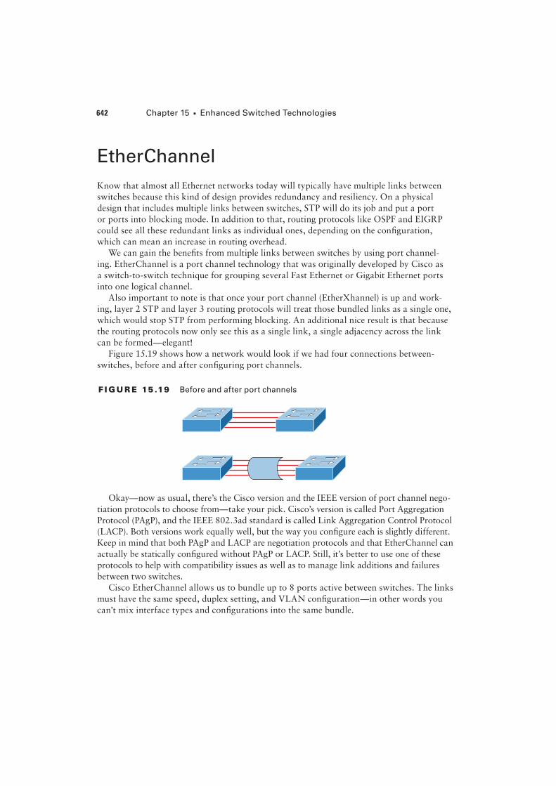
Figure 15.19 shows how a network would look if we had four connections between-
switches, before and after con"guring port channels.
F I GU R E 15 .19 Before and after port channels
Okay—now as usual, there’s the Cisco version and the IEEE version of port channel nego-
tiation protocols to choose from—take your pick. Cisco’s version is called Port Aggregation
Protocol (PAgP), and the IEEE 802.3ad standard is called Link Aggregation Control Protocol
(LACP). Both versions work equally well, but the way you con"gure each is slightly different.
Keep in mind that both PAgP and LACP are negotiation protocols and that EtherChannel can
actually be statically con"gured without PAgP or LACP. Still, it’s better to use one of these
protocols to help with compatibility issues as well as to manage link additions and failures
between two switches.
Cisco EtherChannel allows us to bundle up to 8 ports active between switches. The links
must have the same speed, duplex setting, and VLAN con"guration—in other words you
can’t mix interface types and con"gurations into the same bundle.
EtherChannel 643
There are a few differences in con"guring PAgP and LACP, but "rst, let’s go over some
terms so you don’t get confused:
Port channeling Refers to combining two-to-eight Fast Ethernet or two-Gigabit Ethernet
ports together between two switches into one aggregated logical link to achieve more band-
width and resiliency.
EtherChannel Cisco’s proprietary term for port channeling.
PAgP This is a Cisco proprietary port channel negotiation protocol that aids in the auto-
matic creation for EtherChannel links. All links in the bundle must match the same
parameters (speed, duplex, VLAN info), and when PAgP identi"es matched links, it
groups the links into an EtherChannel. This is then added to STP as a single bridge port.
At this point, PAgP’s job is to send packets every 30 seconds to manage the link for consis-
tency, any link additions, and failures.
LACP (802.3ad) This has the exact same purpose as PAgP, but is nonproprietary so it can
work between multi-vendor networks.
Channel-group This is a command on Ethernet interfaces used to add the speci"ed inter-
face to a single EtherChannel. The number following this command is the port channel ID.
Interface port-channel Here’s a command that creates the bundled interface. Ports can
be added to this interface with the channel-group command. Keep in mind that the inter-
face number must match the group number.
Okay, now let’s see if you can make some sense out of all these terms by actually con"g-
uring something!
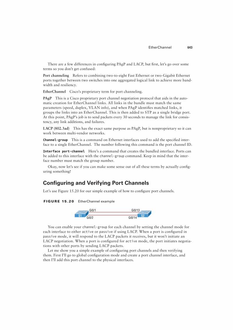
Configuring and Verifying Port Channels
Let’s use Figure 15.20 for our simple example of how to con"gure port channels.
F I GU R E 15 . 20 EtherChannel example
Gi0/1 Gi0/13
Gi0/2 Gi0/14S1 S2
You can enable your channel-group for each channel by setting the channel mode for
each interface to either active or passive if using LACP. When a port is con"gured in
passive mode, it will respond to the LACP packets it receives, but it won’t initiate an
LACP negotiation. When a port is con"gured for active mode, the port initiates negotia-
tions with other ports by sending LACP packets.
Let me show you a simple example of con"guring port channels and then verifying
them. First I’ll go to global con"guration mode and create a port channel interface, and
then I’ll add this port channel to the physical interfaces.
644 Chapter 15 u Enhanced Switched Technologies
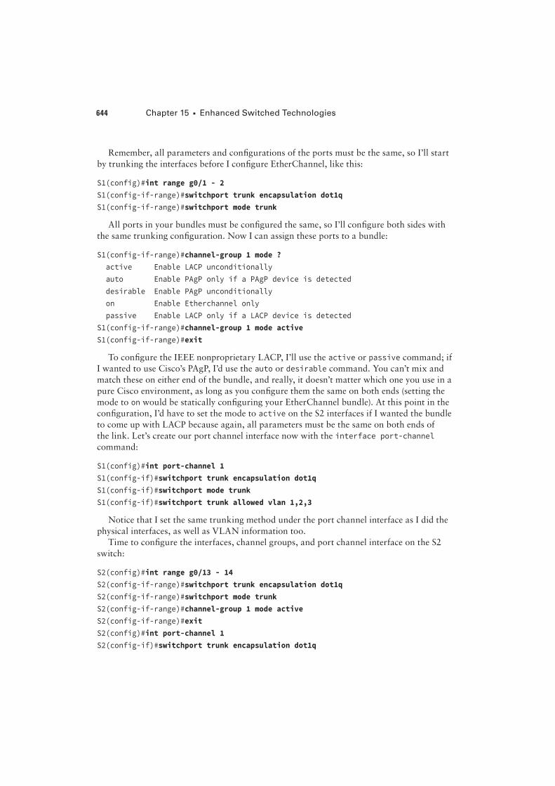
Remember, all parameters and con"gurations of the ports must be the same, so I’ll start
by trunking the interfaces before I con"gure EtherChannel, like this:
S1(config)#int range g0/1 - 2
S1(config-if-range)#switchport trunk encapsulation dot1q
S1(config-if-range)#switchport mode trunk
All ports in your bundles must be con"gured the same, so I’ll con"gure both sides with
the same trunking con"guration. Now I can assign these ports to a bundle:
S1(config-if-range)#channel-group 1 mode ?
active Enable LACP unconditionally
auto Enable PAgP only if a PAgP device is detected
desirable Enable PAgP unconditionally
on Enable Etherchannel only
passive Enable LACP only if a LACP device is detected
S1(config-if-range)#channel-group 1 mode active
S1(config-if-range)#exit
To con"gure the IEEE nonproprietary LACP, I’ll use the active or passive command; if
I wanted to use Cisco’s PAgP, I’d use the auto or desirable command. You can’t mix and
match these on either end of the bundle, and really, it doesn’t matter which one you use in a
pure Cisco environment, as long as you con"gure them the same on both ends (setting the
mode to on would be statically con"guring your EtherChannel bundle). At this point in the
con"guration, I’d have to set the mode to active on the S2 interfaces if I wanted the bundle
to come up with LACP because again, all parameters must be the same on both ends of
the link. Let’s create our port channel interface now with the interface port-channel
command:
S1(config)#int port-channel 1
S1(config-if)#switchport trunk encapsulation dot1q
S1(config-if)#switchport mode trunk
S1(config-if)#switchport trunk allowed vlan 1,2,3
Notice that I set the same trunking method under the port channel interface as I did the
physical interfaces, as well as VLAN information too.
Time to con"gure the interfaces, channel groups, and port channel interface on the S2
switch:
S2(config)#int range g0/13 - 14
S2(config-if-range)#switchport trunk encapsulation dot1q
S2(config-if-range)#switchport mode trunk
S2(config-if-range)#channel-group 1 mode active
S2(config-if-range)#exit
S2(config)#int port-channel 1
S2(config-if)#switchport trunk encapsulation dot1q
EtherChannel 645
S2(config-if)#switchport mode trunk
S2(config-if)#switchport trunk allowed vlan 1,2,3
On each switch, I con"gured the ports I wanted to bundle with the same con"guration,
then created the port channel. After that, I added the ports into the port channel with the
channel-group command.
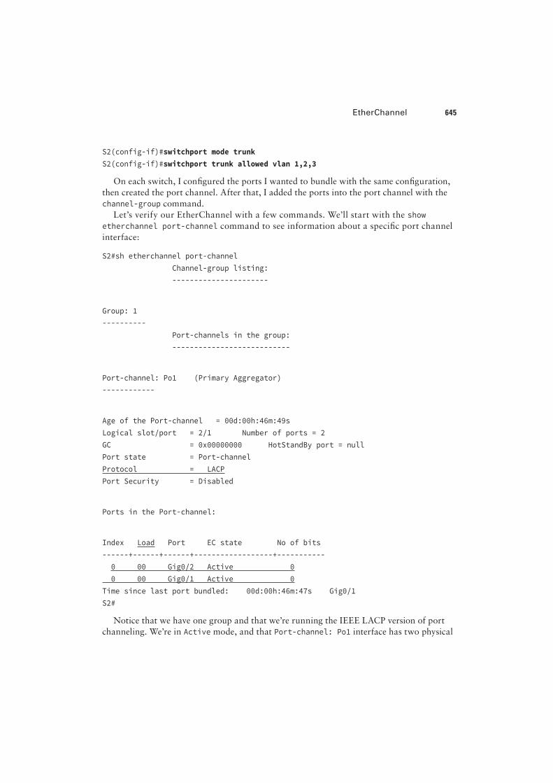
Let’s verify our EtherChannel with a few commands. We’ll start with the show
etherchannel port-channel command to see information about a speci"c port channel
interface:
S2#sh etherchannel port-channel
Channel-group listing:
----------------------
Group: 1
----------
Port-channels in the group:
---------------------------
Port-channel: Po1 (Primary Aggregator)
------------
Age of the Port-channel = 00d:00h:46m:49s
Logical slot/port = 2/1 Number of ports = 2
GC = 0x00000000 HotStandBy port = null
Port state = Port-channel
Protocol = LACP
Port Security = Disabled
Ports in the Port-channel:
Index Load Port EC state No of bits
------+------+------+------------------+-----------
0 00 Gig0/2 Active 0
0 00 Gig0/1 Active 0
Time since last port bundled: 00d:00h:46m:47s Gig0/1
S2#
Notice that we have one group and that we’re running the IEEE LACP version of port
channeling. We’re in Active mode, and that Port-channel: Po1 interface has two physical
646 Chapter 15 u Enhanced Switched Technologies
interfaces. The heading Load is not the load over the interfaces, it’s a hexadecimal value
that decides which interface will be chosen to specify the "ow of traf!c.
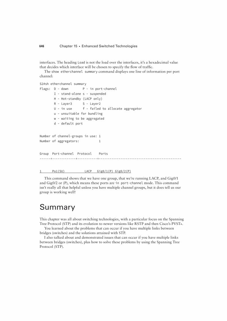
The show etherchannel summary command displays one line of information per port
channel:
S2#sh etherchannel summary
Flags: D - down P - in port-channel
I - stand-alone s - suspended
H - Hot-standby (LACP only)
R - Layer3 S - Layer2
U - in use f - failed to allocate aggregator
u - unsuitable for bundling
w - waiting to be aggregated
d - default port
Number of channel-groups in use: 1
Number of aggregators: 1
Group Port-channel Protocol Ports
------+-------------+-----------+----------------------------------------------
1 Po1(SU) LACP Gig0/1(P) Gig0/2(P)
This command shows that we have one group, that we’re running LACP, and Gig0/1
and Gig0/2 or (P), which means these ports are in port-channel mode. This command
isn’t really all that helpful unless you have multiple channel groups, but it does tell us our
group is working well!
Summary
This chapter was all about switching technologies, with a particular focus on the Spanning
Tree Protocol (STP) and its evolution to newer versions like RSTP and then Cisco’s PVST+.
You learned about the problems that can occur if you have multiple links between
bridges (switches) and the solutions attained with STP.
I also talked about and demonstrated issues that can occur if you have multiple links
between bridges (switches), plus how to solve these problems by using the Spanning Tree
Protocol (STP).