![Inverse Kinematics and Gaze Stabilization for the Rochester ......3 Inverse Kinematics 3.1 Inverse Kinematics: O,A,T from TOOL The mathematics in [Brown and Rimey, 1988] Section 9](https://static.fdocuments.in/doc/165x107/60be15e583990e1ab8600327/inverse-kinematics-and-gaze-stabilization-for-the-rochester-3-inverse-kinematics.jpg)
Ch. 7: Dynamics. Example: three link cylindrical robot Up to this point, we have developed a...
23
Ch. 7: Dynamics
-
date post
20-Dec-2015 -
Category
Documents
-
view
214 -
download
0
Transcript of Ch. 7: Dynamics. Example: three link cylindrical robot Up to this point, we have developed a...

Ch. 7: Dynamics

Example: three link cylindrical robot
• Up to this point, we have developed a systematic method to determine the forward and inverse kinematics and the Jacobian for any arbitrary serial manipulator– Forward kinematics: mapping from joint
variables to position and orientation of the end effector
– Inverse kinematics: finding joint variables that satisfy a given position and orientation of the end effector
– Jacobian: mapping from the joint velocities to the end effector linear and angular velocities
• Example: three link cylindrical robot

Why are we studying inertial dynamics and control?
Kinematic vs dynamic models:
• What we’re really doing is modeling the manipulator
• Kinematic models
• Simple control schemes
• Good approximation for manipulators at low velocities and accelerations when inertial coupling between links is small
• Not so good at higher velocities or accelerations
• Dynamic models
• More complex controllers
• More accurate

Methods to Analyze Dynamics
• Two methods:– Energy of the system: Euler-Lagrange method
– Iterative Link analysis: Euler-Newton method
• Each has its own ads and disads. • In general, they are the same and the results are the same.

Terminology
• Definitions– Generalized coordinates:
– Vector norm: measure of the magnitude of a vector• 2-norm:
– Inner product:

Euler-Lagrange Equations
• We can derive the equations of motion for any nDOF system by using energy methods

Ex: 1DOF system
• To illustrate, we derive the equations of motion for a 1DOF system– Consider a particle of mass m
– Using Newton’s second law:
Euler-Lagrange Equations
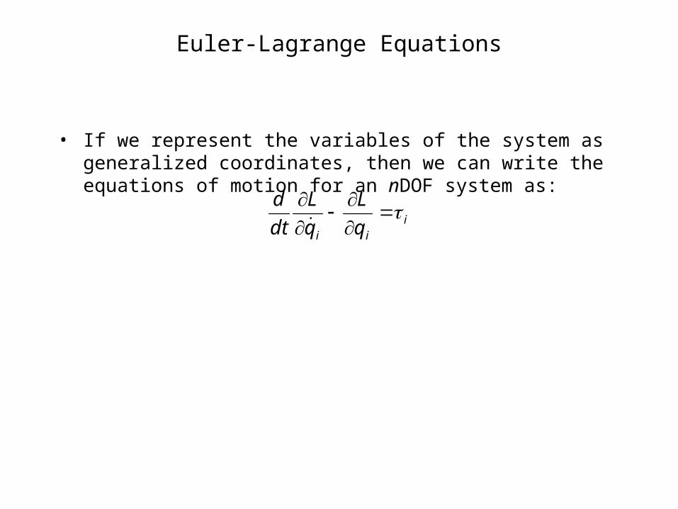
• If we represent the variables of the system as generalized coordinates, then we can write the equations of motion for an nDOF system as:
iii q
L
q
L
dt
d

Ex: 1DOF system

Ex: 1DOF system
• Let the total inertia, J, be defined by:
• :lm JJrJ 2

Inertia
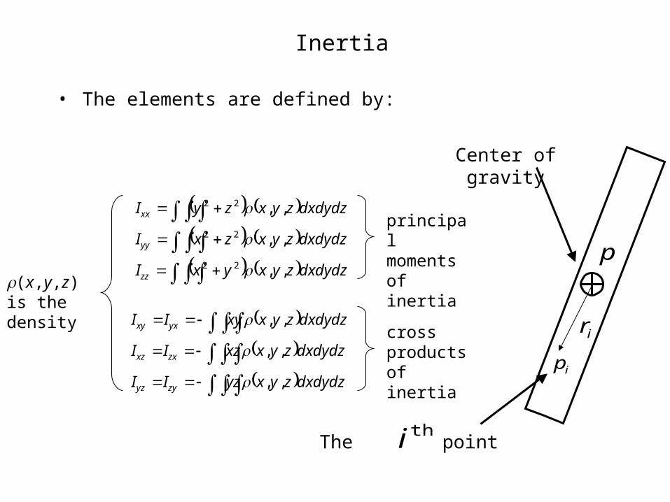
• Inertia, in the body attached frame, is an intrinsic property of a rigid body– In the body frame, it is a constant 3x3 matrix:
– The diagonal elements are called the principal moments of inertia and are a representation of the mass distribution of a body with respect to an axis of rotation:
• r is the distance from the axis of rotation to the particle
zzzyzx
yzyyyx
xzxyxx
ij
III
III
III
II
VVV
ii dxdydzzyxrdVzyxrdmrI ,,,, 222
Inertia
• The elements are defined by:
dxdydzzyxyxI
dxdydzzyxzxI
dxdydzzyxzyI
zz
yy
xx
,,
,,
,,
22
22
22
dxdydzzyxyzII
dxdydzzyxxzII
dxdydzzyxxyII
zyyz
zxxz
yxxy
,,
,,
,,
(x,y,z) is the density
principal moments of inertia
cross products of inertia ip
ir
p
Center of gravity
The pointthi

The Inertia Matrix
Calculate the moment of inertia of a cuboid about its centroid:
Since the object is symmetrical about the CG, all cross products of inertia are zero
h
dw
x
y
z
Inertia
• First, we need to express the inertia in the body-attached frame– Note that the rotation between the inertial frame and the body
attached frame is just R
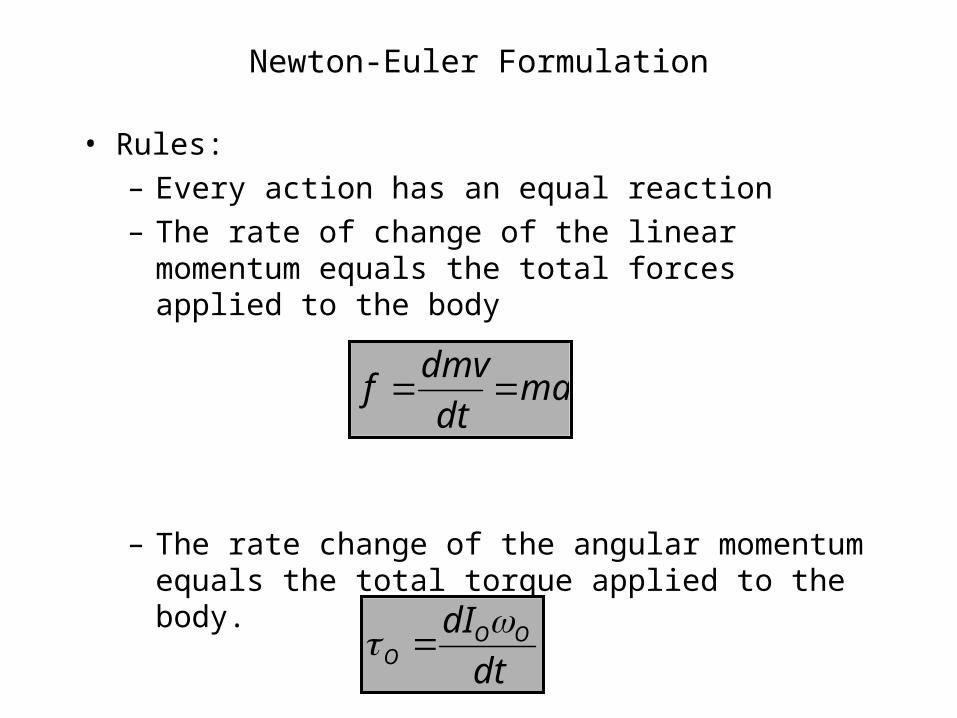
Newton-Euler Formulation
• Rules:– Every action has an equal reaction– The rate of change of the linear momentum equals
the total forces applied to the body
– The rate change of the angular momentum equals the total torque applied to the body.
madt
dmvf
dt
dI OOO
Newton-Euler Formulation
• Euler equation

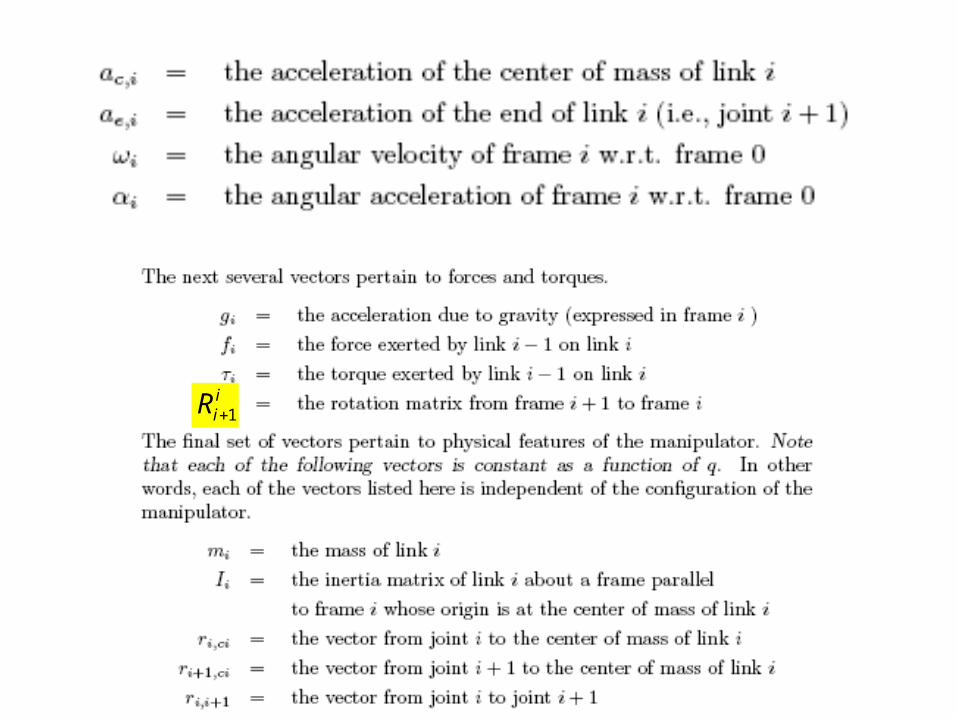
iiR 1

Force and Torque Equilibrium
• Force equilibrium
• Torque equilibrium
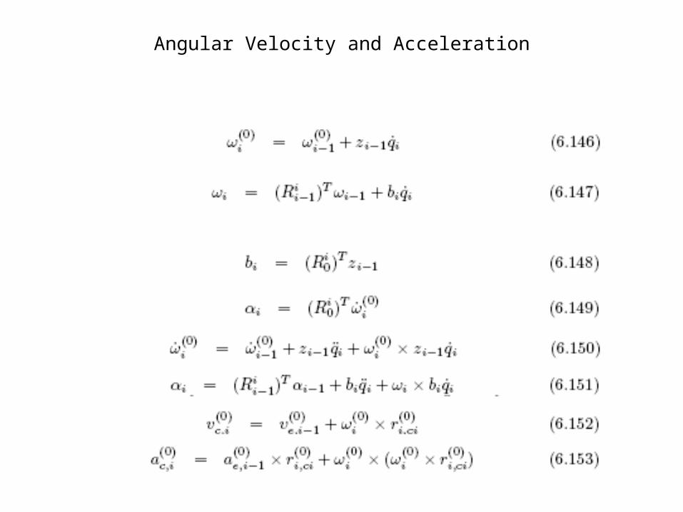
Angular Velocity and Acceleration

Initial and terminal conditions

Next class…
• Moment of Inertia
L1
L2
F

L1
L2
F
FJ T
)21cos(2)21cos(21cos1
)21sin(2))21sin(21sin1(
LLL
LLLJ
)21cos(2)21sin(2
)21cos(21cos1))21sin(21sin1(
LL
LLLLJ T
)2sin(21)det( LLJ T
2
1
f
fF
1tan12 ff