Mathematical Methods for Physicist selected solutions ch 6 & 7

DEPARTMENT : EE SEMESTER :
SUBJECT NAME: Control System Theory
SUBJECT CODE : 3130905
FACULTY NAME :KSHATRIYA KRISHNA
CH 1 :- Introduction to Control Systems (CH 1 and 11 of Techmax)
(1) Give one example of an open loop stable system and open loop unstable system. Explainabout stability of the system. (DEC 2012; 7 Marks)
(2) Write two brief short notes on open loop control systems and closed loop control systemswith the help of neat block diagrams. Explain role of each of the blocks. Give somesuitable real life examples of both types of systems. Discuss their advantages anddisadvantages (May 2012, June 2010; 7 Marks)
(3) Explain the difference between Open loop and Close loop control system with examples.Compare their merits and demerits. (Nov 2011,Dec 2010; 7 Marks)
(4) Derive the transfer function for armature controlled DC motor. (Dec 2013,June 2013,Dec 2010; 7 Marks)
CH 2 :- Mathematical Modeling of Dynamic Systems (CH 2,3,4, and 13 ofTechmax)
(1) For a RLC circuit, derive the state model of the system. (Dec 2010,4 Marks)
(2) Draw the equivalent mechanical system for the given system as per figure.Hence write a set of equilibrium equations and obtain electrical analogouscircuit using (1) F-I analogy (2) F-V analogy. (June 2013, 7 Marks)

DEPARTMENT : EE SEMESTER :
SUBJECT NAME: Control System Theory
SUBJECT CODE : 3130905
FACULTY NAME :KSHATRIYA KRISHNA
(3) Obtain the transfer function X2(s)/U(s) of the mechanical system shown in figure.(Nov 2011,7 Marks)
(4) Write a note on gear train. (Nov 2011,7 Marks)
(5) Find the transfer function of the given network (Nov 2011,7 Marks)

DEPARTMENT : EE SEMESTER :
SUBJECT NAME: Control System Theory
SUBJECT CODE : 3130905
FACULTY NAME :KSHATRIYA KRISHNA
(6) Explain the concept of linearity and time invariance in the context of control systems.Give definition of transfer function and explain the same. (May 2012,7 Marks)
(7) Obtain mathematical model for one mechanical system and one electrical system. Obtaintheir transfer functions . (Dec 2012, 7 Marks)
(8) Explain with suitable example, one method for linearization of nonlinear mathematicalmodel. (Dec 2012, 7 Marks)
(9) A servo system is represented by the signal flow graph shown in fig.3, the variable T isTorque and E as error. Determine The overall transfer function if K1 = 1, K2 =2 and K3= 5. (Dec 2010, 7 Marks)
(10) What is analogous system? Explain Force-Voltage and Force-Current AnalogyWith suitable Example (June 2011,Dec 2010, June 2013 ;7 Marks)
(11) Find Transfer Function of given network in Figure-3. (June 2011,7 Marks)

DEPARTMENT : EE SEMESTER :
SUBJECT NAME: Control System Theory
SUBJECT CODE : 3130905
FACULTY NAME :KSHATRIYA KRISHNA
(12) Using the block diagram reduction techniques, evaluate the closed loop transferfunction of the system as per block diagram given in Figure (Dec 2013, 7 Marks)
(13) Determine close loop transfer function of the system shown below using block diagramreduction techniques. (June 2013, 7 Marks)

DEPARTMENT : EE SEMESTER :
SUBJECT NAME: Control System Theory
SUBJECT CODE : 3130905
FACULTY NAME :KSHATRIYA KRISHNA
(14) Using the block diagram reduction techniques, find the closed loop transfer function of thesystem whose block diagram is given in Fig. (May 2012,7 Marks)
(15) Using block diagram reduction technique find the closed loop transfer function of thesystem whose block diagram is given in figure below. (Nov 2011,7 Marks)
(16) System 1 has transfer Function G1(s) =30 / 4S2+3 S+6 and system 2 has transfer FunctionG2(s) =2 / S+4 .Find cascade and parallel transfer Function for system 1 and system 2. WriteMATLAB program to find cascade, and parallel transfer Function from given transferFunction. (June 2011,7 Marks)
(17) Derive the closed loop transfer function using block diagram reduction technique for the fig.(Dec 2010,7 Marks)

DEPARTMENT : EE SEMESTER :
SUBJECT NAME: Control System Theory
SUBJECT CODE : 3130905
FACULTY NAME :KSHATRIYA KRISHNA
(18) Using the block diagram reduction techniques, find the closed loop transfer function of thesystem whose block diagram is given in Fig. (June 2010,8 Marks)
(19) Find-out transfer function for Signal flow diagram as shown in Figure-1, usingMason’s gains Formula. (Dec 2013,7 Marks)

DEPARTMENT : EE SEMESTER :
SUBJECT NAME: Control System Theory
SUBJECT CODE : 3130905
FACULTY NAME :KSHATRIYA KRISHNA
(20) Determine the transfer function of the system with signal flow graph shown below.(June 2013, 7 Marks)
(21) Explain about signal flow graph using suitable example (Dec 2012, 7 Marks)
(22) Draw signal flow graph of the system, whose block diagram is shown in Fig.1. Obtainclosed loop transfer function of the system using Mason’s gain formula. (May 2012,7 Marks)

DEPARTMENT : EE SEMESTER :
SUBJECT NAME: Control System Theory
SUBJECT CODE : 3130905
FACULTY NAME :KSHATRIYA KRISHNA
(23) Obtain the overall transfer function C/R of the system whose signal flow graph shown infigure below (Nov 2011, 7 Marks)
(24) From block diagram shown in Figure-2, Draw the corresponding signal flow graph andevaluate closed-loop transfer Function using Mason’s gain Formula. (June 2011, 7 Marks)
(25) Find the transfer function for the fig.2 using signal flow graphs. (Dec 2010, 7 Marks)

DEPARTMENT : EE SEMESTER :
SUBJECT NAME: Control System Theory
SUBJECT CODE : 3130905
FACULTY NAME :KSHATRIYA KRISHNA
(26) Draw signal flow graph of the system shown in Fig.1. Obtain overall system transferfunction using Mason’s gain formula. (June 2010;7 Marks)
(27) Explain the advantages of state space approach over classical methods and obtain statevariable equation
Also draw the block diagram. (Dec 2013,June 2010; 7 Marks)
(28) Explain about state space modeling and obtain state space variable model for dc motor(Dec 2012,7 Marks)
(29) Write definitions of state and state variables. Explain the fact that for any system, the set of

DEPARTMENT : EE SEMESTER :
SUBJECT NAME: Control System Theory
SUBJECT CODE : 3130905
FACULTY NAME :KSHATRIYA KRISHNA
state variables are non-unique. Discuss the limitations of transfer functions and advantagesof analysis of control systems using state space. (May 2012, 7 Marks)
(30) Write state equation and output equation for a generalized control system using matrices A,B, C and D. Write two different state equations for a mass-spring and damper system. Findeigenvalues of system matrix A in both cases. Comment on your result. Assume suitablesymbols for constants of all three elements. (May 2012, 7 Marks)
(31) Obtain state space representation of system shown in Figure-1 (June 2011, 7 Marks)
(32) Describe Correlation between transfer function and state-space equations with suitableexamples (June 2011, 7 Marks)
(33) Obtain the transfer function of the system defined by following state-space equations.(June 2010,8 Marks)
CH 3:- Mathematical Modeling of Fluid Systems and Thermal systems (CH 12Of Techmax)
(1) Explain Liquid Level system and Derive Transfer Function of Liquid Level system withInteraction. (Dec 2013,Dec 2012,June 2011 7 Marks)
(2) Explain about thermal system giving suitable example and obtain its transfer function.(Dec 2012,May 2012,June 2010; 7 Marks)
(3) Give the names of the analogous quantities in thermal and liquid level systems analogous tocharge, current, voltage and resistance in electrical systems? (Nov 2011, 4 Marks)

DEPARTMENT : EE SEMESTER :
SUBJECT NAME: Control System Theory
SUBJECT CODE : 3130905
FACULTY NAME :KSHATRIYA KRISHNA
CH 4 :- Transient and Steady state Response Analysis (CH 5,6,14 OfTechmax)
(1) Close loop transfer function of control system is given by
(a) Determine the range of K must be lie for the system to be stable.(b) What should be upper limit of K is all the close loop pole are required to be the left side of
the line (σ = -1). (June 2013, 7 Marks)
(2) Derive expression of response, c(t), of second order unity feedback system whose closed-loop transfer function is given below, for a unit step input as a function of time t anddamping ratio ζ. Derive expression of c(t) for ζ=0 and ζ=1
Also Derive expressions of (i) Rise time, tr (ii) Peak time, tp and (iii) Peak overshoot, Mp forthe system (June 2013,June 2010; 14 Marks)
(3) A second order control system is subjected to unit step input. Draw response curves forunderdamped, overdamped and critically damped system. For underdamped system definevarious performance indices. (June 2013, 7 Marks)
(4) Consider the system as shown in figure. Determine the value of ‘a’ such that the dampingratio is 0.5. Also obtain the values of rise time and maximum overshoot Mp in its stepresponse. (June 2013, 7 Marks)

DEPARTMENT : EE SEMESTER :
SUBJECT NAME: Control System Theory
SUBJECT CODE : 3130905
FACULTY NAME :KSHATRIYA KRISHNA
(5) Determine the value of ‘K’ and ‘a’ such that the system has a damping ratio of 0.7 and anundamped natural frequency of 4 rad/sec for the system shown below.(June 2013, 7 Marks)
(6) Write note on steady state error and error constants (June 2013, 7 Marks)
(7) Explain about time constant of first and second order control system . (Dec 2012, 7 Marks)
(8) Find out the output response c(t) of the transfer function shown below for the step input.
Plot the step response on the graph paper (Dec 2012, 7 Marks)
(9) For the second order system with transfer function as given below, obtain Maximumpercentage overshoot M
pand peak time T
p. (Dec 2012, 7 Marks)

DEPARTMENT : EE SEMESTER :
SUBJECT NAME: Control System Theory
SUBJECT CODE : 3130905
FACULTY NAME :KSHATRIYA KRISHNA
(10) For a unity feedback control systems shown below, obtain steady state error for step input
(Dec 2012, 7 Marks)
(11) For the unity feedback control system with
Find the range of K for system that will cause the system to be stable, marginally stable andunstable. Make suitable comments. (Dec 2012, 7 Marks)
(12) Draw sketches of three time responses of a second order system for a unit step input forunder damped, critically damped and over damped systems. Give definitions of fiveperformance indices with the help of sketch drawn for underdamped system.(May 2012, 7 Marks)
(13)The open loop transfer function of a unity feed back system is given by
where k and T are constants. By what factor should the amplifier gain be reduced so that thepeak overshoot of the system is reduced from 75% to 25% ? (Nov 2011, 5 Marks)
(14) A unity feed back system is characterized by open loop transfer function
Determine gain k so that the system will have a damping ratio of 0.5. (Nov 2011, 5 Marks)

DEPARTMENT : EE SEMESTER :
SUBJECT NAME: Control System Theory
SUBJECT CODE : 3130905
FACULTY NAME :KSHATRIYA KRISHNA
(15) A system has following transfer Function C(s) /R(s) =20 / S+10. Determine its unit impulse,step and ramp response with zero initial conditions. Sketch the response.(June 2011, 7 Marks)
(16) Explain Standard Test signals. Explain types of the system and steady state error constantsfor the same (June 2011,Dec 2010,June 2013; 7 Marks)
(17) Explain with example the first order system. (Dec 2010, 4 Marks)
(18) Explain with necessary equation and diagram, second order step response of the system.(Dec 2010, 7 Marks)
(19) Consider the first order system with a controller as shown in Fig. 2.(i) Find the steady state error ess with unit step input using a proportional controller with
gain Kp. (see Fig. 2a)(ii) Find the steady state error ess with unit step input using an integral controller gain Ki.
Comment on the results. (see Fig. 2b) (June 2010, 7 Marks)
(20) Using Routh’s criterion check the stability of a system whose characteristic equation isgiven by
(June 2013, 7 Marks)
(21) Using Routh array Determine the range of K for a unity feedback system whose open loopt.f. is given by
(June 2013, 7 Marks)

DEPARTMENT : EE SEMESTER :
SUBJECT NAME: Control System Theory
SUBJECT CODE : 3130905
FACULTY NAME :KSHATRIYA KRISHNA
(22) For the unity feedback control system with
Determine the range of K for stability using R-H criteria (June 2013, 7 Marks)
(23) Write two notions of stability and a brief note on stability of control systems. Draw sketchesof impulse response of control system having different locations of poles to explain theconcept of stability.(May 2012, 7 Marks)
(24) Determine the stability of the systems represented by the characteristic equation s6 + 3s5 +5s4 + 9s3 + 8s2 + 6s + 4 = 0 by means of the Routh criterion. Determine the number of rootsof the characteristic equation lying in the right half of s-plane. (Nov 2011, 7 Marks)
(25) The characteristic equation of the system is given by s4 + 2s3 + (4 + k) s2 + 9s + 25 = 0.Determine the range of k for the system to be stable. (Nov 2011, 5 Marks)
(26) The characteristic equation of Feedback control system is S4+20S3+15S2+2S+K=0 .(a) Determine range of K for system stability.(b) Can the system be marginally stable ? If so, find the required value of K and
Frequency of sustained oscillations. (June 2011, 7 Marks)
(27) By means of Routh criterion, determine the stability of the system described bycharacteristic equation,S4 + 2S3 + 8S2 + 4S + 3 = 0 (Dec 2010, 4 Marks)
(28) By means of Routh criterion, determine the range of K for stability of the system describedby characteristic equation, S3 + 8S2 + 2S + 4K = 0 (Dec 2010,4 Marks)
(29) Find the number of roots in the right half of the s-plane using R-H criterion, for thecharacteristic equation given below: (Dec 2010, 7 Marks)
(30) Consider a sixth-order system with the characteristic equation given below. Using R-Hcriterion, comment on its stability and find the roots on imaginary axis if any.

DEPARTMENT : EE SEMESTER :
SUBJECT NAME: Control System Theory
SUBJECT CODE : 3130905
FACULTY NAME :KSHATRIYA KRISHNA
(June 2010, 7 Marks)
(31) Describe effects of integral and derivative controls on the performance of control systems.Discuss steady state error constants. (May 2012, 7 Marks)
(32) Explain two position ON-OFF control action with example (Dec 2010, 7 Marks)
(33) Explain about integral action and derivative action on system performance. Can integralaction be used alone ? (Dec 2012 , 7 Marks)
CH 5 :- Root Locus Analysis (CH 7 Of Techmax)
(1) Explain the various rules for construction of root locus. (Dec 2013,June 2011; 7 Marks)
(2) Draw the approximate root-locus diagram for close loop system whose transfer function isgiven by
(Dec 2013, 7 Marks)
(3) The open loop transfer function of a feedback control system is given by
Draw complete root locus plot as K varies from 0 to ∞. Also calculate the value of K forwhich the system becomes oscillatory. (june 2013,june 2011; 14 Marks)
(4) Obtain root-locus plot for the unity feedback system with transfer function.

DEPARTMENT : EE SEMESTER :
SUBJECT NAME: Control System Theory
SUBJECT CODE : 3130905
FACULTY NAME :KSHATRIYA KRISHNA
(Dec 2012, 7 Marks)
(5) Sketch the root loci of unity feedback control system on a graph paper using a suitable scale,whose open-loop transfer function is given below. Determine the range of gain for stabilityand the point at which it crosses the imaginary axis. Determine the value of gain K at thebreakaway point.
(May 2012, 7 Marks)
(6) Explain how (i) Breakaway points (ii) the point at which root locus crosses imaginary axisand (iii) response of closed loop system at a given value of gain are found for a root locus ofgiven system. Explain how at a given point on the root locus, the gain can be determined.
(May 2012, 7 Marks)(7) (i) State whether the root locus tool is a frequency response or a time response tool.
(ii) Compare root locus technique and Bode plots for control system analysis purpose.Explain how root locus technique is more difficult than the Bode plots.
(iii) Explain the frequency response, state its applications with possible limitations
(May 2012, 7 Marks)
(8) A unity Feedback system has open loop Transfer Function,
Obtain its root locus (June 2011, 14 Marks)
(10) Plot the root locus for given transfer function. G(s) = K/s(s+1)(s+4).Find the value of gain k at S = -1±2j. (Dec 2010, 7 Marks)
(11) Sketch the root loci of unity feedback control system on a graph paper using a suitable scale,

DEPARTMENT : EE SEMESTER :
SUBJECT NAME: Control System Theory
SUBJECT CODE : 3130905
FACULTY NAME :KSHATRIYA KRISHNA
whose open-loop transfer function is given below. Determine the range of gain for stabilityand the point at which it crosses the imaginary axis. Determine the value of gain K at thebreakaway point. (June 2010, 7 Marks)
CH 6 :- Frequency Response Analysis (CH 8,9,10 Of Techmax)
(1) For a particular unity feedback system,
Sketch Bode plot. Find Comment on stability(Dec 2013,7 Marks)
(2) Sketch Bode plot for the transfer function
Determine there from gain margin and phase margin (June 2013, 7 Marks)(3) Obtain gain crossover frequency and phase crossover frequency for the system having
transfer function as shown below using Bode Plots. (Dec 2012, 7 Marks)
(4) Sketch Bode plots of a unity feedback control system having open-loop transfer function asgiven below. The magnitude plot of this function should be an exact one and notapproximation. (May 2012, 7 Marks)

DEPARTMENT : EE SEMESTER :
SUBJECT NAME: Control System Theory
SUBJECT CODE : 3130905
FACULTY NAME :KSHATRIYA KRISHNA
(5) Sketch the Bode plots showing the magnitude the decibels and phase angle in degrees as afunction of log frequency for the transfer function given below. Determine the gain cross –over frequency (Nov 2011, 10 Marks)
(6) Determine the value of k for a unity feed back control system having open loop transferfunction
Such that (I) Gain margin 20 db (II) Phase margin 60 db (Nov 2011, 7 Marks)
(7) For system having the open loop transfer function G(s)H(s) =10 / S(S+1)(S+10).Determine the Stability of system by plotting the Bode Plot of the system.(June 2011,14 Marks)
(8) Draw the bode plot bode for G(s) = 10(1+0.5s)/s(1+0.1s)(1+0.2s). Also find phase and gainmargin (Dec 2010, 7 Marks)
(9) Draw the bode plot bode for G(s) = 10 e-0.1s/s(1+10s)(1+4s). Also find phase and gainMargin. (Dec 2010, 7 Marks)
(10) (a) A system has open-loop transfer function as given below. Find gain margin of thissystem without a sketch of Bode plots.

DEPARTMENT : EE SEMESTER :
SUBJECT NAME: Control System Theory
SUBJECT CODE : 3130905
FACULTY NAME :KSHATRIYA KRISHNA
(b) Explain frequency response and state its limitation.(c) Compare root locus technique and Nyquist stability criterion for stability study of
control systems in short. (June 2010, 7 Marks)
(11) Sketch Bode plots of a unity feedback control system having open-loop transfer function asgiven below. Determine gain margin and phase margin. (June 2010, 7 Marks)
(12) Using the Bode plots obtained in the above problem; draw G(jω) on Nichols chart. Findbandwidth and resonant peak magnitude and the frequency at which it occurs. Sketch theclosed-loop response on the same semi-log paper used for above problem. You may pleaseuse a different scale for magnitude if required. (June 2010, 7 Marks)
(13) State and explicate Nyquist Stability criteria. Make clear about phase margin and gainmargin using Nyquist plot. (Dec 2013,June 2013, Dec 2012; 7 Marks)
(14) What is polar plot? Explain polar plot for Type-0, 1, 2 systems. (Dec 2013, 7 Marks)
(15) An open loop transfer function of a system is given by
Prepare Nyquist plot for it. (june 2013, 7 Marks)
(16) Comment on the stability of a closed loop system whose open-loop transfer function is, asgiven below, using Nyquist stability criterion. Draw Nyquist contour and corresponding
G(s)H(s) contour.(May 2012, 7 Marks)
DEPARTMENT : EE SEMESTER :
SUBJECT NAME: Control System Theory
SUBJECT CODE : 3130905
FACULTY NAME :KSHATRIYA KRISHNA
(17) Explain constant-M circles and constant-N circles by deriving related expressions. Explainhow resonant peak can be obtained. (May 2012, 7 Marks)
(18) Draw and explain Nyquist contour. Write definition and discuss the Nyquist stabilitycriterion. (May 2012, 5 Marks)
(19) Write notes on “Phase Lag – Lead compensation (Nov 2011, 4 Marks)
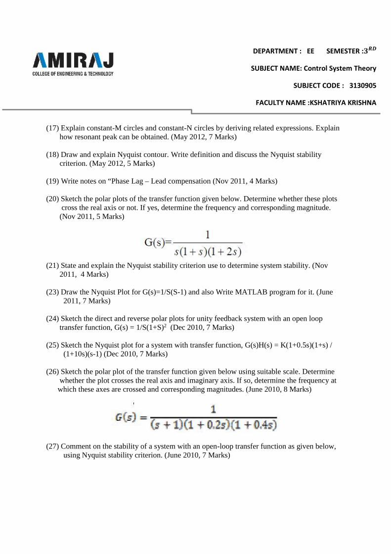
(20) Sketch the polar plots of the transfer function given below. Determine whether these plotscross the real axis or not. If yes, determine the frequency and corresponding magnitude.(Nov 2011, 5 Marks)
(21) State and explain the Nyquist stability criterion use to determine system stability. (Nov2011, 4 Marks)
(23) Draw the Nyquist Plot for G(s)=1/S(S-1) and also Write MATLAB program for it. (June2011, 7 Marks)
(24) Sketch the direct and reverse polar plots for unity feedback system with an open looptransfer function, G(s) = 1/S(1+S)2 (Dec 2010, 7 Marks)
(25) Sketch the Nyquist plot for a system with transfer function, G(s)H(s) = K(1+0.5s)(1+s) /(1+10s)(s-1) (Dec 2010, 7 Marks)
(26) Sketch the polar plot of the transfer function given below using suitable scale. Determinewhether the plot crosses the real axis and imaginary axis. If so, determine the frequency atwhich these axes are crossed and corresponding magnitudes. (June 2010, 8 Marks)
(27) Comment on the stability of a system with an open-loop transfer function as given below,using Nyquist stability criterion. (June 2010, 7 Marks)

DEPARTMENT : EE SEMESTER :
SUBJECT NAME: Control System Theory
SUBJECT CODE : 3130905
FACULTY NAME :KSHATRIYA KRISHNA
(28) Explain constant-M circles and constant-N circles by deriving related expressions. Explainhow resonant peak can be obtained. (June 2010, 7 Marks)