Ch 1 the x86 µprocessor
48
The x86 PC Assembly Langu11age, Design, and Interfacing By Muhammad Ali Mazidi, Janice Gillespie Mazidi and Danny Causey 1 ORG ; ONE Dec Hex Bin 1 1 00000001 The x86 Microprocessor The x86 PC Assembly Langu22age, Design, and Interfacing By Muhammad Ali Mazidi, Janice Gillespie Mazidi and Danny Causey 2 1.1 BRIEF HISTORY OF THE x86 FAMILY evolution from 8080/8085 to 8086 • In 1978, Intel Corporation introduced the 16-bit 8086 microprocessor, a major improvement over the previous generation 8080/8085 series. – The 8086 capacity of 1 megabyte of memory exceeded the 8080/8085 maximum of 64K bytes of memory. – 8080/8085 was an 8-bit system, which could work on only 8 bits of data at a time. • Data larger than 8 bits had to be broken into 8-bit pieces to be processed by the CPU. – 8086 was a pipelined processor, as opposed to the nonpipelined 8080/8085. 2
-
Upload
abd-asalam-saber -
Category
Art & Photos
-
view
241 -
download
0
Transcript of Ch 1 the x86 µprocessor
The x86 PCAssembly Langu11age, Design, and InterfacingBy Muhammad Ali Mazidi, Janice Gillespie Mazidi and Danny Causey
1
ORG ; ONE
Dec Hex Bin
1 1 00000001
The x86Microprocessor
The x86 PCAssembly Langu22age, Design, and InterfacingBy Muhammad Ali Mazidi, Janice Gillespie Mazidi and Danny Causey
2
1.1 BRIEF HISTORY OF THE x86 FAMILY evolution from 8080/8085 to 8086
• In 1978, Intel Corporation introduced the 16-bit 8086 microprocessor, a major improvement over the previous generation 8080/8085 series.– The 8086 capacity of 1 megabyte of memory exceeded
the 8080/8085 maximum of 64K bytes of memory.
– 8080/8085 was an 8-bit system, which could work ononly 8 bits of data at a time.
• Data larger than 8 bits had to be broken into 8-bit piecesto be processed by the CPU.
– 8086 was a pipelined processor, as opposed to the nonpipelined 8080/8085.
2

The x86 PCAssembly Langu33age, Design, and InterfacingBy Muhammad Ali Mazidi, Janice Gillespie Mazidi and Danny Causey
3
1.1 BRIEF HISTORY OF THE x86 FAMILY evolution from 8080/8085 to 8086
The x86 PCAssembly Langu44age, Design, and InterfacingBy Muhammad Ali Mazidi, Janice Gillespie Mazidi and Danny Causey
4
1.1 BRIEF HISTORY OF THE x86 FAMILY evolution from 8086 to 8088
• The 8086 microprocessor has a 16-bit data bus, internally and externally.– All registers are 16 bits wide, and there is a 16-bit
data bus to transfer data in and out of the CPU• There was resistance to a 16-bit external bus as
peripherals were designed around 8-bit processors.
• A printed circuit board with a 16-bit data also bus cost more.
• As a result, Intel came out with the 8088 version.– Identical to the 8086, but with an 8-bit data bus.
• Picked up by IBM as the microprocessor in designing the PC.

The x86 PCAssembly Langu55age, Design, and InterfacingBy Muhammad Ali Mazidi, Janice Gillespie Mazidi and Danny Causey
5
1.1 BRIEF HISTORY OF THE x86 FAMILY 80286, 80386, and 80486
The x86 PCAssembly Langu66age, Design, and InterfacingBy Muhammad Ali Mazidi, Janice Gillespie Mazidi and Danny Causey
6
1.1 BRIEF HISTORY OF THE x86 FAMILY Pentium® & Pentium® Pro

The x86 PCAssembly Langu77age, Design, and InterfacingBy Muhammad Ali Mazidi, Janice Gillespie Mazidi and Danny Causey
7
1.2 INSIDE THE 8088/86
Figure 1-1Internal Block Diagram of the 8088/86 CPU(Reprinted by permission of Intel Corporation,Copyright Intel Corp.1989)
• There are two ways tomake the CPU processinformation faster:– Increase the working
frequency.• Using technology
available, with cost considerations.
– Change the internalarchitecture of the CPU.
The x86 PCAssembly Langu88age, Design, and InterfacingBy Muhammad Ali Mazidi, Janice Gillespie Mazidi and Danny Causey
8
1.2 INSIDE THE 8088/86 pipelining
• 8085 could fetch or execute at any given time.– The idea of pipelining in its simplest form is to allow the
CPU to fetch and execute at the same time.
Figure 1-2 Pipelined vs Nonpipelined Execution
The x86 PCAssembly Langu99age, Design, and InterfacingBy Muhammad Ali Mazidi, Janice Gillespie Mazidi and Danny Causey
9
1.2 INSIDE THE 8088/86registers
• In the CPU, registers store information temporarily.– One or two bytes of data to be processed.
– The address of data.
• General-purpose registers in 8088/86 processors can be accessed as either 16-bit or 8-bit registers– All other registers can be accessed only
as the full 16 bits.
• In 8088/86, data types are either 8 or 16 bits– To access 12-bit data, for example, a 16-bit register
must be used with the highest 4 bits set to 0.
The x86 PCAssembly Langu1010age, Design, and InterfacingBy Muhammad Ali Mazidi, Janice Gillespie Mazidi and Danny Causey
10
1.2 INSIDE THE 8088/86registers
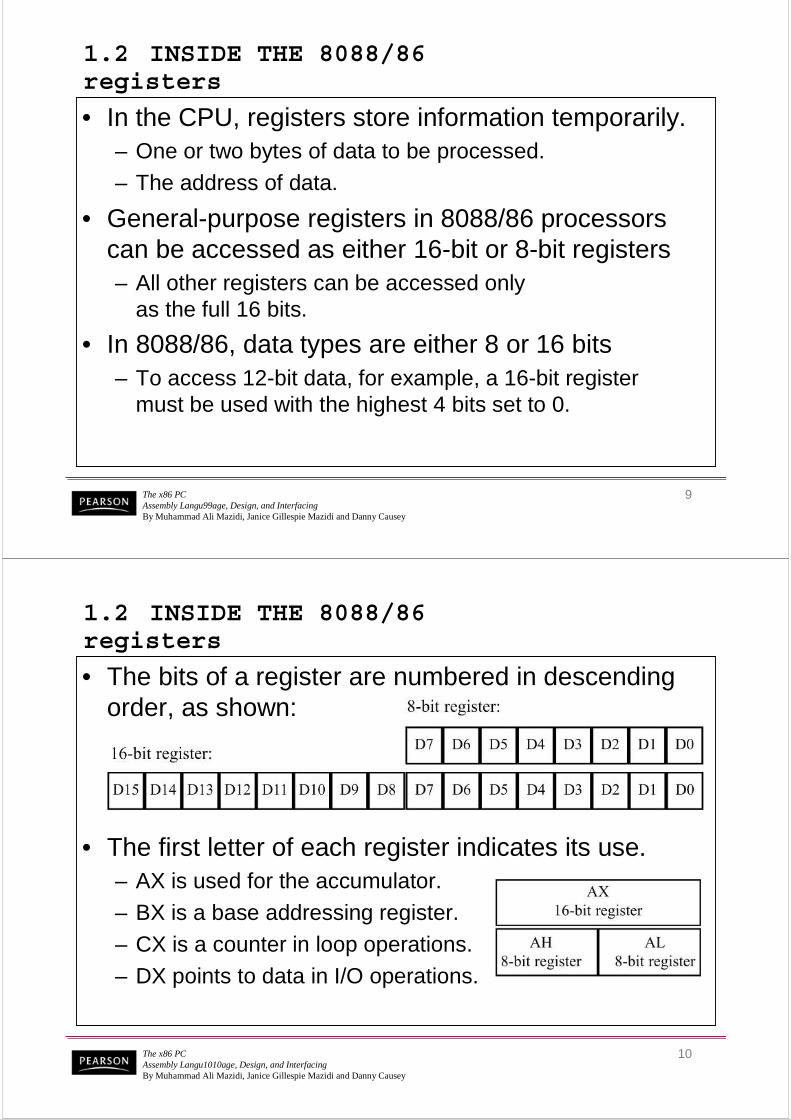
• The bits of a register are numbered in descending order, as shown:
• The first letter of each register indicates its use.– AX is used for the accumulator.
– BX is a base addressing register.
– CX is a counter in loop operations.
– DX points to data in I/O operations.

The x86 PCAssembly Langu1111age, Design, and InterfacingBy Muhammad Ali Mazidi, Janice Gillespie Mazidi and Danny Causey
11
1.2 INSIDE THE 8088/86registers
The x86 PCAssembly Langu1212age, Design, and InterfacingBy Muhammad Ali Mazidi, Janice Gillespie Mazidi and Danny Causey
12
1.3 INTRODUCTION TO ASSEMBLY PROGRAMMING
• The CPU can work only in binary, very high speeds.– It is tedious & slow for humans to deal with 0s & 1s in
order to program the computer.
• A program of 0s & 1s is called machine language.– Early computer programmers actually coded programs
in machine language.
• Eventually, Assembly languages were developed, which provided mnemonics for machine code.– Mnemonic is typically used in computer science and
engineering literature to refer to codes & abbreviations that are relatively easy to remember.

The x86 PCAssembly Langu1313age, Design, and InterfacingBy Muhammad Ali Mazidi, Janice Gillespie Mazidi and Danny Causey
13
1.3 INTRODUCTION TO ASSEMBLY PROGRAMMING
• Assembly language is referred to as a low-levellanguage because it deals directly with the internal structure of the CPU.– Assembly language programs must be translated into
machine code by a program called an assembler.
– To program in Assembly language, programmersmust know the number of registers and their size.
• As well as other details of the CPU.
The x86 PCAssembly Langu1414age, Design, and InterfacingBy Muhammad Ali Mazidi, Janice Gillespie Mazidi and Danny Causey
14
1.3 INTRODUCTION TO ASSEMBLY PROGRAMMING
• There are numerous assemblers available for translating x86 Assembly language programsinto machine code.– One of the most commonly used assemblers is
MASM by Microsoft.
• The present chapter is designed to correspond to Appendix A: DEBUG Programming.– Provided with the Microsoft Windows operating system.

The x86 PCAssembly Langu1515age, Design, and InterfacingBy Muhammad Ali Mazidi, Janice Gillespie Mazidi and Danny Causey
15
1.3 INTRODUCTION TO ASSEMBLY PROGRAMMING assembly language programming
• An Assembly language program consists of a series of lines of Assembly language instructions.
• An Assembly language instruction consists of a mnemonic, optionally followed by one or two operands.– Operands are the data items being manipulated.
– Mnemonics are commands to the CPU, telling itwhat to do with those items.
• Two widely used instructions are move & add.
The x86 PCAssembly Langu1616age, Design, and InterfacingBy Muhammad Ali Mazidi, Janice Gillespie Mazidi and Danny Causey
16
1.3 INTRODUCTION TO ASSEMBLY PROGRAMMING MOV instruction
• The MOV instruction copies data from one location to another, using this format:
• This instruction tells the CPU to move (in reality, copy) the source operand to the destination operand. – For example, the instruction "MOV DX,CX" copies the
contents of register CX to register DX.
– After this instruction is executed, register DX will havethe same value as register CX.

The x86 PCAssembly Langu1717age, Design, and InterfacingBy Muhammad Ali Mazidi, Janice Gillespie Mazidi and Danny Causey
17
1.3 INTRODUCTION TO ASSEMBLY PROGRAMMING MOV instruction
• This program first loads CL with value 55H, then moves this value around to various registersinside the CPU.
The x86 PCAssembly Langu1818age, Design, and InterfacingBy Muhammad Ali Mazidi, Janice Gillespie Mazidi and Danny Causey
18
1.3 INTRODUCTION TO ASSEMBLY PROGRAMMING MOV instruction
• The use of 16-bit registers is shown here:

The x86 PCAssembly Langu1919age, Design, and InterfacingBy Muhammad Ali Mazidi, Janice Gillespie Mazidi and Danny Causey
19
1.3 INTRODUCTION TO ASSEMBLY PROGRAMMING MOV instruction
• In the 8086 CPU, data can be moved among all the registers, as long as the source and destination registers match in size (Except the flag register.)– There is no such instruction as "MOV FR,AX“.
• Code such as "MOV ALAL,,DXDX" will cause an error.– One cannot move the contents of a 16-bit register
into an 8-bit register.
The x86 PCAssembly Langu2020age, Design, and InterfacingBy Muhammad Ali Mazidi, Janice Gillespie Mazidi and Danny Causey
20
1.3 INTRODUCTION TO ASSEMBLY PROGRAMMING MOV instruction
• Using the MOV instruction, data can be moved directly into nonsegment registers only.– The following demonstrates legal & illegal instructions.

The x86 PCAssembly Langu2121age, Design, and InterfacingBy Muhammad Ali Mazidi, Janice Gillespie Mazidi and Danny Causey
21
1.3 INTRODUCTION TO ASSEMBLY PROGRAMMING MOV instruction
• Values cannot be loaded directly into any segment register (CS, DS, ES, or SS).– To load a value into a segment register, load it to a non-
segment register, then move it to the segment register.
The x86 PCAssembly Langu2222age, Design, and InterfacingBy Muhammad Ali Mazidi, Janice Gillespie Mazidi and Danny Causey
22
1.3 INTRODUCTION TO ASSEMBLY PROGRAMMING MOV instruction
• If a value less than FFH is moved into a 16-bit register, the rest of the bits are assumed to be zeros.– For example, in "MOV BX,5" the result will be BX = 0005.
• BH = 00 and BL = 05.
• Moving a value that is too large into a register will cause an error.

The x86 PCAssembly Langu2323age, Design, and InterfacingBy Muhammad Ali Mazidi, Janice Gillespie Mazidi and Danny Causey
23
1.3 INTRODUCTION TO ASSEMBLY PROGRAMMING ADD instruction
– Executing the program above results in:AL = 59H (25H + 34H = 59H) and BL = 34H.
• The contents of BL do not change.
• The ADD instruction has the following format:
• ADD tells the CPU to add the source & destination operands and put the result in the destination.– To add two numbers such as 25H and 34H, each can
be moved to a register, then added together:
The x86 PCAssembly Langu2424age, Design, and InterfacingBy Muhammad Ali Mazidi, Janice Gillespie Mazidi and Danny Causey
24
1.3 INTRODUCTION TO ASSEMBLY PROGRAMMING ADD instruction
• The program above can be written in many ways, depending on the registers used, such as:
– The program above results in DH = 59Hand CL = 34H.
The x86 PCAssembly Langu2525age, Design, and InterfacingBy Muhammad Ali Mazidi, Janice Gillespie Mazidi and Danny Causey
25
1.3 INTRODUCTION TO ASSEMBLY PROGRAMMING ADD instruction
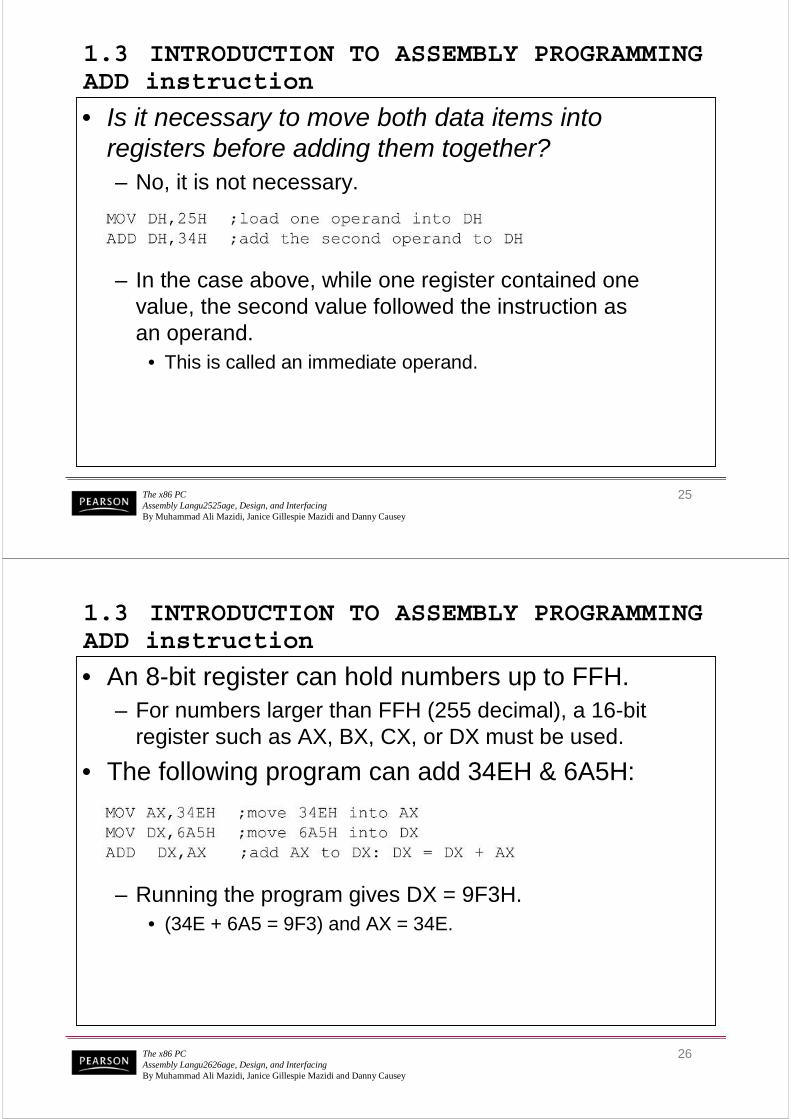
• Is it necessary to move both data items into registers before adding them together?– No, it is not necessary.
– In the case above, while one register contained one value, the second value followed the instruction asan operand.
• This is called an immediate operand.
The x86 PCAssembly Langu2626age, Design, and InterfacingBy Muhammad Ali Mazidi, Janice Gillespie Mazidi and Danny Causey
26
1.3 INTRODUCTION TO ASSEMBLY PROGRAMMING ADD instruction
• An 8-bit register can hold numbers up to FFH.– For numbers larger than FFH (255 decimal), a 16-bit
register such as AX, BX, CX, or DX must be used.
• The following program can add 34EH & 6A5H:
– Running the program gives DX = 9F3H.• (34E + 6A5 = 9F3) and AX = 34E.
The x86 PCAssembly Langu2727age, Design, and InterfacingBy Muhammad Ali Mazidi, Janice Gillespie Mazidi and Danny Causey
27
1.3 INTRODUCTION TO ASSEMBLY PROGRAMMING ADD instruction
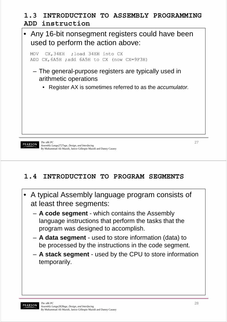
• Any 16-bit nonsegment registers could have been used to perform the action above:
– The general-purpose registers are typically used in arithmetic operations
• Register AX is sometimes referred to as the accumulator.
The x86 PCAssembly Langu2828age, Design, and InterfacingBy Muhammad Ali Mazidi, Janice Gillespie Mazidi and Danny Causey
28
1.4 INTRODUCTION TO PROGRAM SEGMENTS
• A typical Assembly language program consists ofat least three segments:– A code segment - which contains the Assembly
language instructions that perform the tasks that the program was designed to accomplish.
– A data segment - used to store information (data) tobe processed by the instructions in the code segment.
– A stack segment - used by the CPU to store information temporarily.
The x86 PCAssembly Langu2929age, Design, and InterfacingBy Muhammad Ali Mazidi, Janice Gillespie Mazidi and Danny Causey
29
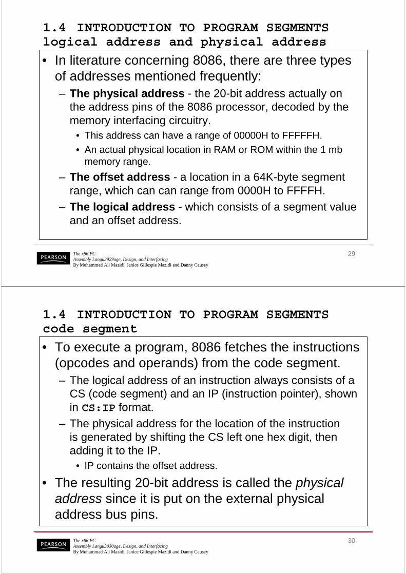
1.4 INTRODUCTION TO PROGRAM SEGMENTS logical address and physical address
• In literature concerning 8086, there are three types of addresses mentioned frequently:– The physical address - the 20-bit address actually on
the address pins of the 8086 processor, decoded by the memory interfacing circuitry.
• This address can have a range of 00000H to FFFFFH.
• An actual physical location in RAM or ROM within the 1 mb memory range.
– The offset address - a location in a 64K-byte segment range, which can can range from 0000H to FFFFH.
– The logical address - which consists of a segment value and an offset address.
The x86 PCAssembly Langu3030age, Design, and InterfacingBy Muhammad Ali Mazidi, Janice Gillespie Mazidi and Danny Causey
30
1.4 INTRODUCTION TO PROGRAM SEGMENTS code segment
• To execute a program, 8086 fetches the instructions (opcodes and operands) from the code segment.– The logical address of an instruction always consists of a
CS (code segment) and an IP (instruction pointer), shown in CS:IP format.
– The physical address for the location of the instructionis generated by shifting the CS left one hex digit, then adding it to the IP.
• IP contains the offset address.
• The resulting 20-bit address is called the physical address since it is put on the external physical address bus pins.

The x86 PCAssembly Langu3131age, Design, and InterfacingBy Muhammad Ali Mazidi, Janice Gillespie Mazidi and Danny Causey
31
1.4 INTRODUCTION TO PROGRAM SEGMENTS code segment
• Assume values in CS & IP as shown in the diagram:
– The offset address contained in IP, is 95F3H.
– The logical address is CS:IP, or 2500:95F3H.
– The physical address will be 25000 + 95F3 = 2E5F3H
The x86 PCAssembly Langu3232age, Design, and InterfacingBy Muhammad Ali Mazidi, Janice Gillespie Mazidi and Danny Causey
32
1.4 INTRODUCTION TO PROGRAM SEGMENTS code segment
• Calculate the physical address of an instruction:
– The microprocessor will retrieve the instruction from memory locations starting at 2E5F3.

The x86 PCAssembly Langu3333age, Design, and InterfacingBy Muhammad Ali Mazidi, Janice Gillespie Mazidi and Danny Causey
33
1.4 INTRODUCTION TO PROGRAM SEGMENTS code segment
• Calculate the physical address of an instruction:
– Since IP can have a minimum value of 0000H and a maximum of FFFFH, the logical address range in this example is 2500:0000 to 2500:FFFF.
The x86 PCAssembly Langu3434age, Design, and InterfacingBy Muhammad Ali Mazidi, Janice Gillespie Mazidi and Danny Causey
34
– This means that the lowest memory location of the code segment above will be 25000H (25000 + 0000) and the highest memory location will be 34FFFH (25000 + FFFF).
1.4 INTRODUCTION TO PROGRAM SEGMENTS code segment
• Calculate the physical address of an instruction:
The x86 PCAssembly Langu3535age, Design, and InterfacingBy Muhammad Ali Mazidi, Janice Gillespie Mazidi and Danny Causey
35
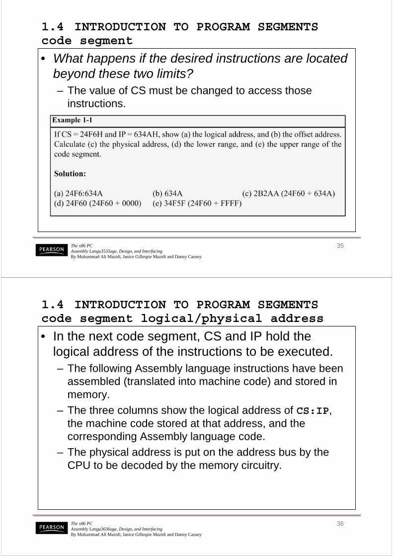
1.4 INTRODUCTION TO PROGRAM SEGMENTS code segment
• What happens if the desired instructions are located beyond these two limits? – The value of CS must be changed to access those
instructions.
The x86 PCAssembly Langu3636age, Design, and InterfacingBy Muhammad Ali Mazidi, Janice Gillespie Mazidi and Danny Causey
36
1.4 INTRODUCTION TO PROGRAM SEGMENTS code segment logical/physical address
• In the next code segment, CS and IP hold the logical address of the instructions to be executed.– The following Assembly language instructions have been
assembled (translated into machine code) and stored in memory.
– The three columns show the logical address of CS:IP, the machine code stored at that address, and the corresponding Assembly language code.
– The physical address is put on the address bus by the CPU to be decoded by the memory circuitry.

The x86 PCAssembly Langu3737age, Design, and InterfacingBy Muhammad Ali Mazidi, Janice Gillespie Mazidi and Danny Causey
37
1.4 INTRODUCTION TO PROGRAM SEGMENTS code segment logical/physical address
Instruction "MOV AL,57" has a machine code of B057.
B0 is the opcode and 57 is the operand.
The x86 PCAssembly Langu3838age, Design, and InterfacingBy Muhammad Ali Mazidi, Janice Gillespie Mazidi and Danny Causey
38
1.4 INTRODUCTION TO PROGRAM SEGMENTS code segment logical/physical address
Instruction "MOV AL,57" has a machine code of B057.
B0 is the opcode and 57 is the operand.
The byte at address 1132:0100 contains B0, the opcode for movinga value into register AL.
Address 1132:0101 contains the operand to be moved to AL.

The x86 PCAssembly Langu3939age, Design, and InterfacingBy Muhammad Ali Mazidi, Janice Gillespie Mazidi and Danny Causey
39
1.4 INTRODUCTION TO PROGRAM SEGMENTS data segment
• Assume a program to add 5 bytes of data, such as 25H, 12H, 15H, 1FH, and 2BH.– One way to add them is as follows:
– In the program above, the data & code are mixed together in the instructions.
• If the data changes, the code must be searched for every place it is included, and the data retyped
• From this arose the idea of an area of memory strictly for data
The x86 PCAssembly Langu4040age, Design, and InterfacingBy Muhammad Ali Mazidi, Janice Gillespie Mazidi and Danny Causey
40
1.4 INTRODUCTION TO PROGRAM SEGMENTS data segment
• Assume data segment offset begins at 200H.– The data is placed in memory locations:
– The program can be rewritten as follows:
The x86 PCAssembly Langu4141age, Design, and InterfacingBy Muhammad Ali Mazidi, Janice Gillespie Mazidi and Danny Causey
41
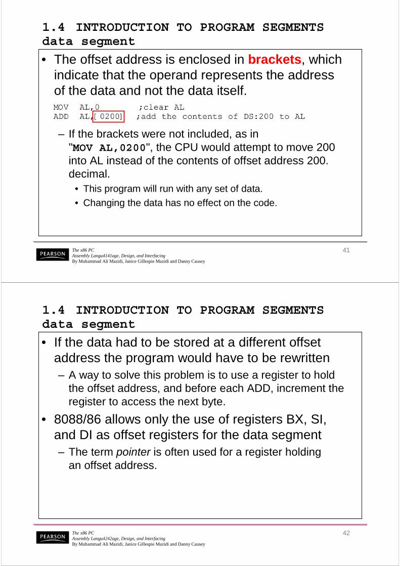
1.4 INTRODUCTION TO PROGRAM SEGMENTS data segment
• The offset address is enclosed in brackets, which indicate that the operand represents the addressof the data and not the data itself.
– If the brackets were not included, as in "MOV AL,0200", the CPU would attempt to move 200 into AL instead of the contents of offset address 200. decimal.
• This program will run with any set of data.
• Changing the data has no effect on the code.
The x86 PCAssembly Langu4242age, Design, and InterfacingBy Muhammad Ali Mazidi, Janice Gillespie Mazidi and Danny Causey
42
1.4 INTRODUCTION TO PROGRAM SEGMENTS data segment
• If the data had to be stored at a different offset address the program would have to be rewritten– A way to solve this problem is to use a register to hold
the offset address, and before each ADD, increment the register to access the next byte.
• 8088/86 allows only the use of registers BX, SI, and DI as offset registers for the data segment– The term pointer is often used for a register holding
an offset address.

The x86 PCAssembly Langu4343age, Design, and InterfacingBy Muhammad Ali Mazidi, Janice Gillespie Mazidi and Danny Causey
43
1.4 INTRODUCTION TO PROGRAM SEGMENTS data segment
• In the following example, BXBX is used as a pointer:
• The INCINC instruction adds 1 to (increments) its operand.– "INC BX" achieves the same result as "ADD BX,1“
– If the offset address where data is located is changed, only one instruction will need to be modified.
The x86 PCAssembly Langu4444age, Design, and InterfacingBy Muhammad Ali Mazidi, Janice Gillespie Mazidi and Danny Causey
44
1.4 INTRODUCTION TO PROGRAM SEGMENTS data segment logical/physical address
• The physical address for data is calculated using the same rules as for the code segment.– The physical address of data is calculated by shifting DS
left one hex digit and adding the offset value, as shownin Examples 1-2, 1-3, and 1-4.

The x86 PCAssembly Langu4545age, Design, and InterfacingBy Muhammad Ali Mazidi, Janice Gillespie Mazidi and Danny Causey
45
1.4 INTRODUCTION TO PROGRAM SEGMENTS data segment logical/physical address
The x86 PCAssembly Langu4646age, Design, and InterfacingBy Muhammad Ali Mazidi, Janice Gillespie Mazidi and Danny Causey
46
1.4 INTRODUCTION TO PROGRAM SEGMENTS data segment logical/physical address
The x86 PCAssembly Langu4747age, Design, and InterfacingBy Muhammad Ali Mazidi, Janice Gillespie Mazidi and Danny Causey
47
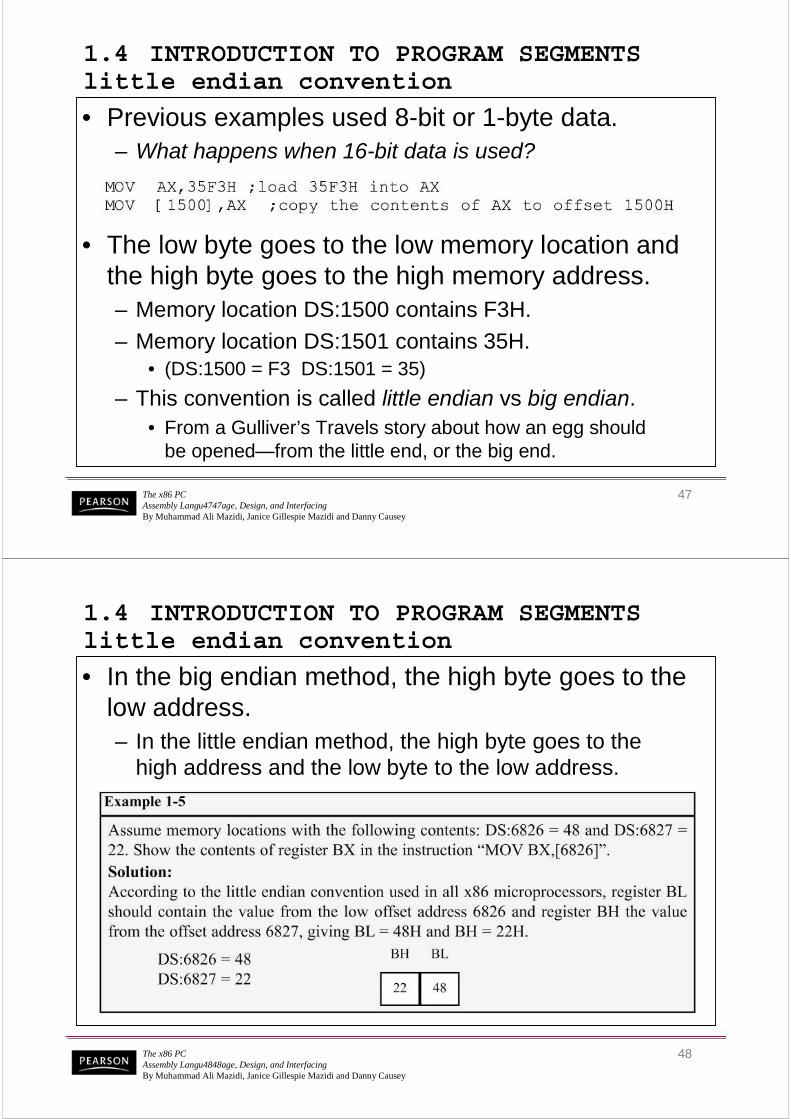
1.4 INTRODUCTION TO PROGRAM SEGMENTS little endian convention
• Previous examples used 8-bit or 1-byte data.– What happens when 16-bit data is used?
• The low byte goes to the low memory location and the high byte goes to the high memory address.– Memory location DS:1500 contains F3H.
– Memory location DS:1501 contains 35H.• (DS:1500 = F3 DS:1501 = 35)
– This convention is called little endian vs big endian.• From a Gulliver’s Travels story about how an egg should
be opened—from the little end, or the big end.
The x86 PCAssembly Langu4848age, Design, and InterfacingBy Muhammad Ali Mazidi, Janice Gillespie Mazidi and Danny Causey
48
1.4 INTRODUCTION TO PROGRAM SEGMENTS little endian convention
• In the big endian method, the high byte goes to the low address.– In the little endian method, the high byte goes to the
high address and the low byte to the low address.

The x86 PCAssembly Langu4949age, Design, and InterfacingBy Muhammad Ali Mazidi, Janice Gillespie Mazidi and Danny Causey
49
1.4 INTRODUCTION TO PROGRAM SEGMENTS extra segment (ES)
• ES is a segment register used as an extra data segment.– In many normal programs this segment is not used.
– Use is essential for string operations.
The x86 PCAssembly Langu5050age, Design, and InterfacingBy Muhammad Ali Mazidi, Janice Gillespie Mazidi and Danny Causey
50
1.4 INTRODUCTION TO PROGRAM SEGMENTS memory map of the IBM PC
• The 20-bit address of 8088/86 allows 1mb (1024K bytes) of memory space with the address range 00000–FFFFF.– During the design phase of the first
IBM PC, engineers had to decideon the allocation of the 1-megabyte memory space to various sectionsof the PC.
• This memory allocation iscalled a memory map.
Figure 1-3 Memory Allocation in the PC

The x86 PCAssembly Langu5151age, Design, and InterfacingBy Muhammad Ali Mazidi, Janice Gillespie Mazidi and Danny Causey
51
Figure 1-3 Memory Allocation in the PC
1.4 INTRODUCTION TO PROGRAM SEGMENTS memory map of the IBM PC
• Of this 1 megabyte, 640K bytes from addresses 0000000000––9FFFFH9FFFFHwere set aside for RAM
• 128K bytes A0000HA0000H–– BFFFFHBFFFFHwere allocated for video memory
• The remaining 256K bytes from C0000HC0000H––FFFFFHFFFFFH were set aside for ROM
The x86 PCAssembly Langu5252age, Design, and InterfacingBy Muhammad Ali Mazidi, Janice Gillespie Mazidi and Danny Causey
52
1.4 INTRODUCTION TO PROGRAM SEGMENTS more about RAM
• In the early 80s, most PCs came with 64K to 256K bytes of RAM, more than adequate at the time– Users had to buy memory to expand up to 640K.
• Managing RAM is left to Windows because...– The amount of memory used by Windows varies.– Different computers have different amounts of RAM.– Memory needs of application packages vary.
• For this reason, we do not assign any values for the CS, DS, and SS registers.– Such an assignment means specifying an exact physical
address in the range 00000–9FFFFH, and this is beyond the knowledge of the user.

The x86 PCAssembly Langu5353age, Design, and InterfacingBy Muhammad Ali Mazidi, Janice Gillespie Mazidi and Danny Causey
53
1.4 INTRODUCTION TO PROGRAM SEGMENTS more about ROM
• C0000H to FFFFFH is set aside for ROM.– Not all the memory in this range is used by the PC's ROM.
• 64K bytes from location F0000H–FFFFFH areused by BIOS (basic input/output system) ROM.– Some of the remaining space is used by various adapter
cards (such as the network card), and the rest is free.
• The 640K bytes from 00000 to 9FFFFH is referredto as conventional memory.– The 384K bytes from A0000H to FFFFFH are called
the UMB (upper memory block).
The x86 PCAssembly Langu5454age, Design, and InterfacingBy Muhammad Ali Mazidi, Janice Gillespie Mazidi and Danny Causey
54
1.5 THE STACK what is a stack? why is it needed?
• The stack is a section of read/write memory (RAM) used by the CPU to store information temporarily.– The CPU needs this storage area since there are
only a limited number of registers.• There must be some place for the CPU to store
information safely and temporarily.
• The main disadvantage of the stack is access time.– Since the stack is in RAM, it takes much longer to
access compared to the access time of registers.
• Some very powerful (expensive) computers do not have a stack.– The CPU has a large number of registers to work with.

The x86 PCAssembly Langu5555age, Design, and InterfacingBy Muhammad Ali Mazidi, Janice Gillespie Mazidi and Danny Causey
55
1.5 THE STACK how stacks are accessed
• The stack is a section of RAM, so there must be registers inside the CPU to point to it.– The SS (stack segment) register.
– The SP (stack pointer) register.• These registers must be loaded before any
instructions accessing the stack are used.
• Every register inside the x86 can be stored in the stack, and brought back into the CPU from thestack memory, except segment registers and SP.– Storing a CPU register in the stack is called a push.
– Loading the contents of the stack into the CPU registeris called a pop.
The x86 PCAssembly Langu5656age, Design, and InterfacingBy Muhammad Ali Mazidi, Janice Gillespie Mazidi and Danny Causey
56
1.5 THE STACK how stacks are accessed
• The x86 stack pointer register (SP) points at the current memory location used as the top of the stack.– As data is pushed onto the stack it is decremented.
– As data is popped off the stack into the CPU, it is incremented.
• When an instruction pushes or pops a general-purpose register, it must be the entire 16-bit register.– One must code "PUSH AX".
• There are no instructions such as "PUSH AL" or "PUSH AH".

The x86 PCAssembly Langu5757age, Design, and InterfacingBy Muhammad Ali Mazidi, Janice Gillespie Mazidi and Danny Causey
57
1.5 THE STACK how stacks are accessed
• The SP is decremented after the push is to make sure the stack is growing downward from upper addresses to lower addresses.– The opposite of the IP. (instruction pointer)
• To ensure the code section & stack section of the program never write over each other, they arelocated at opposite ends of the RAM set asidefor the program.– They grow toward each other but must not meet.
• If they meet, the program will crash.
The x86 PCAssembly Langu5858age, Design, and InterfacingBy Muhammad Ali Mazidi, Janice Gillespie Mazidi and Danny Causey
58
1.5 THE STACK pushing onto the stack
• As each PUSH is executed, the register contents are saved on the stack and SP is decremented by 2.
The x86 PCAssembly Langu5959age, Design, and InterfacingBy Muhammad Ali Mazidi, Janice Gillespie Mazidi and Danny Causey
59
1.5 THE STACK pushing onto the stack
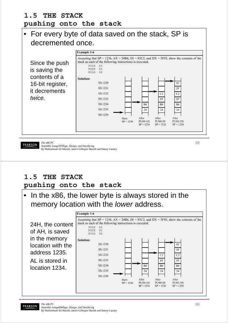
• For every byte of data saved on the stack, SP is decremented once.
Since the pushis saving the contents of a16-bit register,it decrements twice.
The x86 PCAssembly Langu6060age, Design, and InterfacingBy Muhammad Ali Mazidi, Janice Gillespie Mazidi and Danny Causey
60
1.5 THE STACK pushing onto the stack
• In the x86, the lower byte is always stored in the memory location with the lower address.
24H, the content of AH, is savedin the memory location with the address 1235.
AL is stored in location 1234.

The x86 PCAssembly Langu6161age, Design, and InterfacingBy Muhammad Ali Mazidi, Janice Gillespie Mazidi and Danny Causey
61
1.5 THE STACK popping the stack
• With every pop, the top 2 bytes of the stack are copied to the x86 CPU register specified by the instruction & the stack pointer is incremented twice.
While the data actually remains in memory, it is not accessible, since the stack pointer, SP is beyond that point.
The x86 PCAssembly Langu6262age, Design, and InterfacingBy Muhammad Ali Mazidi, Janice Gillespie Mazidi and Danny Causey
62
1.5 THE STACK logical vs physical stack address
• The exact physical location of the stack depends on the value of the stack segment (SS) register andSP, the stack pointer.– To compute physical addresses for the stack, shift
left SS, then add offset SP, the stack pointer register.
– Windows assigns values for the SP and SS.
The x86 PCAssembly Langu6363age, Design, and InterfacingBy Muhammad Ali Mazidi, Janice Gillespie Mazidi and Danny Causey
63
1.5 THE STACKa few more words about x86 segments
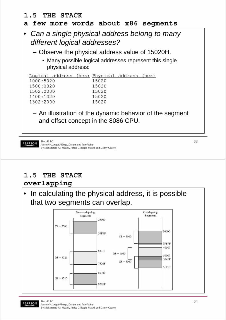
• Can a single physical address belong to many different logical addresses? – Observe the physical address value of 15020H.
• Many possible logical addresses represent this singlephysical address:
– An illustration of the dynamic behavior of the segment and offset concept in the 8086 CPU.
The x86 PCAssembly Langu6464age, Design, and InterfacingBy Muhammad Ali Mazidi, Janice Gillespie Mazidi and Danny Causey
64
1.5 THE STACKoverlapping
• In calculating the physical address, it is possible that two segments can overlap.

The x86 PCAssembly Langu6565age, Design, and InterfacingBy Muhammad Ali Mazidi, Janice Gillespie Mazidi and Danny Causey
65
1.6 FLAG REGISTER
• Many Assembly language instructions alter flag register bits & some instructions function differently based on the information in the flag register.
• The flag register is a 16-bit register sometimes referred to as the status register.– Although 16 bits wide, only some of the bits are used.
• The rest are either undefined or reserved by Intel.
The x86 PCAssembly Langu6666age, Design, and InterfacingBy Muhammad Ali Mazidi, Janice Gillespie Mazidi and Danny Causey
66
1.6 FLAG REGISTER
• Six flags, called conditional flags, indicate some condition resulting after an instruction executes.
– These six are CFCF, PFPF, AFAF, ZFZF, SFSF, and OFOF.
– The remaining three, often called control flags, controlthe operation of instructions before they are executed.
The x86 PCAssembly Langu6767age, Design, and InterfacingBy Muhammad Ali Mazidi, Janice Gillespie Mazidi and Danny Causey
67
1.6 FLAG REGISTER bits of the flag register
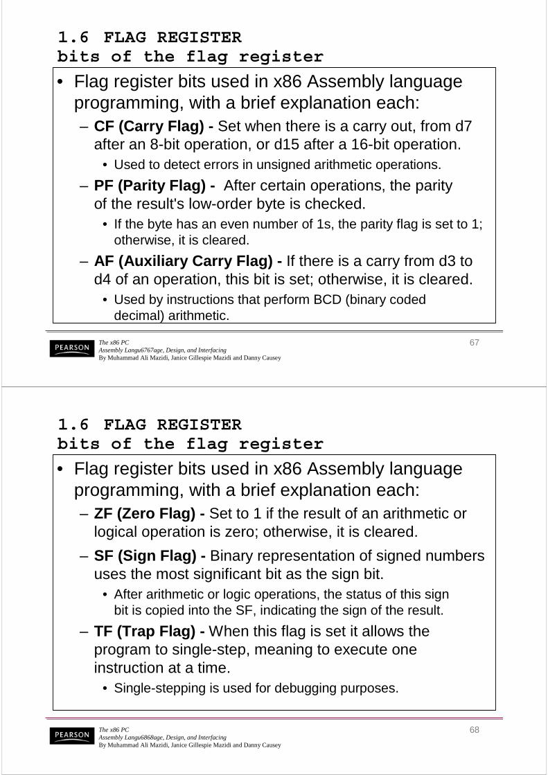
• Flag register bits used in x86 Assembly language programming, with a brief explanation each:– CF (Carry Flag) - Set when there is a carry out, from d7
after an 8-bit operation, or d15 after a 16-bit operation.• Used to detect errors in unsigned arithmetic operations.
– PF (Parity Flag) - After certain operations, the parityof the result's low-order byte is checked.
• If the byte has an even number of 1s, the parity flag is set to 1; otherwise, it is cleared.
– AF (Auxiliary Carry Flag) - If there is a carry from d3 to d4 of an operation, this bit is set; otherwise, it is cleared.
• Used by instructions that perform BCD (binary codeddecimal) arithmetic.
The x86 PCAssembly Langu6868age, Design, and InterfacingBy Muhammad Ali Mazidi, Janice Gillespie Mazidi and Danny Causey
68
1.6 FLAG REGISTER bits of the flag register
• Flag register bits used in x86 Assembly language programming, with a brief explanation each:– ZF (Zero Flag) - Set to 1 if the result of an arithmetic or
logical operation is zero; otherwise, it is cleared.
– SF (Sign Flag) - Binary representation of signed numbers uses the most significant bit as the sign bit.
• After arithmetic or logic operations, the status of this signbit is copied into the SF, indicating the sign of the result.
– TF (Trap Flag) - When this flag is set it allows the program to single-step, meaning to execute one instruction at a time.
• Single-stepping is used for debugging purposes.

The x86 PCAssembly Langu6969age, Design, and InterfacingBy Muhammad Ali Mazidi, Janice Gillespie Mazidi and Danny Causey
69
1.6 FLAG REGISTER bits of the flag register
• Flag register bits used in x86 Assembly language programming, with a brief explanation each:– IF (Interrupt Enable Flag) - This bit is set or cleared to
enable/disable only external maskable interrupt requests.
– DF (Direction Flag) - Used to control the direction of string operations.
– OF (Overflow Flag) - Set when the result of a signed number operation is too large, causing the high-orderbit to overflow into the sign bit.
• Used only to detect errors in signed arithmetic operations.
The x86 PCAssembly Langu7070age, Design, and InterfacingBy Muhammad Ali Mazidi, Janice Gillespie Mazidi and Danny Causey
70
1.6 FLAG REGISTER flag register and ADD instruction
• Flag bits affected by the ADD instruction:– CF (carry flag); PF (parity flag); AF (auxiliary carry flag).
– ZF (zero flag); SF (sign flag); OF (overflow flag).
The x86 PCAssembly Langu7171age, Design, and InterfacingBy Muhammad Ali Mazidi, Janice Gillespie Mazidi and Danny Causey
71
1.6 FLAG REGISTER flag register and ADD instruction
• Flag bits affected by the ADD instruction:– CF (carry flag); PF (parity flag); AF (auxiliary carry flag).
– ZF (zero flag); SF (sign flag); OF (overflow flag).
The x86 PCAssembly Langu7272age, Design, and InterfacingBy Muhammad Ali Mazidi, Janice Gillespie Mazidi and Danny Causey
72
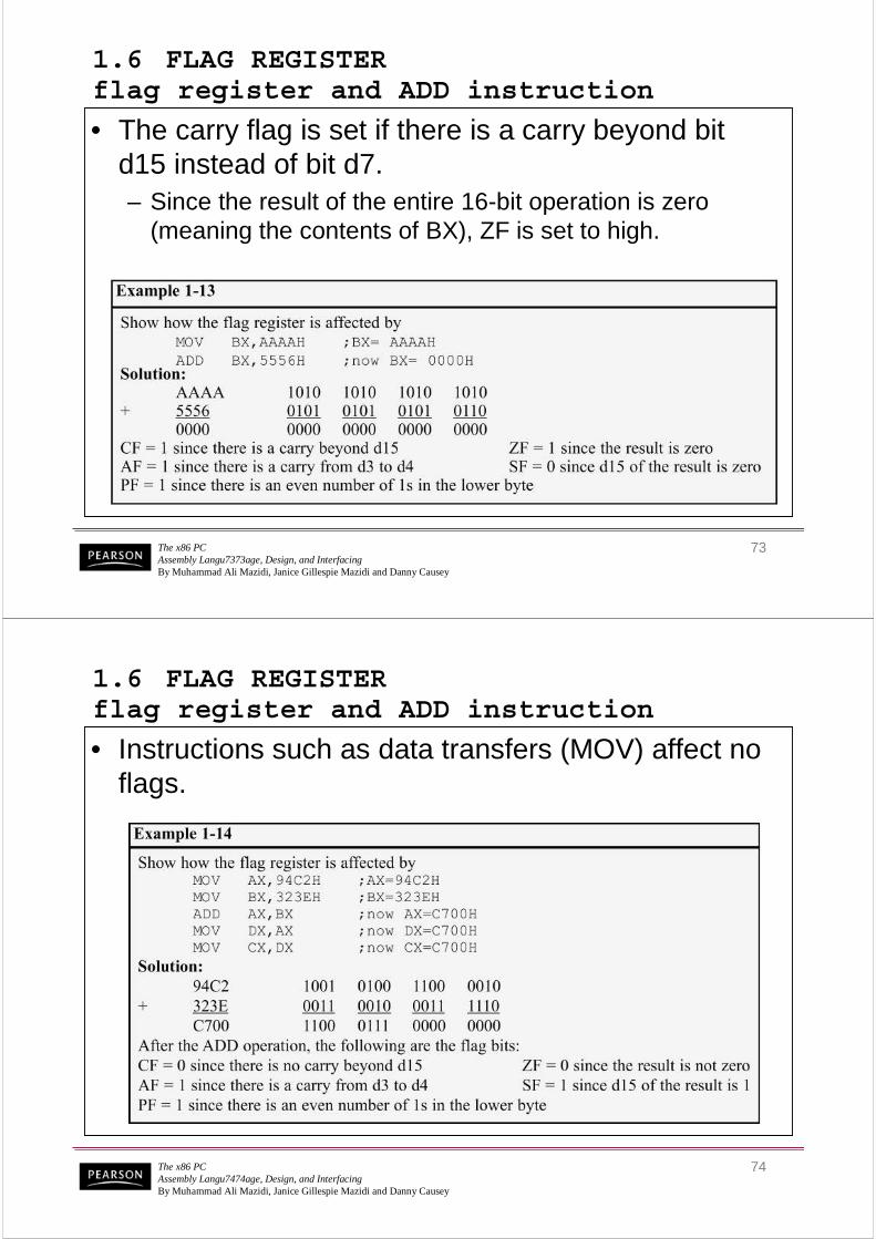
1.6 FLAG REGISTER flag register and ADD instruction
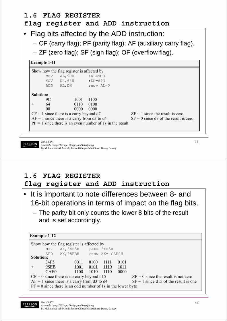
• It is important to note differences between 8- and 16-bit operations in terms of impact on the flag bits.– The parity bit only counts the lower 8 bits of the result
and is set accordingly.
The x86 PCAssembly Langu7373age, Design, and InterfacingBy Muhammad Ali Mazidi, Janice Gillespie Mazidi and Danny Causey
73
1.6 FLAG REGISTER flag register and ADD instruction
• The carry flag is set if there is a carry beyond bit d15 instead of bit d7.– Since the result of the entire 16-bit operation is zero
(meaning the contents of BX), ZF is set to high.
The x86 PCAssembly Langu7474age, Design, and InterfacingBy Muhammad Ali Mazidi, Janice Gillespie Mazidi and Danny Causey
74
1.6 FLAG REGISTER flag register and ADD instruction
• Instructions such as data transfers (MOV) affect no flags.

The x86 PCAssembly Langu7575age, Design, and InterfacingBy Muhammad Ali Mazidi, Janice Gillespie Mazidi and Danny Causey
75
1.6 FLAG REGISTER use of the zero flag for looping
• A widely used application of the flag register is the use of the zero flag to implement program loops.– A loop is a set of instructions repeated a number of times.
The x86 PCAssembly Langu7676age, Design, and InterfacingBy Muhammad Ali Mazidi, Janice Gillespie Mazidi and Danny Causey
76
1.6 FLAG REGISTER use of the zero flag for looping
• As an example, to add 5 bytes of data, a counter can be used to keep track of how many times the loop needs to be repeated.– Each time the addition is performed the counter
is decremented and the zero flag is checked.• When the counter becomes zero, the zero flag is
set (ZF = 1) and the loop is stopped.

The x86 PCAssembly Langu7777age, Design, and InterfacingBy Muhammad Ali Mazidi, Janice Gillespie Mazidi and Danny Causey
77
1.6 FLAG REGISTER use of the zero flag for looping
• Register CXCX is used to hold the counter.– BXBX is the offset pointer.
• (SI or DI could have been used instead)
The x86 PCAssembly Langu7878age, Design, and InterfacingBy Muhammad Ali Mazidi, Janice Gillespie Mazidi and Danny Causey
78
1.6 FLAG REGISTER use of the zero flag for looping
• ALAL is initialized before the start of the loop– In each iteration, ZF is checked by the JNZ JNZ instruction
• JNZ stands for "Jump Not Zero“, meaning that if ZF = 0,jump to a new address.
• If ZF = 1, the jump is not performed, and the instructionbelow the jump will be executed.

The x86 PCAssembly Langu7979age, Design, and InterfacingBy Muhammad Ali Mazidi, Janice Gillespie Mazidi and Danny Causey
79
1.6 FLAG REGISTER use of the zero flag for looping
• JNZJNZ instruction must come immediately after the instruction that decrements CXCX.– JNZ needs to check the effect of "DEC CX" on ZF.
• If any instruction were placed between them, that instruction might affect the zero flag.
The x86 PCAssembly Langu8080age, Design, and InterfacingBy Muhammad Ali Mazidi, Janice Gillespie Mazidi and Danny Causey
80
1.7 x86 ADDRESSING MODES
• The CPU can access operands (data) in various ways, called addressing modes.– The number of addressing modes is determined when
the microprocessor is designed & cannot be changed
• The x86 provides seven distinct addressing modes:
– 1 - Register
– 2 - Immediate
– 3 - Direct
– 4 - Register indirect
– 5 - Based relative
– 6 - Indexed relative
– 7 - Based indexed relative

The x86 PCAssembly Langu8181age, Design, and InterfacingBy Muhammad Ali Mazidi, Janice Gillespie Mazidi and Danny Causey
81
1.7 x86 ADDRESSING MODES register addressing mode
• Register addressing mode involves use of registers to hold the data to be manipulated.– Memory is not accessed, so it is relatively fast.
• Examples of register addressing mode:
– The the source & destination registers must match in size.• Coding "MOV CL,AX" will give an error, since the source is
a 16-bit register and the destination is an 8-bit register.
The x86 PCAssembly Langu8282age, Design, and InterfacingBy Muhammad Ali Mazidi, Janice Gillespie Mazidi and Danny Causey
82
1.7 x86 ADDRESSING MODES immediate addressing mode
• In immediate addressing mode, as the name implies, when the instruction is assembled, the operand comes immediately after the opcode.– The source operand is a constant.
• This mode can be used to load information into any of register except the segment and flag registers.

The x86 PCAssembly Langu8383age, Design, and InterfacingBy Muhammad Ali Mazidi, Janice Gillespie Mazidi and Danny Causey
83
1.7 x86 ADDRESSING MODES immediate addressing mode
• To move information to the segment registers, the data must first be moved to a general-purpose register, then to the segment register.
The x86 PCAssembly Langu8484age, Design, and InterfacingBy Muhammad Ali Mazidi, Janice Gillespie Mazidi and Danny Causey
84
1.7 x86 ADDRESSING MODES direct addressing mode
• In direct addressing mode, the data is in some memory location(s). – In most programs, the data to be processed is often
in some memory location outside the CPU.
– The address of the data in memory comes immediately after the instruction.
The x86 PCAssembly Langu8585age, Design, and InterfacingBy Muhammad Ali Mazidi, Janice Gillespie Mazidi and Danny Causey
85
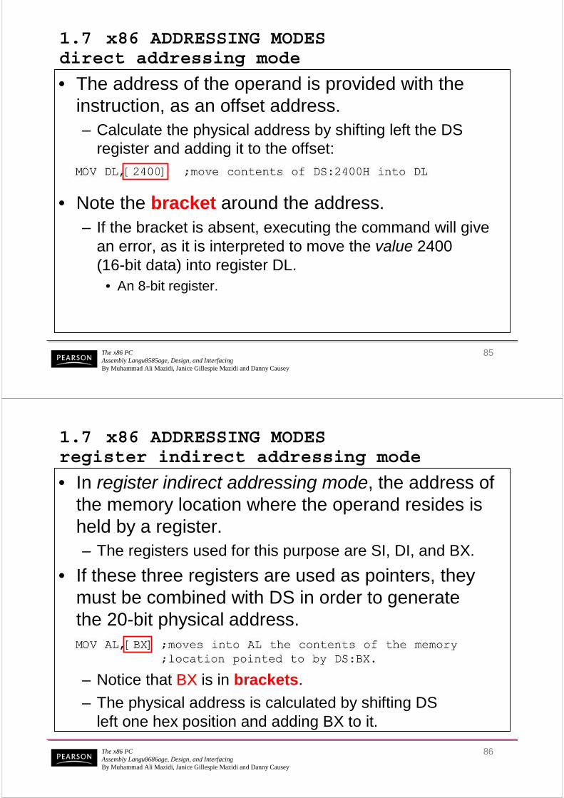
1.7 x86 ADDRESSING MODES direct addressing mode
• The address of the operand is provided with the instruction, as an offset address.– Calculate the physical address by shifting left the DS
register and adding it to the offset:
• Note the bracket around the address.– If the bracket is absent, executing the command will give
an error, as it is interpreted to move the value 2400 (16-bit data) into register DL.
• An 8-bit register.
The x86 PCAssembly Langu8686age, Design, and InterfacingBy Muhammad Ali Mazidi, Janice Gillespie Mazidi and Danny Causey
86
1.7 x86 ADDRESSING MODES register indirect addressing mode
• In register indirect addressing mode, the address of the memory location where the operand resides is held by a register.– The registers used for this purpose are SI, DI, and BX.
• If these three registers are used as pointers, they must be combined with DS in order to generatethe 20-bit physical address.
– Notice that BXBX is in brackets.
– The physical address is calculated by shifting DSleft one hex position and adding BX to it.

The x86 PCAssembly Langu8787age, Design, and InterfacingBy Muhammad Ali Mazidi, Janice Gillespie Mazidi and Danny Causey
87
1.7 x86 ADDRESSING MODES register indirect addressing mode
• The same rules apply when using register SI or DI.
• Example 1-16 shows 16-bit data.
The x86 PCAssembly Langu8888age, Design, and InterfacingBy Muhammad Ali Mazidi, Janice Gillespie Mazidi and Danny Causey
88
– Alternatives are "MOV CX,[BX+10]" or "MOV CX,10[BX]"
• Again the low address contents will go into CLand the high address contents into CH.
1.7 x86 ADDRESSING MODES based relative addressing mode
• In based relative addressing mode, base registers BX & BP, and a displacement value, are used to calculate the effective address.– Default segments used for the calculation of the
physical address (PA) are DS for BX and SS for BP.

The x86 PCAssembly Langu8989age, Design, and InterfacingBy Muhammad Ali Mazidi, Janice Gillespie Mazidi and Danny Causey
89
1.7 x86 ADDRESSING MODES based relative addressing mode
• In the case of the BP register:
– Alternatives are "MOV AL,[BP+5]" or "MOV AL,5[BP]".• BP+5 is called the effective address since the fifth byte from
the beginning of the offset BP is moved to register AL.
The x86 PCAssembly Langu9090age, Design, and InterfacingBy Muhammad Ali Mazidi, Janice Gillespie Mazidi and Danny Causey
90
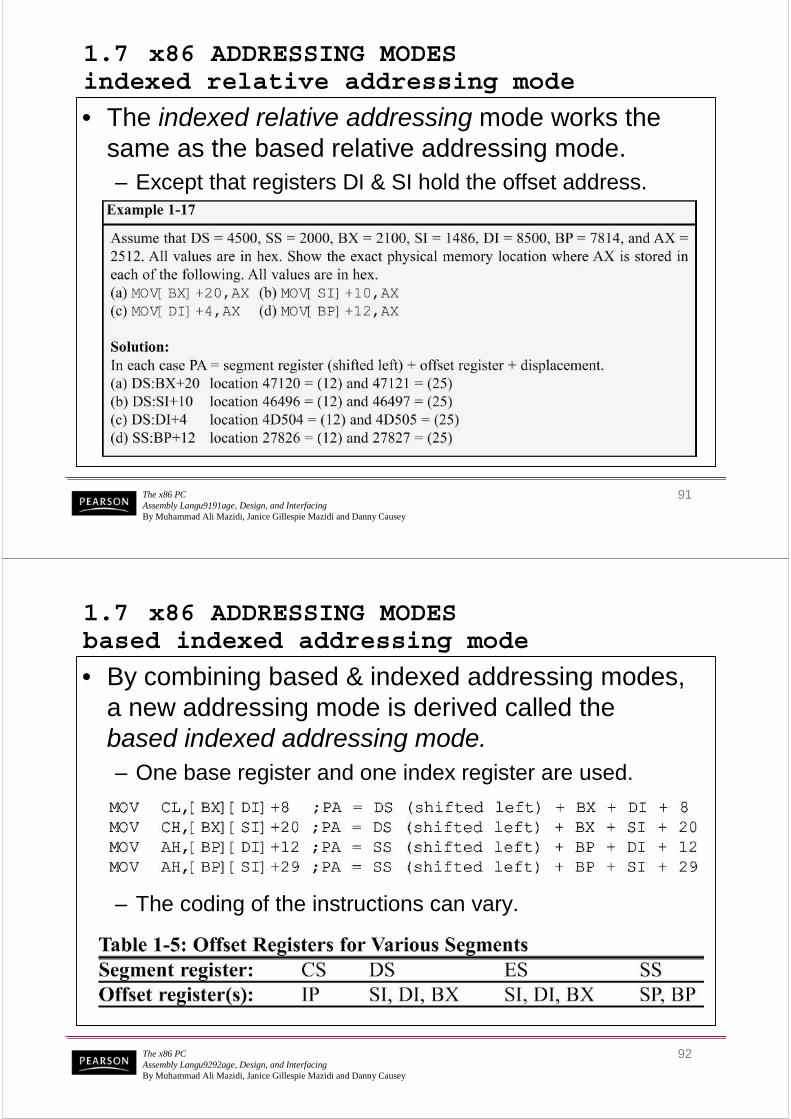
1.7 x86 ADDRESSING MODES indexed relative addressing mode
• The indexed relative addressing mode works the same as the based relative addressing mode.– Except that registers DI & SI hold the offset address.
The x86 PCAssembly Langu9191age, Design, and InterfacingBy Muhammad Ali Mazidi, Janice Gillespie Mazidi and Danny Causey
91
1.7 x86 ADDRESSING MODES indexed relative addressing mode
• The indexed relative addressing mode works the same as the based relative addressing mode.– Except that registers DI & SI hold the offset address.
The x86 PCAssembly Langu9292age, Design, and InterfacingBy Muhammad Ali Mazidi, Janice Gillespie Mazidi and Danny Causey
92
1.7 x86 ADDRESSING MODES based indexed addressing mode
• By combining based & indexed addressing modes, a new addressing mode is derived called the based indexed addressing mode.
– The coding of the instructions can vary.
– One base register and one index register are used.

The x86 PCAssembly Langu9393age, Design, and InterfacingBy Muhammad Ali Mazidi, Janice Gillespie Mazidi and Danny Causey
93
1.7 x86 ADDRESSING MODES segment overrides
• The x86 CPU allows the program to override the default segment and use any segment register.– In "MOV AL,[BX]", the physical address of the operand
to be moved into AL is DS:BX.• To override that default, specify the desired segment
in the instruction as "MOV AL,ES:[BX]"
The x86 PCAssembly Langu9494age, Design, and InterfacingBy Muhammad Ali Mazidi, Janice Gillespie Mazidi and Danny Causey
94
1.7 x86 ADDRESSING MODESsummary
The x86 PCAssembly Langu9595age, Design, and InterfacingBy Muhammad Ali Mazidi, Janice Gillespie Mazidi and Danny Causey
95
ENDS ; ONE
Dec Hex Bin
1 1 00000001