CGA S-1.1: Pressure Relief Device Standards - Law.Gov
56
By Authority Of THE UNITED STATES OF AMERICA Legally Binding Document By the Authority Vested By Part 5 of the United States Code § 552(a) and Part 1 of the Code of Regulations § 51 the attached document has been duly INCORPORATED BY REFERENCE and shall be considered legally binding upon all citizens and residents of the United States of America. HEED THIS NOTICE : Criminal penalties may apply for noncompliance. Official Incorporator : THE EXECUTIVE DIRECTOR OFFICE OF THE FEDERAL REGISTER WASHINGTON, D.C. Document Name: CFR Section(s): Standards Body: e
Transcript of CGA S-1.1: Pressure Relief Device Standards - Law.Gov
By Authority OfTHE UNITED STATES OF AMERICA
Legally Binding Document
By the Authority Vested By Part 5 of the United States Code § 552(a) and Part 1 of the Code of Regulations § 51 the attached document has been duly INCORPORATED BY REFERENCE and shall be considered legally binding upon all citizens and residents of the United States of America. HEED THIS NOTICE: Criminal penalties may apply for noncompliance.
Official Incorporator:THE EXECUTIVE DIRECTOROFFICE OF THE FEDERAL REGISTERWASHINGTON, D.C.
Document Name:
CFR Section(s):
Standards Body:
e
carl
Typewritten Text
Compressed Gas Association
carl
Typewritten Text
CGA S-1.1: Pressure Relief Device Standards
carl
Typewritten Text
49 CFR 173.301(c)


eGA 5-1.1-2005 (OBSOLETE)
PRESSURE RELIEF DEVICE STANDARDS
PART 1-CYLINDERS FOR
COMPRESSED GASES
TWELFTH EDITION
COMPRESSED GAS ASSOCIATION, INC. 4221 Walney Road, 5th Floor
Chantilly, VA 20151 Phone: 703-788-2700
Fax: 703-961-1831 E-mail: [email protected]

PLEASE NOTE:
The information contained in this document was obtained from sources believed to be reliable and is based on technical information and experience currently available from members of the Compressed Gas Association, Inc. and others. However, the Association or its members, jointly or severally, make no guarantee of the results and assume no liability or responsibility in connection with the information or suggestions herein contained. Moreover, it should not be assumed that every acceptable commodity grade, test or safety procedure or method, precaution, equipment or device is contained within, or that abnormal or unusual circumstances may not warrant or suggest further requirements or additional procedure.
This document is subject to periodic review, and users are cautioned to obtain the latest edition. The Association invites comments and suggestions for consideration. In connection with such review, any such comments or suggestions will be fully reviewed by the Association after giving the party, upon request, a reasonable opportunity to be heard. Proposed changes may be submitted via the Internet at our web site, www.cganet.com.
This document should not be confused with federal, state, provincial, or municipal specifications or regulations; insurance requirements; or national safety codes. While the Association recommends reference to or use of this document by government agencies and others, this document is purely voluntary and not binding.
A listing of all publications, audiovisual programs, safety and technical bulletins, and safety posters is available via the Internet at our website at www.cganet.com. For more information contact CGA at Phone: 703-788-2700, ext. 799. E-mail: [email protected].
NOTE-Technical changes from the previous edition are underlined.
NOTE-Appendices A and B (Normative) are requirements.
FOREWORD
Dockets 03-43a & 03-43b Cylinder Valve Committee
On April 16, 1981, the United States Department of Transportation promulgated new regulations to 49 CFR 173.34(d), which eliminated the need for pressure relief device approval by the Bureau of Explosives of the Association of American Railroads. It now becomes the responsibility of the individual manufacturer or shipper to conduct his own flow and/or fire tests on new pressure relief device combinations to show compliance with CGA S-1.1, CGA C-12, and CGA C-14 as applicable, and to retain test records of the compliance.
TWEFL TH EDITION: 2005 ELEVENTH EDITION: 2003
TENTH EDITION 2002 NINTH EDITION: 2001
© 2005 The Compressed Gas Association, Inc. All rights reserved. All materials contained in this work are protected by United States and international copyright laws. No part of this work may be reproduced or transmitted in any form or by any means, electronic or mechanical including photocopying, recording, or any information storage and retrieval system without permission in writing from The Compressed Gas Association, Inc. All requests for permission to reproduce material from this work should be directed to The Compressed Gas Association, Inc., 4221 Walney Road, Suite 500, Chantilly VA 20151. You may not alter or remove any trademark. copyright or other notice from this work.

CGA S-1.1-2005 ______ --"'C=o"'M:.:...P~R.::.ES"_'S""E""D:....:G~A""'S'_'A....:.S"_'S"_'O""'C""IA-'-'TC!.:IO""N""--"IN""C"". ___________ ,PAGE iii
Contents Page
Introduction ................................................................................................................................ . ...1
2 Definitions ..... ................... 2
3 Types of pressure relief devices...................... ......................................................... ...5 3.1 Type CG-1 ......................... ................. .......................................... .. ......................... 5 3.2 Type CG-2 ...... ........ ...... .......... .. ................ ...... .......... ............. ...... ................ .. ..................... 5 3.3 Type CG-3........ ...... ...... ................ .............. ...... ...... ........ .. ............................ 5 3.4 Type CGA .......... ..................... ............... ............. ................. .. ...................... 6 3.5 Type CG-5 ...... ...... ......... .. ........................................................................................... 6 3.6 Type CG-7.. .. ................................................................................................................... 6 3.7 Type CG-8.. ..... . ...................................................................................................................... 6 3.8 Type CG-9..................... .............................. ................ .. ............. 6 3.9 Type CG-10................................................. ............................... ....................................... .. .. 7 3.10 TypeCG-11 ..................................................................................................................................... 7 3.11 Type CG-12.. ..................... ................ ...................... ...7
4 Application requirements for pressure relief devices..... .. .... 7 4.1 General.......................... .................. ................7 4.2 CG-1 rupture disk devices............. ............. ............................. .. ............. 8 4.3 CG-7 pressure relief valves.. ............................................ ............. ................ .. ............ 9 4.4 CG-2, CG-3, and CG-9 fusible plug devices and CG-10 fusible trigger devices ....... .. ...... 9 4.5 CG-8 rupture disklpressure relief valve devices ...... ....... ............ ....... .. 10 4.6 Piping of pressure relief devices................ .................. .. .......................... 10 4.7 Relief devices for tubes - special considerations...... .. ............................. 10
5 Design and construction requirements for pressure relief devices......... .............. .. .................. 10 5.1 General requirements ......................................................... '" .................................................. 10 5.2 Material, design, and construction of a pressure relief device ...................................................... 11 5.3 CG-4 and CG-5 combination rupture-disklfusible-plug devices ................................................... 11 5.4 Flow capacity of pressure relief devices (nonliquefied gas)..... .............. ..11 5.5 Flow capacity of pressure relief devices (liquefied gas) .................. .12 5.6 Flow capacity of pressure relief valves (nonliquefied gas) ........... ....... ........ .. .. 12 5.7 Flow capacity of pressure relief valves (liquefied gas) ....... ................ . 13 5.8 Flow capacity for devices on CTC/DOT -4L and TC-4LM insulated cylinders ........ 13 5.9 Flow testing methods........... ............ ................. ............. . ........................ 16 5.10 Acetylene cylinders ............. ............. .................. .. ............ 17 5.11 CG-10 devices.................. .. .... 17
6 Manufacturer's tests....... ............ .. ... 17 6.1 Test of fusible alloy..... ...................... .................... ...17 6.2 Tests of CG-2, CG-3, and CG-9 fusible plugs and fusible trigger devices ..... .. 17 6.3 Tests of CG-1 rupture disk devices. ............... .. ... 19 6.4 Tests of CG-4 and CG-5 combination rupture-disklfusible-plug pressure relief devices ................. 20 6.5 Tests of CG-8 rupture disklpressure relief valve device .......... .......... .. .............. ........ .. ...... 21 6.6 Tests of CG-7 pressure relief valves ....................................................... . .......... 21 6.7 Testing of repaired pressure relief devices........ .................... ..................... .. ........ 22 6.8 Performance tests for CG-10 and CG-12 devices................... ...................................... .. ......... 22 6.9 Performance tests for CG-11 devices.. .. .......................................... 25 6.10 Performance tests for CG-12 devices ........................... ............. ............................ .. ............. 26
7 Identification requirements ... ............. 27
8 Maintenance requirements for pressure relief devices.............. ....................... .. ......................... 28 8.1 General practices ........................... ................. .. ............................................................ 28 8.2 Routine checks when filling cylinders ............. ........................... .. ... 29

PAGEiv __________ ----'C"-o""M"""-'PR'""E=-'s""s'-"E""D...;G~A..:.:S"_'A'__""'SS""'O"'"'C""I'_!AT.!..!I.:::O'-!N.>....!.'-'IN'-"Cc.:.... _______ CGAS-1.1-2005
9 Periodic replacement of pressure relief devices ........................................................................................ 29 9.1 CG-7 pressure relief valve.............. ................ ............................. . .................................... 29 9.2 CG-8 rupture disk/pressure relief valve .......................................................................................... 29 9.3 CG-11 and CG-12 pressure cycling relief valve... .... .. ...... ...... ........... . ..... 29
1 0 References ................................... . . ..... 29
11 Additional references ......................................................................................... . . .......................... 30
Tables
Table 1-Types of pressure relief devices .................. ................. . ................. 31 Table 2-FTSC numerical code for gas classification. ..... .... ........ ... ..... ..... . ....................... '" ......... 32 Table 3-Alphabeticallist of gases and devices assigned (see notes) ............... . ....................................... 33 Table 4-Temperature correction factors to 60 OF ........................................... ............. ............. . .... 42 Table 5-Basic orifice factors flange taps for flow in fe per minute .................... ......................... .43 Table 6-Values of G; and Gu for rated burst pressures of rupture disks for CTC/OOT-4L and
TC-4LM cylinders............................ ................................... ........................... . .............. 44 Table 7-ldentification requirements for pressure relief devices .................................................................... 47
Figure
Figure 1-Constant C for gas or vapor related to ratio of specific heats(k = Cp/Cv)
at 60 OF and 14.696 psia ............................................................ . . ............ 46
Appendices
Appendix A-Basis for sizing of pressure relief device (Normative) ..... '" .................................. . . ............. 48 Appendix B-Requalification procedures for CG-7 pressure relief valves (Normative) ................... . .50

CGA S-1.1-2005 _______ C~O!!!M!._'PR~E="S'"'S"=E""D~Ge!:A""SC!.A_"'s'"'s""O"'C.!!..IA!..!.T""IO""'N~IN!.:.C:.:... ___________ ,PAGE 1
1 Introduction
1.1
This standard represents the minimum requirements for pressure relief devices considered to be appropriate and adequate for use on cylinders having capacities of 1000 Ib (454 kg) of water or less. Refer also to Title 49 of the U.S. Code of Federal Regulations (49 CFR) 173.301(0 [1).1 This standard also applies to DOT-3AX, DOT-3AAX, and DOT-3T cylinders having capacities over 1000 Ib (454 kg) of water, and which comply with the design specifications and charging and maintenance regulations of the U.S. Department of Transportation (DOT) or the corresponding specifications and regulations of Transport Canada (TC) [1, 2). This standard also covers requirements for pressure relief devices for CTC/DOT-4L and TC-4LM insulated cylinders containing cryogenic liquids.
1.2
This standard includes Tables 1 to 6, which provide information pertaining to pressure relief devices. Table 1 contains information on the different types of pressure relief devices. Table 2 contains FTSC code classification for gases. Table 3 contains a listing of gases and their pressure relief device assignments. Table 4 contains temperature correction factors. Table 5 includes values for basic orifice factors flange taps for flow in cubic feet per minute. Table 6 contains values of Gi and Gu for rated burst pressure of rupture disks for CTCIDOT-4L and TC-4LM cylinders.
1.3
It is recognized that there are cylinders that conform to the specification requirements of DOT or TC, but are used in services beyond the jurisdiction of any of these authorities. In such cases, it is recommended that state, provinCial, local, or other authorities having jurisdiction over these cylinders be guided by this standard in determining adequate pressure relief device requirements provided that the cylinders are charged and maintained in accordance with DOT or TC regulations.
1.4
It is further recognized that there may be cylinders that are used in services beyond the jurisdiction of DOT or TC that do not conform to the specification requirements of either authority. It is recommended that the authorities having jurisdiction over such cylinders be guided by this standard in determining pressure relief device requirements, provided that such cylinders are considered by the authority as having a construction at least equal to the equivalent DOT or TC specification requirements, and further provided that the cylinder shall be charged and maintained in accordance with DOT or TC requirements.
1.5
For cylinders that come within the jurisdiction of state, provincial, and local regulatory authorities, the user should check for compliance with all such regulations. A number of states and cities have pressure vessel laws and regulations that include requirements for pressure relief devices. This standard has been prepared specifically for compressed gas cylinders, and the pressure relief devices may not be acceptable unless special permission is obtained from the authority having jurisdiction.
1.6
For newly constructed cylinders that come within the jurisdiction of DOT or TC, pressure relief devices shall comply with requirements of this standard. This publication is based on minimizing the number and optimizing the types of approved pressure relief devices specified for each specific gas. It does not prejudice the continued use of previously approved and installed devices unless stated otherwise in Table 3 and/or 49 CFR [1). However, if a pressure relief device is replaced, the new device shall meet the requirements of this standard.
It is the filler's responsibility to ensure that the pressure relief device is correct.
1 References are shown by bracketed numbers and are listed in order of appearance in the reference section.
PAGE 2. ___________ ""'C""'°"-'M!!..P-'-'R=E""ss""E"'D"-G"""-'A"'s~A""s""s""O..::C"_IA'_'_T_""IO"-'-N'-'-.!!IN.!.!C"-'. ________ CGA S-1.1-2005
1.7
For pressure relief device standards for bulk transport containers and stationary storage containers, see CGA S-1.2, Pressure Relief Device Standards-Part 2-Cargo and Portable Tanks for Compressed Gases, and CGA S-1.3, Pressure Relief Device Standards-Part 3-Stationary Storage Containers for Compressed Gases [3, 4].
2 Definitions
For the purpose of this standard, the following definitions apply.
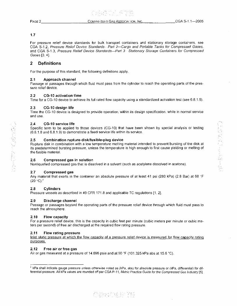
2.1 Approach channel Passage or passages through which fluid must pass from the cylinder to reach the operating parts of the pressure relief device.
2.2 CG-10 activation time Time for a CG-10 device to achieve its full rated flow capacity using a standardized activation test (see 6.8.1.5).
2.3 CG-10 design life Time the CG-10 device is designed to provide operation, within its design specification, while in normal service and use.
2.4 CG-10 service life Specific term to be applied to those devices (CG-10) that have been shown by special analysis or testing (6.8.1.8 and 6.8.1.9) to demonstrate a fixed service life within its service.
2.5 Combination rupture-disk/fusible-plug device Rupture disk in combination with a low temperature melting material intended to prevent bursting of the disk at its predetermined bursting pressure, unless the temperature is high enough to first cause yielding or melting of the fusible material.
2.6 Compressed gas in solution Nonliquefied compressed gas that is dissolved in a solvent (such as acetylene dissolved in acetone).
2.7 Compressed gas Any material that exerts in the container an absolute pressure of at least 41 psi (280 kPa) (2.8 Bar) at 68 OF (20°C).2
2.8 Cylinders Pressure vessels as described in 49 CFR 171.8 and applicable TC regulations [1, 2].
2.9 Discharge channel Passage or passages beyond the operating parts of the pressure relief device through which fluid must pass to reach the atmosphere.
2.10 Flow capacity For a pressure relief device, this is the capacity in cubic feet per minute (cubic meters per minute or cubic meters per second) of free air discharged at the required flow rating pressure.
2.11 Flow rating pressure Inlet static pressure at which the flow capacity of a pressure relief device is measured for flow capacity rating purposes.
2.12 Free air or free gas Air or gas measured at a pressure of 14.696 psia and at 60 of (101.325 kPa abs at 15.6 OC).
2 kPa shall indicate gauge pressure unless otherwise noted as (kPa, abs) for absolute pressure or (kPa, differential) for differential pressure. All kPa values are rounded off per CGA P-11, Metric Practice Guide for the Compressed Gas Industry [5].

CGA S-1.1-2005 _______ C=O!!!M"-P""RE""S""S""E""D->G""A.",S:...:,A-"s""s"'O""C"'-IA"".T""IO",-N!J..' .!.!.IN""C,-,-. ___________ PAGE 3
2.13 Fusible plug device Nonreclosing pressure relief device designed to function by the yielding or melting of a plug of fusible material at a suitable temperature.
2.14 Fusible trigger device Nonreclosing pressure relief device designed to function by activation of a trigger incorporating a fusible material that yields, melts, or is otherwise activated by heat.
NOTE-The trigger activates a mechanism that permits the release of gas.
2.15 Hazard zone A Material with a toxicity LCso less than or equal to 200 ppm.
2.16 Hazard zone B Material with a toxicity LCso greater than 200 ppm and less than or equal to 1000 ppm.
2.17 Hazard zone C Material with a toxicity LCso greater than 1000 ppm and less than or equal to 3000 ppm.
2.18 Hazard zone 0 Material with a toxicity LCso greater than 3000 ppm and less than or equal to 5000 ppm.
2.19 Lethal concentration fifty (LC50)
Concentration of a substance in air, exposure to which for a specified length of time is expected to cause the death of 50% of the entire defined experimental animal population.
2.20 Liquefied compressed gas Gas that under the charged pressure is partially liquid at a temperature of 70 of (21.1 °C).
2.21 Metal hydride Compound consisting of a metal alloy and hydrogen.
NOTE-As it pertains to this document, these compounds are used in a metal hydride system where the hydrogen absorbs and desorbs from the metal alloy.
2.22 Metal hydride system Group of components assembled as a package to contain metal-hydrogen compound(s) for which there exists an equilibrium condition where the metal alloy(s) hydrogen gas and the metal-hydrogen compound(s) co-exist.
NOTE-Changes in pressure, temperature, and/or electrical potential shifts the equilibrium favoring the formation or decomposition of the metal-hydrogen compound(s) with respect to the metal alloy(s) and hydrogen gas.
2.23 Nonliquefied compressed gas Gas other than a gas in solution that under the charging pressure is entirely gaseous at a temperature of 70 of (21.1 OC).
2.24 Pressure control valve As used on a cryogenic cylinder, device that vents only to maintain the proper working pressure of the cylinder under normal working conditions.
2.25 Pressure opening Orifice against which the rupture disk functions.
2.26 Pressure relief device Pressure and/or temperature-activated device used to prevent the pressure in a normally charged cylinder from rising above a predetermined maximum, thereby preventing rupture of the cylinder when subjected to a standard fire test as required by 49 CFR 173.34(d) or 73.34(d) of the TC regulations [1, 2).
NOTE-The term "pressure relief device" is synonymous with "safety relief device" as used by DOT or TC regulations [1, 2]. See Section 5 for further explanation of these devices.

PAGE 4 ___________ C=O.!!:M"--P.!..!R=:ES"'S"-'E""D'-..G::::!..!A"'-S-'-A""s""s"'-O"'-C"-'IA'-!.T'-'=IO"-'N"--'-'-IN.",C"'-. ________ CGA S-1.1-2005
2.27 Pressure relief valve Type of pressure relief device designed to relieve excessive pressure and to reciose and reseal to prevent further flow of gas or fluid from the cylinder.
2.28 Projecting-type relief device Pressure relief device in which the body of the device has been extended to provide for exhaust ports that divert the exhaust fluid in a plane parallel to the longitudinal axis of the cylinder.
2.29 Psi, psig, or psia "Psi" is interpreted as pounds per square inch, "psig" is pounds per square inch gauge, and "psia" refers to absolute pressure that is based on a zero reference point-the perfect vacuum.
2.30 Rated burst pressure Maximum pressure for which a rupture disk is designed to rupture at one specific temperature within the range of 60 OF to 160 OF (15.6 °c to 71.1 °C) when in contact with the pressure opening for which it was designed when tested as required in 6.3.
2.31 Cryogenic liquid Liquid with a normal boiling point below -130 OF (-90°C) at 1 atm pressure absolute.
2.32 Resealing pressure Value of decreasing pressure at which leakage ceases to appear through a water seal of not over 4-in (102-mm) water column or other equivalent leakage detection method on the outlet of the pressure relief valve or pressure control valve, after the device has been sublected to a pressure greater than the start-to-discharge pressure but below a pressure which allows a much faster rate of release.
2.33 Reseating pressure Value of decreasing pressure at which leakage ceases to appear through a water seal of not over 4-in (102-mm) water column or other equivalent leakage detection method on the outlet of the pressure relief valve or pressure control valve, after the device has been subjected to the flow rating pressure.
2.34 Room temperature Any temperature within the range of 60 OF to 80 OF (15.6 °c to 26. rC).
2.35 Rupture disk Operating part of a pressure relief device that when installed in the device is designed to burst at a predetermined pressure to permit the discharge of fluid.
NOTE-Such disks, usually metal, are generally of flat, preformed, reinforced, or grooved types.
2.36 Rupture disk device Nonreclosing pressure relief device actuated by static pressure and designed to function by the bursting of a pressure-containing disk.
2.37 Set pressure Pressure at which the manufacturer of a pressure relief valve sets the device to meet the requirements of the start-to-discharge pressure range (see 4.3.2).
2.38 Start-to-discharge pressure For a pressure relief valve or pressure control valve, this is the pressure at which the first bubble appears through a water seal of not over 4-in (102-mm) water column or other equivalent leakage detection method from the outlet of the pressure relief valve or pressure control valve (see 6.6).
2.39 Test pressure of the cylinder Minimum pressure at which a cylinder shall be tested as prescribed in the specifications for compressed gas cylinders by DOT or TC.
CGAS-1.1-2005 _______ ""'C""'O!!,!M.:...P""'RE"'S""S"'E""D...::G""A""S'-!,A-"s""s""'o'"C""IA"-'.T""'IO""N:!J...""IN""'C'-'-. ___________ PAGE5
2.40 Trailer tubes DOTITC cylinders horizontally mounted to a chassis for over-the-road transportation.
NOTE-This includes DOT cylinders horizontally mounted on modular units that can be transported over the road.
2.40.1 Front end of a tube trailer End used for attaching the tractor, which would move the trailer.
2.40.2 Tubes Cylinders over 12 ft long.
2.40.3 Tubes, jumbo Tubes with a diameter 18 in (45.7 cm) or greater.
2.40.4 Tubes, small Tubes with a diameter less than 18 in (45.7 cm).
2.41 Tube trailer internal relief device Relief device configuration used on tubes wherein the components of activation are contained within the tube or end plug of the tube.
2.42 Yield temperature For a fusible plug, temperature at which the fusible material becomes sufficiently soft to extrude from its holder to permit the discharge of fluid when tested in accordance with 6.2.
3 Types of pressure relief devices
Types of pressure relief devices are designated as follows:
3.1 Type CG-1
A rupture disk device (see 2.35),
3.1.1 Limitations
Since this is a pressure-operated device designed to release the entire contents of the container, there is no way to prevent the complete release of the contents, either as a result of normal functioning or premature rupture of the device.
3.2 Type CG-2
A fusible plug using a fusible alloy with a yield temperature not over 170 OF (76.7 0c) or less than 157 OF (69.4 0c) Nominal yield temperature: 165 OF (73.9 °e).
3.2.1 Limitations
Since this is a thermally operated device, it does not protect against overpressure from improper charging practices. This device releases the entire lading of the container when it functions, and is limited to use on cylinders of 500 psig (3450 kPa) service pressure or less. This device may be used in higher service pressure cylinders provided that the product pressure does not exceed 500 psig (3450 kPa) at 68 OF (20°C) and the device type is mandated by this standard or TC regulations.
3.3 Type CG-3
A fusible plug using a fusible alloy with a yield temperature not over 224 OF (106.7 °C) or less than 208 OF (97.8 °C). Nominal yield temperature: 212 OF (100°C).
3.3.1 Limitations
Same as for CG-2 (see 3.2.1).
3.4 Type CG-4
A combination rupture-disklfusible-plug device using a fusible alloy with a yield temperature not over 170 of (76.7 °C) or less than 157 of (69.4 0G). Nominal yield temperature: 165 of (73.9 °C).
3.4.1 Limitations
Since this device is a combination device, it requires both excessive pressure and temperature to cause it to operate. This device will not function due to excessive pressure unless the fuse metal is melted out first. Such a combination device cannot prevent an improperly filled (overfilled) cylinder from rupturing due to hydrostatic pressure at room temperature or any temperature below the melting temperature of the fusible metal, as will devices that contain only a rupture disk (CG-1). There is no way to prevent the complete release of the contents when this device functions.
3.5 Type CG-5
A combination rupture-disk/fusible-plug device, using a fusible alloy with a yield temperature not over 224 OF (106.7 0G) or less than 20S OF (97.S °C). Nominal yield temperature: 212 OF (100°C).
3.5.1 Limitations
Same as for CG-4 (see 3.4.1).
3.6 Type CG-7
A pressure relief valve (see 2.27).
3.6.1 Limitations
This device is intended to limit (determined by the set pressure of this device) the maximum pressure in a container. This device does not protect against rupture of the container when the application of heat weakens the container to the point where its rupture pressure is less than the operating pressure of the device. It is limited to use on cylinders with charging pressures that do not exceed 500 psig (3450 kPa).
3.7 Type CG-S
A rupture disk device followed by and in series with a pressure relief valve. The piping connecting the rupture disk and pressure relief valve shall be equipped with a senSing device to indicate pressure. This system shall be designed and constructed so the relieving capacity prescribed in 5.5 is achieved and the operation of the relief valve is not impeded.
3.7.1 Limitations
This device is a pressure-actuated device. It is intended to maximize containment of the lading following release of temporary overpressure by closure of the relief valve. Prior to release, it is less likely to exhibit leakage due to the hermetic seal of the rupture disk device. It is not intended for applications in which rapid opening is required due solely to extreme rise in surrounding temperature. It is not designed to protect the cylinder from rupture during exposure to a fire.
3.S Type CG-9
A fusible plug for use at cylinder service pressures above 500 psig (3450 kPa) using a fusible alloy with a yield temperature not over 224 OF (106.7 °C) or less than 20B OF (97.B °C). Nominal yield temperature: 217 OF (102.7 °C).
3.8.1 Limitations
Since this is a thermally operated device, it does not protect against overpressure from improper charging practices. This device releases the entire lading of the container when it functions, and is limited to use on cylinders with service pressures that do not exceed 6000 psig (41 400 kPa).
CGA S-1.1-2005. ______ ~C~O~MC!.!:P~Rc!:;ES~S~E~D~G~A~S~A:!>s~s~o~C!!C1Ac.!..!TI~O:!..!N......!I.!..!N~C'_. __________ PAGE 7
3.9 Type CG-10
A fusible trigger device with an activation time of less than 90 seconds at a fill pressure within the rated pressure range marked on the device, but not to exceed 13 100 psig (90300 kPa). A CG-10 device shall be a fixed service life device with a design life not less than 20 years.
3.9.1 Limitations
Since this is a thermally operated device, it does not protect against overpressure from improper charging practices. This device releases the entire lading of the container when it functions. It is limited to use on cylinders whose service pressure is within the rated pressure range marked on the device, but not to exceed 13 100 psig (90 300 kPa).
3.10 Type CG-11
A pressure cycling relief valve capable of activating and reseating/resealing multiple times.
3.10.1 Limitations
This device is intended to limit (determined by the set pressure of this device) the maximum pressure in a container. This device does not protect against rupture of the container when the application of heat weakens the container to the point where its rupture pressure is less than the operating pressure of the device. The design life (a theoretical number expressed in years that the device is expected to perform its intended function) of the device shall be a minimum of 5 years. The device shall be removed from service upon the expiration of the design life but no more than 10 years from the date of manufacture.
3.11 Type CG-12
A single pressure relief device combining the general characteristics of a fusible trigger device and a pressure cycling relief valve. The device can be activated by either temperature or pressure.
3.11.1 Limitations
The operation of the fusible trigger releases the entire lading of the container. It is limited to use on cylinders with service pressures that are within the rated pressure range marked on the device but not to exceed 13 100 psig (90 300 kPa).
4 Application requirements for pressure relief devices
4.1 General
4.1.1
Each cylinder charged with compressed gas, unless excepted in 4.1.1.1, shall be equipped with one or more pressure relief devices complying with the application assignments of Table 3 and the other requirements of this standard. Relief devices shall be suitably checked for leaks before shipment. Cylinders that are found to be equipped with leaking or faulty relief devices shall not be shipped until proper repair or replacement is made.
4.1.1.1
Pressure relief devices for gases or liquids meeting the DOT definition of Hazard Zone A and other gases or liquids as designated by the DOT or TC are prohibited.
4.1.2
The design, material, and location of pressure relief devices shall be suitable for the intended service. Consideration shall be given in the design and application of pressure relief devices to the effect of the resultant thrust when the device functions.

PAGE 8 ___________ "'C""O:!!.M!!.,.P.!..!R=.ES""S""E""D<-G""'-!A"'-S.!-A!-"s""s""O""C!!..IA:..:.T""1o"'N'-'-!!IN"-'C"-. ________ CGA S-1.1-2005
4.1.3
When the devices are used at both ends of a cylinder or tube the flow capacity of each device may be combined to meet the minimum flow capacity requirement. In no case shall the flow capacity at one end of the tube be less than 50%.
4.1.4
When cylinders are required to be equipped with pressure relief devices at one end only, the flow capacity of individual pressure relief devices may be combined to meet the minimum flow capacity requirement. This provision is limited to CG-1 and CG-7 pressure relief devices.
4.1.5
A CG-9 device, where authorized in Table 3, may be used in parallel with either a CG-1 device or CG-7 device. Where either of these combinations is used, the minimum required flow capacity shall be satisfied by the CG-1 or CG-7 device, whichever may be the case.
4.1.6
When cylinders are required to be equipped with a CG-11 or CG-12 device the minimum flow capacity requirement may be satisfied by using multiple CG-11 or multiple CG-12 devices in parallel.
4.1.7
F or metal hydride systems with a CG-10 device a CG-11 device is also required whenever the thermodynamics of the metal hydride are such that the pressure in the cylinder exceeds the test pressure of the cylinder at a temperature less than the activation temperature of the CG-1 0 device. A CG-12 device can be used in place of the CG-10/CG-11 combination.
4.2 CG-1 rupture disk devices
When a rupture disk device is used as a pressure relief device on a compressed gas cylinder, the rated bursting pressure of the disk when tested at the specified design temperature within the range of 60 OF to 160 OF (15.6 °C to 71.1 0c) in accordance with 6.3 shall not exceed the minimum required test pressure of the cylinder with which the disk is used, except as follows:
4.2.1
For DOT-3E or TC-3E cylinders, the rated bursting pressure of the disk shall not exceed 4500 psig (31 030 kPa).
4.2.2
For DOT-39 and TC-39M cylinders, the burst pressure of the disk shall not exceed 80% of the minimum required cylinder burst pressure and shall not be less than 105% of the cylinder test pressure. -
4.2.3
Except as provided in 4.2.1 and 4.2.2, for rupture disks designed to have a rated burst pressure at a specific temperature greater than 60 of (15.6 °C) but not exceeding 160 of (71.1 °C), the corresponding rated burst pressure at room temperature shall not exceed 110% of the minimum required test pressure of the cylinder with which the disk is used.
4.2.4
Rupture disk device settings authorized for low pressure cylinders for a particular gas may be used on higher pressure cylinders for the same gas provided that the product fill density and pressurization level are the same as specified for the low pressure cylinder.
CGA S-1.1-2005 _______ C=o!!!M!...PR~E=_'S""S"=E""D...::G=::.A:!::S:..!.A~s""s~O~C~IA:!..!.T~IO~N!..1.' .!!.IN""C~. ___________ PAGE 9
4.3 CG-7 pressure relief valves
4.3.1 Flow rating pressure
The flow rating pressure for pressure relief valves shall be the minimum test pressure of the intended low pressure cylinder (maximum 500 psig [3450 kPa] service pressure). For DOT-39 and TC-39M cylinders, the flow rating pressure for pressure relief valves shall be 80% of the minimum cylinder burst pressure.
A pressure relief valve may incorporate a fusible element to relieve the total contents at a predetermined temperature. Where both a pressure relief valve and a fusible element are allowed, the minimum required flow capacity shall be satisfied by the pressure relief valve.
4,3.2 Set pressure
Pressure relief valves shall have a start-to-discharge pressure not less than 75% or more than 100% of the minimum test pressure of the cylinder.
For liquefied gases, pressure relief valve settings authorized for low pressure cylinders for a particular gas shall be used on high pressure (over 500 psi service pressure) cylinders for the same gas.
Pressure relief valves for DOT-39 and TC-39M cylinders shall have a start-to-discharge pressure not less than 105% of the cylinder test pressure or more than 80% of the minimum required cylinder burst pressure. The reseating pressure, after the start-to-discharge pressure has been determined, shall not be less than 80% of the cylinder test pressure.
The blowdown (reseating) pressure for pressure relief valves shall be determined after the start-to-discharge pressure has been established. The blowdown (reseating) pressure shall not be less than the pressure in a normally charged cylinder at 130 OF (54.4 0c).
4.4 CG-2, CG-3, and CG-9 fusible plug devices and CG-10 fusible trigger devices
4,4.1
CG-2 and CG-3 devices may be used on cylinders whose marked service pressures do not exceed 500 psig (3450 kPa). These devices may be used on higher service pressure cylinders provided that the product pressure does not exceed 500 psig (3450 kPa) at 68 OF (20°C) and the device type is mandated by this standard or TC regulations.
4,4.2
CG-9 devices may be used on cylinders whose marked service pressures do not exceed 6000 psia (41 400 kPa). CG-10 devices are permitted to be used on cylinders whose marked service pressures do not exceed 13 100 psig (90300 kPa).
4,4.3
No CG-1 0 device is permitted to eject internal components outside the body of the device.
4.4.4
CG-10 devices shall only be installed into service where normal exposure temperatures are from -40 OF to 180 OF (-40 °C and 82°C).
PAGE 1 O __________ ..:::C""o:.:.:.M!!..P~R.=:ES""S"_'E="Dc..::G""A'""S"_'A'_"s""s"_"O"_"C'""IA_'_'TC!.:IO""N.!J.,-"IN""C""'. _______ CGA S-1.1-2005
4.5 CG-8 rupture disk/pressure relief valve devices
A CG-8 device may be used in parallel with one or more rupture-disk/fusible-plug devices as auxiliary overpressure protection. The CG-8 device shall be sized in accordance with 5.5. The set pressure of this device is the greater of:
the rated burst pressure of the disk at 60 of (15.6 °C); or
the set pressure of the relief valve (and shall be not less than 0.75 times the cylinder test pressure).
However, the set pressure shall not exceed the cylinder test pressure. The CG-8 system shall discharge within the control cabinet of the trailer or to a location that will not impinge on personnel.
The rupture disk portion of a rupture disk/pressure relief valve device (CG-8) shall have a rated burst pressure between 0.75 and 1 times the cylinder test pressure at 60 of (15.6 °C).
4.6 Piping of pressure relief devices
When fittings and piping are used on either the approach channel (upstream) or discharge channel (downstream) side or both sides of a pressure relief device or devices, the fittings and piping shall be designed so that the flow capacity of the pressure relief device shall not be reduced below the capacity required for the cylinder on which the pressure relief device assembly is installed or to the extent that the operation of the device could be impaired. Fittings, piping, and the method of attachment shall be designed to withstand normal handling and the pressures developed when the device or devices function.
A shut-off valve shall not be installed between the pressure relief devices and the cylinder or in the discharge channel.
4.7 Relief devices for tubes-special considerations
All tube trailers or jumbo tube trailers carrying gases with an FTSC code fire potential of 2, 3, or 5 shall be equipped with vent lines pointing upwards and attached to relief devices on the front end of the tubes when said tubes are equipped with relief devices.
All tube trailers (jumbo and small) that have relief devices shall have those devices either be "internal pressure relief devices" or be protected from damage by an external structure or shield provided the structure or shield:
is capable of withstanding a 2g impact load (twice the gross trailer weight) without any leakage from the relief device;
is capable of withstanding a 2g impact load (twice the gross trailer weight) acting in any direction with a minimum safety factor of three based on the actual tensile strength of the material used;
does not compromise the tube's mechanical integrity;
does not create a tube puncture hazard; and
is retained with the tube in the event of a tube dislocation from the tube trailer.
5 Design and construction requirements for pressure relief devices
5.1 General requirements
The design, material, and location of pressure relief devices shall be suitable for the intended service. In the design and application of pressure relief devices, consideration shall be given to the effect of the resultant thrust when the device functions.
To reduce the effect of the resultant thrust when the pressure relief device functions, a projected-type pressure relief device that diverts the exhaust fluid in a plane parallel to the longitudinal axis of the cylinder should be considered. This diversion of the exhaust fluid balances the thrust forces and virtually eliminates cylinders tipping over or being dangerously propelled when the pressure relief device functions.

CGA S-1.1-2005 _______ =C=o=M.:....P'-"RE=S=S=E=O--=G"'-A-"'S:..:.A...:..:s=s'-"o"'cc.::..1A.!..!T-'-'IO"_!.N~IN.;.;,C"_!.. __________ PAGE 11
When used with liquefied flammable ladings, pressure relief devices and valves shall be in direct contact (communication) with the vapor space of the cylinder when in normal use. Normal use is defined as the position of the cylinder during withdrawal of its contents.
WARNING: Pressure relief devices may not prevent rupture of a cylinder under all conditions of fire exposure. When the heat transferred to the cylinder is localized, intense, and remote to the relief device or when the fire builds rapidly such as in an explosion and is of very high intensity, the cylinder can weaken sufficiently to rupture before the relief device operates or while it is operating.
5.2 Material, design, and construction of a pressure relief device
The design and selection of material and construction of a pressure relief device shall minimize the effects of the environment in its intended use. However, under certain conditions and over time, the performance of a CG-7 device can vary from its initial start-to-discharge pressure (see 6.6.1). Periodic maintenance of pressure relief devices is required to ensure their long-term performance (see Section 8).
Improper maintenance and/or abuse adversely affects the proper functioning of these devices (see Section 8).
5.3 CG-4 and CG-5 combination rupture-disk/fusible-plug devices
In combination rupture-disk/fusible-plug devices, the fusible metal shall be on the discharge side of the rupture disk. The fusible metal shall not be used in lieu of a gasket to seal the disk against leakage around the edges. Gaskets shall be of a material that will not deteriorate rapidly at the maximum temperature range specified for the fusible metal.
5.4 Flow capacity of pressure relief devices (non liquefied gas)
For uninsulated cylinders for nonliquefied gas, the minimum required flow capacity of pressure relief devices, except pressure relief valves, shall be calculated using the following formula. (For pressure relief valves, see 5.6 and 5.7.)
5.4.1 U.S. customary units
Where:
Qa Flow capacity at 100 psi a test pressure in fe per minute of free air
We Water capacity of the cylinder in pounds, but not less than 25 Ib
NOTE-The above formula expresses flow capacity requirements equal to 70% of that which will discharge through a perfect orifice having a 0.00012 in cross-section area for each pound of water capacity of the cylinder.
5.4.2 Metric (51) units
Where:
Qa = Flow capacity at 690 kPa (abs) in m3 per minute of free air
We Water capacity of the cylinder in kilograms, but not less than 11.3 kg
NOTE-The above formula expresses flow capacity requirements equal to 70% of that which will discharge through a perfect orifice having a 0.171 mm2 cross-section area for each kilogram of water capacity of the cylinder.
PAGE 12 __________ -"'C""O"-'M.::..P.:..:R""E""'-SS""E'=-'O"--'='G;:,.;A""S..:..A-"'s""s""O-"'C.::..IA!..!.T'-"1o"'-N'"->...'-'IN.!.:C""'. ________ CGA S-1.1-2005
5.4.3 Fire test
Fire testing shall be conducted when the flow capacity of a pressure relief device is sized less than required by the formula in this standard. If a fire test is required, it shall be performed in accordance with CGA C-14, Procedures for Fire Testing of DOT Cylinder Pressure Relief Device Systems or CGA C-12 Qualification Procedure for Acetylene CY/inder Design (Section 5.8) as applicable [6 7J.
5.5 Flow capacity of pressure relief devices (liquefied gas)
For uninsulated cylinders for liquefied gas, the minimum required flow capacity of pressure relief devices, except pressure relief valves, shall be two times that required by the formula in 5.4.1 or 5.4.2. (For pressure relief valves, see 5.6 and 5.7; for CG-8 devices, refer to 5.5.1 and 5.5.2.)
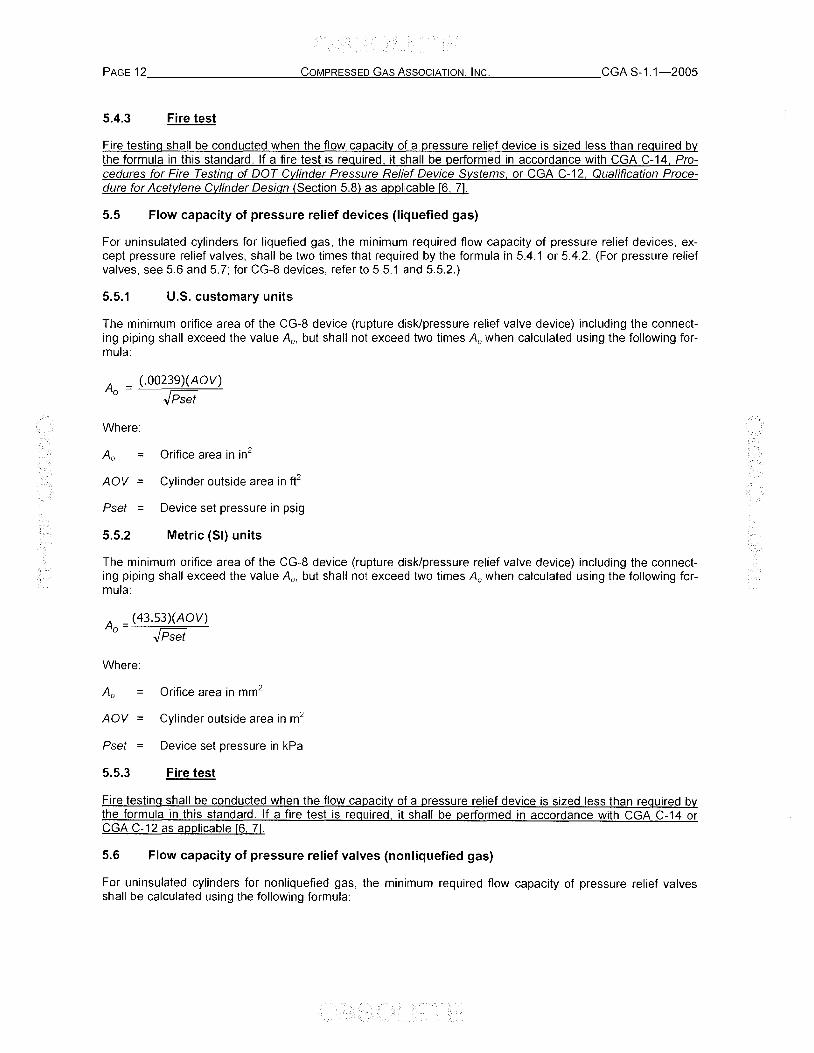
5.5.1 U.S. customary units
The minimum orifice area of the CG-8 device (rupture disk/pressure relief valve device) including the connecting piping shall exceed the value Ao, but shall not exceed two times Ao when calculated using the following formula:
A = (.00239)(AOV) o .JPset
Where:
Ao Orifice area in in2
AOV Cylinder outside area in fe
Pset Device set pressure in psig
5.5.2 Metric (51) units
The minimum orifice area of the CG-8 device (rupture disk/pressure relief valve device) including the connecting piping shall exceed the value Ao, but shall not exceed two times Ao when calculated using the following formula:
A - (43,53)(AOV) 0- .JPset
Where:
Ao Orifice area in mm2
AOV Cylinder outside area in m2
Pset Device set pressure in kPa
5.5.3 Fire test
Fire testing shall be conducted when the flow capacity of a pressure relief device is sized less than required by the formula in this standard. If a fire test is required, it shall be performed in accordance with CGA C-14 or CGA C-12 as applicable [6, 7J.
5.6 Flow capacity of pressure relief valves (nonliquefied gas)
For uninsulated cylinders for nonliquefied gas, the minimum required flow capacity of pressure relief valves shall be calculated using the following formula:

eGA S-1.1-2005 _______ e""'-"'o!!!M'-PR'-"E'=-'s''''s'-'=E""'D...::G~A_"'s'_'_A_"s""s"'O'_"'CC!!.IA.!..!.T.!-"IO",-N!J..! .!!.IN~C,-,-. __________ PAGE 13
5.6.1 U.S. customary units
Where:
Qa Flow capacity in fe per minute of free air
P Flow rating pressure in psia
We Water capacity of the cylinder in pounds, but not less than 12.5 Ib
5.6.2 Metric (51) units
Where:
Q a Flow capacity in m3 per minute of free air
P Flow rating pressure in kPa (abs)
We Water capacity of the cylinder in kilograms, but not less than 5.7 kg
5.7 Flow capacity of pressure relief valves (liquefied gas)
For uninsulated cylinders for liquefied gas, the minimum required flow capacity of pressure relief valves shall be two times that required by the formulas in 5.6.1 or 5.6.2.
5.8 Flow capacity for devices on CTCIDOT-4L and TC-4LM insulated cylinders
For specification eTe/DOT-4L and TC-4LM insulated cylinders containing cryogenic liquids listed in Table 3, the following requirements apply:
5.8.1
If all materials comprising a representative sample of the insulation system remain completely in place when subjected to 1200 of (649 °e), the U value shall be as defined as follows and the minimum required flow capacity of the pressure relief device(s) shall be calculated using the following formula:
Where:
U Total thermal conductance of cylinder insulating material in Btu/(hr • ff • OF) (or the metric equivalent kJ/(h • m2
• 0C)) when saturated with gaseous lading or air at atmospheric pressure, whichever is greater. The value of U is determined at 100 of (37.8 0c) except when 5.8.2.2 or 5.8.2.3 applies. (U is equal to the thermal conductivity of the insulation divided by the thickness of the insulation.)
A Total outside surface area of the cylinder in ft2 (m2)
Qa Flow capacity in ft3 per minute (m3 per hour) of free air at the rated burst pressure of the rupture disk
G; Gas factor for insulated containers obtained from Table 6 for the gas involved
NOTE-Be careful to select from the proper units column, U.S. Customary or Metric.

PAGE 14 __________ -"'C""OO!!M"-P-'-'R""E-"'-SS""E""D:.....;::Go:..;A:.><S.!,.A"'s""s"'O-"C.::..IA.:..:.T.!-'1o"-!.N"'-'--"IN..:..:C"". ________ CGA S-1.1-2005
CAUTION: The formula Qa 0.82
= GjUA is sensitive to units of G; and A. Values provided by the formulas or
tables for G; are not convertible to the other unit directly since the formula or table in each unit contains different coefficients for time and area.
5.8.2
If any material comprising a representative sample of the insulation system deteriorates or remains only partly in place when subjected to 1200 OF (649°C), one of the following procedures shall be used to determine the minimum flow capacity requirement of the pressure relief device(s):
5.8.2.1
Use the formula for uninsulated cylinders:
Where:
Q a and A are as defined in 5.8.1.
Gu = Gas factor for uninsulated containers obtained from Table 6 for the gas involved. (Be careful to select from the proper units column, U.S. Customary or Metric.)
Q G A0 82 CAUTION: The formula a = U is sensitive to units of Gu and A. Values provided by the formulas or
tables for Gu are not convertible to the other unit directly as the formula or table in each unit contains different coefficients for time and area.
5.8.2.2
Determine the total thermal conductance (U) for a representative sample of the insulation system with a 1200 OF (649°C) external test environment. This value of U shall then be used in the formula in 5.8.1 to determine the minimum required flow capacity of the pressure relief device(s). The value of U shall be determined with the insulation saturated with gaseous lading or air at atmospheric pressure, whichever provides the greater thermal conductance.
5.8.2.3
If the insulation system is equipped with a jacket that remains in place during fire conditions, the thermal conductance U shall be determined with no insulation and a 1200 OF (649°C) external test environment. The value of U shall be determined with gaseous lading or air at atmospheric pressure in the space between the jacket and cylinder, whichever provides the greater thermal conductance. This value of U shall then be used in the formula in 5.8.1 to determine the minimum required flow capacity of the pressure relief device(s).
5.8.2.4
An alternative procedure may be used to qualify a composite insulation, which consists of layers of several different insulations over the entire cylinder, by exposing a sample of the composite insulation to a temperature of 1600 OF (871°C) for 30 minutes, and using only the layer(s) of the insulation that is unaffected in determining the value of U to be used in the formula in 5.8.1 to calculate the minimum required flow capacity of the pressure relief device(s). Such high temperature insulation shall be kept in place by an appropriate retainer (as required by the insulation) that will remain serviceable at 1600 OF (871°C).
5.8.2.5
Perform a fire test on a full-scale cylinder, the results of which demonstrate that the pressure relief devices are capable of preventing rupture of the normally charged cylinder. See CGA C-14 for details on apparatus and procedures for the fire testing of DOT cylinder/pressure relief device systems [6].
5.8.3
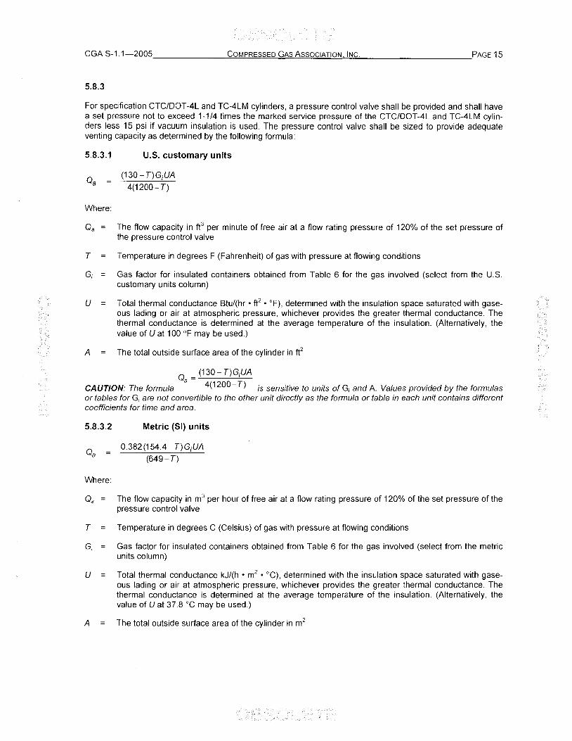
For specification CTC/OOT-4L and TC-4LM cylinders, a pressure control valve shall be provided and shall have a set pressure not to exceed 1-1/4 times the marked service pressure of the CTC/OOT-4L and TC-4LM cylinders less 15 psi if vacuum insulation is used. The pressure control valve shall be sized to provide adequate venting capacity as determined by the following formula:
5.8.3.1
Where:
u.s. customary units
(130 - T)GiUA
4(1200- T)
Q a = The flow capacity in ft3 per minute of free air at a flow rating pressure of 120% of the set pressure of the pressure control valve
T Temperature in degrees F (Fahrenheit) of gas with pressure at flowing conditions
G; Gas factor for insulated containers obtained from Table 6 for the gas involved (select from the U.S. customary units column)
U Total thermal conductance Btu/(hr • ft2 • OF), determined with the insulation space saturated with gaseous lading or air at atmospheric pressure, whichever provides the greater thermal conductance. The thermal conductance is determined at the average temperature of the insulation. (Alternatively, the value of U at 100 of may be used.)
A The total outside surface area of the cylinder in ft2
Q = (130- T)GjUA
CAUTION: The formula a 4(1200- T) is sensitive to units of Gi and A. Values provided by the formulas or tables for Gi are not convertible to the other unit directly as the formula or table in each unit contains different coefficients for time and area.
5.8.3.2
Where:
Metric (51) units
0.382(154.4- T)GiUA
(649 - T)
Qa = The flow capacity in m3 per hour of free air at a flow rating pressure of 120% of the set pressure of the pressure control valve
T Temperature in degrees C (Celsius) of gas with pressure at flowing conditions
G; Gas factor for insulated containers obtained from Table 6 for the gas involved (select from the metric units column)
U Total thermal conductance kJ/(h • m2 • °C), determined with the insulation space saturated with gase
ous lading or air at atmospheriC pressure, whichever provides the greater thermal conductance. The thermal conductance is determined at the average temperature of the insulation. (Alternatively, the value of U at 37.8 °C may be used.)
A The total outside surface area of the cylinder in m2

Q = 0.382(154.4- T)GjUA
CAUTION: The formula a (649- T) is sensitive to units of G; and A. Values provided by the formulas or tables for G; are not convertible to the other unit directly as the formula or table in each unit contains different coefficients for time and area.
5.9 Flow testing methods
The flow capacity of each design and modification of all types of pressure relief devices shall be determined by actual flow tests. Methods of conducting flow tests are given in 5.9.1 through 5.10.
5.9.1 Sample size
Three samples of each size of each device representative of standard production shall be tested at flow rating pressure. Each device shall be caused to operate either by pressure or temperature, or by a combination of such effects and not exceeding either the maximum temperature or maximum pressure for which the device was designed.
5.9.1.1 Measurement of rated flow capacity
After pressure testing and without cleaning, removing parts, or reconditioning, each pressure relief device shall be subjected to an actual flow test wherein the amount of air or gas released by the device is measured. The rated flow capacity of the device shall be the average flow capacity of the three devices, provided the individual flow capacities fall within 10% of the highest flow capacity recorded.
5.9.2 Flow test methods
Acceptable methods of flow testing shall be one of the following:
5.9.2.1
Pressure relief devices may be tested for flow capacity by testing with equipment conforming to the American Gas Association Gas Measurement Committee Report No.3, Orifice Metering of Natural Gas, or ASME PTC 25, Pressure Relief Devices [8, 9]. Where this testing method is used, such a test may be made by the manufacturer of the pressure relief device or at a qualified test laboratory. The form "Basis for sizing of pressure relief device" in Appendix A shall be completed showing the results of these tests and retained by the manufacturer.
5.9.2.2
Air or gas shall be supplied to the pressure relief device through a supply pipe provided with a pressure gauge and a temperature measuring device for indicating or recording the pressure and temperature of the supply. Observations shall be made and recorded after steady flow conditions have been established. Test conditions need not be the same as the conditions under which the device is expected to function in service, but the following limits shall be met:
The inlet pressure of the air or gas supplied to the pressure relief device shall be not less than 100 psi (689 kPa) absolute, except that the flow test of a pressure relief valve shall be made at the flow rating pressure; and
The flow test of the rupture disk for the CTC/OOT-4L and TC-4LM cylinders covered in 5.8 shall be made at the rated burst pressure of the rupture disk. Such test may be made by the manufacturer of the pressure relief device or by a qualified test laboratory. The form "Basis for sizing of pressure relief device" in Appendix A of this standard shall be completed showing the results of these tests and retained by the manufacturer.
5.9.2.3
Where any other method of testing is used, a record of the accuracy of the test results prepared by a competent, impartial agency should be retained by the manufacturer.

CGA S-1.1-2005 _______ C"'-"'-O!.!!M'-'PR""E=-'S""Sc=E""O....::G"'-A-""S'-'-A-"'s""s""O""C"'-IA'-!.T....,IO""N'-'--".IN,-"C,,-. __________ PAGE 17
5.10 Acetylene cylinders
For acetylene cylinders, a fire test shall be used in determining pressure relief device requirements. See CGA C-12 and the paragraph on symbol F at the end of Table 3 [7].
5.11 CG-10 devices
CG-10 devices shall demonstrate compliance to all of the requirements provided in 6.8. CG-10 devices shall comply with the marking requirements listed in Table 7.
6 Manufacturer's tests
6.1 Test of fusible alloy
6.1.1 Yield temperature measurement
To determine the yield temperature, the following test on the alloy shall be conducted:
6.1.1.1
Two representatives samples of the fusible alloy shall be selected from each batch (heat) in the form manufactured (ingot or wire) in the final form such as disk or pellet, etc.
6.1.1.2
For fusible alloy supplied in ingot form, two specimens, each 2-in (50.8-mm) long by approximately 1/4-in (6.4-mm) diameter shall be taken from each ingot for test purposes. For fusible alloy supplied in wire form, two specimens shall be taken from each coil, each no less than 1-1/2-in (38.1-mm) long nor longer than 2-in (50.8 mm). Each test specimen shall be positioned horizontally on two knife edges spaced apart so that the ends of the specimen overhang the knife edges by 1/2 in (12.7 mm). The supported specimens shall be immersed in a glycerin bath not closer than 1/4 in (6.4 mm) from the bottom of the container. For fusible alloy manufactured in final form, see 6.1.1.3.
6.1.1.3
Two samples from a given ingot or coil of wire shall be tested at one time. The bath temperature may be raised at a rate of 5 OF (2.8 0c) per minute (maximum) up to 10°F (5.6 0c) below the minimum yield temperature of the alloy. After the temperature has stabilized at this level, the bath temperature shall be raised at a much slower rate, not to exceed 1 OF (0.6 °C) per minute. Temperatures shall be measured using a suitable sensing device inserted in the bath between and closely adjacent to the specimens so that the sensor will be immersed at the same level as the specimens. For fusible alloy samples manufactured in final form, temperatures shall be measured by placing the sensing device in direct contact with the sample.
6.1.1.4
The yield temperature shall be taken as that temperature at which the second of the four ends of the specimens lose their rigidity and droop, and/or drooping of the sections of the two specimens between knife edges occurs. For fusible alloy samples manufactured in final form, the yield temperature shall be taken as that temperature at which the sensing element, under its own weight, begins to deform the sample. After the temperature of the bath and fusible metal has stabilized, yielding shall occur before the maximum allowable yield temperature has been exceeded.
6.2 Tests of CG-2, CG-3, and CG-9 fusible plugs and CG-10 fusible trigger devices
6.2.1 Sample size
Two representative samples shall be selected at random from each lot and subjected to the tests prescribed in 6.2.2 and 6.2.3. If both samples fail to meet the requirements of 6.2.2 and 6.2.3, the lot shall be rejected. If one sample fails to meet the requirements of 6.2.2 and 6.2.3, four additional samples may be selected at random from the same lot and subjected to these tests. If any of these four additional samples fails to meet the re-
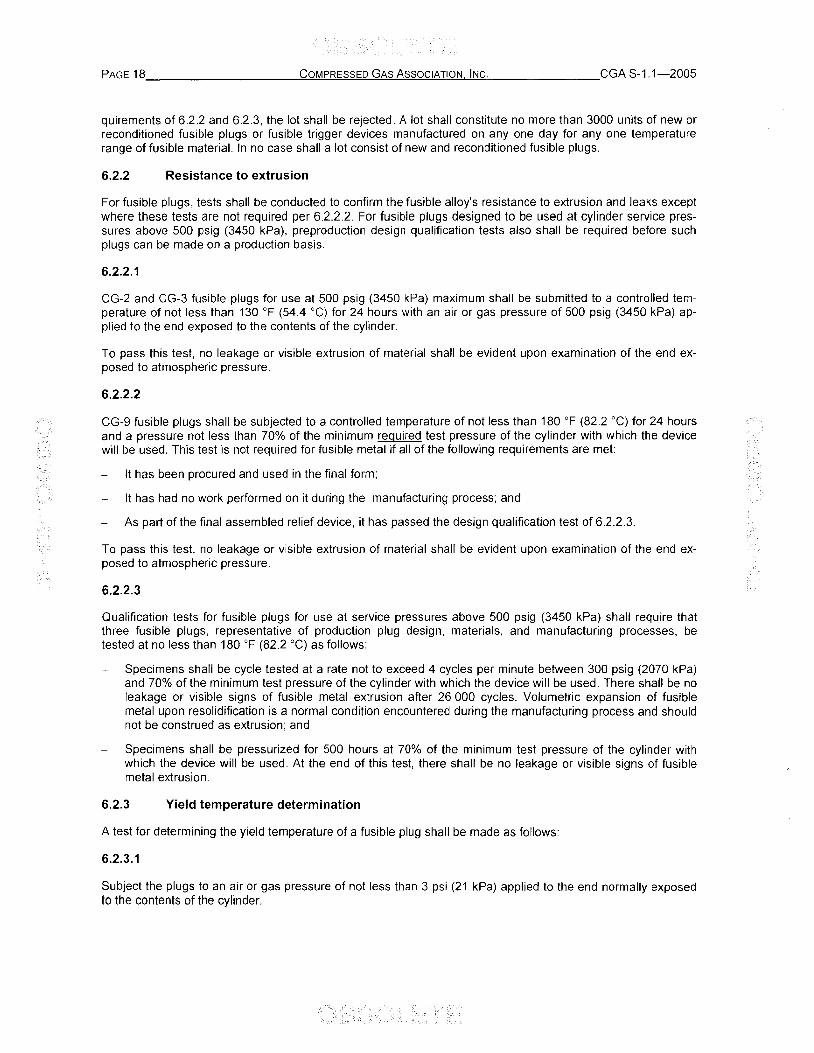
quirements of 6.2.2 and 6.2.3, the lot shall be rejected. A lot shall constitute no more than 3000 units of new or reconditioned fusible plugs or fusible trigger devices manufactured on anyone day for anyone temperature range of fusible material. In no case shall a lot consist of new and reconditioned fusible plugs.
6.2.2 Resistance to extrusion
For fusible plugs, tests shall be conducted to confirm the fusible alloy's resistance to extrusion and leaks except where these tests are not required per 6.2.2.2. For fusible plugs designed to be used at cylinder service pressures above 500 psig (3450 kPa), preproduction design qualification tests also shall be required before such plugs can be made on a production basis.
6.2.2.1
CG-2 and CG-3 fusible plugs for use at 500 psig (3450 kPa) maximum shall be submitted to a controlled temperature of not less than 130 of (54.4 0c) for 24 hours with an air or gas pressure of 500 psig (3450 kPa) applied to the end exposed to the contents of the cylinder.
To pass this test, no leakage or visible extrusion of material shall be evident upon examination of the end exposed to atmospheric pressure.
6.2.2.2
CG-9 fusible plugs shall be subjected to a controlled temperature of not less than 180 OF (82.2 °C) for 24 hours and a pressure not less than 70% of the minimum required test pressure of the cylinder with which the device will be used. This test is not required for fusible metal if all of the following requirements are met:
It has been procured and used in the final form;
It has had no work performed on it during the manufacturing process; and
As part of the final assembled relief device, it has passed the design qualification test of 6.2.2.3.
To pass this test, no leakage or visible extrusion of material shall be evident upon examination of the end exposed to atmospheric pressure.
6.2.2.3
Qualification tests for fusible plugs for use at service pressures above 500 psig (3450 kPa) shall require that three fusible plugs, representative of production plug design, materials, and manufacturing processes, be tested at no less than 180 OF (82.2 0c) as follows:
Specimens shall be cycle tested at a rate not to exceed 4 cycles per minute between 300 psig (2070 kPa) and 70% of the minimum test pressure of the cylinder with which the device will be used. There shall be no leakage or visible signs of fusible metal extrusion after 26 000 cycles. Volumetric expansion of fusible metal upon resolidification is a normal condition encountered during the manufacturing process and should not be construed as extrusion; and
Specimens shall be pressurized for 500 hours at 70% of the minimum test pressure of the cylinder with which the device will be used. At the end of this test, there shall be no leakage or visible signs of fusible metal extrusion.
6.2.3 Yield temperature determination
A test for determining the yield temperature of a fusible plug shall be made as follows:
6.2.3.1
Subject the plugs to an air or gas pressure of not less than 3 psi (21 kPa) applied to the end normally exposed to the contents of the cylinder.

CGA S-1.1-2005 _______ -"'C-"'O-"'M:.:..P:..:.RE::.:S""S:..=E""D....::G"'-A..:=S:....:.A-"S""S'-"O'-"C:.:.:.1A.!.-'T.:..::IO"-'-N"'"'-"IN"'C"-'-. __________ PAGE 19
6.2.3.1.1
While subjected to this pressure, the plugs shall be immersed in a water bath or a glycerin water bath at a temperature of not more than 5 of (2.8 0c) below the specified minimum yield temperature and held in that temperature range for a period of at least 10 minutes.
6.2.3.1.2
The temperature of the bath shall then be raised at a rate not in excess of 1 of (0.6 0c) per minute during which the pressure may be increased to not more than 50 psi (345 kPa). When the metal weakens sufficiently to produce leakage of air or gas, the temperature of the bath shall be recorded as the yield temperature of the plugs. Yielding shall occur within 10 minutes after the maximum allowable yield temperature has been reached and stabilized and yielding shall not exceed the temperature limits specified in Section 3 for that type of fusible plug.
6.2.3.2
As an alternate method, after passing the portion of the test given in 6.2.3.1.1 at a temperature of not more than 5 OF (2.8 °C) below the specified minimum yield temperature, the plugs may be immediately immersed in another bath held at a temperature not exceeding the specified maximum yield temperature. If air or gas leakage occurs within 10 minutes at that temperature, the requirements have been met.
6.2.3.3
Variation in temperature within the liquid bath in which the plug is immersed for either test in 6.2.3.1 or 6.2.3.2 shall be kept to a minimum by stirring while making these tests.
6.2.4 Chlorine service
Fusible plugs to be used in chlorine service shall meet the requirements of The Chlorine Institute, Inc. See Drawing No. 112 in CI Pamphlet 17, Packaging Plant Safety and Operational Guidelines-Revision 1 [10].
6.3 Tests of CG-1 rupture disk devices
6.3.1 Rupture disk burst pressure measurement
The production of rupture disks shall be segregated into lots of not more than 3000 disks with appropriate control exercised to ensure uniformity of production. Representative samples shall be selected at random for testing to verify the rated bursting pressure. The number of samples selected shall be appropriate for the manufacturing procedures followed, but at least two samples shall be tested from each lot. Samples shall be mounted in a proper holder with a pressure opening having dimensions identical with that in the device in which it is to be used and submitted to a burst test at a temperature not lower than 60 OF (15.6 °C) nor higher than 160 OF (71.1 °C). The test pressure may be raised rapidly to 85% of the rated burst pressure, held there for at least 30 seconds, and thereafter shall be raised at a rate not in excess of 100 psi (689 kPa) per minute, until the disk bursts. The actual burst pressure of the disk shall not be in excess of its rated burst pressure and not less than 90% of its rated burst pressure.
6.3.1.1
For rupture disks for DOT-39 and TC-39M cylinders, see 4.2.2.
6.3.1.2
For CTCIDOT-4L and TC-4LM cylinders, the actual burst pressure of the disk shall not exceed 105% of its rated burst pressure and shall not be less than 90% of its rated burst pressure.
6.3.1.3
If the actual burst pressure is not within the limits prescribed above, the entire lot of rupture disks shall be rejected. If the manufacturer so desires, four more disks selected at random from the same lot may be subjected

to the same test. If all four additional disks meet the requirement, the lot may be used; otherwise, the entire lot shall be rejected. Any elevated temperature determination may be arrived at by tests conducted at room temperature provided that the relation of burst pressure to different temperatures is established by test for the type of material used.
6.3.2 Rupture disk holder test
The production of rupture disk holders (that part containing the pressure opening) of 3000 or less shall be considered a lot. Two representative holders selected at random from the lot shall be assembled with proper rupture disks from an acceptable lot as tested in 6.3.1 and subjected to the burst pressure test of 6.3.1. The actual burst pressure shall not be in excess of the rated burst pressure or less than 85% of the rated burst pressure of the disk. For CTC/OOT -4L and TC-4LM cylinders, the actual burst pressure of the disk shall not exceed 105% and shall not be less than 90% of its rated burst pressure. If the actual burst pressure at a temperature not less than 60 of (15.6 °C) or more than 160 of (71.1 0c) is not within the above limits, the entire lot of rupture disk holders shall be rejected. If the manufacturer desires to requalify the lot, he may subject four more holders selected as above from the same lot to the same test. If all four holders meet the requirement, the lot may be used; otherwise, the entire lot shall be rejected. Any elevated temperature determinations may be arrived at by tests conducted at room temperature provided that the relation of burst pressure to different temperatures is established by test for the type of material used.
6.3.3 Combined rupture disk and holder tests
Testing of the assembled rupture disk and holder for detailed requirements specified in 6.3.1 and 6.3.2 in lieu of individual tests will be considered as complying with requirements of both 6.3.1 and 6.3.2.
6.3.4 Affect of temperature on rupture disk tests
It is recognized that the rated burst pressure of a rupture disk corresponds to only one specific design temperature within the range of 60 OF (15.6 0c) to 160 of (71.1 °C). Note should be taken that different results will be obtained when rupture disks are tested at different temperatures. It is therefore necessary that the temperature be specified at which the rated burst pressure applies. This combination of pressure and temperature is what is used to meet the performance requirements of 6.3. (Example: 3000 psig (20 685 kPa) at 60 of (15.6 °C); 3000 psig (20 685 kPa) at 160 of (71.1 °C), etc.)
Room temperature testing may be used to qualify rupture disks designed for use at elevated temperatures. (Example: not exceeding 160 OF [71.1 0c] provided there is a correlation between room temperature and elevated temperature conditions as determined by prior testing.)
6.4 Tests of CG-4 and CG-5 combination rupture-disk/fusible-plug pressure relief devices
6.4.1
A lot (batch) of rupture-disklfusible-plug devices shall be defined as the production, not exceeding one 10-hour shift, of anyone rated burst pressure and anyone yield temperature. Two representative assembled devices shall be selected at random from a lot and submitted to a performance test conducted as follows:
6.4.1.1
Each assembled device shall be subjected to a pressure of 70% to 75% of the rated burst pressure of the rupture disk used and while under this pressure shall be immersed in a liquid bath held at a temperature not more than 5 of (2.8 °C) below the minimum specified yield temperature of the fusible metal for at least 10 minutes. The fusible metal shall not show signs of yielding such as melting. The temperature of the bath shall then be raised at a rate not in excess of 1 OF (0.6 °C) per minute without material change in pressure. Yielding shall occur within 10 minutes after the maximum allowable yield temperature has been reached and stabilized. Yielding shall be considered as occurring when the fusible alloy starts to flow. There shall be no leakage of air or gas.

CGA S-1.1-2005 ______ --'==C~O:.!::M!!...P~R!;o:ES~S~E~D~G~A~S~A.!.:=s~s~O~CI~A.!...!TI~O!:!.NJ...!' I!:!.NC~.'--_________ PAGE 21
6.4.1.2
The rupture disk shall then be tested in accordance with the requirements of 6.3.1. The device may be removed from the bath for this test.
6.4.1.3
As an alternative to tests in 6.4.1.1 and 6.4.1.2, the rupture disk and fusible metal may be tested separately to the requirements of 6.2.3 and 6.3.1 providing the design of the device will allow for the separation of the parts and the separate tests.
6.4.1.4
If either of the two representative devices fails to meet the requirements given in 6.4.1.1, 6.4.1.2, or 6.4.1.3, the entire lot shall be rejected. If the manufacturer desires to requalify the lot, he may subject four more such devices selected at random to the same test. If all four additional devices meet the requirements, the lot may be used.
6.5 Tests of CG-8 rupture disk/pressure relief valve device
6,5.1
The rupture disk portion of a CG-8 device shall be tested in accordance with the requirements of 6.3.1.
6.5.2
The pressure relief valve portion of a CG-8 device shall be tested in accordance with the requirements of 6.6.1.
6.6 Tests of CG-7 pressure relief valves
6.6.1
Each pressure relief valve, except those for 00T-39 and TC-39M cylinders, shall be subjected to an air or gas pressure test to determine the start-to-discharge pressure of the device. The start-to-discharge pressure shall not be less than 75% or more than 100% of the minimum test pressure of the cylinder.
6.6.2
Pressure relief valves for 00T-39 and TC-39M cylinders shall be subjected to an air or gas pressure test to determine the following:
6.6.2.1
Each pressure relief valve shall be tested for leakage at the cylinder test pressure for a minimum of 30 seconds using a water seal of not over 4 in (102 mm) on the outlet of the pressure relief valve or by any other method equally as sensitive. Any valve exhibiting leakage shall be rejected.
6.6.2.2
Two pressure relief valves taken from each lot of 3000 valves or less shall be subjected to both of the following tests:
a) First, the start-to-discharge pressure shall be determined (see 6.6.1). The start-to-discharge pressure shall not be less than 105% of the cylinder test pressure and not greater than 80% of the minimum cylinder burst pressure; and
b) Second, determine that the device meets its flow rate capacity before the pressure exceeds 80% of the minimum cylinder burst pressure.
If a failure occurs in either of the tests, the entire lot shall be rejected.

6.6.2.3
The following method shall be used to determine the start-to-discharge pressure for CG-7 pressure relief valves.
a) Pressurize the pressure relief valve using air or an inert gas to within approximately 25 psi (172 kPa) of the lower limit of the start-to-discharge pressure range of the device; and
b) Increase the pressure slowly at a rate not to exceed 2 psi (13.8 kPa) per second until the first bubbles are observed from the outlet of the pressure relief valve through the water seal of not more than 4 in (102 mm)' and
c) Record the pressure at which the first bubbles appear as the start-to-discharge pressure of the valve.
Other methods determined to be equally as sensitive in detecting the start-to-discharge pressure may also be used.
6.7 Testing of repaired pressure relief devices
See 8.1.3.
6.8 Performance tests for CG-10 and CG-12 devices
6.8.1 CG-10 device qualification tests
All performance tests shall use three new units per test unless otherwise directed in the following sections.
6.8.1.1 Thermal cycling
The pressure relief device assembly shall be thermally cycled between -40 of and 180 of (-40°C and 82°C) as follows:
a) Place an un pressurized device assembly in a fluid bath maintained at -40 of to -44 of (-40°C to -42 °C) for a period of 2-3 hours. Within 5 minutes of the completion of the cold soak, the device is to be transferred from the cold bath to a fluid bath maintained at 180 OF to 190 OF (82°C to 87°C);
b) Maintain the unpressurized device assembly in a fluid bath maintained at 180 OF to 190 OF (82°C to 87°C) for a period of 2-3 hours. Within 5 minutes of the completion of the warm soak, the device is to be transferred from the warm bath to a fluid bath maintained at -40° F to -44 OF (-40 °C to -42°C);
c) Repeat steps a) and b) until a total of 15 thermal cycles has been completed; and
d) With the assembly tested as outlined in a), b), and c) above, resubmit the device to a fluid bath maintained at -40° F to -44 OF (-40°C to -42°C) for 2-3 hours. Remove the device from the fluid bath and cycle the pressure relief device between not more than 10% of the service pressure and not less than 100% of the service pressure for a total of 100 cycles.
Following the thermal and pressure cycling, the pressure relief device shall meet the requirements of sections 6.8.1.5 and 6.8.2.1.
6.8.1.2 Salt corrosion resistance
Nonpermanent outlet caps shall be removed. Each assembly shall be installed in accordance with the manufacturer's recommended procedure. The device shall be pressurized to 125% of the service pressure and exposed for 144 hours to a salt spray (fog) test as specified in ASTM B 117, Standard Practice for Operating Salt Spray (Fog) Apparatus, except that in the test of one unit, the pH of the salt solution shall be adjusted to 4.0 ± 0.2 by the addition of sulfuric acid and nitric acid in a 2:1 ratio, and in the test of the other two units, the pH of the salt solution shall be adjusted to 10.0 ± 0.2 by the addition of sodium hydroxide [11]. Additionally, both salt solutions shall be aerated to provide oxygen and carbon dioxide.

CGA S-1.1-2005 ______ ~C::.:,O~M:!.!..P.!.!R.=:ES~S""E'_"D'_'G""'A_"'S'_!.A_"'S""S""O""C"_'IA,-,-,TI""OC!,!NJ....!, IC!,!N~C,-. __________ PAGE 23
Following the salt corrosion resistance test, the pressure relief device shall meet the requirements of 6.8.1.5 and 6.8.2.1.
6,8.1.3 Stress corrosion cracking resistance
For pressure relief devices containing components made of a copper alloy, one unit shall be tested as an assembly so the copper alloy components are subjected to the stresses normally imposed on them as a result of assembly. All copper alloy components shall be degreased and then continuously exposed for 10 days to a moist ammonia/air mixture maintained in a glass chamber not larger than 12 in (305 mm) on a side and having a glass cover. Approximately 600 ml of aqueous ammonia having a specific gravity of 0.90 shall be maintained at the bottom of the glass chamber below the samples. The samples shall be positioned 1.5 in (38 mm) above the aqueous ammonia solution and supported in an inert tray. The moist ammonia/air mixture shall be maintained at atmospheric pressure with the temperature constant at 93°F ± 4 OF (34°C ± 2°C). Copper alloy components shall not exhibit cracking or delamination due to this test.
Following the stress corrosion cracking resistance test, the pressure relief device shall meet the requirements of 6.8.1.5 and 6.8.2.1.
6.8.1.4 Vibration
The relief device shall be vibrated for 2 hours in each of 3 orthogonal axes at a frequency of 17 cycles per second (± 5%) and an amplitude of 0.06 in (1.5 mm). Following vibration testing, the pressure relief device shall meet the requirements of 6.8.1.5 and 6.8.2.1.
6.8.1.5 Activation time
The test setup shall be in accordance with CGA C-14 except that a test vessel need not be attached [6]. The test chimney shall be capable of maintaining a gas temperature at 1100 OF ± 20 OF (593°C ± 11°C) where the device assembly is inserted for testing. The test setup shall maintain a heat release rate of 300 000 ± 65 000 BTU/hour. The device to be tested shall not be exposed directly to flame.
Pressurize the assembly to 25% of the rated pressure of the device. Place the device into the chimney and record the time until the device activates.
Acceptable results: The device shall activate within 90 seconds.
6.8.1.6 Design and process Failure Mode and Effects Analysis
Design and process Failure Mode and Effects Analysis (FMEA) shall be performed for device assemblies. Qualification FMEA reports shall be kept on file by the manufacturer and made available to the authorities having jurisdiction upon request. Available references include SAE J1739, Potential Failure Mode and Effects Analysis in Design (Design FMEA) and Potential Failure Mode and Effects Analysis in Manufacturing and Assembly Processes (Process FMEA), and FMEA-3, Potential Failure Mode and Effects Analysis [12, 13].
6.8.1.7 Structural burst test
For devices that do not have a piping interface on the exit of the device, the pressure relief mechanism shall be rendered inoperable and pressurized until failure. For devices that do have a piping interface on the exit of the device, the device shall be fully activated and, with the exit blocked, pressurized until failure. The failure pressure shall be at or above four times the device's maximum rated pressure.
6.8.1.8 Pressure cycle test
Five units of the pressure relief device assembly shall be cycled (1000 x design life [DLl) times between not more than 10% and not less than 125% of the maximum rated pressure. The first 10% of the test cycles shall be conducted at a temperature of 180 OF (82°C). The remaining cycles shall be conducted at 135 OF (57 DC). The maximum pressure cycling rate is 10 cycles per minute.
After the cycling test, the pressure relief device shall meet the requirements of 6.8.1.5 and 6.8.2.1.

6.8.1.9 Accelerated life tests
Five pressure relief device assemblies shall be placed in an oven or liquid bath at a temperature determined by the formula below. The temperature of the device shall be held constant within ± 2 of (± 1°C) throughout the test. Each device shall be pressurized on the inlet of the device to 125% of the maximum rated service pressure and held constant within ± 2% of the test pressure. If a manifold system is used, a suitable method should be used to prevent pressure depletion of the system when one specimen fails.
All five assemblies shall meet 500 hours at the test temperature and pressure.
U.S. customary units
h =e[ln(TTref
f J(1 2.87+ln(OL)J+ln(T)] l l5.57+ln(OL) f
Where:
Trel The reference temperature +135 of
T, The fusible material melt temperature, in degrees F (Fahrenheit) as determined by 6.1.1
h The long-term test temperature in degrees F (Fahrenheit)
OL The design service life in years (1 ::; OL ::; 20)
e Dimensionless number used as the base for calculating natural logarithm, normally calculated to nine decimal places' e = 2.718281828
In Natural logarithm whose base is dimensionless number e
Each sample assembly shall be subjected to the tests outlined in 6.8.1.5 and 6.8.2.1 and meet the acceptance criteria of those tests.
6.8.2 Production batch inspection
One batch of completed devices shall not use multiple batches of fusible material. The batch size of fusible materials shall be limited to what can be produced by one common heat of raw materials (e.g., a single oven melt) but shall not exceed 3000 units. The fusible material yield temperature shall be determined in accordance with 6.1.1. Batch sizes shall be consistent with good manufacturing practice and appropriate levels of inspection using the results of the FMEA performed in accordance with the requirements of 6.8.1.6.
Production inspection tests shall use units selected at random. The tests shall be conducted on fusible materials, device components, and finished device assemblies.
When the test results fail to meet requirements, the relief device or component batch shall be rejected. Retest of a rejected batch is authorized if the equipment or procedure was faulty. One retest of a rejected batch is authorized if an improper test was made due to the presence of a defect in the specimen. A batch shall be 100% inspected to remove defective assemblies or components from the batch. A second sample shall then be selected from the batch and tested. The batch is considered acceptable if the second sample meets the batch criteria.
6.8.2.1 Leakage
Each pressure relief device assembly shall be pressurized to 125% of the rated pressure of the device. The pressure relief device assembly shall not leak gas at a rate greater than 8 scc/hr of helium.

CGA S-1.1-2005 _______ C=O:.:..:M'-'PR'-'.!E=-'S""S""E.=:.D.."G"'-A.:.:=S:..:..A.."s""s""O""C.:.:..IA:...:.T-",IO,-,-N,....., .:.:.IN"",C:..:... __________ PAGE 25
6,9 Performance tests for CG-11 devices
6.9.1 CG-11 device qualification tests
All performance tests shall use three new units per test unless otherwise directed in the following sections.
6,9.1.1 Thermal cycling
The pressure relief device assembly shall be thermally cycled between -40 OF and 180 OF (-40 °C and 82°C) as follows:
a) Place an unpressurized device assembly in a fluid bath maintained at -40 OF to -44 OF (-40°C to -42 0c) for a period of 2-3 hours. Within 5 minutes of the completion of the cold soak the device is to be transferred from the cold bath to a fluid bath maintained at 180 OF to 190 OF (82°C to 88°C)"
b) Maintain the unpressurized device assembly in a fluid bath maintained at 180 OF to 190 OF (82°C to 88°C) for a period of 2-3 hours. Within 5 minutes of the completion of the warm soak, the device is to be transferred from the warm bath to a fluid bath maintained at -40° F to -44 OF (-40 °C to -42°C);
c) Repeat steps a) and b) until a total of 15 thermal cycles has been completed' and
d) With the assembly tested as outlined in a) b), and c) above, resubmit the device to a fluid bath maintained at -40° F to -44 OF (-40°C to -42°C) for 2-3 hours. Remove the device from the fluid bath and cycle the pressure relief device between not more than 10% of the service pressure and not less than 100% of the service pressure for a total of 100 cycles.
Following the thermal and pressure cycling, the pressure relief device shall meet the requirements of 6.9.2 and meet acceptance criteria of the tests.
6.9.1.2 Salt corrosion resistance
Each assembly shall be installed in accordance with the manufacturer's recommended procedure. The device shall be pressurized to 80% of the start-to-discharge pressure and exposed for 144 hours to a salt spray (fog) test as specified in ASTM 8117 except that in the test of one unit. the pH of the salt solution shall be adjusted to 4.0 + 0.2 by the addition of sulfuric acid and nitric acid in a 2: 1 ratio, and in the test of the other two units the pH of the salt solution shall be adjusted to 10.0 + 0.2 by the addition of sodium hydroxide [111. Additionally both salt solutions shall be aerated to provide oxygen and carbon dioxide.
Following the salt corrosion resistance test the pressure relief device shall meet the requirements of 6.9.2 and meet acceptance criteria of the tests.
6.9.1.3 Stress corrosion cracking resistance
For pressure relief devices containing components made of a copper alloy, one unit shall be tested as an assembly so the copper alloy components are subjected to the stresses normally imposed on them as a result of assembly. All copper alloy components shall be degreased and then continuously exposed for 10 days to a moist ammonia/air mixture maintained in a glass chamber not larger than 12 in (305 mm) on a side and having a glass cover. Approximately 600 ml of aqueous ammonia having a specific gravity of 0.90 shall be maintained at the bottom of the glass chamber below the samples. The samples shall be pOSitioned 1.5 in (38 mm) above the aqueous ammonia solution and supported in an inert tray. The moist ammonia/air mixture shall be maintained at atmospheric pressure with the temperature constant at 93 OF + 4 OF (34°C + 2°C). Copper alloy components shall not exhibit cracking or delamination due to this test.
Following the stress corrosion cracking resistance test the pressure relief device shall meet the requirements of 6.9.2 and meet acceptance criteria of the tests.
6.9.1.4 Vibration
The relief device shall be vibrated for 2 hours in each of 3 orthogonal axes at a frequency of 17 cycles per second (+ 5%) and an amplitude of 0.06 in (1.5 mm). Following vibration testing, the pressure relief device shall meet the requirements of 6.9.2 and meet acceptance criteria of the tests.

6.9.1.5 Design and process Failure Mode and Effects Analysis
Design and process FMEA(s) shall be performed for device assemblies. Qualification FMEA reports shall be kept on file by the manufacturer and made available to the authorities having jurisdiction upon request. Available references include SAE J1739 and FMEA-3 [12 131.
6.9.1.6 Structural burst test
For devices that do not have a piping interface on the exit of the device the pressure relief mechanism shall be rendered inoperable and pressurized until failure. For devices that do have a piping interface on the exit of the device the device shall be fully activated and, with the exit blocked pressurized until failure. The failure pressure shall be at or above four times the device's maximum start-to-discharge pressure.
6.9.1.7 Pressure cycle test
Place the device in a thermal chamber maintained at 180 of to 190 of (82°C to 88°C). Cycle the pressure relief valve from 10% of the device's actual start-to-discharge pressure to device actuation for 1000 cycles at no more than 10 cycles per minute. Decrease the temperature in the thermal chamber to 135 of + 5 of. Cycle the pressure relief valve from 10% of the device set pressure to device actuation for 9000 cycles at no more than 10 cycles per minute.
The acceptance criteria are as follows:
the valve shall reseal at every cycle' and
the start-to-discharge pressure shall be within the prescribed range for each cycle.
Following the pressure cycle test. CG-11 devices shall meet the requirements of 6.9.2.1.
6.9.1.8 Contained gas corrosion resistance
The outlet port of the pressure relief device shall be sealed. The pressure relief device assembly shall be pressurized through the inlet with the target application gas 10 125% of the maximum slart-Io-discharge pressure of Ihe device and soaked for 500 hours at 70 of (21.1 0c) followed by 100 hours at 180 of (82°C). Each assembly shall then be subjected to the tests outlined in 6.9.2 and meet acceptance criteria of the tests.
6.9.2 Production tests for CG-11 devices
6.9.2.1 Pressure tests
Every device manufactured shall be subjected to an air or gas pressure test to determine the start-to-discharge pressure of the device. The start-to-discharge pressure shall not be less than 90% or more than 100% of the flow rating pressure for which the device is designed. Also it shall be determined that each device is capable of reseating at a pressure not less than 85% of the flow rating pressure for which the device is designed.
6.9.2.2 Leakage
Each pressure relief device assembly shall be pressurized to 80% of the start-to-discharge pressure of the device. The pressure relief device assembly shall not leak gas at a rate greater than 8 scc/hr of helium.
6.10 Performance tests for CG-12 devices
6.10.1 CG-12 device qualification tests
All performance tests shall use three new units per test unless otherwise directed in the following sections. The characteristics of the device applying the CG-10 properties shall be tested in accordance with 6.8.1.1 through 6.8.1.9. The characteristics of the device applying the CG-11 properties shall be tested in accordance with 6.9.1.1 through 6.9.1.8.

CGA S-1.1-2005 ______ ----::C~O::..!!M~P~R=cES~S~E:!::D~G~A~S:..!.A..!:os""s~O~C~IA,"-,TI~O:!.!N.I-!' I.!.!N~C.=--_________ PAGE 27
6.10.2 Production tests
6.10.2.1 Production batch inspection
One batch of completed devices shall not use multiple batches of fusible material. The batch size of fusible materials shall be limited to what can be produced by one common heat of raw materials (e.g. a single oven melt) but shall not exceed 3000 units. The fusible material yield temperature shall be determined in accordance with 6.1.1. Batch sizes shall be consistent with good manufacturing practice and appropriate levels of inspection using the results of the FMEA performed in accordance with the requirements of 6.8.1.6.
Production inspections test shall use units selected at random. The tests shall be conducted on fusible materials, device components and finished device assemblies.
When the test results fail to meet requirements, the relief device or component batch shall be rejected. Retest of a rejected batch is authorized if the equipment or procedure was faulty. One retest of a rejected batch is authorized if an improper test was made due to the presence of a defect in the specimen. A batch shall be 100% inspected to remove defective assemblies or components from the batch. A second sample shall then be selected from the batch and tested. The batch is considered acceptable if the second sample meets the batch criteria.
6.10.2.2 Pressure tests
Every device manufactured shall be subjected to an air or gas pressure test to determine the start to discharge pressure of the device. The start to discharge pressure shall not be less than 90% or more than 100% of the flow rating pressure for which the device is designed. Also it shall be determined that each device is capable of reseating at a pressure not less than 85% of the flow rating pressure for which the device is designed.
6.10.2.3 Leakage
Each pressure relief device assembly shall be pressurized to 80% of the start-to-discharge pressure of the device. The pressure relief device assembly shall not leak gas at a rate greater than 8 scc/hr of helium.
7 Identification requirements
It is the purpose of this section to list certain safeguards or guidelines so that pressure relief device performance may not be jeopardized by improper service practices. The goal is to make it possible to identifv the manufacturer of the device and to have the main replaceable parts if any, so identified or coded that it can be readily determined whether parts are intended to function together what operating pressure range or temperature range they provide for and whether they have adequate flow capacity for the cylinder with which they are to be employed. This can usually be determined by reference to manufacturer's published data.
NOTE-Pressure relief devices used on 00T-39 and TC-39M cylinders are exempt from the marking requirements of this section.
See Table 7 for a list of identification requirements for pressure relief devices.
7,1
Suitable marking (for example name logo or symbOl) shall be provided to identify the manufacturer of the pressure relief device.
7,2
Dates of manufacture and/or replacement shall be designated with 4 characters. The first 2 characters shall be the week of the year and may be followed by space or dash. The last 2 characters shall be the last 2 numbers of the year. A device manufactured in the first week of the year 2004 could appear as 01-04, 0104, or 01 04.
7.3
Performance or operational values that appear on the device shall include their associated units of these values. Standard abbreviation of units is allowed.
7.4
When rupture disks and pressure opening parts are designed to be replaced as individual parts, they shall be marked to indicate the rated burst pressure (when used in conjunction with the proper mating part) the flow capacity and the manufacturer. Suggested methods of marking follow:
7.5
Stamp with manufacturer's name or trademark and rated burst pressure or identifying part number on the part containing the pressure opening;
Ink or otherwise mark the number on the rupture disk or apply some other code mark to facilitate determination of burst pressure range and the proper mating part; or
When rupture disk and pressure opening parts are combined in a factory assembled pressure relief device designed to be replaced as a unit (CG-1, CG-4, or CG-5) the assembly shall be externally marked or coded to indicate the rated burst pressure flow capacity manufacturer and yield temperature if applicable.
Fusible plugs or those devices incorporating a fusible trigger shall be marked (to be visible after installation) indicating the operating (yield) temperature of the device. CG-9 devices shall be marked 217 OF (102.7 0c) to indicate the operating temperature.
7.6
The flow capacity of pressure relief valve incorporated in combination devices (CG-8 CG-12) shall be the relief capacity of the relief valve portion only.
7.7
All markings except for those specified in 7.1 and 7.2 may be coded. Coding deSignations shall be determinable from the manufacturer. Coding may incorporate but not be limited to the use of references to manufacturers published data, symbols, and/or colors.
7.8
Coding of information is not permitted on CG-9 devices.
8 Maintenance requirements for pressure relief devices
8.1 General practices
8.1.1 Cylinder and pressure relief device care
As a precaution to keep cylinder pressure relief devices in reliable operating condition, care shall be taken in the handling or storage of compressed gas cylinders to avoid damage. Care also shall be exercised to avoid plugging of pressure relief device channels and parts by paint or other foreign matter, which could interfere with the functioning of the device. Only trained personnel shall be allowed to service pressure relief devices. Only assemblies or original manufacturer's parts shall be used in the repair of pressure relief devices unless the interchange of parts has been proven by suitable test.
8.1.2 Industrial motor fuel applications
For all industrial motor fuel applications, cylinder pressure relief devices or their discharge outlet piping shall be equipped with a device to prevent plugging of the external relief device channel. Any such device shall not adversely restrict the operating pressure or flow rating of the pressure relief device.
CGA S-1.1-2005 _______ -"'C-"'o.:.:;Mc:....P:....:.RE=S=S=E=O....;:G""A-"'S:...:A...:;s=s""o""c"'-lA..:...:T-'-'IO""'N.:..>....!!IN"-'C""'. __________ PAGE 29
8.1.3 Repaired or reconditioned pressure relief devices
New pressure relief devices that are found to be in noncompliance with Section 6 of this standard may be repaired by the manufacturer provided they are retested as required to confirm that they satisfy the requirements of this standard.
CG-2, CG-3, CG-7, CG-8 (the pressure relief valve portion), CG-9, CG-10, CG-11. and CG-12 devices shall not be reconditioned except for external cleaning. No attempt should be made to replace or refill the fusible metal in devices that have been in service. No attempt should be made to replace parts in or adjust the pressure setting on CG-7, CG-11. or CG-12 devices once the manufacturer has set them.
8.2 Routine checks when filling cylinders
Each time a compressed gas cylinder is received for refilling, all pressure relief devices shall be examined externally for corrosion, damage, rust, presence of a protective device as specified in 8.1.2, plugging of external pressure relief device channels, and mechanical defects such as leakage or extrusion of fusible metal. This examination does not apply to CTC/DOT-4L or TC-4LM cylinders. If there is any doubt regarding the suitability of the pressure relief device for service, the cylinder shall not be filled until it is equipped with a suitable device.
9 Periodic replacement of pressure relief devices
9.1 CG-7 pressure relief valve
Cylinders shall not be charged and shipped if the relief device requirements of 9.1.1 and 9.1.2 are not fulfilled.
9.1.1
All pressure relief valves (CG-7) other than those in industrial motor fuel service shall be replaced or requalified within 10 years after the date of manufacture of the relief valve. CG-7 devices designed for requalification may be requalified. Requalification shall be in accordance with Appendix B. Requalified valves shall be retested on a 5-year frequency. Requalified valves shall be permanently marked to identify the particular valve, requalification date, and requalifier. The requalifier shall certify the requalified valves meet the requirements of Appendix B. Further, the requalifier shall maintain records of the most recent test for a minimum of 6 years from the requalification date of the valve.
9.1.2
All pressure relief valves (CG-7) in industrial motor fuel service shall be replaced with a new or unused valve within 10 years after the date of manufacture of the relief valve or within the requalification period of the cylinder on which they are installed. Requalification of these pressure relief valves is not permitted.
9.2 CG-8 rupture disk/pressure relief valve
The pressure relief valve portion of a CG-8 system shall be replaced or requalified in accordance with the requirements of 9.1.
9.3 CG-11 and CG-12 pressure cycling relief valve
CG-11 and CG-12 devices shall be removed from service within their stated design life, which is marked on the valve and cannot exceed 10 years from the original manufacture date of the valve.
10 References
Unless otherwise specified, the latest edition shall apply.
[1] Code of Federal Regulations, Title 49 (Transportation) Parts 100-180, Superintendent of Documents, U.S. Government Printing Office, Washington, DC 20402. www.gpoaccess.gov
[2] Transportation of Dangerous Goods Regulations, Transport Canada, Canadian Government Publishing, Public Works and Government Services Canada, Ottawa, ON K1A OS9, Canada. www.tc.qc.ca
[3] CGA S-1 .2, Pressure Relief Device Standards-Part 2-Cargo and Portable Tanks for Compressed Gases, Compressed Gas Association, Inc., 4221 Walney Rd., 5th Floor, Chantilly, VA 20151. www.cganet.com
[4] CGA S-1 .3, Pressure Relief Device Standards-Part 3-Stationary Storage Containers for Compressed Gases, Compressed Gas Association, Inc., 4221 Walney Rd., 5th Floor, Chantilly, VA 20151. www.cganet.com
[5] CGA P-11, Metric Practice Guide for the Compressed Gas Industry, Compressed Gas Association, Inc., 4221 Walney Rd., 5th Floor, Chantilly, VA 20151. wwwcganelcom
[6] CGA C-14, Procedures for Fire Testing of DOT Cylinder Pressure Relief Device Systems, Compressed Gas Association, Inc., 4221 Walney Rd., 5th Floor, Chantilly, VA 20151. www.cganelcom
[7] CGA C-12, Qualification Procedure for Acetylene Cylinder Design, Compressed Gas Association, Inc., 4221 Walney Rd., 5th Floor, Chantilly, VA 20151. www.cganet.com
[8] Gas Measurement Committee Report No.3, Orifice Metering of Natural Gas, American Gas Association, 400 N. Capitol SI, NW, Washington, DC 20001. (Reprinted with revisions 1969) www.aga.org
[9] ASME PTC 25, Pressure Relief Devices, ASME International, Three Park Ave., New York, NY 10016. www.asme.org
[10] CI Pamphlet 17, Packaging Plant Safety and Operational Guidelines-Revision 1, The Chlorine Institute, Inc., 1300 Wilson Blvd., Rosslyn, VA 22209. www.cI2.com
[11] ASTM B117, Standard Practice for Operating Salt Spray (Fog) Apparatus, ASTM International, 100 Barr Harbor Dr., West Conshohocken, PA 19428. www.astm.org
[12] SAE J1739, Potential Failure Mode and Effects Analysis in Design (Design FMEA) and Potential Failure Mode and Effects Analysis in Manufacturing and Assembly Processes (Process FMEA) and Effects Analysis for Machinery (Machinery FMEA) , Society of Automotive Engineers, 400 Commonwealth Dr., Warrendale, PA 15096. www.sae.org
[13] FMEA-3, Potential Failure Mode and Effects Analysis, Automotive Industry Action Group, 26200 Lahser Rd., Suite 200, Southfield, MI 48034. www.aiag.org
[14] Heller, F.J., How to Size Safety Relief Devices, 1954, Phillips Petroleum Company.
11 Additional references
CGA V-1, Compressed Gas Association Standard for Compressed Gas Cylinder Valve Outlet and Inlet Connections, Compressed Gas Association, Inc., 4221 Walney Rd., 5th Floor, Chantilly, VA 20151. www.cganelcom
NFPA 58, Liquefied Petroleum Gas Code, National Fire Protection Association, 1 Batterymarch Park, Quincy, MA 02269. www.nfpa.org
ASME Boiler and Pressure Vessel Code, ASME International, Three Park Avenue, New York, NY 10016. www.asme.org
CSA B339, Cylinders, Spheres, and Tubes for the Transportation of Dangerous Goods, Canadian Standards Association, 5060 Spectrum Way, Mississauga, ON L4W 5N6, Canada. www.csa.ca
CSA B340, Selection and Use of Cylinders, Spheres, Tubes, and Other Containers for the Transportation of Dangerous Goods, Class 2, Canadian Standards Association, 5060 Spectrum Way, Mississauga, ON L4W 5N6, Canada. www.csa.ca

CGA S-1.1-2005 _______ ~C~O""'M"_P:...:.RE::.:S""S'_"E""D_'G"'"A_"'S:..:.A_"s""s'""o'_"c:.::.1A..:..:T-"IO"-'N.:.J..,..!-'IN-'-'C"-'-. __________ PAGE 31
Introduction to Tables
Required pressure relief devices
The types of pressure relief devices listed in Table 1 are acceptable as indicated in Table 3 by a letter symbol or symbols for application on cylinders for various compressed gases and gas mixtures.
If a fire test is required, it shall be performed in accordance with CGA C-14 and CGA C-12 [6, 7). A fire test shall be conducted when the flow capacity of a pressure relief device is sized less than required by formula in this standard.
Requests for types and applications of pressure relief devices other than those listed in Table 1 or Table 3 shall be sent to CGA for assignment and be accompanied by test data as shown on a form as suggested in Appendix A.
Table 1-Types of pressure relief devices
CG-1 Rupture disk
CG-2 165 eF (73.9 ec) Fusible plug for cylinder product pressure not exceeding 500 psig (3450 kPa)
CG-3 212 eF (100 ec) Fusible plug for cylinder product pressure not exceeding 500 psig (3450 kPa)
CG-4 Rupture disk with 165 eF (73.9 ec) fusible alloy backing
CG-5 Rupture disk with 212 eF (100 ec) fusible alloy backing
CG-7 Pressure relief valve
CG-8 Rupture disk followed by (in series) pressure relief valve
CG-9 217 eF (102.7 ec) Fusible plug for cylinder marked service pressures not exceeding 6000 psig (41400 kPa)
CG-10 Fusible trigger device for cylinder marked service pressure on the device not exceeding 13 100 psig (90300 kPa)
CG-11 Pressure relief valve caQable of activating and reseating multiQle times
CG-12 Pressure relief device combining the general characteristics of a fusible trigger device and a Qressure cycling relief valve

PAGE 32 __________ -'=C'-"O:..:.:M.!!..P.:...:R.=.ES""S"-'E:.=D:....;G""Ac..:;S"-A'--'s""s"-'O"-'C""IA..:..T'-!,;1o""'N..:.. • ...:.I:.:..NC"". _______ eGA S-1.1-2005
Table 2-FTSe numerical code for gas classification
1st Digit - FIRE POTENTIAL
o = inert
2
3
4
5
= supports combustion (oxidizing)
= flammable in air at 68 of (20 °e) and 1 atm
= pyrophoric
= highly oxidizing
= may decompose or polymerize and is flammable
2nd Digit - TOXICITY
o = life supporting (oxygen;:: 19.5% in simple asphyxiant)
1 = Leso > 5000 ppm
2 = 200 ppm < Leso :5 5000 ppm
3 = Leso :5 200 ppm
3rd Digit - STATE OF GAS: (in the cylinder at 70° F (21 ° e) 1)
o = noncryogenic liquefied gas (less than 500 psi [3450 kPa]) 2)_gas withdrawal
1 = noncryogenic liquefied gas (over 500 psi [3450 kPa])-gas withdrawal
2 = liquefied gas (liquid withdrawal) 3)
3 = dissolved/absorbed gas
4 = nonliquefied gas-or cryogenic gas withdrawal (less than 500 psi [3450 kPa])
5 = Europe only
6 = nonliquefied gas between 500 psi and 3000 psi (3450 kPa and 20 680 kPa)
7 = nonliquefied gas above 3001 psi and below 10000 psi (20690 kPa and 68 950 kPa)
8 = cryogenic gas (liquid withdrawal) above -400 OF (-240°C)
9 = cryogenic gas (liquid withdrawal) below -400 OF (-240°C)
4th Digit - CORROSIVENESS:
o = noncorrosive
= non halogen acid forming
2 = basic
3 = halogen acid forming
1) The temperature of the cryogenic gases is always below -130 OF (-90 °e).
2) If pressure at 130 OF (54°C) is over 600 psi (4140 kPa), use digit 1.
3) When separate outlet for liquid withdrawal is specified.

CGA 8-1, 1-2005 _______ C"'-""°!!.!M"-PR~E=.::S""S'_'=E""D_"G""A""S'_CA_"s""s"=O'_"C""IA"_!.T"_'1o""N"'-!!.IN""C",-, __________ PAGE 33
Table 3-Alphabetical list of gases and devices assigned (see notes)
Note 1: When more than one type of device is listed in Table 3 for a particular gas, only one type is required,
Note 2: The symbols used in Table 3 are defined at the end of the table, Interpretation of these symbols is necessary to determine the type of relief device to be used with the specific lading.
Note 3: Type CG-4 and Type CG-5 devices are not acceptable for 110% fill; see 49 CFR 173,302(c) [1],
Note 4: For certain gases, use of pressure relief devices is not permitted, For such gases, the pressure relief device column is marked "Prohibited"; see 49 CFR 173.40 [1].
Note 5: "None required" does not remove the possibility that a pressure relief device may be used,
Note 6: When used in direct medical service, CG-1 devices for carbon dioxide, carbon dioxide/nitrous oxide mixture (liquid), cyclopropane, and nitrous oxide shall be of the projecting type,
Note 7: The statement "device is required in only one end" does not preclude use of a second device at the other end of the cylinder or tube,
CRYOGENIC LIQUIDS
CG-4 CG-5 FTSC CG-1 CG-2 CG-3 165 of 212 of CG-7 CG-8 CG-9 Code Gas Disk 165 of 212 of with disk with disk RV diskJRV 217 OF CG-10 CG-11 CG-12
0180 Argon G
0190 Helium G
2190 Hydrogen G
0180 Neon G
0180 Nitrogen G
4080 Oxygen G
GASES
CG-4 CG-5 FTSC LCso CG-1 CG-2 CG-3 165 OF 212 OF CG-7 CG-8 CG-9 Code ppm Gas Disk 165 OF 212 OF with disk with disk RV diskJRV 217 OF CG-10 CG-11 CG-12
5130 Acetylene F
2200 Acrylonitrile NONE REQUIRED
1060 Air A B B B £:, B
2100 Allene M A
Allylene (See Methylacetylene)
2102 7338 Ammonia, Anhydrous (over 1651b) (None required if a y under 165 Ib)
0303 30 Antimony Pentafluoride PROHIBITED
0160 Argon A B B £:, B
2300 20 Arsine PROHIBITED
0303 20 Arsenic Pentafluoride PROHIBITED
Boron Chloride (See Boron Trichloride)
Boron Fluoride (See Boron Trifluoride)
0203 2541 *Boron Trichloride T BC
0263 806 Boron Trifluoride T T
4303 50 *Bromine Pentafluoride PROHIBITED
4303 180 *Bromine Trifluoride PROHIBITED

PAGE 34 __________ -'=C'""°~M!!..P.!..!R.=.ES""S"_'E==D'_'G""A'_"S""'A'_'s""s""'O""'C~IA'_'_T'_"1o""N.!J...!.IN'-"C"". _______ CGA 8-1.1-2005
CG-4 CG-5 FTSC LCso CG-1 CG-2 CG-3 165 of 212 of CG-7 CG-S CG·9 Code ppm Gas Disk 165 of 212 of with disk with disk RV disk/RV 217 of CG-10 CG-11 CG-12
0203 260 'Bromoacetone T
0100 'Bromochlorodifluoro-methane (R12Bl) or I I (Halon1211)
0100 'Bromochloromethane NONE REQUIRED (Halonl0ll)
0100 Bromodifluoromethane A A (HBFC-22 Bl)
Bromoethylene (See Vinyl Bromide)
Bromomethane (See Methyl Bromide)
3100 Bromotrifluoroethylene C A (Rl13B1)
0100 Bromotrifluoromethane A A (R13B1 or Halon 1301)
5100 220000 1,3 Butadiene, (Inhibited) A
2100 Butane, Normal M A
2100 1-Butene A
2100 2-Butene A
0110 Carbon Dioxide A 6. w Carbon Dioxide/Nitrous
A Oxide Mixture (Liquid)
Carbon Dioxide/Oxygen A
B B 6. Mixture (Gas)
2200 Carbon Disulfide NONE REQUIRED
Carbonic Acid (See Carbon Dioxide)
2260 3760 Carbon Monoxide J J
Carbon Oxysulfide (See Carbonyl Sulfide)
Carbon Tetrachloride (See Tetrachloromethane)
Carbon Tetrafluoride (See Tetrafluoromethane)
Carbonyl Chloride (See Phosgene)
0213 360 Carbonyl Fluoride T
2201 1 700 Carbonyl Sulfide B BC
4203 293 Chlorine (see 6.2.4) H CZT
4303 122 Chlorine Pentafluoride PROHIBITED
4203 299 Chlorine Trifluoride T
2100 Chlorodifluoroethane M M A (R142b)
0100 Chlorodifluoromethane A M M A (R22)
0100 Chlorodifluoromethane/ Chloropentafluoroethane A M M A (Mixture) (R502)
Chloroethane (See Ethyl Chloride)
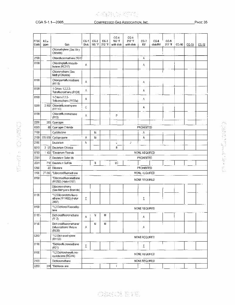
CGA S-1.1-2005 _______ -"'C-"'o~M"__P'_'_RE::.;S""S'_'=E""D__'G""A_"'S'_'A_"S""S'_"o'_"c:.:.:.1A.!.!T..:.:IO"'-N.:.....:.:IN..:.:C"'-. __________ PAGE 35
CG-4 CG-5 FTSC LC so CG-1 CG-2 CG-3 165 of 212 of CG-7 CG-8 CG·g Code ppm Gas Disk 165 of 212 of with disk with disk RV disk/RV 217 of CG-10 CG-11 CG-12
Chloroethylene (See Vinyl Chloride)
2100 Chlorofluoromethane (R31 ) A
0100 Chloroheptafluorocyclo-A A butane (RC317)
Chloromethane (See Methyl Chloride)
0100 Chloropentafluoroethane A A (R115)
0100 1-Chloro-1,2,2,2-A A Tetrafluoroethane (R124)
0100 1-Chloro-2,2,2-A A Trifluoroethane (R133a)
5200 2000 Chlorotnfluoroethylene C A (R1113)
0100 Chlorotrifluoromethane A P
(R13)
2200 350 Cyanogen T
0303 80 Cyanogen Chloride PROHIBITED
2100 Cyclobutane M A
2100 220000 Cyclopropane A M A
2160 Deuterium N J J
0213 3120 Deuterium Chloride B
0203 1100 *Deuterium Fluoride NONE REQUIRED
2301 2 Deuterium Selenide PROHIBITED
2201 710 Deuterium Sulfide B Be
5360 80 Diborane PROHIBITED
1100 27000 *Dibromodifluoroethane NONE REQUIRED
0100 *Dibromodifluoromethane NONE REQUIRED (R12B2) (Halon1202)
Dibromomethane (See Methylene Bromide)
0100 *1,2 Dibromotetrafluoro-ethane (R114B2) (Halon I I 2402)
0100 *1,2 Dichlorodifluoroethy- NONE REQUIRED lene
0100 Dichlorodifluoromethane A M M
A (R12)
0100 Dichlorodifluoromethanel M M Difluoroethane Mixture A A (R500)
0200 *1,2 Dichloroethylene NONE REQUIRED (R1130)
0100 *Dichlorofluoroemethane I I (R21)
0100 *1,2 Dichlorohexafluoro· NONE REQUIRED cyclobutane (RC316)
2100 Dichloromethane NONE REQUIRED
2203 314 *Dichlorosilane T

CG-4 CG-5 FTSC LCso CG-1 CG-2 CG-3 165 of 212 OF CG-7 CG-8 CG-9 Code ppm Gas Disk 165 of 212 OF with disk with disk RV disk/RV 217 of CG-10 CG-11 CG-12
0100 '1,1 Dichlorotetra-I M M I Huoroethane (R114a)
0100 'Dichlorotetrafiuoroethane I M M I (R114)
0100 '2,2 Dichloro-1, 1,1- NONE REQUIRED Trifiuoroethane (R123)
Dicyan (See Cyanogen)
3300 10 'Diethylzinc PROHIBITED
2100 1,1 Difiuoroethane (R152a) M M A
2110 1,1 Difiuoroethylene A B (R1132a)
Difiuoromethane (See Methylene Fluoride)
2102 'Dimethylamine, NONE REQUIRED Anhydrous
Dimethyl Disulfide (See Methyl Disulfide)
2100 Dimethyl Ether A
2100 >5000 'Dimethylsilane NONE REQUIRED
Dimethyl Sulfide (See Methyl Sulfide)
2100 '2,2 Dimethylpropane I 0303 2 Diphosgene PROHIBITED
2110 Ethane ~
Ethanethiol (See Ethyl Mercaptan)
2100 'Ethyl acetylene I I 2100 'Ethyl Chloride I I 0303 36 Ethyldichloroarsine PROHIBITED
2160 Ethylene ~
5200 2920 'Ethylene Oxide SEE 49 CFR 173.323
2100 'Ethyl Ether I 2100 Ethyl Fluoride T
2100 Ethyl Mercaptan NONE REQUIRED
4343 185 Fluorine PROHIBITED
Fluoroform (R23) (See T rifiuoromethane)
2200 622 Germane T
0203 Germanium Tetrafiuoride PROHIBITED
0160 Helium A B B ;:, B ;:, Helium/Oxygen Mixture A B B A
2300 10 Heptafiuorobutyronitrile PROHIBITED
0100 Heptafiuoropropane A A
(HFC-227 ea)
0203 470 Hexafiuoroacetone T T
2100 >5000 Hexaftuorocyclobutene T
0100 Hexafiuoroethane (R116) A B

CGA S-1.1-2005 _______ ;,:.C;,:.O.:.:.:M.:....P'-"RE""S""S'-'=E""O--"G""-A-"'S:....:.A-"s""s'-"o'-"C"'-1A.!..!T.!-"IO"-'-N!.>..!.!.IN-"'C'-'-. __________ PAGE 37
CG·4 CG-5 FTSC LCso CG-1 CG·2 CG-3 165 of 212 of CG-7 CG-S CG-9 Code ppm Gas Disk 165 of 212 of with disk with disk RV disk/RV 217 of CG-10 CG-11 CG-12
0100 Hexafluoropropylene A A
(R1216)
2160 Hydrogen N J J N J N
2130 Hydrogen absorbed in metal alloy (reversible is is ], h h metal hydride 1
0203 2860 Hydrogen Bromide B
0213 3120 Hydrogen Chloride B Q
5301 140 Hydrogen Cyanide PROHIBITED
0203 1 276 *Hydrogen Fluoride NONE REQUIRED
0203 2860 Hydrogen Iodide B
2301 2 Hydrogen Selenide PROHIBITED
2201 712 Hydrogen Sulfide T T
4303 120 *Iodine Pentafluoride PROHIBITED
0203 lodomethane NONE REQUIRED
2100 Isobutane A
2100 Isobutylene A
0160 Krypton A B B 8 B
0303 Lewisite (Dichloro 2-Chloro PROHIBITED Vinyl Arsine)
2160 Methane N J J !2! J
2100 Methylacetylene M A
0200 850 *Methyl Bromide NONE REQUIRED
2100 *3-Methyl-1-Butene I 2100 Methyl Chloride A
0303 Methyldichloroarsine PROHIBITED
2300 Methyl Disulfide NONE REQUIRED
2203 *Methylene Bromide NONE REQUIRED
2110 Methyl Fluoride B
Methylene Chloride (See Dichloromethane)
2110 Methylene Fluoride (R32) A A
2100 *Methyl Formate NONE REQUIRED
0303 *Methyllodide NONE REQUIRED
2201 1350 Methyl Mercaptan NONE REQUIRED
2100 Methylsilane B
2100 Methyl Sulfide NONE REQUIRED
2102 *Monoethylamine NONE REQUIRED
2102 Monomethylamine, NONE REQUIRED
Anhydrous
0303 4 Mustard Gas PROHIBITED
2160 Natural Gas N J J !2! X J
0160 Neon A B B 8 B
2300 20 *Nickel Carbonyl PROHIBITED
4361 115 Nitric Oxide PROHIBITED
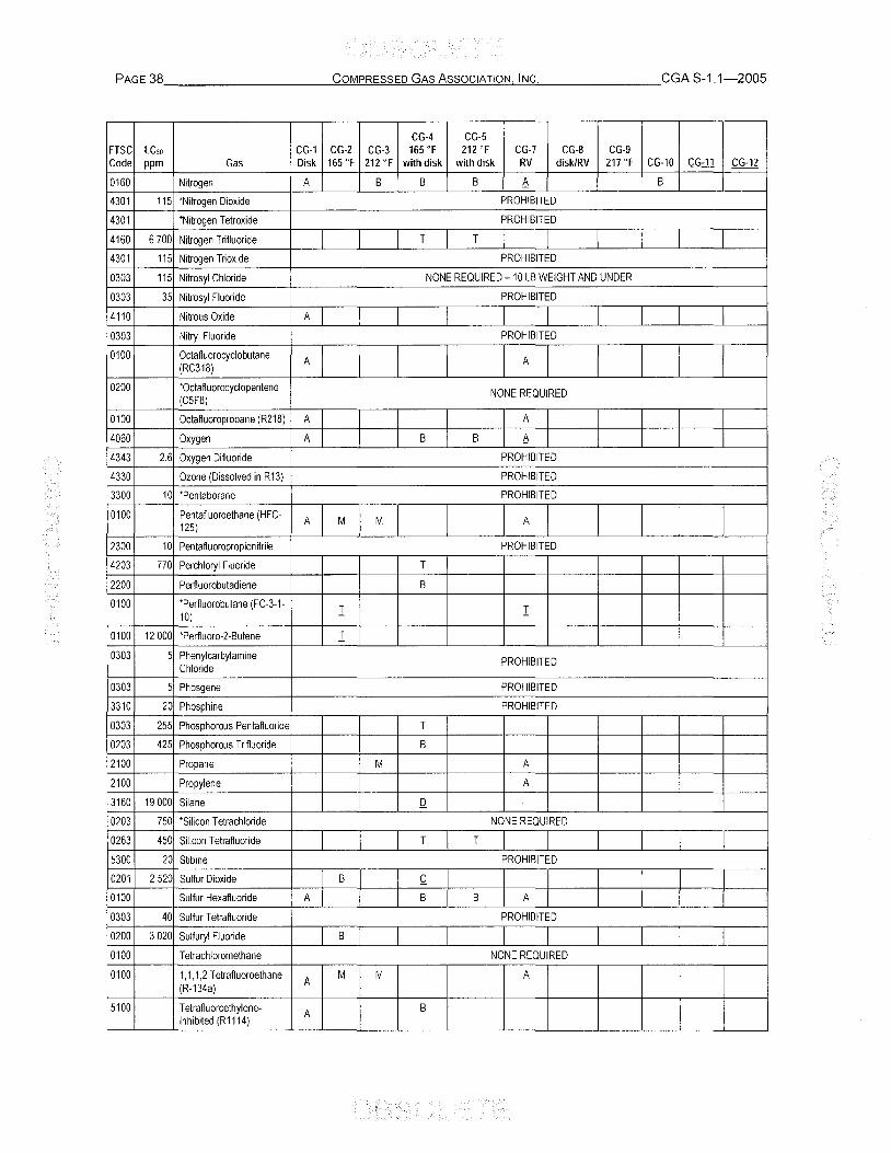
PAGE 38 __________ ~C~O~M.!!..P~R=ES~S~E:.=D~G~A~S:!...A!...lS~S~O~C~IA:!.T:..!.:1o~N..!.J...!.INC!:C=:..o. _______ CGA S-1.1-2005
CG-4 CG-5 FTSC LCso CG-1 CG-2 CG-3 165 of 212 OF CG-7 CG-8 CG-9 Code ppm Gas Disk 165 of 212 OF with disk with disk RV disk/RV 217 of CG-10 CG-11 CG-12
0160 Nitrogen A B B B 6. B
4301 115 'Nitrogen Dioxide PROHIBITED
4301 'Nitrogen Tetroxide PROHIBITED
4160 6700 Nitrogen T rifiuoride T T
4301 115 Nitrogen Trioxide PROHIBITED
0303 115 Nitrosyl Chloride NONE REQUIRED -10 LB WEIGHT AND UNDER
0303 35 Nitrosyl Fluoride PROHIBITED
4110 Nitrous Oxide A
0303 Nitryl Fluoride PROHIBITED
0100 Octafluorocyclobutane A A (RC318)
0200 'Octafluorocyclopentene NONE REQUIRED (C5F8)
0100 Octafluoropropane (R218) A A
4060 Oxygen A B B 6. 4343 2.6 Oxygen Difluoride PROHIBITED
4330 Ozone (Dissolved in R13) PROHIBITED
3300 10 'Pentaborane PROHIBITED
0100 Pentafluoroethane (HFC- A M M A 125)
2300 10 Pentafluoropropionitrile PROHIBITED
4203 770 Perchloryl Fluoride T
2200 Perfluorobutadiene B
0100 'Perfluorobutane (FC-3-1-I I 10)
0100 12000 'Perfluoro-2-Butene I 0303 5 Phenylcarbylamine PROHIBITED
Chloride
0303 5 Phosgene PROHIBITED
3310 20 Phosphine PROHIBITED
0303 255 Phosphorous Pentafluoride T
0203 425 Phosphorous Trifluoride B
2100 Propane M A
2100 Propylene A
3160 19000 Silane Q
0203 750 'Silicon Tetrachloride NONE REQUIRED
0263 450 Silicon Tetrafluoride T T
5300 20 Stibine PROHIBITED
0201 2520 Sulfur Dioxide B Q 0100 Sulfur Hexafluoride A B B A
0303 40 Sulfur Tetrafluoride PROHIBITED
0200 3020 Sulfuryl Fluoride B
0100 Tetrachloromethane NONE REQUIRED
0100 1,1,1,2 Tetrafluoroethane A M M A
(R-134a)
5100 Tetrafiuoroethylene- A B Inhibited (Rll14)
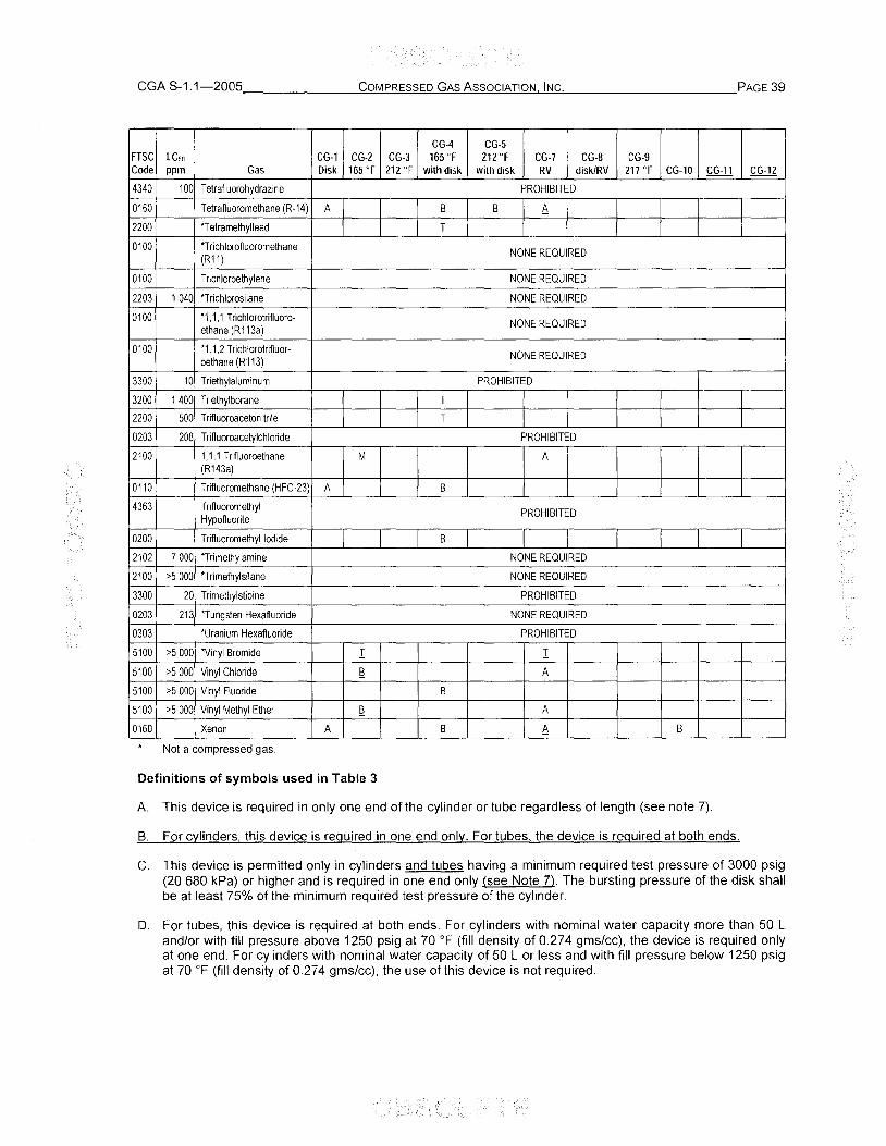
CGA S-1.1-2005 _______ ~C~O!!!M!...PR~E=.::S~S~E~D_"G~A~S~A..!!S"""s~o~CO!!:IA~T~IO~N~IN~C'"'_. __________ PAGE 39
CG·4 CG-5 FTSC LCso CG-1 CG-2 CG-3 165 of 212 of CG-7 CG-8 CG-9 Code ppm Gas Disk 165 of 212 of with disk with disk RV disk/RV 217 of CG-10 CG-11 CG-12
4340 100 Tetrafluorohydrazine PROHIBITED
0160 Tetrafluoromethane (R-14) A B B 6 2200 *Tetramethyllead T
0100 *Trichlorofluoromethane NONE REQUIRED (R11)
0100 Trichloroethylene NONE REQUIRED
2203 1040 *T richlorosilane NONE REQUIRED
0100 *1,1,1 Trichlorotrifluoro-NONE REQUIRED
ethane (R113a)
0100 *1,1,2 Trichlorotrifluor-NONE REQUIRED
oethane (R113)
3300 10 Triethylaluminum PROHIBITED
3200 1400 T riethylborane T
2200 500 T rifluoroacetonitrile T
0203 208 Trifluoroacetylchloride PROHIBITED
2100 1,1,1 Trifluoroethane M A (R143a)
0110 Trifluoromethane (HFC-23) A B
4363 T rifluoromethyl PROHIBITED
Hypofluorite
0200 T rifluoromethyl Iodide B
2102 7000 *Trimethylamine NONE REQUIRED
2100 >5000 *T rimethylsilane NONE REQUIRED
3300 20 Trimethylstibine PROHIBITED
0203 213 *Tungsten Hexafluoride NONE REQUIRED
0303 *Uranium Hexafluoride PROHIBITED
5100 >5000 *Vinyl Bromide I I 5100 >5000 Vinyl Chloride R A
5100 >5000 Vinyl Fluoride B
5100 >5 000 Vinyl Methyl Ether !2 A
0160 Xenon A B 6 B
Not a compressed gas.
Definitions of symbols used in Table 3
A. This device is required in only one end of the cylinder or tube regardless of length (see note 7).
B. For cylinders, this device is required in one end only. For tubes the device is required at both ends.
C. This device is permitted only in cylinders and tubes having a minimum required test pressure of 3000 psig (20680 kPa) or higher and is required in one end only (see Note 7). The bursting pressure of the disk shall be at least 75% of the minimum required test pressure of the cylinder.
D. For tubes, this device is required at both ends. For cylinders with nominal water capacity more than 50 L and/or with fill pressure above 1250 psig at 70 OF (fill density of 0.274 gms/cc), the device is required only at one end. For cylinders with nominal water capacity of 50 L or less and with fill pressure below 1250 psig at 70 OF (fill density of 0.274 gms/cc), the use of this device is not required.

PAGE 40 __________ ..:::C..:::Oc.:.:.M"-P.!..;.R""ES""S""E=D--=G""A..:.:S"-'A'-"S""S"-'O'-"C='A..:..:T..:..:'O"-'N.:..o.,..:.:IN..:..:C"-'. _______ CGA S-1.1-2005
E. This device is required in only one end of the cylinder or tube. regardless of length (see note 7). The device shall be arranged to discharge upwards and unobstructed to the open air in such a manner as to prevent any impingement of escaping gas upon the containers or personnel.
F. The number and location of pressure relief devices for cylinders of any particular size shall be proved adequate as a result of the fire test. Any change in style of cylinder, a filler, or quantity of devices can only be approved if found adequate upon reapplication of the fire test. The fire test shall be conducted in accordance with CGA C-12 [7].
G. This device is required in one end of the cylinder only, regardless of length. A pressure controlling valve as required in 49 CFR 173.316(b) shall also be used [1]. This valve shall be both sized and set so as to limit the pressure in the cylinder to 1-1/4 times its marked service pressure less 15 psi (103 kPa) if vacuum insulation is used. The insulation jacket shall be provided with a pressure-actuated device that will function at a pressure of not more than 25 psig (172 kPa) and provide a minimum discharge area of 0.00012 in2/lb (0.171 mm2/kg) water capacity of cylinder.
An alternate pressure relief valve with a marked set pressure not to exceed 150% of the service pressure may be used in lieu of the rupture disk device if the flow capacity required for relief devices on CTC/OOT 4L and TC-4LM specification insulated cylinders is provided at 120% of marked set pressure. Installation shall provide for:
prevention of moisture accumulation at the seat by drainage away from that area;
periodic drainage of the vent piping; and
avoidance of foreign material in the vent piping.
H. When cylinders are over 55-in (1397-mm) long exclusive of the neck, this device is required in both ends except for cylinders purchased after October 1, 1944, that shall contain no aperture other than that provided in the neck of the cylinder for attachment of a valve equipped with an approved pressure relief device. Chlorine cylinders do not generally exceed 55 in (1397 mm) in length since 49 CFR 173.304(a)(2) Note 2 of DOT regulations requires that cylinders purchased after November 1, 1935, shall not contain over 150 Ib (68 kg) of chlorine [1].
J. For cylinders. this device is required in only one end. For tubes this device is required at both ends and each device shall be arranged to discharge upwards and unobstructed to the open air in such a manner as to prevent any impingement of escaping gas upon the containers or personnel.
K. For cylinders less than 4-1/2-in (114-mm) in diameter and 12-in (305-mm) overall length only. In accordance with 49 CFR 173.301 (f)(5)(i), pressure relief devices are not required for these packages [1J. If relief devices are installed this device is recommended for use.
L. CG-10 and CG-11 devices shall be installed in parallel unless otherwise specified (see 4.1.7).
M. May be used in conjunction with CG-7 (see 4.3.1).
N. This device is required in only one end of tubes. The device shall be arranged to discharge upwards and unobstructed to the open air in such a manner as to prevent any impingement of escaping gas upon the containers or personnel (see Note 7).
P. For use only on tubes; this device is required at both ends.
Q. It is permissible to install a CG-8 device in addition (parallel) to the CG-4 device. It is permitted only at one end of the cylinder, regardless of length.
R. This fusible plug device may be used up to the maximum service pressure of the cylinder for which the device's use is intended but not more than 6000 psig (41 400 kPa). For cylinders, this device is required in only one end. For tubes, this device is required at both ends.
S. Reserved.

CGA S-1.1-2005 _______ -"'C-"'O'-"M"-P'-"RE:.:S""S""E.:::D...,G:!!.A-"'S'-'-A-"s""s'-"o'-"c"'-lA.!..!T.!.":IO"-'-N!J...!!IN-'-"C"-'-. __________ PAGE 41
T. No pressure relief device required by 49 CFR [1]. This device is to be selected if a pressure relief device is used.
W. May be used in parallel with CG-1 (see 4.1.5).
X. May be used in parallel with a CG-7 device (see 4.1.5) at pressures up to the maximum service pressure of the cylinder for which the device's use is intended, but no more than 3600 psig (24 820 kPa).
Y. This device is permitted only in cylinders with a capacity of 1000 Ib (454 kg) or less. When cylinders are over 65-in (1651-mm) long exclusive of the neck, this device is required at both ends. For shorter cylinders, this device is permitted in cylinders having a minimum required test pressure of 3000 psig (20 680 kPa) or higher and is required in one end only. The bursting pressure of the disk shall be at least 75% of the minimum required test pressure of the cylinder.
z. Cylinders over 55-in (1397-mm) long exclusive of the neck are not permitted to use the CG-4 pressure relief device. Also, cylinders manufactured prior to October 1, 1944, are not permitted to be equipped with the CG-4 pressure relief device.
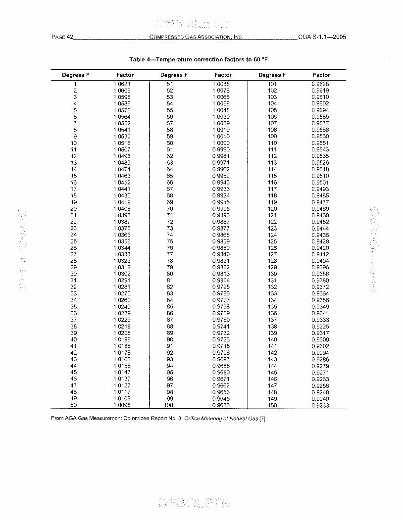
PAGE 42 _________ ~C~O~M:!!..P.!..!R.=.;ES"'"'S~E'_'::D_'=G~A~S:..!.A_"'S""S~O~C~IA""TI~O~N~I~N~C.'__ ______ CGA 8-1.1-2005
Table 4-Temperature correction factors to 60 OF
Degrees F Factor Degrees F Factor Degrees F Factor
1 10621 51 10088 101 0.9628 2 10609 52 10078 102 0.9619 3 1.0598 53 10068 103 0.9610 4 10586 54 10058 104 0.9602 5 10575 55 10048 105 0.9594 6 10564 56 10039 106 0.9585 7 1.0552 57 10029 107 0.9577 8 1.0541 58 10019 108 0.9568 9 1.0530 59 10010 109 0.9560
10 1.0518 60 10000 110 0.9551 11 1.0507 61 0.9990 111 0.9543 12 1.0496 62 0.9981 112 0.9535 13 1.0485 63 0.9971 113 0.9526 14 10474 64 0.9962 114 0.9518 15 1.0463 65 0.9952 115 0.9510 16 1.0452 66 0.9943 116 0.9501 17 1.0441 67 0.9933 117 0.9493 18 1.0430 68 0.9924 118 0.9485 19 1.0419 69 0.9915 119 0.9477 20 1.0408 70 0.9905 120 0.9469 21 1.0398 71 0.9896 121 0.9460 22 1.0387 72 0.9887 122 0.9452 23 1.0376 73 0.9877 123 0.9444 24 1.0365 74 0.9868 124 0.9436 25 1.0355 75 0.9859 125 0.9428 26 1.0344 76 0.9850 126 0.9420 27 1.0333 77 0.9840 127 0.9412 28 1.0323 78 0.9831 128 0.9404 29 1.0312 79 0.9822 129 0.9396 30 1.0302 80 0.9813 130 0.9388 31 1.0291 81 0.9804 131 0.9380 32 10281 82 0.9795 132 0.9372 33 10270 83 0.9786 133 0.9364 34 10260 84 0.9777 134 0.9356 35 10249 85 0.9768 135 0.9349 36 10239 86 0.9759 136 0.9341 37 1.0229 87 0.9750 137 0.9333 38 1.0218 88 0.9741 138 0.9325 39 10208 89 0.9732 139 0.9317 40 1.0198 90 0.9723 140 0.9309 41 1.0188 91 0.9715 141 0.9302 42 10178 92 0.9706 142 0.9294 43 10168 93 0.9697 143 0.9286 44 10158 94 0.9688 144 0.9279 45 10147 95 0.9680 145 0.9271 46 10137 96 0.9671 146 0.9263 47 10127 97 0.9662 147 0.9256 48 10117 98 0.9653 148 0.9248 49 1.0108 99 0.9645 149 0.9240 50 1.0098 100 0.9636 150 0.9233
From AGA Gas Measurement Committee Report No.3, Orifice Metering of Natural Gas [7].

CGA S-1.1-2005. ______ --"C"-"o"-"M"-'.P...!.:Rc=E~SS=__'E'_"D:....:G::!!A~S!...!.A..!::s~s~o~C.!!:1AC!.T~IO~N",-" I!.!.:!N~C,-. __________ PAGE 43
1)
Table 5-Basic orifice factors flange taps for flow in fe per minute
Base temperature 60 of
Base pressure 14,696 psia
Orifice diameter
2 (in) 1,939
0.250 0.2118 0.375 0.4740 0.500 0.8431 0.625 1.3252 0.750 1.9270 0.875 2.6593
1.000 3.5412 1.125 4.6033 1.250 5.8930 1.375 7.4762 1.500 1.625 1.750 1.875
2.000 2.125 2.250 2.375 2.500 2.625 2.750 2.875 3.000
3.125 3.250 3.375 3.500 3.625 3.750 3.875 4.000
4.250 4.500 4.750 5.000
5.250 5.500 5.750 6.000
3 2,900
Flow temperature 60 of
Specific gravity 1,0
Pipe sizes-extra heavy, schedule 80
Nominal and published inside diameters (in)
4 3.826
6 5.761
8 7.981
0.2118 1) 0.2115 1
)
0.4730 0.4726 1)
0.8386 0.8372 1.3114 1.3075 1.8950 1.8858 2.5902 2.5733
3.4007 3.3700 4.3325 4.2782 5.3938 5.3005 6.5967 6.4408 7.9560 7.7045 9.4942 9.0982
11.2407 10.6310 13.2313 12.3130
15.5108 14.157 18.1876 16.183
18.412 20.868 23.588 26.583 29.952
0.8364 1)
1.3049 1.8792 2.5605
3.3493 4.2453 5.2492 6.3617 7.5838 8.9172
10.363 11.924
13.602 15.401 17.325 19.377 21.563 23.892 26.368 29.000 31.797
34.773 37.942 41.318 44.918 48.762 52.868 57.262 61.970
72.580
2.5552
3.3398 4.2315 5.2297 6.3343 7.5463 8.8658
10.293 11.830
13.475 15.231 17.098 19.078 21.172 23.382 25.708 28.155 30.725
33.420 36.243 39.200 42.295 45.530 48.913 52.448 56.142
64.038 72.675 82.135 92.530
103.940 116.533 130.500
These orifices have diameter ratios lower than the minimum value for which the formulas used were derived and this size of plate should not be used unless it is understood that the accuracy of measurement will be relatively low.

PAGE 44 __________ -"'c~O'!!M"_P.!..!R.=;ES""S""E'""D:....:G""A'_"S~A'_'S""S"'O"'C'""IA~T""'1O"-'N-'-'--"IN~C"'. _______ CGA S-1.1-2005
Table 6-Values of G; and Gu for rated burst pressures of rupture disks for CTCIDOT-4L and TC-4LM cylinders
Rated burst pressure or
flow rating pressure Value of G; Value of Gu
Customary Metric (51) Customary Metric (51) Customary Metric Commodity units (psig) units (kPa) units units units (51) units
Argon, cryogenic liquid 100 690 10.2 5.95 59.0 704 200 1380 11.8 6.88 69.0 823 300 2070 13.8 8.05 82.0 978 400 2760 17.9 10.44 108.0 1288
Helium, cryogenic liquid 200 1380 52.5 30.62
Hydrogen, cryogenic 50 345 8.6 5.02 45.8 546 liquid 100 690 10.6 6.18 56.0 668
Neon, cryogenic liquid 100 690 17.0 9.92 92.0 1097 200 1380 20.8 12.13 113.4 1352 300 2070 28.0 16.33 153.0 1824
Nitrogen, cryogenic 100 690 10.2 5.95 59.0 704 liquid 200 1380 11.8 6.88 69.0 823
300 2070 13.8 8.05 82.0 978 400 2760 17.9 10.44 108.0 1288
Oxygen, cryogenic 100 690 10.2 5.95 59.0 704 liquid 200 1380 11.8 6.88 69.0 823
300 2070 13.8 805 82.0 978 400 2760 17.9 10.44 108.0 1288
NOTE-When lower rated burst pressures than those shown are used, the values of G; and Gu are on the conservative side and may be used as shown or calculated as covered below. For higher rated burst pressures than shown, values of G, and Gu shall be calculated from the following formulas in Table 6.

CGA S-1.1-2005, _______ ~C~O~M~P!.!.RE!:.!S~S~E~D:...::G~A~S!.!A...!.:s~s~o~C:.!!:IA:!.!T.!.::IO~N!J...!!IN,!.!,C""'. __________ PAGE 45
Table 6-Values of G; and Gu for rated burst pressures of rupture disks for CTCIDOT-4L and TC-4LM cylinders (continued)
U.S. Customary units:
_ 630 000 ~ Z (T + 460) and . = 73.4 (1200 - T) ~ Z (T + 460) Gu LC M G, LC M
Where:
L Latent heat at flowing conditions in Btu per pound
C Constant for gas or vapor related to ratio of specific heats (k = CplCv) at 60 of and 14.696 psia from Figure 1
Z Compressibility factor at flowing conditions
T Temperature in degrees F (Fahrenheit) of gas at pressure at flowing conditions
M Molecular weight of gas
Metric units:
23.58LC
(10)6 ~Z (T M+ 273) 241 (649 - T) ~z (T + 273) Gu and Gi
LC M
Where:
L Latent heat of gas at flowing conditions, kJ/kg
C Constant for gas or vapor related to ratio of specific heats (k = CplCv) at standard conditions (see Fig-ure 1)
Z Compressibility factor at flowing conditions
T Temperature in degrees C (Celsius) of gas at pressure at flowing conditions
M Molecular weight of gas
When compressibility factor Z is not known, 1.0 is a conservative value to use for Z. When gas constant C is not known, 315 is a conservative value to use for C. For complete details concerning the basis and origin of these formulas, refer to How to Size Safety Relief Devices [14].
CONSTANT CONSTANT CONSTANT k C k C k C
1.00 315 1.26 343 1,52 366 1.02 318 1.28 345 1,54 368 104 320 1.30 347 1,56 369 106 322 1.32 349 158 371 1.08 324 1.34 351 1,60 372 1.10 327 1.36 352 1,62 374 1,12 329 1,38 354 1,64 376 1,14 331 1.40 356 1,66 377 1,16 333 1.42 358 1,68 379 1,18 335 1.44 359 1,70 380 1,20 337 1.46 361 2,00 400 1,22 339 1.48 363 2.20 412 1,24 341 1,50 364 2,50 428

400 I , I
/-390
/ v -
.fl' 38
V -0 37
() 3bO / /' --c
n:s -II) 35 c o ()
0 / Flow Formula Calculations I---
33
/ !
~
Iw = K (CAP ../MIT) 0 I---
/ I'
-k+1
0 C = 520 ~ k l k ~ 1 Jk=1
I---
Oe / I I
34
32
VI I I t 1 -1.0 1.2 1.4 1.6 1.8 2.0
K
Reprinted from ASME 2001 BPVC, Section VIII-Div. 1, by permission of The American Society of Mechanical Engineers. All rights reserved.
Figure 1-Constant C for gas or vapor related to ratio of specific heats (k = CplCv) at 60 of and 14.696 psia

CGA S-1.1-2005 _______ -""C-""o!!!M.!....P~RE=.:S."S~E~D...::G~A~S~A..!!s."s~o~CO!!:IA:!..!T~IO~N:!.J..-".IN_'_'C'_'_. __________ PAGE 47
Table 7- Identification requirements for pressure relief devices
CG-4 CG-5 CG-8 Device CG-1 CG-2 CG-3 165F 212F CG-7 disk/ CG-9
characteristics disk 165F 212F with disk with disk RV RV 217F CG-10 CG-11 CG-12
Manufacturer X X X X X X X X X X X
Date of X X X 1) X X manufacture
Date of X X X replacement
Model/part number X X X X X X X X
Type of device X X X X (eGA designation)
Rated temperature X X X X
Rated burst pressure
X X X X
Alloy yield X X X X X X X
temperature
Set pressure X X X X
Rated flow pressure
X X X X
Flow capacity X X X X X X X
Intended service X X X
pressure 1) Lot/batch number may be used in place of date of manufacture.

Appendix A-Basis for sizing of pressure relief device (Normative)
NOTE-This form is not suitable for acetylene cylinders. For further information, contact the Compressed Gas Association, Inc., 4221 Walney Rd. 5th Floor, Chantilly, VA20151. www.cqanet.com
Date: ____________ _
Manufacturer: ____________________________ _
Address: ______________________________ _
Catalog or Model No.: ________________________ _
Drawing No. _____________ _ Date of Dwg. and Latest Revision: _____ _
Pressure Relief Device Type CG-________________ See Table 1 of CGA S-1.1
Set Pressure: ____________ psig Flow Rating Pressure: __________ _
Yield Temperature: __________ oF Rated Bursting Pressure: _________ _
Chemical NameofGas: _______________________________ _
o Liquefied o Nonliquefied
Commercial Name of Gas: _______________________________ _
Percentage of Components for Mixed Gases:
Specification and Service Pressure of DOT Cylinder(s) to be Used _____________ _
Maximum Container Size for Which Approval is Requested _________________ _ (pounds water capacity)
Minimum Required Flow CFM of Air (See CGA S-1.1, 5.2 to 5.4) __________ _
Actual Flow CFM of Air at 60 of and Base Pressure of 14.696 psia. ___________ _ (Item 16 of Test Data)
Test Conducted By: __________ _ Title ________________ _
Company _____________ _
Signature ___________ _ Date _______________ ___
Test Requested By: __________ _ Title ________________ _
Company ___________ _
Signature ______________ _ Date _________________ _
NOTE-For pressure relief devices on the insulation jacket of CTCIDOT-4L and TC-4LM cylinders, indicate:
Description of Device _________ Discharge Area _______ Set Pressure psig (For Test Data, see next page)
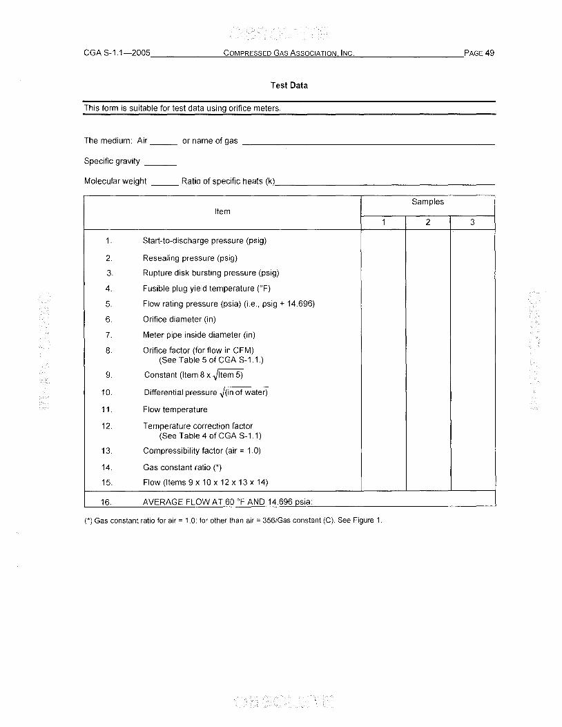
CGA S-1.1-2005 _______ C=O:.:.:M!...PR'-"E""S""S:.=E""'D....::G"-CA.:::s:...cA..!.::s""s""o""c"'-IA!..!.T.!-"IO<.!;N:..:..,.!.:.IN"",C,-,-. __________ ,PAGE 49
Test Data
This form is suitable for test data using orifice meters.
The medium: Air ___ or name of gas _______________________ _
Specific gravity __ _
Molecular weight ___ Ratio of specific heats (k) ___________________ _
Samples Item
1 2 3
1. Start-to-discharge pressure (psig)
2. Resealing pressure (psig)
3. Rupture disk bursting pressure (psig)
4. Fusible plug yield temperature (OF)
5. Flow rating pressure (psia) (i.e., psig + 14.696)
6. Orifice diameter (in)
7. Meter pipe inside diameter (in)
8. Orifice factor (for flow in CFM) (See Table 5 of CGA S-1.1.)
9. Constant (Item 8 x ~Item 5)
10. Differential pressure ~(in of water)
11. Flow temperature
12. Temperature correction factor (See Table 4 of CGA S-1.1)
13. Compressibility factor (air = 1.0)
14. Gas constant ratio (*)
15. Flow (Items 9 x 10 x 12 x 13 x 14)
16. AVERAGE FLOW AT 60 of AND 14.696 psia:
(*) Gas constant ratio for air = 1.0; for other than air = 356/Gas constant (e). See Figure 1.
Appendix B-Requalification procedures for eG-7 pressure relief valves (Normative)
Note shall be taken that not all pressure relief valves (CG-7) are designed to be requalified. For those pressure relief valves that are designed for requalification, the following nine-step procedure shall be followed:
1. The following data shall be recorded: pressure relief valve manufacturer, date of manufacture, minimum start-to-discharge pressure, and flow rating pressure. This data may be on the valve in a coded form and not obvious to the requalifier. Therefore, the requalifier shall have in his possession a copy of the latest pressure relief valve coded markings from the manufacturer(s) of the devices that are being requalified.
WARNING: Only trained personnel shall attempt to proceed with this test. When conducting pressure tests, only use inert gases (such as nitrogen) to pressurize the testing manifold. Operators shall use safety glasses and other related safety equipment as deemed necessary. Failure to comply with this warning can result in personal injury or death.
2. Install the pressure relief valve in a test manifold and immerse the pressure relief valve under water to a maximum of 4 in (102 mm).
3. Pressurize the pressure relief valve in accordance to the start-to-discharge method indicated in this standard (see 6.6.3). If bubbles are observed from the outlet of the pressure relief valve at less than 75% of the minimum cylinder test pressure the valve fails the test and shall be removed from service. If at any time during the start-to-discharge test bubble discharge is noted record the start-to-discharge pressure of the pressure relief valve and proceed to step 6.
4. If bubble discharge from the outlet of the pressure relief valve at 100% of the minimum cylinder test pressure is not observed, the pressure relief valve fails the test and shall be removed from service.
5. Once bubble discharge has occurred and the pressure recorded decrease the pressure on the manifold at a rate not exceeding 100 psi (690 kPa) per minute. Record the pressure at which the bubble discharge ceases. This is the resealing pressure of the pressure relief valve. Failure of bubble discharge to cease below the pressure in a normally charged cylinder at 130 OF (54.4 0c) indicates failure of the pressure relief valve. The valve shall be removed from service.
6. Discharge all pressure from the manifold and without cleaning, removing parts, or reconditioning, each pressure relief valve shall be subjected to an actual flow test at its flow rating pressure, wherein the amount of air or gas released by the pressure relief valve is measured. Failure to achieve the rated flow capacity results in failure of the test, and the pressure relief valve shall be removed from service. Pressure relief valves passing the flow test will then be retested in accordance with steps 2-6 after at least 1 hour following the flow test. There is no need to perform step 7 a second time. Such a test may be made by the manufacturer of the pressure relief valve or by a qualified test laboratory.
7. If all requirements have been achieved, the pressure relief valve shall be marked to identify the date of requalification and the identity of the company performing the requalification.
8. The records shall be signed and dated by the person performing the requalification. Records of the requalification of pressure relief devices shall be kept for a minimum of 6 years by the company performing the requalification.