CFM 56-7B AGB LH FWD Mount Damper Change Tool
16
CFM 56-7B AGB LH FWD Mount Damper Replacement Tool Internship Supervisor: Amine Rahoui Intern: Yassine Rayad
-
Upload
yassine-rayad -
Category
Documents
-
view
127 -
download
7
Transcript of CFM 56-7B AGB LH FWD Mount Damper Change Tool

CFM 56-7B AGB LH FWD Mount
Damper Replacement ToolInternship Supervisor: Amine Rahoui
Intern: Yassine Rayad

The problem at hand involves changing the dampers of the accessory gear box LH forward mount.
The ESM does not have a detailed procedure for this task that does not involve the removal and inspection of the AGB.
The goal of this project was to adapt an existing tool (used for the damper change on the CFM 56-3 engine).
Problem Definition

CFM56-7B
Engine

AGB LH FWD Mount
Environment

Dampers
These are the dampers that are required to be changed using the adapted tool.

In order to avoid having to remove and inspect the entire AGB module, the proposed solution involves supporting the AGB in the same position to facilitate the damper change.
The tool shall be fixed to the AGB LH FWD Mount and to the AGB itself.
Solution Overview

At this point it is important to note that in order to perform an accurate analysis of the required strength for the tool, we must have an accurately modeled environment.
This was not completely feasible as the environment was modeled from the ESM which does not provide all the necessary dimensions.
Despite the simplicity of the load case (static weight loading) the difficulty of modeling the environment as close to reality as possible made the project more complicated than it needed to be as many dimensions and distances had to measured physically on engines being maintained or repaired.
Approach

The geometry was modeled and assembled using Creo Parametric 2.0.
The assembly file was saved in the .igs and .stp format to allow access with other software.
The assembly was then imported into a Static Structural analysis block in ANSYS Workbench R14.5.
Approach (continued)

The modeled environment◦ The AGB LH FWD Mount
This is one of the most important parts of the environment and was modeled mostly from the ESM. Some dimensions such as the distance in between the two parts were measured physically on a few engines using a Caliper. This part supports the AGB from the top.
Approach (continued)

The modeled environment◦ The AGB Mount Link Assembly
This part consists of a link with three holes and three fitted bearings. It is used to link the AGB with the AGB LH FWD Mount. Since inspection of this part is required in the ESM, key dimensions are given and we were able to represent this part with better accuracy than the rest of the environment.
Approach (continued)
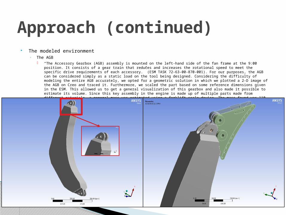
The modeled environment◦ The AGB
“The Accessory Gearbox (AGB) assembly is mounted on the left-hand side of the fan frame at the 9:00 position. It consists of a gear train that reduces and increases the rotational speed to meet the specific drive requirements of each accessory.” (ESM TASK 72-63-00-870-001). For our purposes, the AGB can be considered simply as a static load on the tool being designed. Considering the difficulty of modeling the entire AGB accurately, we opted for a geometric solution in which we plotted a 2-D image of the AGB on Creo and traced it. Furthermore, we scaled the part based on some reference dimensions given in the ESM. This allowed us to get a general visualization of this gearbox and also made it possible to estimate its volume. Since this key assembly in the engine is made up of multiple parts made from different materials, a general mass was estimated using a forklift scale device. The mass found was 110 kg.
Approach (continued)

The modeled tool◦ As can be seen in the figures below, the tool is attached to the AGB LH FWD Mount via the points
shown. It is important to note that for this solution, the modeled environment was simplified by omitting the bottom AGB mount. Therefore, the tool designed here is required to sustain a larger load than it would realistically be required to sustain. Additionally, we considered a factor of safety of 1.5 in the following static structural analysis. The stress and deformation results are shown in the following slide. Material selection is also dealt with in the following slides.
Solution
Attachment points

The mesh shown below is the final refined mesh used in the latest iteration of the analysis. Element sizes range from approximately 4-5 mm for the AGB mount and the tool to 10 mm for the AGB. As we can see in the Element Quality Metrics figure, the element quality is adequate and acceptable.
Mesh

Stress and Deformation◦ As can be seen in the figures below, the maximum stress experienced by the
tool under the static load previously described is 533.9 Mpa and occurs on the bolt that connects the tool to the AGB. The maximum deformation occurs at the same point with a value of 1.0278 mm. With these values, we are able to select the appropriate materials.
Results

The tool as modeled should only consist of one part and all the attaching bolts and screws. In order to address the 1.5 factor of safety, it was decided that the tool should be manufactured from Titanium as well as the bolt that connects the tool and AGB. The rest of the parts can be manufactured from Structural Steel. The following figure displays the overall factor of safety distribution throughout the tool. The minimum factor of safety which were able to obtain is 1.7419.
Material Selection

In conclusion, a tool for the replacement of dampers in the AGB LH FWD Mount for the -7B engine was adapted from an existing tool designed for the -3 engine.
The attachment points to the engine (flanges B4 and B5) via the AGB LH FWD Mount were modified to fit the -7B engine environment.
It is important to note that the reference dimensions for modeling the environment accurately were not all available in the ESM or the EIPC. Hence, certain geometric assumptions were made. It is safe to say that the model is close to real environment but there are some unverified dimensions.
I strongly recommend that the analysis be carried out again with an accurate weight for the AGB as well as a full model of the AGB mounts (top and bottom). I also recommend using the original part dimensions from the manufacturer for the AGB mounts, as the design/adaptation of the tool depends heavily on these dimensions.
Conclusion and Recommendations