CFD Vision 2030 CFD Study - HPC User · PDF fileCFD Vision 2030 CFD Study ... CFD Challenge...
28
CFD Vision 2030 CFD Study A Pathway to Revolutionary Computational Aeroscienes Presentation at 56 th HPC User Forum Norfolk, VA April 13 - 15, 2015 1 Mujeeb R. Malik Senior Scientist for Aerodynamics Technical Lead, Revolutionary Computational Aerosciences NASA Langley Research Center
Transcript of CFD Vision 2030 CFD Study - HPC User · PDF fileCFD Vision 2030 CFD Study ... CFD Challenge...

CFD Vision 2030 CFD StudyA Pathway to Revolutionary Computational Aeroscienes
Presentation at 56th HPC User Forum
Norfolk, VA
April 13-15, 2015
1
Mujeeb R. MalikSenior Scientist for Aerodynamics
Technical Lead, Revolutionary Computational AerosciencesNASA Langley Research Center
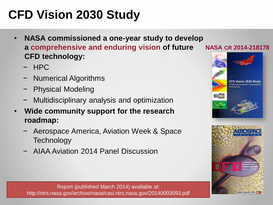
CFD Vision 2030 Study
• NASA commissioned a one-year study to develop
a comprehensive and enduring vision of future
CFD technology:
− HPC
− Numerical Algorithms
− Physical Modeling
− Multidisciplinary analysis and optimization
• Wide community support for the research
roadmap:
− Aerospace America, Aviation Week & Space
Technology
− AIAA Aviation 2014 Panel Discussion
NASA CR 2014-218178
Report (published March 2014) available at:
http://ntrs.nasa.gov/archive/nasa/casi.ntrs.nasa.gov/20140003093.pdf

Background - 1: CFD Impacts 3 NASA
Mission Directorates
• Aeronautics Research Mission Directorate (ARMD):
– It supports three of the ARMD strategic thrusts, and the associated
“outcomes”
– Plays an important role in subsonic and supersonic civil aircraft and
rotorcraft technology development
– Basic computational tool development
• OVERFLOW, CFL3D, ARC3D, Wind-US, Vulcan …
• FUN3D, USM3D, CART3D…
• Human Exploration and Operations (HEOMD):
– Development of Space Launch System, Orion
• Science (SMD):
– Planetary entry systems (MSL/Curiosity)
– Climate, weather, environment
CFD is a cross-cutting technology

Background - 2: CFD Impacts Commercial
Space Industry
4
• Using NASA’s FUN3D as primary CFD tool for:
− Falcon 1 ascent aero
− Falcon 9 ascent aero
− Lower speed Dragon reentry aero
• Full, detailed vehicle models, including up to 18 plumes
• Performing hundreds of simulations per vehicle across the flight envelope
• CFD predictions agree very well with all flight and wind tunnel data
• SpaceX developing combustion CFD for rocket engines using GPUs
− Chemistry-turbulence interaction using grid adaptation
Falcon 9
First Launch
June 4, 2010
Images and Information
Courtesy of SpaceX

High-Speed Wing
Design Cab Design
Engine/Airfram
e Integration
Inlet Design
Inlet Certification
Exhaust-
System Design
Cabin
Noise
Community
Noise
Wing-Body
Fairing Design
Vertical Tail
and Aft Body
Design
Design For
Stability &
Control
High-Lift
Wing Design
APU Inlet
And Ducting
ECS Inlet
DesignAPU and Propulsion
Fire Suppression
Nacelle Design
Thrust-Reverser
Design Design for FOD
Prevention
Aeroelastics
Substantial CFD Utilization Some CFD Utilization
Icing
Air-Data
System
Locatio
n
Vortex
Generators
Planform
Design
Buffet
Boundary
Reynolds-Number
Corrections
Flutter
Control-Surface
Failure Analysis
Wind-Tunnel
Corrections
Wing-Tip Design
Wing
Controls
Avionics Cooling
Interior
Air
Quality
Engine-Bay Thermal
Analysis
Limited CFD Utilization
Key Enablers Include High Performance Computing and
Physics-based Design/Analysis/Optimization
Courtesy of Boeing
Background - 3: CFD Impacts Aeronautical Industry

Background - 4: Impact on Aircraft Efficiency and
Wind Tunnel Testing
“Since the first generation of jet airliners, there has been about a 40% improvement in aerodynamic efficiency and a 40% improvement in engine efficiency … about half of that has come from CFD.”
(Robb Gregg, BCA Chief Aerodynamicist)
• Significant (almost 70%) decrease in wind-tunnel testing time since
1980s has reduced cost and enabled faster market readiness
• Reduction in testing time largely enabled by availability of mature and
‘calibrated’ advanced CFD

• CFD has drastically reduced testing for cruise design
− Attached flow, well predicted by current turbulence models
• Testing required for off-design (e.g., high-lift) conditions (for conventional configurations) and for innovative configurations, in general
− Flow separation is the key issue, as separation not well predicted by turbulence models
− First principles simulations a HPC challenge
• Flow physics challenge highlighted in the Malik-Bushnell study
− “Role of Computational Fluid Dynamics and Wind Tunnels in Aeronautics R&D,” NASA-TP-2012-217602
− Led to Revolutionary Computational Aerosciences (RCA) Initiative
Background – 5: CFD Challenge for Aeronautics
Inability to further reduce number of
tests due to deficiency in modeling
of turbulent flow physics

• Accurate, fast and robust computational tools can
fundamentally change the aerospace design space
• Improved simulation capabilities bring:− Superior/more capable designs
− Reduced development cycle time/cost/risk
− Scientific and industrial competitiveness
− Lead to innovation
“Discovery” by High Performance Computing
Decadal Survey of Civil Aeronautics (NAE):“…an important benefit of advances in physics-based analysis tools is the new technology and systems frontiers they open”
Background – 6: Potential of Advanced CFD

Vision 2030 Study Charter
• NASA commissioned a one-year study (completed in March 2014) to
develop a comprehensive and enduring vision of future CFD
technology and capabilities:
– “…provide a knowledge-based forecast of the future
computational capabilities required for turbulent, transitional,
and reacting flow simulations…”
– “…and to lay the foundation for the development of a future
framework/environment where physics-based, accurate
predictions of complex turbulent flows, including flow
separation, can be accomplished routinely and efficiently in
cooperation with other physics-based simulations to enable
multi-physics analysis and design.”

Juan AlonsoStanford University
David DarmofalMassachusetts Inst. Of
Technology
William GroppNational Center for
Supercomputing Applications
Elizabeth LuriePratt & Whitney – United
Technologies
Dimitri MavriplisUniversity of Wyoming
Jeffrey SlotnickPrincipal InvestigatorBoeing Research & [email protected]
Abdi Khodadoust
Project ManagerBoeing Research & [email protected]
Vision 2030 CFD Team Members
NASA Technical Monitor – Mujeeb Malik/Bil Kleb
Extended Vision 2030 Team:
• Joerg Gablonsky, Mori Mani, Robert Narducci, Philippe Spalart, and Venkat
Venkatakrishnan – The Boeing Company
• Robert Bush – Pratt & Whitney

Vision 2030 Overview
• Elements of the study effort:
– Define and develop CFD requirements
– Identify the most critical gaps and impediments
– Create the vision
– Develop and execute a community survey and technical workshop
to gain consensus and refine the vision
Input from Government, Academia and Industry
– Develop a detailed technology development roadmap to
• capture anticipated technology trends and future technological
challenges,
• guide investments for long-term research activities
• provide focus to the broader CFD community for future
research activities

Vision of CFD in 2030
Emphasis on physics-based, predictive modeling
Transition, turbulence, separation, chemically-reacting flows, radiation, heat
transfer, and constitutive models, among others
Management of errors and uncertainties
From physical modeling, mesh and discretization inadequacies, natural
variability (aleatory), lack of knowledge in the parameters of a particular fluid
flow problem (epistemic), etc.
A much higher degree of automation in all steps of the analysis
process
Geometry creation, meshing, large databases of simulation results, extraction
and understanding of the vast amounts of information generated with minimal
user intervention
Effective utilization of massively parallel, heterogeneous, and
fault-tolerant HPC architectures available in the 2030 time frame
Multiple memory hierarchies, latencies, bandwidths, etc.
Flexible use of HPC systems
Capability- and capacity-computing tasks in both industrial and research
environments
Seamless integration with multi-disciplinary analyses
High fidelity CFD tools, interfaces, coupling approaches, etc.

Findings
1. Investment in technology development for simulation-based analysis
and design has declined significantly in the last decade and must be
reinvigorated if substantial advances in simulation capability are to be
achieved.
2. High Performance Computing (HPC) hardware is progressing rapidly
– Many CFD codes and processes do not scale well on petaflops systems
– CFD codes achieve only 3-5% of peak theoretical machine performance
– NASA poorly prepared for exaflops (1018 flops) revolution
3. The accuracy of CFD in the aerospace design process is severely limited by the
inability to reliably predict turbulent flows with significant regions of separation
cruise point
normal
operational
range
borders of the
flight envelopeBuffet boundary
Maximum lift
High lift
Unsteady effects
cruise point
normal
operational
range
borders of the
flight envelopeBuffet boundary
Maximum lift
High lift
Unsteady effects
CFD accurate
only near
cruise point

Findings CONTINUED
4. Mesh generation and adaptivity continue to be significant bottlenecks
in the CFD workflow, and very little government investment has been
targeted in these areas
– Goal: Make grid generation invisible to the CFD analysis process
Robust and optimal mesh adaptation methods need to become the
norm
5. Algorithmic improvements will be required to enable future advances
in simulation capability
– Robust solution convergence for complex geometries/flows is lacking
– Improved scalability on current and emerging HPC hardware needed
– Develop “optimal” solvers, improve discretizations (e.g., high-order)
6. Managing the vast amounts of large-scale simulations data will
become increasingly complex due to changing HPC hardware
7. In order to enable multidisciplinary simulations, for both analysis and
design optimization purposes, several advances are required: CFD
solver robustness/automation, standards for coupling, computing and
propagating sensitivities and uncertainties

Recommendations
1. NASA should develop, fund and sustain a technology
development program for simulation-based analysis and
design. Success will require collaboration with experts in computer science,
mathematics, and other aerospace disciplines
2. NASA should develop and maintain an integrated simulation and software development infrastructure to enable rapid CFD technology maturation.
Maintain a world-class in-house simulation capability
– Critical for understanding principal technical issues, driving development of new techniques, and demonstrating capabilities
3. HPC systems should be made available and utilized for large-scale CFD development and testing.
Acquire HPC system access for both throughput (capacity) to support programs and development (capability)
– improved software development, implementation, and testing is needed
Leverage national HPC resources
Recommendations CONTINUED
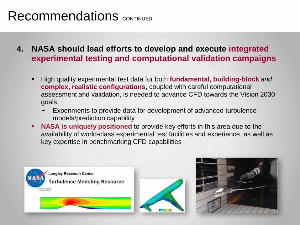
4. NASA should lead efforts to develop and execute integrated experimental testing and computational validation campaigns
High quality experimental test data for both fundamental, building-block and complex, realistic configurations, coupled with careful computational assessment and validation, is needed to advance CFD towards the Vision 2030 goals
− Experiments to provide data for development of advanced turbulence models/prediction capability
NASA is uniquely positioned to provide key efforts in this area due to the availability of world-class experimental test facilities and experience, as well as key expertise in benchmarking CFD capabilities

Recommendations CONTINUED
5. NASA should develop, foster, and leverage improved collaborations with key research partners across disciplines within the broader scientific and engineering communities
Emphasize funding in computer science and applied mathematics
Embrace and establish sponsored research institutes provides centralized development of cross-cutting disciplines.
CTR
6. NASA should attract world-class engineers and scientists.
Success in achieving the Vision 2030 CFD capabilities is highly dependent on obtaining, training, and nurturing a highly educated and effective workforce
– Expand fellowship programs in key computational areas
– Encourage and fund long-term visiting research programs

18
Notional Technology Roadmap
Visualization
Unsteady, complex geometry, separated flow at
flight Reynolds number (e.g., high lift)
2030202520202015
HPCCFD on Massively Parallel Systems
CFD on Revolutionary Systems
(Quantum, Bio, etc.)
TRL LOW
MEDIUM
HIGH
PETASCALE
Demonstrate implementation of CFD
algorithms for extreme parallelism in
NASA CFD codes (e.g., FUN3D)
EXASCALE
Technology Milestone
Demonstrate efficiently scaled
CFD simulation capability on an
exascale system
30 exaFLOPS, unsteady,
maneuvering flight, full engine
simulation (with combustion)
Physical Modeling
RANS
Hybrid RANS/LES
LES
Improved RST models
in CFD codes
Technology Demonstration
Algorithms
Convergence/Robustness
Uncertainty Quantification (UQ)
Production scalable
entropy-stable solvers
Characterization of UQ in aerospace
Highly accurate RST models for flow separation
Large scale stochastic capabilities in CFD
Knowledge ExtractionOn demand analysis/visualization of a
10B point unsteady CFD simulation
MDAO
Define standard for coupling
to other disciplines
High fidelity coupling
techniques/frameworks
Incorporation of UQ for MDAO
UQ-Enabled MDAO
Integrated transition
prediction
Decision Gate
YES
NO
NO
Scalable optimal solvers
YES
NODemonstrate solution of a
representative model problem
Robust CFD for
complex MDAs
Automated robust solvers
Reliable error estimates in CFD codes
MDAO simulation of an entire
aircraft (e.g., aero-acoustics)
On demand analysis/visualization of a
100B point unsteady CFD simulation
Creation of real-time multi-fidelity database: 1000 unsteady CFD
simulations plus test data with complete UQ of all data sources
WMLES/WRLES for complex 3D flows at appropriate Re
Integrated Databases
Simplified data
representation
Geometry and Grid
Generation
Fixed Grid
Adaptive Grid
Tighter CAD couplingLarge scale parallel
mesh generationAutomated in-situ mesh
with adaptive control
Production AMR in CFD codes
Uncertainty propagation
capabilities in CFD
Grid convergence for a
complete configuration
Multi-regime
turbulence-chemistry
interaction model
Chemical kinetics
in LESChemical kinetics
calculation speedupCombustion
Unsteady, 3D geometry, separated flow
(e.g., rotating turbomachinery with reactions)
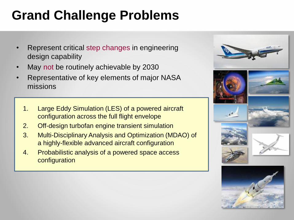
Grand Challenge Problems
• Represent critical step changes in engineering
design capability
• May not be routinely achievable by 2030
• Representative of key elements of major NASA
missions
1. Large Eddy Simulation (LES) of a powered aircraft
configuration across the full flight envelope
2. Off-design turbofan engine transient simulation
3. Multi-Disciplinary Analysis and Optimization (MDAO) of
a highly-flexible advanced aircraft configuration
4. Probabilistic analysis of a powered space access
configuration

LES of a Powered Aircraft Configuration Across
the Full Flight Envelope
Assess the ability to use CFD over the entire flight envelope, including dynamic maneuvers
Assess the ability of CFD to accurately predict separated turbulent flows Monitor increasing LES region for hybrid RANS-
LES simulations
Evaluate success of wall-modeled LES (WMLES)
Determine future feasibility of wall-resolved LES (WRLES)
Assess the ability to model or simulate transition effects
Enable future reductions in wind tunnel testing

Comparison of HPC at NASA and DoE
DOE and NASA HPC Systems
Among the Top 100 Worldwide
Machine / Agency Speed
2. Titan 3.3
3. Sequoia 3.3
5. Mira 1.6
9. Vulcan 0.8
11. Pleiades 1.0
NASA
1 system, 211 thousand cores
capable of 5.3 petaflops.
Department of Energy
Several systems.
Hierarchical Approach at DOE“Capability” Computing
“Capacity”
Computing
Titan, Oak Ridge
Pleiades Divided Among More than a
Hundred Users, generally allowing
“capacity” computing only (Typical
simulation: 1000’s of cores)
Pleiades,
NASA Ames
HPC Resource Allocation to NASA
Mission Directorates

Simulation-Based Airframe Noise Predictions(Model Scale Results) – Example of “Hybrid RANS/LES”
Simulation Characteristics
• Simulated geometry As‒built 18% scale high-fidelity Gulfstream model
Re = 3.47 x 10⁶ based on MAC
Finest resolution: 3x10⁹ cells, 4000 cores, 1x10⁶ CPU hours (NASA
Pleiades)
• Baseline configurations 39º flap deflection, main gear removed
39º flap deflection, main gear deployed
• Quiet configurations Various flap tip noise reduction concepts (main gear off)
Treatment applied to flap tips and main landing gear
Accomplishments
• Core objectives met Predicted farfield noise for baseline and quiet configurations in good
agreement with measurements obtained in the LaRC 14x22 wind tunnel
Established computational simulations as an accurate predictive tool
Paved the way for application to full-scale
Flap 39º, main gear on configuration
QuietBaseline
Simulated instantaneous pressure field for baseline and quiet configurations
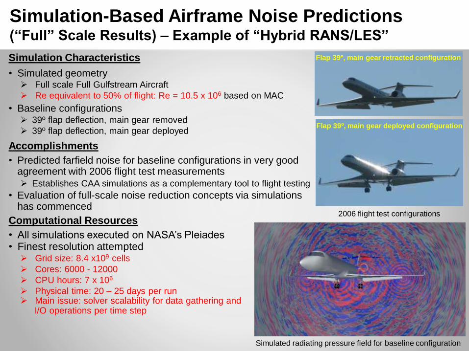
Simulation Characteristics
• Simulated geometry Full scale Full Gulfstream Aircraft
Re equivalent to 50% of flight: Re = 10.5 x 10⁶ based on MAC
• Baseline configurations 39º flap deflection, main gear removed
39º flap deflection, main gear deployed
Accomplishments
• Predicted farfield noise for baseline configurations in very good agreement with 2006 flight test measurements Establishes CAA simulations as a complementary tool to flight testing
• Evaluation of full-scale noise reduction concepts via simulations has commenced
Computational Resources
• All simulations executed on NASA’s Pleiades• Finest resolution attempted Grid size: 8.4 x10⁹ cells
Cores: 6000 - 12000
CPU hours: 7 x 10⁶
Physical time: 20 – 25 days per run Main issue: solver scalability for data gathering and
I/O operations per time step
Flap 39º, main gear deployed configuration
Flap 39º, main gear retracted configuration
Simulated radiating pressure field for baseline configuration
Simulation-Based Airframe Noise Predictions(“Full” Scale Results) – Example of “Hybrid RANS/LES”
2006 flight test configurations

Cost Estimates for Full Aircraft LES
• Pure LES intractable due to range of scales in Boundary Layer– Large aircraft flight Reynolds number ~ 50M
– LES* (explicit in time) : grid resolution ~ Re13/7, FLOPS ~ Re2.5
• Resolved to y+ = 1
– Wall Modeled LES* (explicit): grid res. ~ Re, FLOPS ~ Re1.3
• Resolved to y+ = 100
• Estimates for WMLES for simple wing (AR=10) at flight Re– 1011 to 1012 grid points, 500 Pflops for 24hr turnaround
– Simulating transition adds factor of 10 to 100
– Feasible on Exaflop machine
• Full aircraft WMLES not possible on exascale machine
[*]Choi and Moin, “Grid point requirements for LES: Chapman’s
estimates revisited”, Phys. Fluids, 24, 011702 (2012)

CFD Efficiency Enhancement
• Orders of magnitude reduction in time to solution is a critical need for analysis and design
− Unsteady flow computations for complex configurations
− Use of high-fidelity CFD in MDAO
• Approaches for enhancing CFD efficiency− Effective utilization of existing HPC hardware
Current CFD codes run at 3-5% of machine peak performance
There is potential for 10x improvement
2013 Gordon Bell Prize awarded to ETH team that achieved 55% of theoretical peak performance on IBM Blue Gene
− Exploitation of future HPC hardware
CFD code scalability for exascale architecture
GPUs for desktop engineering work stations
− Grid adaptation (e.g., adjoint-based)
Promises significant reduction in grid requirement
Automatic viscous grid adaptation remains a challenge
− High-order methods
Significant potential to speed-up unsteady flow simulations (HO accuracy allows coarser grid, both spatially and temporally)
Need efficient solvers to overcome numerical stiffness
ETH Team Achieved:
55% of theoretical peak
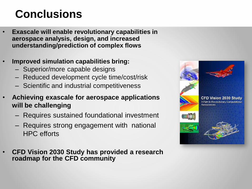
Conclusions
• Exascale will enable revolutionary capabilities in aerospace analysis, design, and increased understanding/prediction of complex flows
• Improved simulation capabilities bring:
– Superior/more capable designs
– Reduced development cycle time/cost/risk
– Scientific and industrial competitiveness
• Achieving exascale for aerospace applications
will be challenging
– Requires sustained foundational investment
– Requires strong engagement with national
HPC efforts
• CFD Vision 2030 Study has provided a research roadmap for the CFD community


• Wall-modeled LES (WMLES) cost estimates
– Using explicit, 2nd order accurate finite volume/difference
– Unit aspect ratio wing, Mach 0.2 flow
• Comparison to current HPC #1 system: Tianhe-2
– 55 PFLOP/s theoretical peak; 34 PFLOP/s on Linpack benchmark
– WMLES Re=1e6 feasible today on leadership class machines
• 2030 HPC system estimate
– 30 ExaFLOP/s theoretical peak
– WMLES Re=1e8 feasible on 2030 HPC
– Wall-resolved LES not possible on 2030 HPC
• Comments:
– These are capability computations (maxing out leadership HPC)
– Simple geometry (unit aspect ratio; isolated, clean wing; etc.)
– Algorithmic advances critical for grand challenge problems (hardware
advancements alone not sufficient)
Case Study: LES Cost Estimates
24 hour turn-
around time