CFD Simulation Results from Co-firing of Coal and ... · CFD simulation results: Summary Torrefied...
20
Perttu Jukola & Marko Huttunen / VTT Technical Research Centre of Finland IFRF, Finnish-Swedish Flame Days, 17.-18.04.2013, Jyväskylä, Finland CFD Simulation of Biofuel and Coal Co-Combustion in a Pulverized Coal Fired Furnace
Transcript of CFD Simulation Results from Co-firing of Coal and ... · CFD simulation results: Summary Torrefied...

Perttu Jukola & Marko Huttunen / VTT Technical Research Centre of Finland
IFRF, Finnish-Swedish Flame Days, 17.-18.04.2013, Jyväskylä, Finland
CFD Simulation of Biofuel and Coal Co-Combustion
in a Pulverized Coal Fired Furnace

2
CFD simulation of biofuel and coal co-combustion: Scope
CFD applied to simulate of co-combustion in a (normally)
pulverized coal fired unit Main fuel: Russian hard coal
Supplementary fuel 1: Torrefied biomass (TF)
TF shares of to 30 wt-% and 50 wt-% considered
24 % and 43 % on energy basis
Supplementary fuel 2: Pyrolysis oil (bio-oil, BO)
BO share of 25 % by energy
Focus: combustion / furnace process
Ignored: biofuel availibility, storage etc.
3
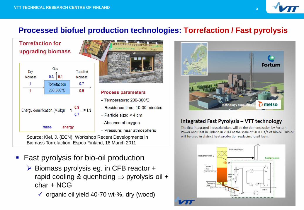
Fast pyrolysis for bio-oil production
Biomass pyrolysis eg. in CFB reactor +
rapid cooling & quenhcing pyrolysis oil +
char + NCG
organic oil yield 40-70 wt-%, dry (wood)
Processed biofuel production technologies: Torrefaction / Fast pyrolysis
Source: Kiel, J. (ECN), Workshop Recent Developments in
Biomass Torrefaction, Espoo Finland, 18 March 2011
4
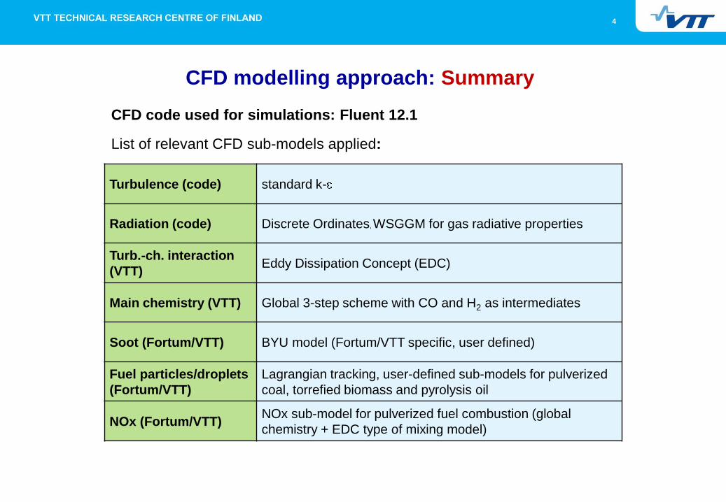
CFD modelling approach: Summary
Turbulence (code) standard k-
Radiation (code) Discrete Ordinates, WSGGM for gas radiative properties
Turb.-ch. interaction
(VTT) Eddy Dissipation Concept (EDC)
Main chemistry (VTT) Global 3-step scheme with CO and H2 as intermediates
Soot (Fortum/VTT) BYU model (Fortum/VTT specific, user defined)
Fuel particles/droplets
(Fortum/VTT)
Lagrangian tracking, user-defined sub-models for pulverized
coal, torrefied biomass and pyrolysis oil
NOx (Fortum/VTT) NOx sub-model for pulverized fuel combustion (global
chemistry + EDC type of mixing model)
CFD code used for simulations: Fluent 12.1
List of relevant CFD sub-models applied:
5
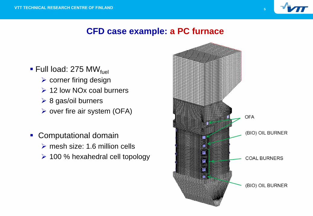
Full load: 275 MWfuel
corner firing design
12 low NOx coal burners
8 gas/oil burners
over fire air system (OFA)
Computational domain
mesh size: 1.6 million cells
100 % hexahedral cell topology
CFD case example: a PC furnace

6
Fuels in co-combustion
Russian hard coal
Torrefied biomass
Pyrolysis oil (bio-oil)
Basic assumption: coal and TF are milled together
in existing coal mills
7
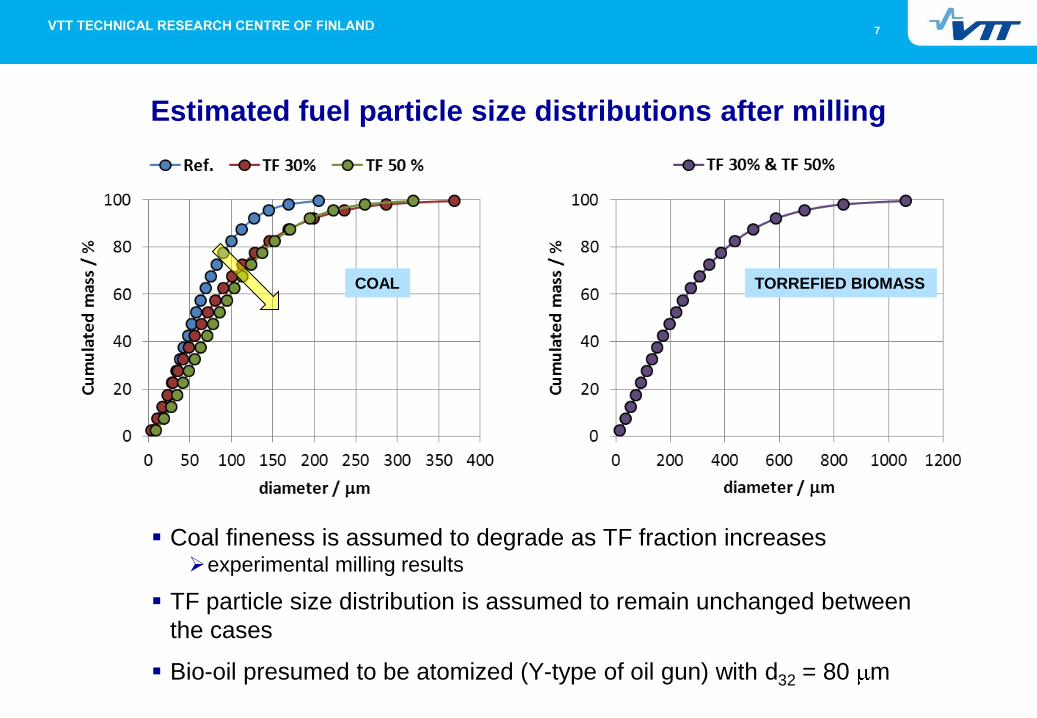
Estimated fuel particle size distributions after milling
Coal fineness is assumed to degrade as TF fraction increases experimental milling results
TF particle size distribution is assumed to remain unchanged between
the cases
Bio-oil presumed to be atomized (Y-type of oil gun) with d32 = 80 m
COAL TORREFIED BIOMASS
8
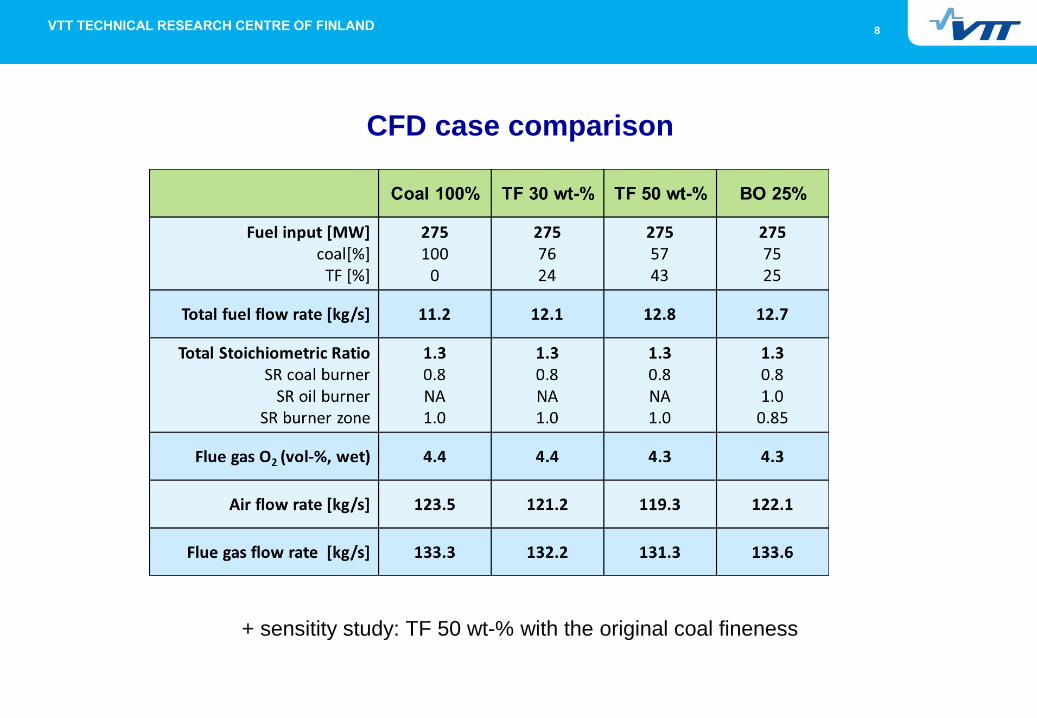
CFD case comparison
+ sensitity study: TF 50 wt-% with the original coal fineness
9
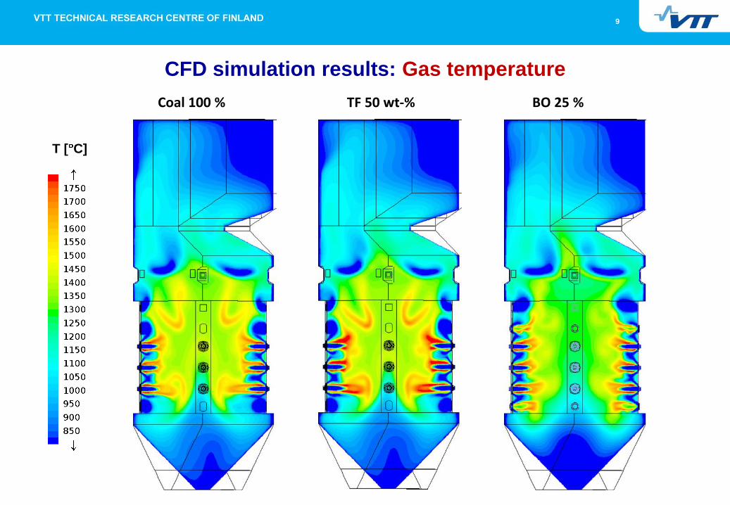
CFD simulation results: Gas temperature
Coal 100 % TF 50 wt-% BO 25 %
T [ C]

10
CFD simulation results: FEGT & Heat transfer
11
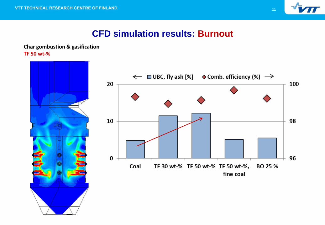
CFD simulation results: Burnout
Char gombustion & gasification TF 50 wt-%
12
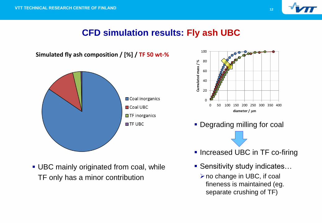
Degrading milling for coal
Increased UBC in TF co-firing
Sensitivity study indicates…
no change in UBC, if coal
fineness is maintained (eg.
separate crushing of TF)
CFD simulation results: Fly ash UBC
Simulated fly ash composition / [%] / TF 50 wt-%
UBC mainly originated from coal, while
TF only has a minor contribution

13
CFD simulation results: CO concentration
Coal 100 % TF 50 wt-% BO 25 % SR bzone = 1.0 SR bzone = 1.0 SR bzone = 0.85
CO [vol-%]

14
CFD simulation results: CO at nose and domain exit

15
CFD simulation results: NO concentration
Coal 100 % TF 50 wt-% BO 25 %
NO [ppm]
16
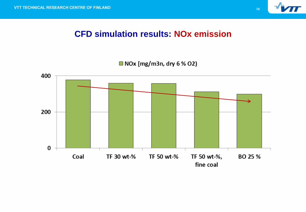
CFD simulation results: NOx emission
17
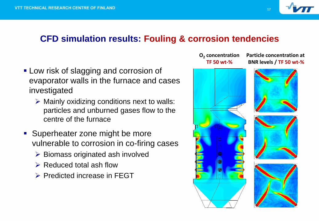
CFD simulation results: Fouling & corrosion tendencies
Low risk of slagging and corrosion of
evaporator walls in the furnace and cases
investigated
Mainly oxidizing conditions next to walls:
particles and unburned gases flow to the
centre of the furnace
Superheater zone might be more
vulnerable to corrosion in co-firing cases
Biomass originated ash involved
Reduced total ash flow
Predicted increase in FEGT
O2 concentration TF 50 wt-%
Particle concentration at BNR levels / TF 50 wt-%
18
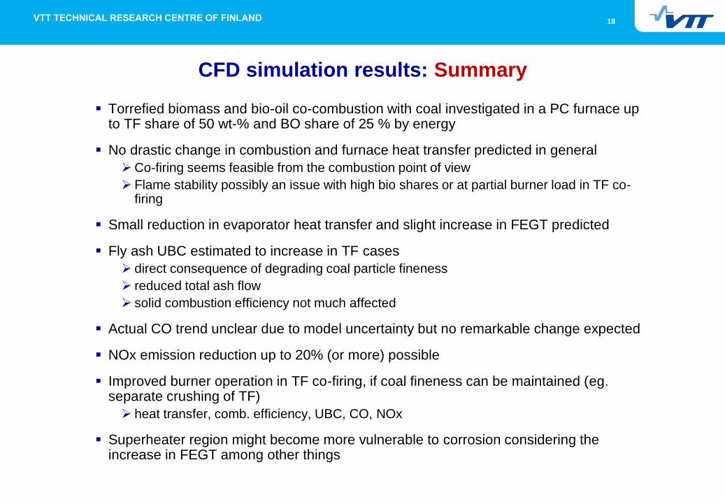
CFD simulation results: Summary
Torrefied biomass and bio-oil co-combustion with coal investigated in a PC furnace up to TF share of 50 wt-% and BO share of 25 % by energy
No drastic change in combustion and furnace heat transfer predicted in general
Co-firing seems feasible from the combustion point of view
Flame stability possibly an issue with high bio shares or at partial burner load in TF co-firing
Small reduction in evaporator heat transfer and slight increase in FEGT predicted
Fly ash UBC estimated to increase in TF cases
direct consequence of degrading coal particle fineness
reduced total ash flow
solid combustion efficiency not much affected
Actual CO trend unclear due to model uncertainty but no remarkable change expected
NOx emission reduction up to 20% (or more) possible
Improved burner operation in TF co-firing, if coal fineness can be maintained (eg. separate crushing of TF)
heat transfer, comb. efficiency, UBC, CO, NOx
Superheater region might become more vulnerable to corrosion considering the increase in FEGT among other things
19
Acknowledgements
Work was done as a part of the Torrefaction project in the Tekes Biorefine
technology programme
Funding of Tekes, Fortum Power and Heat Oy, Helsingin Energia, Metso
Power Oy, Metsä Fibre Oy, Pohjolan Voima Oy, UPM-Kymmene Oy, Vapo
Oy and VTT is gratefully acknowledged
Contact information
Perttu Jukola, Senior Scientist, VTT Technical Research Centre of
Finland, [email protected], +358 20 7225098
Marko Huttunen, Senior Scientist, VTT Technical Research Centre of
Finland, [email protected], +358 20 7225053

20
VTT creates business from technology