CFD and Thermo-Fluid Systems Modeling for Underhood ... · CFD and Thermo-Fluid Systems Modeling...
15
CFD and Thermo-Fluid Systems Modeling for Underhood Thermal Analysis Tanju Sofu, Jimmy Chang, John Hull Argonne National Laboratory Heavy Vehicle Systems Review April 19, 2006
-
Upload
trankhuong -
Category
Documents
-
view
230 -
download
0
Transcript of CFD and Thermo-Fluid Systems Modeling for Underhood ... · CFD and Thermo-Fluid Systems Modeling...

CFD and Thermo-Fluid Systems Modeling for Underhood Thermal Analysis
Tanju Sofu, Jimmy Chang, John Hull
Argonne National Laboratory
Heavy Vehicle Systems Review
April 19, 2006
Motivation
¢ An optimal design of vehicle thermal system is important for energy efficiency – Less than one-third of the total fuel energy provides useful
mechanical work – Remainder is lost through the exhaust system and heat rejection
¢ Determination of accurate temperature distributions in an engine is critical to achieve fuel efficiencies through cooling system optimization and radiator size reduction
¢ A predictive analytical capability can help redesign underhood configuration while meeting new energy efficiency and emissions requirements – Shorten component design and test cycles using a validated high-
fidelity but also a practical simulation tool
2

Objectives
¢ Address unique heavy-vehicle underhood thermal control challenges to improve energy efficiency – An integrated analysis approach to fully characterize thermal-flow
conditions in the underhood compartment of heavy vehicles – Combined use of 3-D Computational Fluid Dynamics (CFD) and 1-D
thermo-fluid systems models ¢ Specific focus on issues related to EPA emission regulations that require
redesign of underhood compartments – Emission control technologies like cooled EGR and after-treatment
devices increase engine heat rejection to both coolant and air ¢ Validation of integrated analysis approach via collaborations with Caterpillar
and Cummins – Two separate engine configurations and a range of operating conditions
3
– Evaluate the effect of cooling system and ventilation air flow on heat rejection and component temperatures

Modeling Approach
¢ Both CFD and thermo-fluid systems models have inherent limitations – CFD is computationally prohibitive for simulations of the entire system – Systems models oversimplify multi-dimensional flow and heat transfer
¢ Combined use of CFD and system models offers unique advantages – System model accounts for thermal energy balance and heat
distribution inside the engine through 1-D network of flow loops– CFD model addresses multi-dimensional flow and heat transfer
wherever needed– Reduced input data requirements: Combined model needs basic
ambient conditions and component performance curves – Data exchange between 1-D and 3-D models for flow splits, heat-fluxes,
and surface temperatures
4
Underhood CFD Model
¢ Analysis of underhood ventilation air flow and temperatures require multidimensional CFD techniques – Model development generally starts with the CAD data of the underhood
compartment – Various commercial CFD software can be used to generate unstructured
mesh for the complex geometry with selective grid refinement • STAR-CD and FLUENT are used in ANL efforts for projects with
Caterpillar and Cummins ¢ Wide range of turbulence model and boundary condition options are
assessed and “best practice guidelines” established – Reynolds-Averaged Navier Stokes (RANS) turbulence models provide
reasonable accuracy with practical computational requirements – Influence of ambient conditions is best captured by modeling beyond just
5
the underhood compartment
6
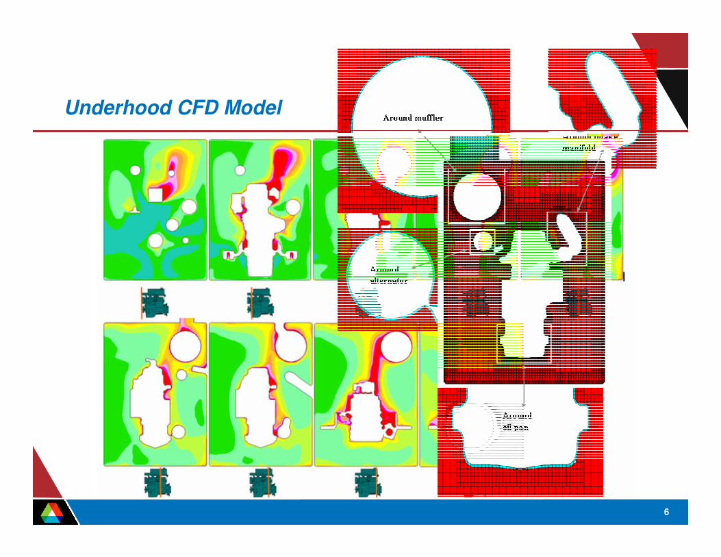
Underhood CFD Model

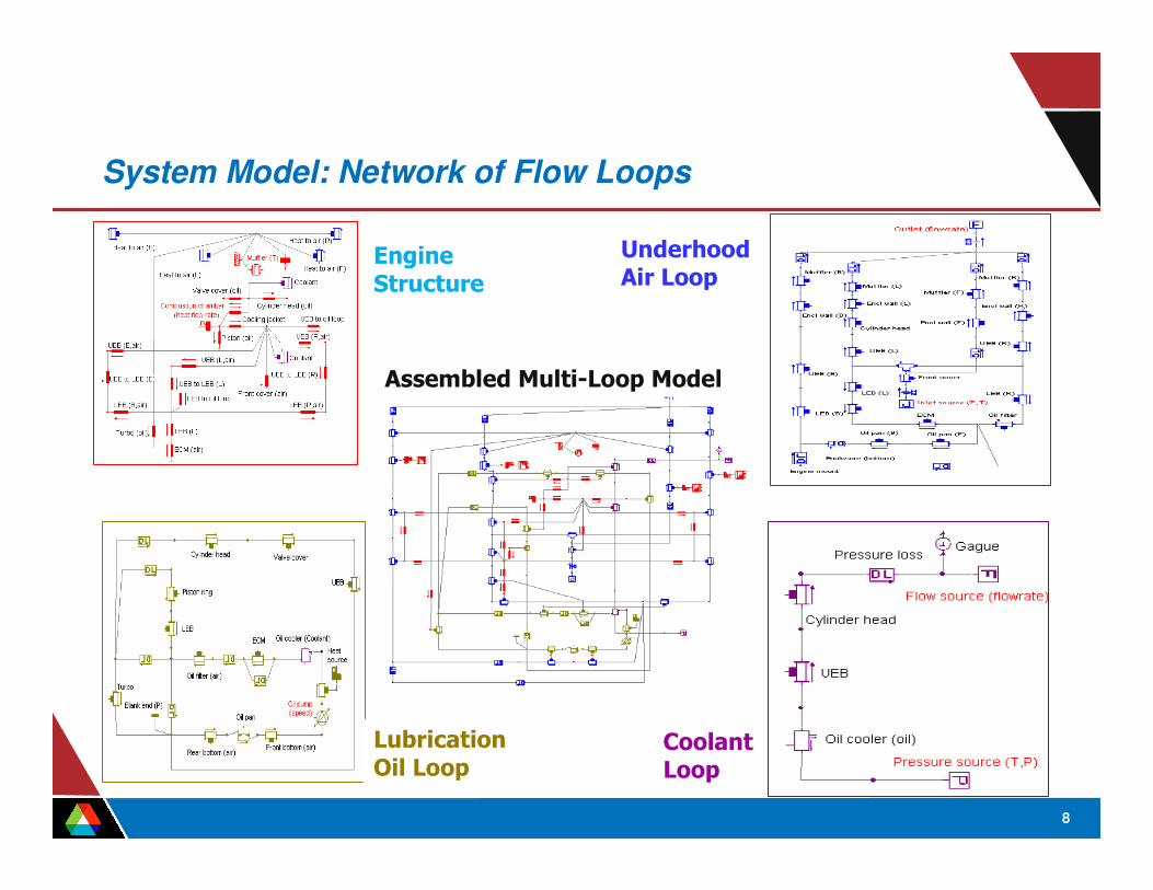
System Model: Network of Flow Loops
¢ 1-D representation of engine internal flow loops combined with a lumped-parameter approach to characterize the thermal interactions between them through the engine structure as the major conduction paths – Simplifies the complex engine system by discretization based on known
heat transfer paths under equilibrium conditions – Predicts the complete thermal system performance and calculates thermal
energy balance ¢ Commercial software FLOWMASTER for solution of analytical equations of
mass, momentum, and energy in reduced dimensions combined with empirical correlations for component behavior (pumps, valves, heat exchangers…)
¢ Analyze interactions of the engine with the coolant, oil, and ventilation air loops – Heat generated from combustion is considered to be transferred to various
discrete component surfaces (e.g., cylinder head, valve cover, front cover, engine block, cylinder head, ECM, etc.) through specified conduction paths
7
8
AirLoop
Lubrication
OilLoop Coolant
AssembledMulti-LoopModel
System Model: Network of Flow Loops
Engine Underh doo
St trucure
Loop

9
Integrated Underhood System Simulations
¢ Engine system model requires flow rates and inlet temperatures as boundary conditions for air, oil, and coolant loops – Accounts for cooling system response and thermal energy balance – Predicts heat rejection to air via engine structure and other heat generating
components ¢ CFD model use system model predictions as
surface heat flux boundary conditions for various engine components – Calculates underhood air flow field and
temperatures– CFD results are “reduced” to provide the
system model with data on flow splits andheat transfer coefficients
¢ An iterative process between the two models is needed to assure consistent solutions – Convergence between 1-D and 3-D solutions
is established after 6-7 sequential runs

Summary of Caterpillar CRADA
¢ Thermal analysis of an off-road machine engine with unique underhood thermal challenges – High auxiliary loads, no ram air – Divided engine and cooling system compartments
¢ Maintaining acceptable underhood temperatures in a well-sealed engine enclosure is important for component performance – assessment of component temperatures is an important element of
design cycle – a predictive analytical capability is needed to identify hot-spots
¢ As part of a CRADA, experiments are conducted at Caterpillar to study the effects of ventilation on heat rejection in a prototypical test-rig
¢ An integrated 1-D and 3-D model of the test rig is built at ANL to predict component temperatures for various air inlet locations and flow rates
10
– Good agreement with experiments for all inlet configurations and flow rates

closu
rewall
: exhau
stsid
e
Enclosu
rewall
: front
Oil pan
: front
Oil pan
: back
Front C
over
ECM(E
ngine Side)
ECM(A
irSide)
Oil filte
r
Cylinder
block: fro
nt
Cylinder
block: inta
kesid
e
linder
block: ex
haust
side
Cylinder
block: bac
k
Engine block: fro
nt
Engine block: intak
e side
ngine block: ex
haust
side
Engine block: bac
k
ylinder
head (va
lveco
ver)
Airat
Front Plat
e Area
Airat
ECMAre
a
Airat
Engine - Inta
ke-S
ide
Airat
Engine - Exh
aust-
Side
Airat
Enclosu
reOut
let
Wate
r To Engine
Wate
r From
Engine
Oil To Cooler
Oil Fro
mCooler
Oil To Bea
rings
Oil Sump
E
Nor
mal
ized
Tem
pera
ture
s(%
of m
axim
um te
mp.
)
Nor
mal
ized
Tem
pera
ture
s(%
of m
axim
um te
mp.
)
Summary of Caterpillar CRADA
Surface Temperatures--Front Inlet
30
40
50
60
70
80
90
100 CAT
ANL Fluid Temperatures--Front Inlet
20
30
40
50
60
70
80
90
100 CAT
ANL
11
n Cy E C

Scope of Cummins CRADA
¢ New project on diesel engine thermal analysis, initiated in February 2006 – Address design challenges related to emission control technologies
needed to meet the new diesel engine emission requirements – Help optimize cooling system size while meeting the new emission
requirements and cooling specifications ¢ An extension of integrated analysis approach to predict underhood flow
field and temperatures for a conventional truck with diesel engine – Determine underhood flow paths and component surface
temperatures– Predict hot spots and air-intake/cooling-fan air recirculation risks
¢ Cummins provide technical data needed for the model development and analysis, and perform thermal performance tests needed for validation – Benefits to a large spectrum of manufacturing community
12

Scope of Cummins CRADA
¢ An opportunity to understand the effect of EGR and after-treatment devices on diesel engine thermal performance – Higher engine heat rejection to both coolant and ventilation air – Higher underhood temperatures with potential hot spots
¢ Significant modifications in cooling system design – Additional models for radiator, condenser and
the heat-exchangers for turbo-charger andEGR-cooler are needed
• In current model these components areincluded as heat sinks with specified flowrate and temperature
– Corresponding component models for fan,pumps, compressor, thermostat and valvesare also needed for a complete coolingsystem model
13
Conclusions
¢ An optimal design of vehicle thermal system is essential for energy efficiency since most of total fuel energy is thermally wasted – Significant fuel efficiencies can be expected from optimization of cooling
system and reductions in radiator size through simulations ¢ A novel methodology developed to determine the ventilation air flow needs in
an engine enclosure and its effect on the thermal balance – An integrated analysis capability that needs only the basic
ambient/operating conditions and component performance curves– Applicable to a spectrum of heavy-vehicle underhood thermal analysis
¢ Initial assessments using data from Caterpillar tests – CFD for 3-D flow field and the rate of heat transfer between engine and air – Systems model to determine temperature distributions in engine structure
and components, coolant, lubrication oil loop, and ventilation air loops
14
– Good agreements with experiments for a range of configurations/flow rates
Future Work
¢ A new project to extend the integrated analysis approach to predict underhood flow field and temperatures for a conventional truck with diesel engine as part of a new CRADA with Cummins – Development of additional models for cooling system simulation – Address specific thermal-control challenges related to use of EGR
and after-treatment devices ¢ Opportunities with truck manufacturers to further test the models for
realistic underhood configurations (Cummins project will likely involve an OEM)
¢ Opportunities for integration with powertrain system analysis software – Account for overall (thermal and mechanical) energy balance – Quantify fuel economy and performance for warm-up, idle, cruise and
heavy-load conditions
15
– Simulate the effect of exhaust back-pressure on engine performance, torque and fuel consumption, etc.