CFD Analysis of a Gasoline Engine Exhaust Pipe · PDF filePage 2 of 7 Citation: Xu P, Jiang H,...
7
Research Article Open Access Xu et al., J Appl Mech Eng 2016, 5:2 DOI: 10.4172/2168-9873.1000198 Research Article Open Access Journal of Applied Mechanical Engineering J o u r n a l o f A p p li e d M e c h a n i c a l E n g i n e e r i n g ISSN: 2168-9873 Volume 5 • Issue 2 • 1000198 J Appl Mech Eng ISSN:2168-9873 JAME, an open access journal CFD Analysis of a Gasoline Engine Exhaust Pipe Pengyun Xu*, Haiyong Jiang and Xiaoshun Zhao Mechanical and Electronical Engineering College, Agriculture University of Hebei, Baoding 071001, P.R. China *Corresponding author: Pengyun Xu, Mechanical and Electronical Engineering College, Agriculture University of Hebei, Baoding 071001, PR China, Tel: +86-0312- 7526455; E-mail: [email protected] Received January 07, 2016; Accepted February 16, 2016; Published February 19, 2016 Citation: Xu P, Jiang H, Zhao X (2016) CFD Analysis of a Gasoline Engine Exhaust Pipe. J Appl Mech Eng 5:198. doi:10.4172/2168-9873.1000198 Copyright: © 2016 Xu P, et al. This is an open-access article distributed under the terms of the Creative Commons Attribution License, which permits unrestricted use, distribution, and reproduction in any medium, provided the original author and source are credited. Abstract The exhaust pipe is an important part of gasoline engine. Its structure and performance have a direct impact on the engine power, economy and emissions, and it is one of the key technologies of multi valve engine development. In or-der to test the theoretical design of a 1.5 L gasoline engine exhaust pipe, Solidworks Flow simulation was used to analyze the exhaust pipe. Pressure and velocity of the position near the three-way catalytic converter and the oxygen sensor were selective analyzed. CFD Simulation results show that the internal flow is laminar flow state, and the sensor position is reasonable. The design is reasonable, and can achieve the design goal. Keywords: Exhaust pipe; Catalytic converter; Carrier component; Fluid uniformity; CFD analysis Introduction e exhaust pipe is an important part of gasoline engine. It connects all parts of the automobile exhaust system, and prevent the leakage of waste gas. Its structure and performance have a direct impact on the engine power, economy and emissions, and it is one of the key technologies of multi valve engine development. Automobile exhaust pipe is a space curved surface geometry, it has a certain difficult to manufacture, and the exhaust pipe is worked in a bad condition, and some problems will occur in the process of production and use. e traditional design method of the exhaust pipe is in steady flow test stand experiments, to obtain or test shape parameter, this method takes long time and cost. However, using computer fluid analysis technology (CFD), it is convenient and intuitive to analyze the three-dimensional model of the exhaust pipe, the analysis process is visual, and easy to adjust the parameters, the analysis results are intuitive, determine whether the structure meets the design requirements quickly. In this paper, SolidWorks Flow Simulation is used to simulate the structure of a certain type of engine. Pressure and velocity of the position near the three way catalytic convert-er and the oxygen sensor were selective analyzed. e design goals are verified by simulation analysis (CFD) results. In order to reduce the concentration of CO, NOx and CxHy in the exhaust gas, there are (mostly) two catalytic converters installed in the exhaust pipe system. e crucial quantity to control the efficiency of a catalytic converter is the temperature in the catalytic converter. Due to this reason, one is interested in how to ensure a sufficient high temperature in the catalytic converters in a short time aſter the engine start. A special method of heating aſter the engine start is the combustion of unburnt gas in the catalytic converters. Modern cars can control the ratio of oxygen and fuel in the combustion chamber of the engine. By choosing a ratio with more fuel and less oxygen some unburnt fuel gets to the catalytic converters and can be used there for an exothermic reaction. In order to test the theoretical design of a 1.5 L gasoline engine exhaust pipe, carrying out a natural experiment in respect gas flow hydrodynamics. To estimate the spectrum of possible technological innovations in the existing struc-ture expedient, first carry out numerical simulations using fluid dynamics soſtware packages solidworks flow simula-tion. is paper presents the numerical simulation of classical structure of exhaust pipe; the results are compared with the calculation for the case of a conical nozzle on the exhaust pipe [1-5]. Material and Methods e calculation was carried out in gas dynamics soſtware package Solidworks Cosmos FloWorks, which uses a finite volume method, the movement of the fluid is modeled by the Navier Stokes equations, the Reynolds averaged. eir closures are used for the transport equation and its kinetic energy dissipation within the k-ε turbulence model. During the calculation was the condition of the grid and the iterative convergence, which were determined by the self-similarity of the final result of the number of cells and iterations. Calculation of the motion of particles in the flow was conducted under the following assumptions: • Uniform air and standard atmospheric pressure; • e particles have a spherical shape; • e drag coefficient of the particle is calculated by Henderson’s equation; A series of pertinent indoor and outdoor experiments are carried out to know the engineering properties of exhaust pipe, and provide theoretical references for engineering quality evaluation and improvement scheme selection. 3-D model analysis of exhaust pipe Using SolidWorks soſtware to establish the 3D model of the exhaust pipe, as shown in Figure 1. e model parameters are shown in Table 1. In order to control the automobile harmful gases such as NOx, HC and CO, the three-way catalytic converter must be installed in the exhaust pipe. e harmful gases can be converted into harmless carbon dioxide, water and nitrogen by oxidizing and reducing gases. e carrier component of the three-way catalytic converter is a porous ceramic material, which is installed in the specific position of the
Transcript of CFD Analysis of a Gasoline Engine Exhaust Pipe · PDF filePage 2 of 7 Citation: Xu P, Jiang H,...
Research Article Open Access
Xu et al., J Appl Mech Eng 2016, 5:2 DOI: 10.4172/2168-9873.1000198
Research Article Open Access
Journal of Applied Mechanical EngineeringJo
urna
l of A
pplied Mechanical Engineering
ISSN: 2168-9873
Volume 5 • Issue 2 • 1000198J Appl Mech EngISSN:2168-9873 JAME, an open access journal
CFD Analysis of a Gasoline Engine Exhaust PipePengyun Xu*, Haiyong Jiang and Xiaoshun ZhaoMechanical and Electronical Engineering College, Agriculture University of Hebei, Baoding 071001, P.R. China
*Corresponding author: Pengyun Xu, Mechanical and Electronical EngineeringCollege, Agriculture University of Hebei, Baoding 071001, PR China, Tel: +86-0312-7526455; E-mail: [email protected]
Received January 07, 2016; Accepted February 16, 2016; Published February 19, 2016
Citation: Xu P, Jiang H, Zhao X (2016) CFD Analysis of a Gasoline Engine Exhaust Pipe. J Appl Mech Eng 5:198. doi:10.4172/2168-9873.1000198
Copyright: © 2016 Xu P, et al. This is an open-access article distributed under the terms of the Creative Commons Attribution License, which permits unrestricted use, distribution, and reproduction in any medium, provided the original author and source are credited.
Abstract
The exhaust pipe is an important part of gasoline engine. Its structure and performance have a direct impact on the engine power, economy and emissions, and it is one of the key technologies of multi valve engine development. In or-der to test the theoretical design of a 1.5 L gasoline engine exhaust pipe, Solidworks Flow simulation was used to analyze the exhaust pipe. Pressure and velocity of the position near the three-way catalytic converter and the oxygen sensor were selective analyzed. CFD Simulation results show that the internal flow is laminar flow state, and the sensor position is reasonable. The design is reasonable, and can achieve the design goal.
Keywords: Exhaust pipe; Catalytic converter; Carrier component;Fluid uniformity; CFD analysis
IntroductionThe exhaust pipe is an important part of gasoline engine. It
connects all parts of the automobile exhaust system, and prevent the leakage of waste gas. Its structure and performance have a direct impact on the engine power, economy and emissions, and it is one of the key technologies of multi valve engine development.
Automobile exhaust pipe is a space curved surface geometry, it has a certain difficult to manufacture, and the exhaust pipe is worked in a bad condition, and some problems will occur in the process of production and use. The traditional design method of the exhaust pipe is in steady flow test stand experiments, to obtain or test shape parameter, this method takes long time and cost. However, using computer fluid analysis technology (CFD), it is convenient and intuitive to analyze the three-dimensional model of the exhaust pipe, the analysis process is visual, and easy to adjust the parameters, the analysis results are intuitive, determine whether the structure meets the design requirements quickly. In this paper, SolidWorks Flow Simulation is used to simulate the structure of a certain type of engine. Pressure and velocity of the position near the three way catalytic convert-er and the oxygen sensor were selective analyzed. The design goals are verified by simulation analysis (CFD) results.
In order to reduce the concentration of CO, NOx and CxHy in the exhaust gas, there are (mostly) two catalytic converters installed in the exhaust pipe system. The crucial quantity to control the efficiency of a catalytic converter is the temperature in the catalytic converter. Due to this reason, one is interested in how to ensure a sufficient high temperature in the catalytic converters in a short time after the engine start. A special method of heating after the engine start is the combustion of unburnt gas in the catalytic converters. Modern cars can control the ratio of oxygen and fuel in the combustion chamber of the engine. By choosing a ratio with more fuel and less oxygen some unburnt fuel gets to the catalytic converters and can be used there for an exothermic reaction.
In order to test the theoretical design of a 1.5 L gasoline engine exhaust pipe, carrying out a natural experiment in respect gas flow hydrodynamics. To estimate the spectrum of possible technological innovations in the existing struc-ture expedient, first carry out numerical simulations using fluid dynamics software packages solidworks flow simula-tion. This paper presents the numerical simulation of classical structure of exhaust pipe; the results are compared with the calculation for the case of a conical nozzle on the exhaust pipe [1-5].
Material and MethodsThe calculation was carried out in gas dynamics software package
Solidworks Cosmos FloWorks, which uses a finite volume method, the movement of the fluid is modeled by the Navier Stokes equations, the Reynolds averaged. Their closures are used for the transport equation and its kinetic energy dissipation within the k-ε turbulence model.
During the calculation was the condition of the grid and the iterative convergence, which were determined by the self-similarity of the final result of the number of cells and iterations.
Calculation of the motion of particles in the flow was conducted under the following assumptions:
• Uniform air and standard atmospheric pressure;
• The particles have a spherical shape;
• The drag coefficient of the particle is calculated by Henderson’sequation;
A series of pertinent indoor and outdoor experiments are carried out to know the engineering properties of exhaust pipe, and provide theoretical references for engineering quality evaluation and improvement scheme selection.
3-D model analysis of exhaust pipe
Using SolidWorks software to establish the 3D model of the exhaust pipe, as shown in Figure 1. The model parameters are shown in Table 1.
In order to control the automobile harmful gases such as NOx, HC and CO, the three-way catalytic converter must be installed in the exhaust pipe. The harmful gases can be converted into harmless carbon dioxide, water and nitrogen by oxidizing and reducing gases. The carrier component of the three-way catalytic converter is a porous ceramic material, which is installed in the specific position of the

Page 2 of 7
Citation: Xu P, Jiang H, Zhao X (2016) CFD Analysis of a Gasoline Engine Exhaust Pipe. J Appl Mech Eng 5:198. doi:10.4172/2168-9873.1000198
Volume 5 • Issue 2 • 1000198J Appl Mech EngISSN:2168-9873 JAME, an open access journal
exhaust pipe, and is the most important equipment in the automobile ex-haust system. The three-way catalytic converter and oxygen sensor are generally installed in the exhaust manifold (natural gas engine) or after the turbocharger (turbocharged gasoline engine). The vector parameters and grid partition are shown in Tables 2 and 3. Grid partitioning result is shown in Figure 2.
Boundary conditions setting
Fluid computational domain is shown in Figure 3. Boundary conditions are shown in Table 4. The velocity in the inlet section was set as a fully developed turbulent flow in a pipe, its mean value of 0.13 kg/s; in the outlet section was set at ambient pressure 101325 Pa; on the walls of all the components of the velocity zeroed (condition “sticking”) [6-9].
Additional information:
(a) fixed wall boundary
Adiabatic slip free, fixed temperature wall 293 K, the boundary layer is treated by turbulent wall law.
(b) import and export boundary
Use the parameters in steady flow test, the values shown in Table 4.
Analysis target
The inhomogeneous flow of the front end face of the catalytic converter can produce the phenomenon of vortex flow and air separation, which cause the temperature distribution no uniform, also cause the carrier component damage, and then affect the engine’s
Figure 1: 3-D model of the exhaust pipe.
1. Import, 2. oxygen sensor (Pre), 3. Pre-catalytic converter, 4. Main catalytic Converter, 5. oxygen sensor(Main), 6. export
Figure 2: Grid partitioning results.
Figure 3: Fluid computational domain.
Grid type grid Grid numberTetrahedral mesh and prismatic boundary layer grid 692162
Table 1: Shape parameter (mm).
Name Cell(mil)
Thickness(mm)
Coating(g/ft3)
Diameter(mm)
Length(mm)
Pre-catalyticconverter 600 4 130 101.6 90
Main catalyticconverter 400 6 130 101.6 152.4
Table 2: The carrier component parameters.
Name DataPre-catalytic converter inlet pipe diameter 62
Pre-catalytic converter length 90Main catalytic converter inlet pipe diameter 62
Main catalytic converter length 152.4Total length 2150
Table 3: Grid partition.
Parameter SettingImport Flow 0.13 kg/s temperature 85℃Export Relative pressure 30 KPaWall No slip
Pre-catalytic converter Porosity 0.81Main catalytic converter Porosity 0.75
Table 4: Import and export boundary parameters.
work. Therefore, it is necessary to analyze the flow uniformity index γ, the range is between 0 ~ 1, and the 1 means completely uniform. When γ is more than 0.9, the flow uniformity of the cross section is better.
If the position of the oxygen sensor in the exhaust pipe is not suitable, the oxygen sensor cannot measure the oxygen concentration accurately [10-15]. It will affect the air fuel ratio of the ECU calibration, and directly affect the engine’s power per-formance and emission performance. So it is necessary to use CFD to analyze the flow field around the exhaust pipe.
The CFD analysis process is shown in Figure 4.
Results and DiscussionThe computed result of all design variables were analysed and
discussed in detail to identify the optimum performance of exhaust pipe. The computed result obtained at different design variables; effects of one design variable on other variables were assessed. Effects of flow rate, pressure, uniformity index were discussed in detail [16].
Flow field analysis
The whole pressure field shows that the fluid pressure decreases along the axis of the tube, and the pressure gradi-ent is obvious in the position of the expanding port and the shrink port. The result is shown as Figure 5.

Page 3 of 7
Citation: Xu P, Jiang H, Zhao X (2016) CFD Analysis of a Gasoline Engine Exhaust Pipe. J Appl Mech Eng 5:198. doi:10.4172/2168-9873.1000198
Volume 5 • Issue 2 • 1000198J Appl Mech EngISSN:2168-9873 JAME, an open access journal
Figure 4: CFD analysis process.
Figure 5: Pressure field analysis.

Page 4 of 7
Citation: Xu P, Jiang H, Zhao X (2016) CFD Analysis of a Gasoline Engine Exhaust Pipe. J Appl Mech Eng 5:198. doi:10.4172/2168-9873.1000198
Volume 5 • Issue 2 • 1000198J Appl Mech EngISSN:2168-9873 JAME, an open access journal
Pressure field distribution
As shown in Figure 6, near the inlet elbow outside wall, the radial pressure of pre-catalytic converter carrier component is relatively large. Near axis center, the axial pressure of main- catalytic converter carrier component is relatively large [17].
Pressure drop analysis
The main pressure drop detection position of the air flow in the pipe is shown in Figure 7, and the pressure loss value is shown in Table 5.
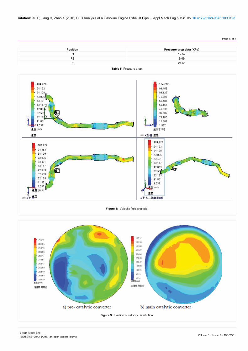
Velocity field analysis
The Figure 8 shows that when the inlet flow is 0.13 kg/s, the highest flow rate can reach 104.8 m/s, and the velocity muta-tion mainly occurred in the import (export) conical surface. Fluid through the catalytic converter, Reynolds number Re<2000, is laminar flow state.
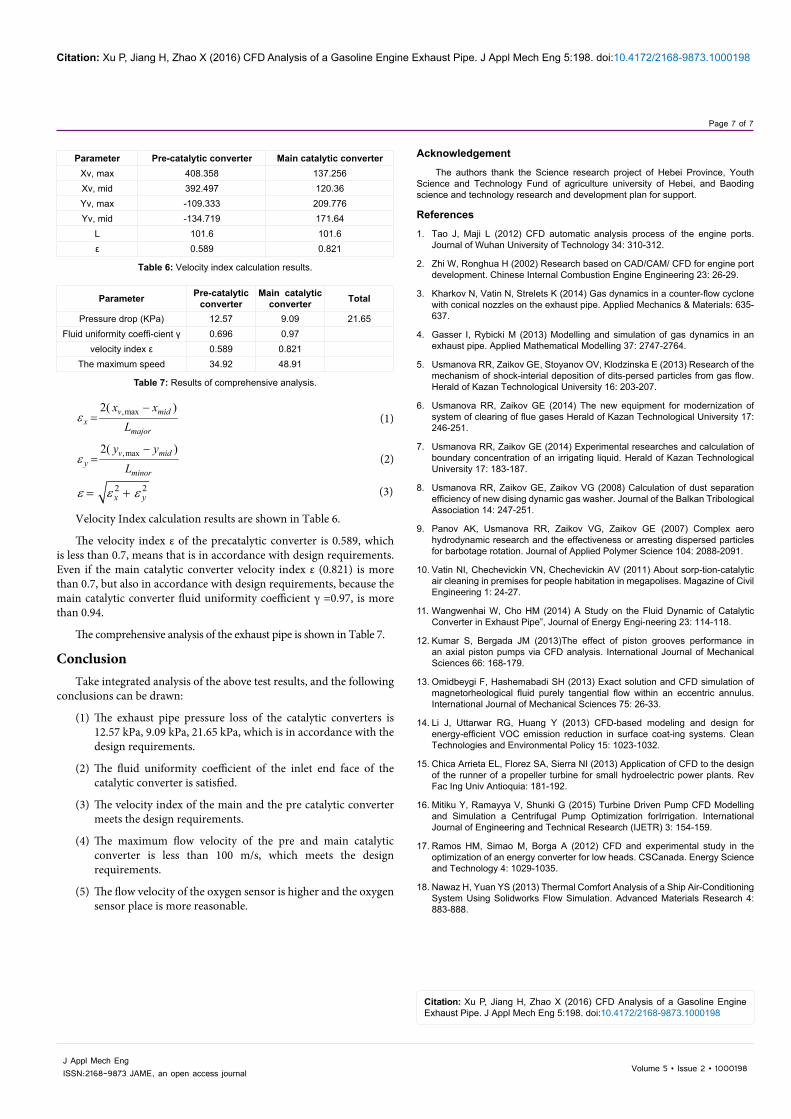
As is shown in Figure 9, the maximum speed of the pre-catalytic converter end face is 34.92 m/s, the maximum speed of the main catalytic converter end face is 48.91 m/s, which is less than 100 m/s, that is in accordance with the design requirements.
Oxygen sensor position CFD analysis .
The front oxygen sensor is located in the main flow area, which is in accordance with the design requirements; The rear oxygen sensor is located in the main flow area, which is in accordance with the design requirements. The analysis result is shown as Figure 10.
Fluid uniformity analysis
In general, the calculation of the fluid uniformity coefficient γ is only for the end face of catalytic converter. When γ <0.9, it is necessary to optimize the import.
After calculation, the fluid uniformity coefficient γ of the main catalytic converter end face is 0.97, and the precatalytic converter is 0.696. The results are shown in Figure 11.
Velocity Index is a criterion for judging the radial force of the carrier component, as shown in Figure 12, the calculation method is shown in formula (1~3). Under normal circumstances, when the velocity index ε ≤0.7, that is in accordance with design requirements, but when the fluid uniformity γ ≥ 0.94, without considering the influence of Velocity Index [18].
Figure 6: Pressure field distribution.
Figure 7: Pressure drop detection position.
Page 5 of 7
Citation: Xu P, Jiang H, Zhao X (2016) CFD Analysis of a Gasoline Engine Exhaust Pipe. J Appl Mech Eng 5:198. doi:10.4172/2168-9873.1000198
Volume 5 • Issue 2 • 1000198J Appl Mech EngISSN:2168-9873 JAME, an open access journal
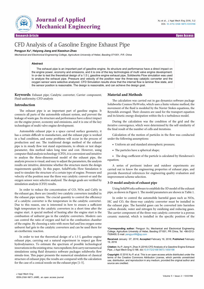
Position Pressure drop data (KPa)P1 12.57P2 9.09P3 21.65
Table 5: Pressure drop.
Figure 8: Velocity field analysis.
Figure 9: Section of velocity distribution.

Page 6 of 7
Citation: Xu P, Jiang H, Zhao X (2016) CFD Analysis of a Gasoline Engine Exhaust Pipe. J Appl Mech Eng 5:198. doi:10.4172/2168-9873.1000198
Volume 5 • Issue 2 • 1000198J Appl Mech EngISSN:2168-9873 JAME, an open access journal
Figure 10: Oxygen sensor position CFD analysis (pre & main).
Figure 11: Fluid uniformity analysis.
Figure 12: Velocity index.
Page 7 of 7
Citation: Xu P, Jiang H, Zhao X (2016) CFD Analysis of a Gasoline Engine Exhaust Pipe. J Appl Mech Eng 5:198. doi:10.4172/2168-9873.1000198
Volume 5 • Issue 2 • 1000198J Appl Mech EngISSN:2168-9873 JAME, an open access journal
,max2( )v midx
major
x xL
ε−
= (1)
,max2( )v midy
minor
y yL
ε−
= (2)
2 2x yε ε ε= + (3)
Velocity Index calculation results are shown in Table 6.
The velocity index ε of the precatalytic converter is 0.589, which is less than 0.7, means that is in accordance with design requirements. Even if the main catalytic converter velocity index ε (0.821) is more than 0.7, but also in accordance with design requirements, because the main catalytic converter fluid uniformity coefficient γ =0.97, is more than 0.94.
The comprehensive analysis of the exhaust pipe is shown in Table 7.
ConclusionTake integrated analysis of the above test results, and the following
conclusions can be drawn:
(1) The exhaust pipe pressure loss of the catalytic converters is 12.57 kPa, 9.09 kPa, 21.65 kPa, which is in accordance with the design requirements.
(2) The fluid uniformity coefficient of the inlet end face of the catalytic converter is satisfied.
(3) The velocity index of the main and the pre catalytic converter meets the design requirements.
(4) The maximum flow velocity of the pre and main catalytic converter is less than 100 m/s, which meets the design requirements.
(5) The flow velocity of the oxygen sensor is higher and the oxygen sensor place is more reasonable.
Parameter Pre-catalytic converter Main catalytic converterXv, max 408.358 137.256Xv, mid 392.497 120.36Yv, max -109.333 209.776Yv, mid -134.719 171.64
L 101.6 101.6ε 0.589 0.821
Table 6: Velocity index calculation results.
Parameter Pre-catalytic converter
Main catalytic converter Total
Pressure drop (KPa) 12.57 9.09 21.65Fluid uniformity coeffi-cient γ 0.696 0.97
velocity index ε 0.589 0.821The maximum speed 34.92 48.91
Table 7: Results of comprehensive analysis.
Acknowledgement
The authors thank the Science research project of Hebei Province, Youth Science and Technology Fund of agriculture university of Hebei, and Baoding science and technology research and development plan for support.
References
1. Tao J, Maji L (2012) CFD automatic analysis process of the engine ports. Journal of Wuhan University of Technology 34: 310-312.
2. Zhi W, Ronghua H (2002) Research based on CAD/CAM/ CFD for engine port development. Chinese Internal Combustion Engine Engineering 23: 26-29.
3. Kharkov N, Vatin N, Strelets K (2014) Gas dynamics in a counter-flow cyclone with conical nozzles on the exhaust pipe. Applied Mechanics & Materials: 635-637.
4. Gasser I, Rybicki M (2013) Modelling and simulation of gas dynamics in an exhaust pipe. Applied Mathematical Modelling 37: 2747-2764.
5. Usmanova RR, Zaikov GE, Stoyanov OV, Klodzinska E (2013) Research of the mechanism of shock-interial deposition of dits-persed particles from gas flow. Herald of Kazan Technological University 16: 203-207.
6. Usmanova RR, Zaikov GE (2014) The new equipment for modernization of system of clearing of flue gases Herald of Kazan Technological University 17: 246-251.
7. Usmanova RR, Zaikov GE (2014) Experimental researches and calculation of boundary concentration of an irrigating liquid. Herald of Kazan Technological University 17: 183-187.
8. Usmanova RR, Zaikov GE, Zaikov VG (2008) Calculation of dust separation efficiency of new dising dynamic gas washer. Journal of the Balkan Tribological Association 14: 247-251.
9. Panov AK, Usmanova RR, Zaikov VG, Zaikov GE (2007) Complex aero hydrodynamic research and the effectiveness or arresting dispersed particles for barbotage rotation. Journal of Applied Polymer Science 104: 2088-2091.
10. Vatin NI, Chechevickin VN, Chechevickin AV (2011) About sorp-tion-catalytic air cleaning in premises for people habitation in megapolises. Magazine of Civil Engineering 1: 24-27.
11. Wangwenhai W, Cho HM (2014) A Study on the Fluid Dynamic of Catalytic Converter in Exhaust Pipe”, Journal of Energy Engi-neering 23: 114-118.
12. Kumar S, Bergada JM (2013)The effect of piston grooves performance in an axial piston pumps via CFD analysis. International Journal of Mechanical Sciences 66: 168-179.
13. Omidbeygi F, Hashemabadi SH (2013) Exact solution and CFD simulation of magnetorheological fluid purely tangential flow within an eccentric annulus. International Journal of Mechanical Sciences 75: 26-33.
14. Li J, Uttarwar RG, Huang Y (2013) CFD-based modeling and design for energy-efficient VOC emission reduction in surface coat-ing systems. Clean Technologies and Environmental Policy 15: 1023-1032.
15. Chica Arrieta EL, Florez SA, Sierra NI (2013) Application of CFD to the design of the runner of a propeller turbine for small hydroelectric power plants. Rev Fac Ing Univ Antioquia: 181-192.
16. Mitiku Y, Ramayya V, Shunki G (2015) Turbine Driven Pump CFD Modelling and Simulation a Centrifugal Pump Optimization forIrrigation. International Journal of Engineering and Technical Research (IJETR) 3: 154-159.
17. Ramos HM, Simao M, Borga A (2012) CFD and experimental study in the optimization of an energy converter for low heads. CSCanada. Energy Science and Technology 4: 1029-1035.
18. Nawaz H, Yuan YS (2013) Thermal Comfort Analysis of a Ship Air-Conditioning System Using Solidworks Flow Simulation. Advanced Materials Research 4: 883-888.
Citation: Xu P, Jiang H, Zhao X (2016) CFD Analysis of a Gasoline Engine Exhaust Pipe. J Appl Mech Eng 5:198. doi:10.4172/2168-9873.1000198