CERTIFICATION REPORT Certification of Charpy V...
30
EUR 21766 EN - 2007 CERTIFICATION REPORT Certification of Charpy V-notch reference test pieces of 30 J nominal absorbed energy Certified Reference Material ERM ® -FA013at
Transcript of CERTIFICATION REPORT Certification of Charpy V...
EU
R21766
EN
-2007
CERTIFICATION REPORT
Certification of Charpy V-notch reference test pieces of 30 J nominal absorbed energy
Certified Reference Material ERM®-FA013at

The mission of IRMM is to promote a common and reliable European measurement system in support of EU policies. European Commission Joint Research Centre Institute for Reference Materials and Measurements Contact information CRM Sales European Commission Joint Research Centre Institute for Reference Materials and Measurements Retieseweg 111 B-2440 Geel • Belgium Email: [email protected] Tel.: +32 (0)14 571 705 Fax: +32 (0)14 590 406 http://www.erm-crm.org Legal Notice Neither the European Commission nor any person acting on behalf of the Commission is responsible for the use which might be made of this publication. EUR 21766 EN ISBN 92-894-9921-4 ISSN 1018-5593 Luxembourg: Office for Official Publications of the European Communities © European Communities, 2007 Reproduction is authorised provided the source is acknowledged Printed in Belgium
CERTIFICATION REPORT
Certification of Charpy V-notch reference test pieces of 30 J nominal absorbed energy
Certified Reference Material ERM®-FA013at
G. Roebben, A. Lamberty
European Commission, Joint Research Centre Institute for Reference Materials and Measurements
Geel, Belgium

1
Abstract This certification report describes the processing and characterisation of ERM®-FA013at, a batch of Charpy V-notch certified reference test pieces. Sets of five of these test pieces are used for the verification of pendulum impact test machines according to EN 10045-2 (Charpy impact test on metallic materials, Part 2. Method for the verification of impact testing machines [1]) or according to ISO 148-2 (Metallic materials - Charpy pendulum impact test – Part 2: Verification of test machines [2]). The certified value for KV (= energy required to break a V-notched test piece using a pendulum impact test machine) is 32.4 J. The associated uncertainty (1.1 J, k = 2 corresponding to a confidence level of 95 %) is calculated for the mean of a set of five test pieces. The certified value is traceable to the Charpy impact test method as described in EN 10045-1 [3] and ISO 148 [4], via the corresponding Master Batch ERM®-FA013d of the same nominal absorbed energy (30 J).

2
3
Table of Contents
Abstract ..........................................................................................................1
Table of Contents...........................................................................................3
List of abbreviations and symbols ...............................................................5
1. Introduction: the Charpy pendulum impact test ..................................7
2. The certification concept of Master Batch and Secondary Batch ......8
2.1. Difference between Master and Secondary Batches ...................................8 2.2. Certification of a Secondary Batch of Charpy V-notch test pieces ...............8
3. Participants ...........................................................................................10
4. Processing ............................................................................................11
4.1. Processing of hot-rolled bars......................................................................11 4.2. Heat-treatment of hot-rolled bars ...............................................................11 4.3. Machining of Charpy test pieces ................................................................11 4.4. Quality control ............................................................................................12 4.5. Packaging and storage...............................................................................12
5. Characterisation ...................................................................................13
5.1. Characterisation tests.................................................................................13 5.2. Data from Master Batch ERM®-FA013d .....................................................14 5.3. Calculation of KVCRM and of uchar ................................................................14
6. Homogeneity .........................................................................................15
7. Stability..................................................................................................16
8. Evaluation of results ............................................................................17
8.1. Calculation of certified value, combined and expanded uncertainty...........17 8.2. Traceability .................................................................................................17 8.3. Commutability.............................................................................................17 8.4. Summary of results ....................................................................................18
9. Instructions for use ..............................................................................19

4
9.1. Intended use...............................................................................................19 9.2. Sample preparation ....................................................................................19 9.3. Pendulum impact tests ...............................................................................19
10. Acknowledgements ..........................................................................20
11. References.........................................................................................21
Annex 1.........................................................................................................22
Annex 2.........................................................................................................23
5
List of abbreviations and symbols AISI American Iron and Steel Institute
ASTM American Society for Testing and Materials
BCR Community Bureau of Reference
CEN European Committee for Standardization
CRM Certified Reference Material
EC European Commission
EN European Norm
ERM® European Reference Material
h hour
IMB International Master Batch
IRMM Institute for Reference Materials and Measurements, Joint Research Centre, European Commission
ISO International Organisation for Standardisation
JRC Joint Research Centre
k Coverage factor
KV Absorbed energy = energy required to break a V-notched test piece of defined shape and dimensions when tested with a pendulum impact testing machine
KVCRM Certified KV value of a set of 5 reference test pieces from the Secondary Batch
KVMB Certified KV value of the Master Batch test pieces
LNE Laboratoire National d’Essais
MB Master Batch
min minute

6
nMB Number of samples of the Master Batch tested during certification of the Secondary Batch
nSB Number of samples of the Secondary Batch tested for certification
RSD Relative standard deviation
SB Secondary Batch
sMB Standard deviation of the nMB results of the samples of the Master Batch tested for the certification of the Secondary Batch
sSB Standard deviation of the nSB results of the samples of the Secondary Batch tested for its characterisation
uCRM Combined standard uncertainty of KVCRM
UCRM Expanded uncertainty (k = 2, confidence level 95 %) of KVCRM
uchar Standard uncertainty of the result of the characterisation tests
uh Homogeneity contribution to uncertainty
uMB Standard uncertainty of KVMB
MBX Mean KV value of the nMB measurements on samples of the Master Batch tested when characterising the Secondary Batch
SBX Mean KV value of the nSB results of the samples of the Secondary Batch tested for its characterisation
Δh difference between the height of the centre of gravity of the pendulum prior to release and at end of first half-swing, after breaking the test sample
νeff Effective number of degrees of freedom associated with the uncertainty of the certified value
7
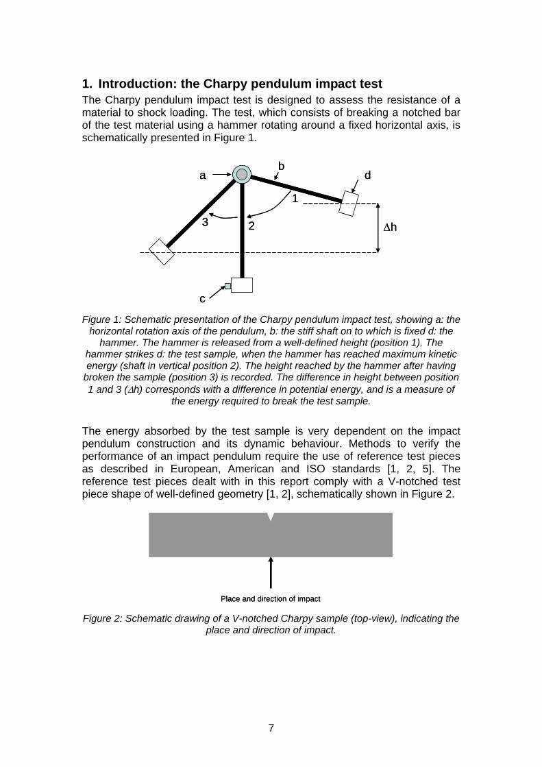
1. Introduction: the Charpy pendulum impact test The Charpy pendulum impact test is designed to assess the resistance of a material to shock loading. The test, which consists of breaking a notched bar of the test material using a hammer rotating around a fixed horizontal axis, is schematically presented in Figure 1.
1
23 Δh
ab
c
d
1
23 Δh
ab
c
d
Figure 1: Schematic presentation of the Charpy pendulum impact test, showing a: the
horizontal rotation axis of the pendulum, b: the stiff shaft on to which is fixed d: the hammer. The hammer is released from a well-defined height (position 1). The
hammer strikes d: the test sample, when the hammer has reached maximum kinetic energy (shaft in vertical position 2). The height reached by the hammer after having
broken the sample (position 3) is recorded. The difference in height between position 1 and 3 (Δh) corresponds with a difference in potential energy, and is a measure of
the energy required to break the test sample.
The energy absorbed by the test sample is very dependent on the impact pendulum construction and its dynamic behaviour. Methods to verify the performance of an impact pendulum require the use of reference test pieces as described in European, American and ISO standards [1, 2, 5]. The reference test pieces dealt with in this report comply with a V-notched test piece shape of well-defined geometry [1, 2], schematically shown in Figure 2.
Place and direction of impactPlace and direction of impact Figure 2: Schematic drawing of a V-notched Charpy sample (top-view), indicating the
place and direction of impact.

8
2. The certification concept of Master Batch and Secondary Batch
2.1. Difference between Master and Secondary Batches The BCR reports by Marchandise et al. [6] and Varma [7] provide details of the certification of the BCR “Master Batches” (MB) of Charpy V-notch certified reference test pieces. The certified value of a Master Batch is obtained using an international laboratory intercomparison. This report describes the production of a “Secondary Batch” (SB) of Charpy V-notch certified reference test pieces at the Institute for Reference Materials and Measurements (IRMM) of the European Commission (EC) Joint Research Centre (JRC). The work was performed in accordance with procedures described in the BCR reports [6] Varma [7]. The certification of a SB is based on the comparison of a set of SB test pieces with a set of test pieces from the corresponding MB under repeatability conditions on a single pendulum. While the MB-SB approach necessarily results in a larger uncertainty of the certified value of SB in comparison with the MB, the uncertainty can be kept sufficiently small to meet the requirements of the intended use of the certified reference material (CRM). Avoiding the need for an international interlaboratory comparison for each produced batch, the MB-SB approach allows cost-efficient production of certified reference test pieces. The BCR reports [6] and [7] were published in 1991 and 1999, respectively. Since 2000, the calculation of the certified value and the estimation of its uncertainty have been updated to an approach compliant with the ISO Guide to the Expression of Uncertainty in Measurement [8]. This revised approach was developed and presented by Ingelbrecht et al. [9, 10], and is summarised below.
2.2. Certification of a Secondary Batch of Charpy V-notch test pieces The certified absorbed energy of a SB of Charpy V-notch reference test pieces (KVCRM) is calculated from the mean KV-value of a set of SB-samples ( SBX ) tested on a single pendulum. This value SBX has to be corrected for the bias of this particular pendulum. The bias of the pendulum at the moment of testing the samples of the SB, is estimated by comparing the mean KV-value of a number of samples of the MB ( MBX ), tested together with the SB samples under repeatability conditions, with the certified value of the MB (KVMB). KVCRM is then calculated as follows [10]:
⎥⎦
⎤⎢⎣
⎡⋅= SB
MB
MBCRM X
XKVKV Eq. 1
For this approach to be reliable, the pendulum used for the tests on MB and SB in repeatability conditions, must be well performing. In other words, the

9
ratio MB
MB
XKV must be close to 1. IRMM now allows a difference of 5 %
(KVMB > 40 J) or 2 J (KVMB < 40 J) between KVMB and MBX , corresponding with the level of bias allowed for reference pendulums specified in EN 10045-2 [1] and ISO 148-3 [11]. Also, for reasons of commutability, a comparable response of the pendulum to the MB and SB samples is required. This is the reason why MB and SB samples are made from nominally the same steel. Moreover, it is checked that
the ratio MB
CRM
KVKV is close to 1. IRMM now allows a difference of 20 %
(KVMB > 40 J) or 8 J (KVMB < 40 J) between KVCRM and KVMB.

10
3. Participants The processing of the SB test pieces was carried out by the Laboratoire National d’Essais (LNE), Trappes (FR), using steel bars produced at Cogne Acciai Speciali, Aosta (IT). The MB samples used in the characterisation of the SB were provided by IRMM, Geel (BE). Characterisation of the SB was carried out at IRMM using a pendulum verified according to the criteria imposed by EN 10045-2 [1] and ISO 148-2 [2]. Data evaluation was performed at IRMM.

11
4. Processing The ERM®-FA013at test pieces were prepared from AISI 4340 steel. The steel was cast and rolled into bars at Cogne Acciai Speciali (see section 4.1). Production of the test pieces from these bars was performed under the supervision of LNE (see sections 4.2, 4.3, 4.4, and 4.5).
4.1. Processing of hot-rolled bars The base material consisted of AISI 4340 steel, produced at Cogne Acciai Speciali. To limit the amount of impurities potentially affecting the homogeneity of the fracture resistance, the following compositional tolerances were imposed on the selected steel batch: Mn 0.7 – 0.8, Mo 0.23 - 0.28, Ni 1.7 – 1.85, P < 0.01, Si 0.2 – 0.35, S < 0.008 (in wt %), which is stricter than generally allowed for AISI 4340. The ingot was hot rolled, resulting in bars that were 4 m long and with a squared cross-section of 11.5 mm. For the ERM®-FA013at batch, steel was used from ingot number 960133, billet E. A billet is a semi-finished hot-rolled product, in this case of cross-section 108.5 mm, which is between the ingot (560 mm cross-section) stage and the final required bars (11.5 mm cross-section). A full description of the processing and quality check of the steel bars is available in [12].
4.2. Heat-treatment of hot-rolled bars The heat treatment of the hot-rolled bars was performed at Aubert&Duval, Gennevilliers (FR). 20 bars were heat-treated together. Bars were placed onto rollers which slowly move the bars back and forth inside the furnace during the heat treatment to increase the homogeneity of the resulting microstructure. The first heat treatment was an austenisation treatment performed in a furnace of « class 10 °C »1 at 850 °C for 31 minutes. From this furnace, the bars were quenched into oil at 40 °C. After the oil-quench, the samples were annealed in a second furnace (class 5 °C) at 410 °C for 121 minutes. After this annealing treatment, the samples were cooled down in air. After heat treatment, a limited number of samples (6) were machined for a preliminary check of the obtained energy level. Results indicated an average KV-level (28.3 J) close to the desired nominal energy level (30 J).
4.3. Machining of Charpy test pieces After the heat treatment the samples were machined to dimensional tolerances imposed in EN 10045-2 [1]. The batch code was engraved on one end face of each sample (‘30’ indicates the nominal absorbed energy level (30 J); ‘AT’ is the letter code as assigned consecutively to batches of the same nominal absorbed energy). The V-notch was introduced using an electro-erosion tool.
1 In a furnace of class x °C, the variation of the temperature is smaller than x °C. The furnaces used have 10 heating zones. Each zone has 3 controlling thermocouples and 3 measurement thermocouples. These are regularly calibrated. When one faulty thermocouple is detected, it is replaced by a thermocouple produced with wire from the same roll. When a roll is exhausted, all thermocouples are replaced with new ones.

12
4.4. Quality control When all samples from the batch were fully machined, a selection of 25 samples was made. The dimensions of the 25 samples were checked on April 3, 2002 against the criteria specified in EN 10045-2 [1] (length
0.025.00.55 mm, height 06.000.10 ± mm, width 075.000.10 ± mm, notch angle
145 ± °, height remaining at notch root 06.000.8 ± mm, radius at notch root 025.025.0 ± mm, distance between the plane of symmetry of the notch and
the longitudinal axis of the test piece 10.050.27 ± mm). None of the samples were outside the ranges specified in EN 10045-2 [1]. The 25 samples checked for geometrical compliance were impact tested on April 3, 2002 on the Tinius Olsen 358 Joules pendulum - which is one of the French reference pendulums - at LNE. The results are reported in certificate LNE n° B100806/CQPE/2 [13]. The average KV of the 25 samples was 32.6 J, sufficiently close to the target value (30 J). The standard deviation of the test results (s = 0.54 J, RSD = 1.7 %) was smaller than the maximum allowed 3 %. The variation was checked again during the certification tests at IRMM (see section 5).
4.5. Packaging and storage Finally, the samples were cleaned and packed in sets of 5, in oil-filled and closed plastic bags. These oil-filled bags, together with a label, again were packed in a sealed plastic bag, and shipped to IRMM. After arrival (April 2002), the 1265 samples (or 253 sets) were registered and stored at room temperature, pending distribution.

13
5. Characterisation
5.1. Characterisation tests 30 samples from ERM®-FA013at (sets 3, 40, 97, 138, 212 and 252) were tested under repeatability conditions with 25 samples from MB ERM®-FA013d (sets 57, 78, 88, 98 and 107), using the Instron Wolpert PW 30 (serial number 7300 H1527) machine of IRMM, an impact pendulum yearly verified according to procedures described in EN 10045-2 [1] and ISO 148-2 [2]. Tests were performed on November 6, 2007 (laboratory temperature 20 ± 1 °C), in accordance with EN 10045-1 and ISO 148. The measured absorbed energy values were corrected for friction and windage losses. Data obtained on individual test pieces are shown in Figure 3 and in Annex 1. The results of the measurements are summarised in Table 1.
20.00
25.00
30.00
35.00
40.00
0 10 20 30 40 50Test sequence
Abs
orbe
d en
ergy
(J)
SB MB
Figure 3: Absorbed energy values of the 30 test pieces of ERM®-FA013at and 25 test
pieces of ERM®-FA013d displayed in the actual test sequence.
Table 1: Characterisation measurements of Batch ERM®-FA013at.
Number of test pieces
Mean value Standard deviation
Relative standard deviation
nMB or nSB MBX or SBX (J) sMB or sSB (J) RSD (%)
ERM®-FA013d (MB)
25 25.78 1.10 4.3
ERM®-FA013at (SB)
30 33.17 0.73 2.2
The RSD of the 30 SB-results (2.2 %) meets the EN 10045-2 and ISO 148-3 acceptance criteria for a batch of reference materials (RSD < 5 %), as well as the more stringent acceptance criterion (RSD < 3 %) contractually fixed between IRMM and its sample supplier.

14
5.2. Data from Master Batch ERM®-FA013d To calculate KVCRM for ERM®-FA013at one needs KVMB of the MB used, i.e. ERM®-FA013d. Table 2 shows the main MB-data, taken from the Certificate of Analysis of ERM®-FA013d (Annex 2), which is the revised, ERM-version of the originally issued certificate, based on the certification report of the MB [6].
Table 2: Data from the certification of Master Batch ERM®-FA013d [6].
Certified absorbed energy of Master
Batch
KVMB (J)
Standard uncertainty of
KVMB
uMB (J)
Standard uncertainty of
KVMB
uMB (%)
ERM®-FA013d 25.2 0.2 0.8
5.3. Calculation of KVCRM and of uchar From the data in Table 1 and Table 2, and using Eq. 1, one readily obtains that KVCRM = 32.4 J. The uncertainty associated with the characterisation of the SB, uchar, is assessed as in Eq. 2 [10], which sums the relative uncertainties of the three factors in Eq. 1:
2MBMB
2MB
2SBSB
2SB
2MB
2MB
CRMchar Xns
Xns
KVuKVu
⋅+
⋅+= Eq. 2
SBX and MBX were obtained under repeatability conditions. Therefore, the
uncertainty of the ratio MBSB X/X is not affected by the contributions from reproducibility and bias of the pendulum used to compare MB and SB. Table 3 summarises the input quantities of the uchar uncertainty budget, their respective statistical properties, and shows how they were combined. The effective number of degrees of freedom for uchar is obtained using the Welch-Satterthwaite equation [8].
Table 3: Uncertainty budget for uchar
symbol source of uncertainty
measured value
(J)
standard uncertainty
(J)
probability distribution
divisor sensitivity coefficient
relative uncertainty
(%)
degrees of
freedom
KVMB certification of MB
25.2 0.2 normal 1 1 0.79 6
SBX 33.17 0.13 normal 1 1 0.40 29
MBX
comparison of SB and MB in repeatability conditions 25.78 0.22 normal 1 1 0.86 24
uchar (%) 1.23
uchar (J) 0.40
25

15
6. Homogeneity The test pieces constituting a CRM unit are sampled from the SB, which is sufficiently, but not perfectly, homogeneous. Therefore, a separate homogeneity contribution uh to the uncertainty of the certified value is required. Here, uh is estimated from sSB, the standard deviation of the results of the characterisation tests on the SB (see Table 1). The samples tested were randomly selected from the whole batch. The number of samples tested (30) is largely sufficient to reflect the homogeneity of the full SB (1265 samples). The effect of sSB on the uncertainty of the certified value depends on the number of samples over which the KV-value is averaged. EN 10045-2 [1] and in ISO 148-2 [2] specify that the pendulum verification must be performed using 5 test pieces. Therefore, a CRM-unit consists of 5 test pieces, and
J33.05
su SBh == . uh is probably a slight overestimation, since it contains also
the repeatability of the instrument. However, the latter cannot be separated or separately measured.

16
7. Stability The stability of the absorbed energy of Charpy V-notch certified reference test pieces was first systematically investigated for samples of nominally 120 J by Pauwels et al., who did not observe measurable changes of absorbed energy [14]. New evidence for the stability of the reference test pieces produced from AISI 4340 steel of lower energy levels (nominally 15 J, 30 J and 100 J) has been obtained recently, during the International Master Batch (IMB) project [15]. In the IMB-project, the stability of the certified test pieces is deduced from the unchanged value of the mean of means of the absorbed energy obtained on 7 reference pendulums over a three year period. Given the large sample-to-sample heterogeneity, the ageing effects are undetectable when testing limited numbers of samples, and the uncertainty contribution from instability is considered to be insignificant. The main reason for the microstructural stability of the certified reference test pieces is the annealing treatment to which the samples were subjected after the austenisation treatment. Annealing is performed at temperatures where the equilibrium phases are the same as the (meta-)stable phases at ambient temperature (α-Fe and Fe3C). The only driving force for instability stems from the difference in solubility of interstitial elements in the α-Fe matrix, between annealing and ambient temperature. Relaxation of residual (micro-)stress by short-range diffusion or the additional formation or growth of precipitates during the shelf-life of the certified reference test pieces is expected to proceed but slowly. Rather than neglecting the stability issue, efforts are spent to better establish the stability of the certified values of batches of Charpy CRMs. Until such further notice, it is decided to specify a limited shelf-life. A period of 10 years is chosen, counting from the date of the characterisation tests on the SB. Since batch ERM®-FA013at was characterised in November, 2007, the validity of the certificate stretches until November, 2017.

17
8. Evaluation of results
8.1. Calculation of certified value, combined and expanded uncertainty As shown in 5.2, KVCRM = 32.4 J. The uncertainty of the certified value is obtained by combining the contributions from the characterisation study, uchar, and from the homogeneity assessment, uh, as is summarized in the following uncertainty budget (Table 4).
Table 4: Uncertainty budget of KVCRM
symbol source of uncertainty absolute value (J) ui (J) degrees of
freedom
uchar characterisation of SB 0.40 0.40 25
uh homogeneity of SB 0.33 0.33 29
Combined standard uncertainty, uCRM 0.52 J 50
Expanded Uncertainty, k = 2, UCRM 1.1 J νeff
The relevant number of degrees of freedom calculated using the Welch-Satterthwaite equation [8], is sufficiently large (νeff = 50) to justify the use of a coverage factor k = 2 to expand the confidence level to about 95 %. The obtained expanded uncertainty provides justification for the SB-MB approach followed: UCRM is sufficiently smaller than the verification criterion of 4 J or even 2 J (for reference pendulums).
8.2. Traceability The absorbed energy KV is a method-specific value, and can only be obtained by following the procedures specified in EN 10045-1 [3] and ISO 148 [4]. The certified value of the MB ERM®-FA013d is traceable to these standard procedures as it was obtained using an interlaboratory comparison, involving a representative selection of qualified laboratories performing the tests in accordance with the standard procedures. The certified value of ERM®-FA013at, is made traceable to the certified value of the MB using tests on SB and MB samples in repeatability conditions. Therefore the certified value of ERM®-FA013at is traceable to the Charpy impact test as described in EN 10045-1 and ISO 148.
8.3. Commutability The intended use of the certified reference test pieces is the verification of Charpy impact pendulums. During the certification of the MB, 7 different pendulums were used, each equipped with a ISO-type striker of 2 mm tip radius. Until further notice, the certified values are not to be used when the test pieces are broken with an ASTM-type striker of 8 mm tip radius, although the expected differences can be small for materials with relatively low absorbed energy such as the ERM®-FA013 batches of 30 J nominal absorbed energy [14].

18
8.4. Summary of results The certified value and associated uncertainties are summarized in Table 5.
Table 5: Certified value and associated uncertainties for ERM®-FA013at.
Certified mean value for set of 5 test
pieces
KVCRM (J)
Combined standard
uncertainty
uCRM (J)
Expanded uncertainty
(k = 2)
UCRM (J)
ERM®-FA013at 32.4 0.52 1.1

19
9. Instructions for use
9.1. Intended use Samples of ERM®-FA013at correspond with the ‘(certified) BCR test pieces’ as referred to in EN 10045-2 [1], as well as with the ‘certified reference test pieces’ as defined in ISO 148-3 [11]. Sets of five of these certified reference test pieces are intended for the indirect verification of impact testing machines with a striker of 2 mm tip radius according to procedures described in detail in EN 10045-2 [1] and ISO 148-2 [2].
9.2. Sample preparation Special attention is drawn to cleaning of the specimens prior to the tests. It is mandatory to remove the oil from the sample surface prior to testing, without damaging the edges of the sample. Between the moment of removing the protective oil layer and the actual test, corrosion can occur. This must be avoided by limiting this period of time, while keeping the sample clean. The following procedure is considered good practice. 1. First use absorbent cleaning-tissue to remove the excess oil. Pay
particular attention to the notch of the sample, but do not use hard (e.g. steel) brushes to remove the oil from the notch.
2. Submerge the samples in ethanol for about 5 min. Use of ultrasonication is encouraged, but only if the edges of the samples are prevented from rubbing against each other. To reduce the consumption of solvent, it is allowed to make a first cleaning step with detergent, immediately prior to the solvent step.
3. Once samples are removed from the solvent, only manipulate the samples wearing clean gloves. This is to prevent development of corrosion between the time of cleaning and the actual test.
4. Before testing, bring the specimens to the test temperature (20 ± 2 °C). To assure thermal equilibrium is reached, move the specimens to the test laboratory at least 3 h before the tests.
9.3. Pendulum impact tests After cleaning, the 5 samples constituting a CRM-unit need to be broken with a pendulum impact test machine in accordance with EN 10045-2 [1] or ISO 148-2 [2] standards. Prior to the tests, the anvils must be cleaned. It must be noted that Charpy test pieces sometimes leave debris on the Charpy pendulum anvils. Therefore, the anvils must be checked regularly and if debris is found, it must be removed. The uncertainty of the certified value applies to the mean of the 5 KV-values.

20
10. Acknowledgements The authors wish to thank Mrs. A. Munoz-Pineiro (IRMM), Mr. W. Philipp (IRMM), Mr. T. Linsinger (IRMM) and Mr. H. Emons (IRMM) and the experts of the Certification Advisory Panel “Physical and physicochemical properties’, Mr. J. De Kinder, Mr. J. Dusza and Mr. N. Jennett, for reviewing of the certification report.
21
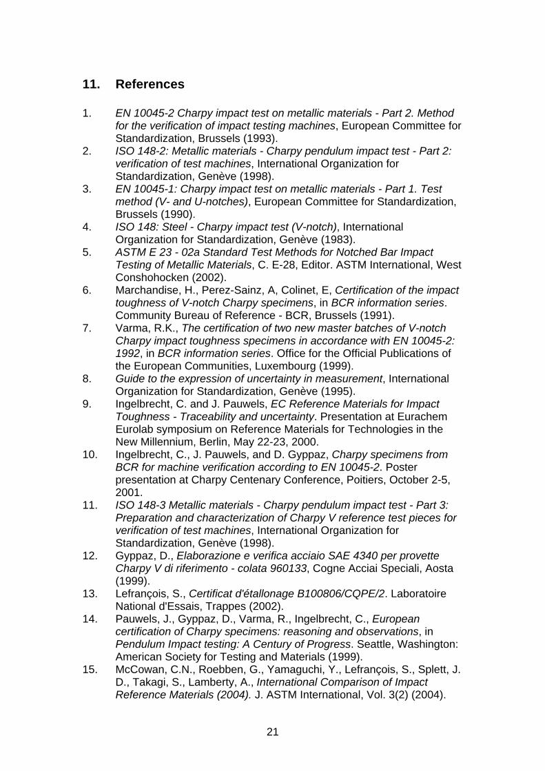
11. References 1. EN 10045-2 Charpy impact test on metallic materials - Part 2. Method
for the verification of impact testing machines, European Committee for Standardization, Brussels (1993).
2. ISO 148-2: Metallic materials - Charpy pendulum impact test - Part 2: verification of test machines, International Organization for Standardization, Genève (1998).
3. EN 10045-1: Charpy impact test on metallic materials - Part 1. Test method (V- and U-notches), European Committee for Standardization, Brussels (1990).
4. ISO 148: Steel - Charpy impact test (V-notch), International Organization for Standardization, Genève (1983).
5. ASTM E 23 - 02a Standard Test Methods for Notched Bar Impact Testing of Metallic Materials, C. E-28, Editor. ASTM International, West Conshohocken (2002).
6. Marchandise, H., Perez-Sainz, A, Colinet, E, Certification of the impact toughness of V-notch Charpy specimens, in BCR information series. Community Bureau of Reference - BCR, Brussels (1991).
7. Varma, R.K., The certification of two new master batches of V-notch Charpy impact toughness specimens in accordance with EN 10045-2: 1992, in BCR information series. Office for the Official Publications of the European Communities, Luxembourg (1999).
8. Guide to the expression of uncertainty in measurement, International Organization for Standardization, Genève (1995).
9. Ingelbrecht, C. and J. Pauwels, EC Reference Materials for Impact Toughness - Traceability and uncertainty. Presentation at Eurachem Eurolab symposium on Reference Materials for Technologies in the New Millennium, Berlin, May 22-23, 2000.
10. Ingelbrecht, C., J. Pauwels, and D. Gyppaz, Charpy specimens from BCR for machine verification according to EN 10045-2. Poster presentation at Charpy Centenary Conference, Poitiers, October 2-5, 2001.
11. ISO 148-3 Metallic materials - Charpy pendulum impact test - Part 3: Preparation and characterization of Charpy V reference test pieces for verification of test machines, International Organization for Standardization, Genève (1998).
12. Gyppaz, D., Elaborazione e verifica acciaio SAE 4340 per provette Charpy V di riferimento - colata 960133, Cogne Acciai Speciali, Aosta (1999).
13. Lefrançois, S., Certificat d'étallonage B100806/CQPE/2. Laboratoire National d'Essais, Trappes (2002).
14. Pauwels, J., Gyppaz, D., Varma, R., Ingelbrecht, C., European certification of Charpy specimens: reasoning and observations, in Pendulum Impact testing: A Century of Progress. Seattle, Washington: American Society for Testing and Materials (1999).
15. McCowan, C.N., Roebben, G., Yamaguchi, Y., Lefrançois, S., Splett, J. D., Takagi, S., Lamberty, A., International Comparison of Impact Reference Materials (2004). J. ASTM International, Vol. 3(2) (2004).
22
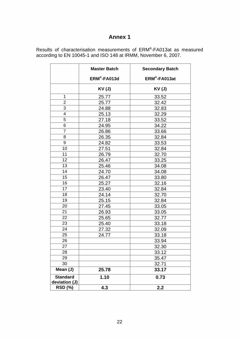
Annex 1 Results of characterisation measurements of ERM®-FA013at as measured according to EN 10045-1 and ISO 148 at IRMM, November 6, 2007.
Master Batch
ERM®-FA013d
Secondary Batch
ERM®-FA013at
KV (J) KV (J)
1 25.77 33.52 2 25.77 32.42 3 24.88 32.83 4 25.13 32.29 5 27.18 33.52 6 24.95 34.22 7 26.86 33.66 8 26.35 32.84 9 24.82 33.53
10 27.51 32.84 11 26.79 32.70 12 26.47 33.25 13 25.46 34.08 14 24.70 34.08 15 26.47 33.80 16 25.27 32.16 17 23.40 32.84 18 24.14 32.70 19 25.15 32.84 20 27.45 33.05 21 26.93 33.05 22 25.65 32.77 23 25.40 33.18 24 27.32 32.09 25 24.77 33.18 26 33.94 27 32.30 28 33.12 29 35.47 30 32.71
Mean (J) 25.78 33.17 Standard
deviation (J) 1.10 0.73
RSD (%) 4.3 2.2

23
Annex 2

24

25

European Commission EUR 21766 EN – Joint Research Centre – Institute for Reference Materials and Measurements Title: Certification of Charpy V-notch reference test pieces of 30 J nominal absorbed energy, ERM®-FA013at Author(s): G. Roebben, A. Lamberty Luxembourg: Office for Official Publications of the European Communities 2007 – 24 pp. – 21.0 x 29.7 cm EUR - Scientific and Technical Research series – ISSN 1018-5593 ISBN 92-894-9921-4 Abstract This certification report describes the processing and characterisation of ERM®-FA013at, a batch of Charpy V-notch certified reference test pieces. Sets of five of these test pieces are used for the verification of pendulum impact test machines according to EN 10045-2 (Charpy impact test on metallic materials, Part 2. Method for the verification of impact testing machines [1]) or according to ISO 148-2 (Metallic materials - Charpy pendulum impact test – Part 2: Verification of test machines [2]). The certified value for KV (= energy required to break a V-notched test piece using a pendulum impact test machine) is 32.4 J. The associated uncertainty (1.1 J, k = 2 corresponding to a confidence level of 95 %) is calculated for the mean of a set of five test pieces. The certified value is traceable to the Charpy impact test method as described in EN 10045-1 [3] and ISO 148 [4], via the corresponding Master Batch ERM®-FA013d of the same nominal absorbed energy (30 J).

The mission of the JRC is to provide customer-driven scientific and technical support for the conception, development, implementation and monitoring of EU policies. As a service of the European Commission, the JRC functions as a reference centre of science and technology for the Union. Close to the policy-making process, it serves the common interest of the Member States, while being independent of special interests, whether private or national.
LA-N
A-21766-EN
-C