
CERN Cryogenics
174
Introduction to Cryogenic Engineering 5. - 9.12.2005 G. Perinić, G. Vandoni, T. Niinikoski, CERN
-
Upload
nicanor-mariotti -
Category
Documents
-
view
54 -
download
4
Transcript of CERN Cryogenics
Introduction to Cryogenic Engineering
5. - 9.12.2005
G. Perinić, G. Vandoni, T. Niinikoski, CERN
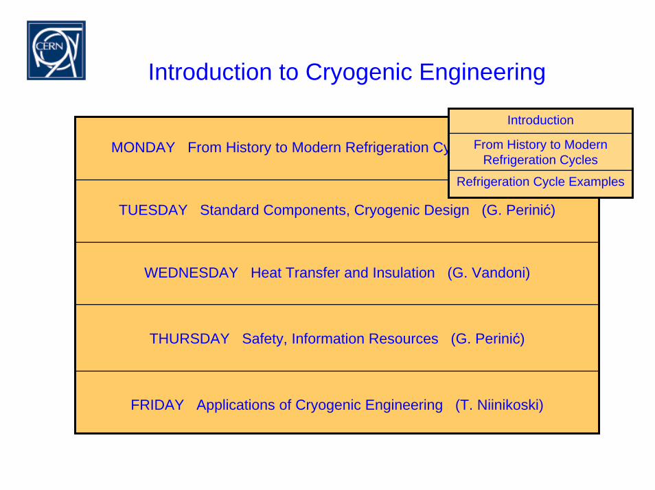
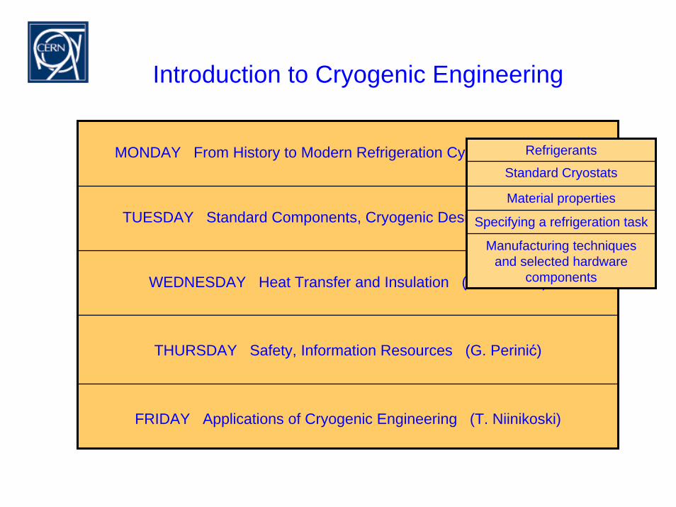
Introduction to Cryogenic Engineering
MONDAY From History to Modern Refrigeration Cycles (G. Perinić)
TUESDAY Standard Components, Cryogenic Design (G. Perinić)
WEDNESDAY Heat Transfer and Insulation (G. Vandoni)
THURSDAY Safety, Information Resources (G. Perinić)
FRIDAY Applications of Cryogenic Engineering (T. Niinikoski)
Introduction
From History to Modern Refrigeration Cycles
Refrigeration Cycle Examples

Day 1
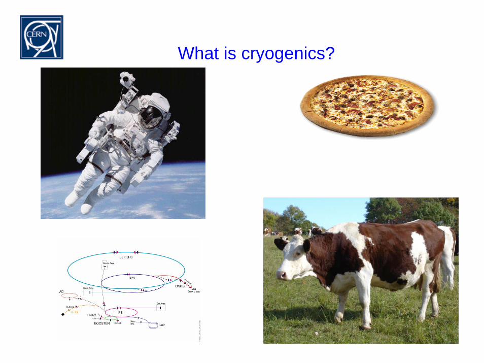
What is cryogenics?

History
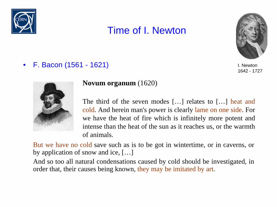
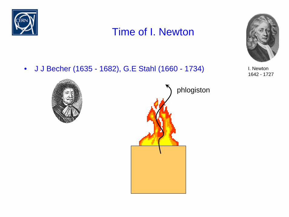
Time of I. Newton
• F. Bacon (1561 - 1621)
But we have no cold save such as is to be got in wintertime, or in caverns, or by application of snow and ice, […]And so too all natural condensations caused by cold should be investigated, in order that, their causes being known, they may be imitated by art.
I. Newton 1642 - 1727
Novum organum (1620)
The third of the seven modes […] relates to […] heat andcold. And herein man's power is clearly lame on one side. For we have the heat of fire which is infinitely more potent and intense than the heat of the sun as it reaches us, or the warmthof animals.
Time of I. Newton
• Known refrigeration methods
– refrigeration by a colder objecte.g. ice or snow
– refrigeration by evaporation
– refrigeration by dissolving saltpeter in water(saltpeter = sodium nitrate NaNO3 or potassium nitrate KNO3 )
I. Newton 1642 - 1727
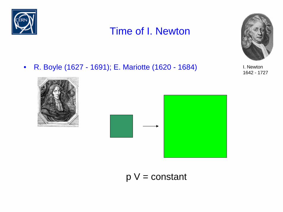
Time of I. Newton
• R. Boyle (1627 - 1691); E. Mariotte (1620 - 1684) I. Newton 1642 - 1727
p V = constant
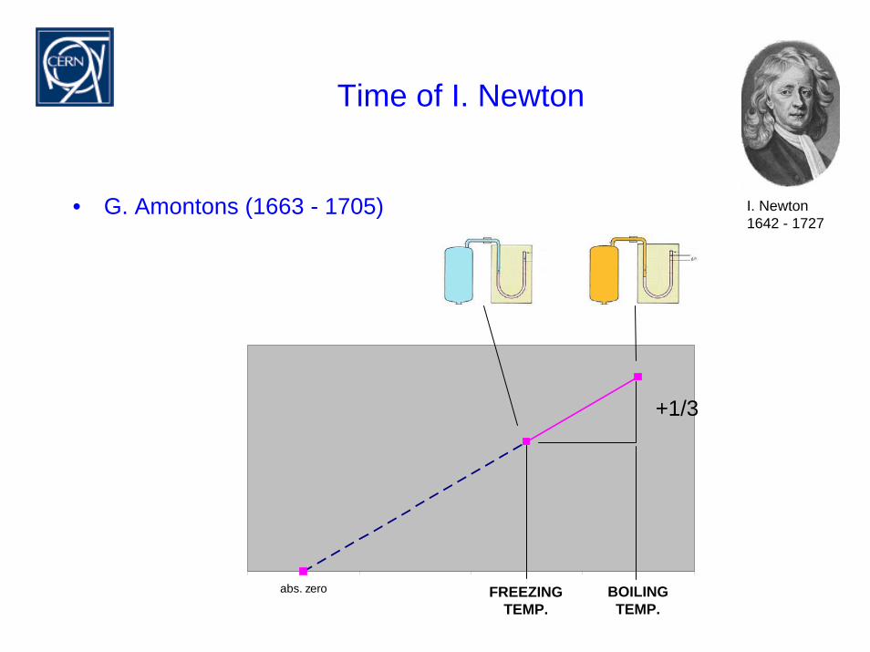
Time of I. Newton
• G. Amontons (1663 - 1705) I. Newton 1642 - 1727
abs. zero ice boil.
+1/3
FREEZINGTEMP.
BOILINGTEMP.
Further development of thermodynamics
• J. Black (1728 - 1799) latent heat
• A. Lavoisier (1743 - 1794) caloric theory
• S. Carnot (1824) work
• R. Clausius (1865) entropy
• W. Gibbs (1867); R. Mollier (1923) enthalpy
Incentives for refrigeration and cryogenics
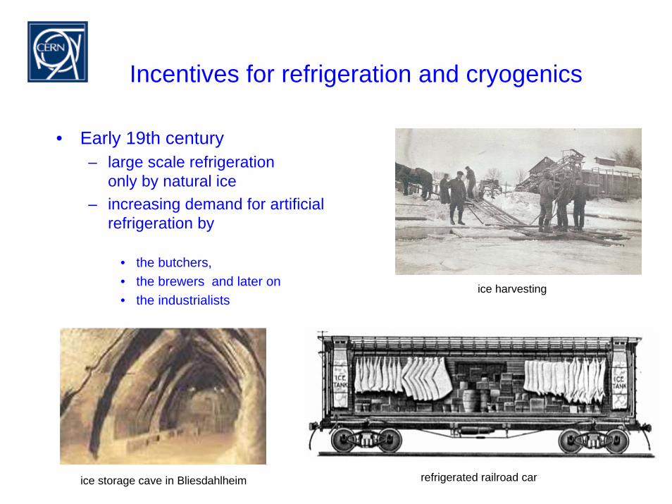
• Early 19th century– large scale refrigeration
only by natural ice– increasing demand for artificial
refrigeration by
• the butchers,• the brewers and later on• the industrialists
ice harvesting
refrigerated railroad car ice storage cave in Bliesdahlheim
Incentives for refrigeration and cryogenics
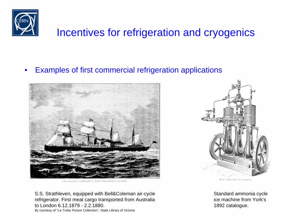
• Examples of first commercial refrigeration applications
S.S. Strathleven, equipped with Bell&Coleman air-cyclerefrigerator. First meat cargo transported from Australiato London 6.12.1879 - 2.2.1880.By courtesy of "La Trobe Picture Collection", State Library of Victoria
Standard ammonia cycle ice machine from York’s 1892 catalogue.
Braking the cryo-barrier I
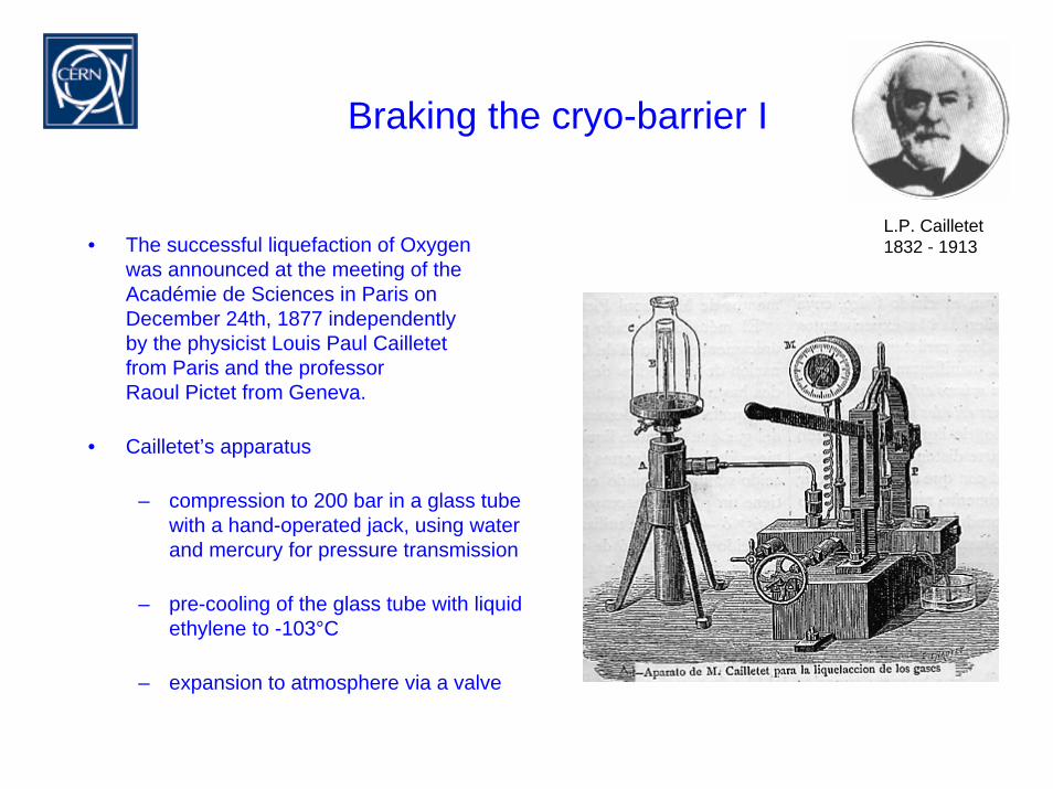
L.P. Cailletet 1832 - 1913• The successful liquefaction of Oxygen
was announced at the meeting of theAcadémie de Sciences in Paris on December 24th, 1877 independentlyby the physicist Louis Paul Cailletet from Paris and the professorRaoul Pictet from Geneva.
• Cailletet’s apparatus
– compression to 200 bar in a glass tube with a hand-operated jack, using waterand mercury for pressure transmission
– pre-cooling of the glass tube with liquidethylene to -103°C
– expansion to atmosphere via a valve
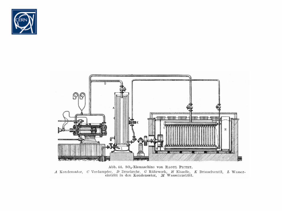
Braking the cryo-barrier II
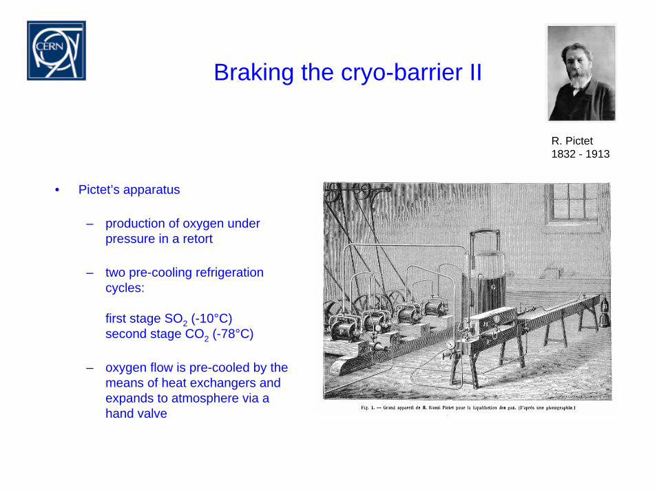
R. Pictet 1832 - 1913
• Pictet’s apparatus
– production of oxygen under pressure in a retort
– two pre-cooling refrigerationcycles:
first stage SO2 (-10°C)second stage CO2 (-78°C)
– oxygen flow is pre-cooled by themeans of heat exchangers andexpands to atmosphere via a hand valve
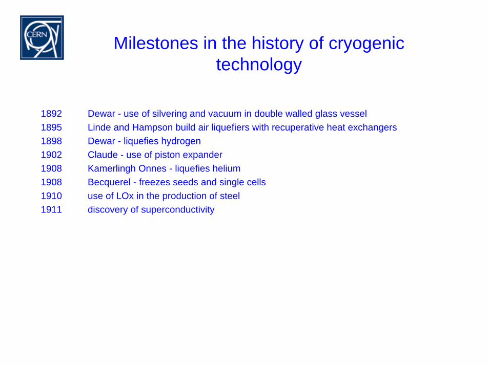
Milestones in the history of cryogenictechnology
1892 Dewar - use of silvering and vacuum in double walled glass vessel1895 Linde and Hampson build air liquefiers with recuperative heat exchangers1898 Dewar - liquefies hydrogen1902 Claude - use of piston expander1908 Kamerlingh Onnes - liquefies helium1908 Becquerel - freezes seeds and single cells1910 use of LOx in the production of steel1911 discovery of superconductivity
Thermo-dynamics
The magic of throttling - physicist’s explanation
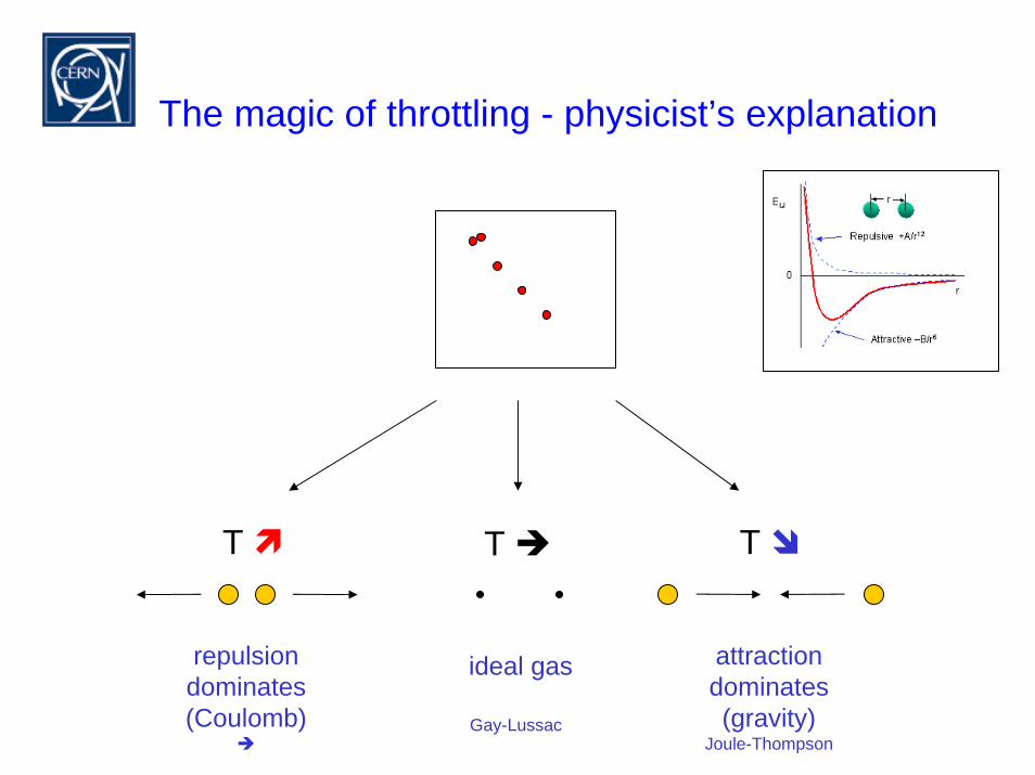
The magic of throttling - physicist’s explanation
T T T
repulsiondominates(Coulomb)
attractiondominates(gravity)
Joule-Thompson
ideal gas
Gay-Lussac
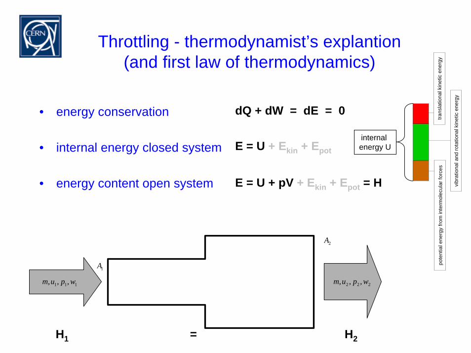
Throttling - thermodynamist’s explantion(and first law of thermodynamics)
• energy conservation
• internal energy closed system
• energy content open system
E = U + Ekin + Epot
dQ + dW = dE = 0
E = U + pV + Ekin + Epot = H
trans
latio
nal k
inet
ic e
nerg
y
vibr
atio
nal a
nd ro
tatio
nal k
inet
ic e
nerg
y
pote
ntia
l ene
rgy
from
inte
rmol
ecul
ar fo
rces
internal energy U
111 ,,, wpum
2A
1A
222 ,,, wpum
H1 = H2
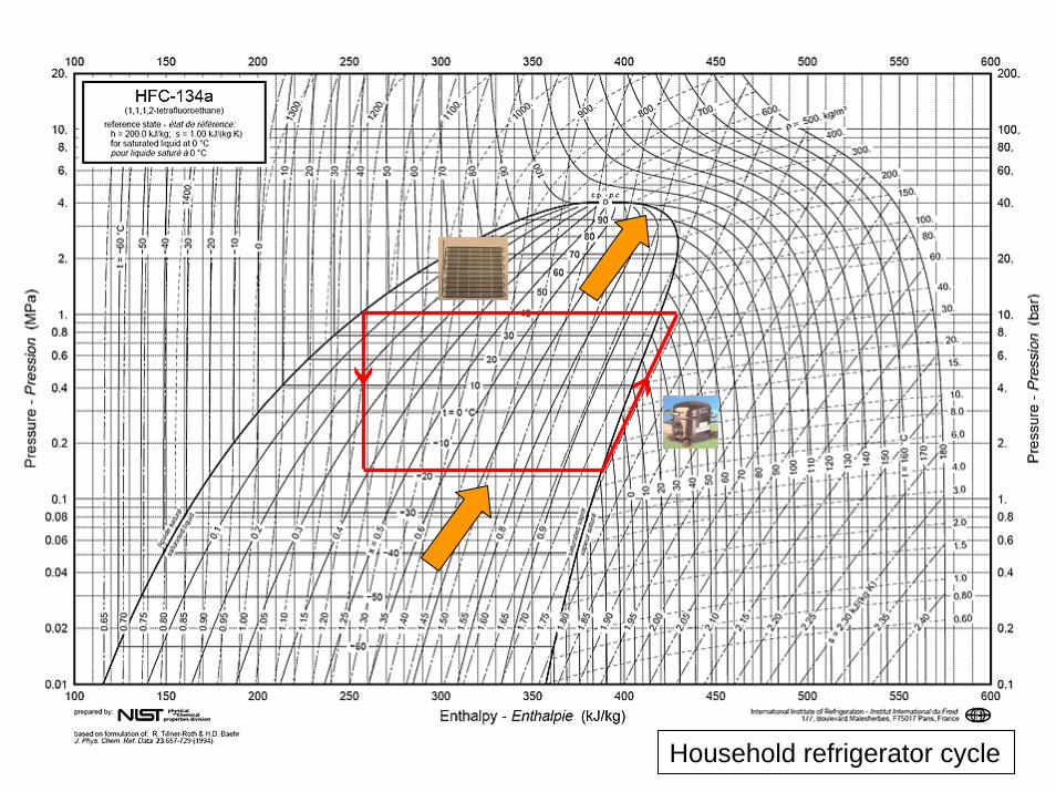
Household refrigerator cycle
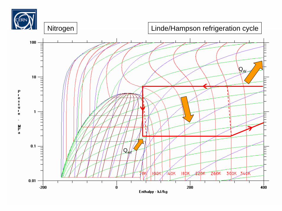
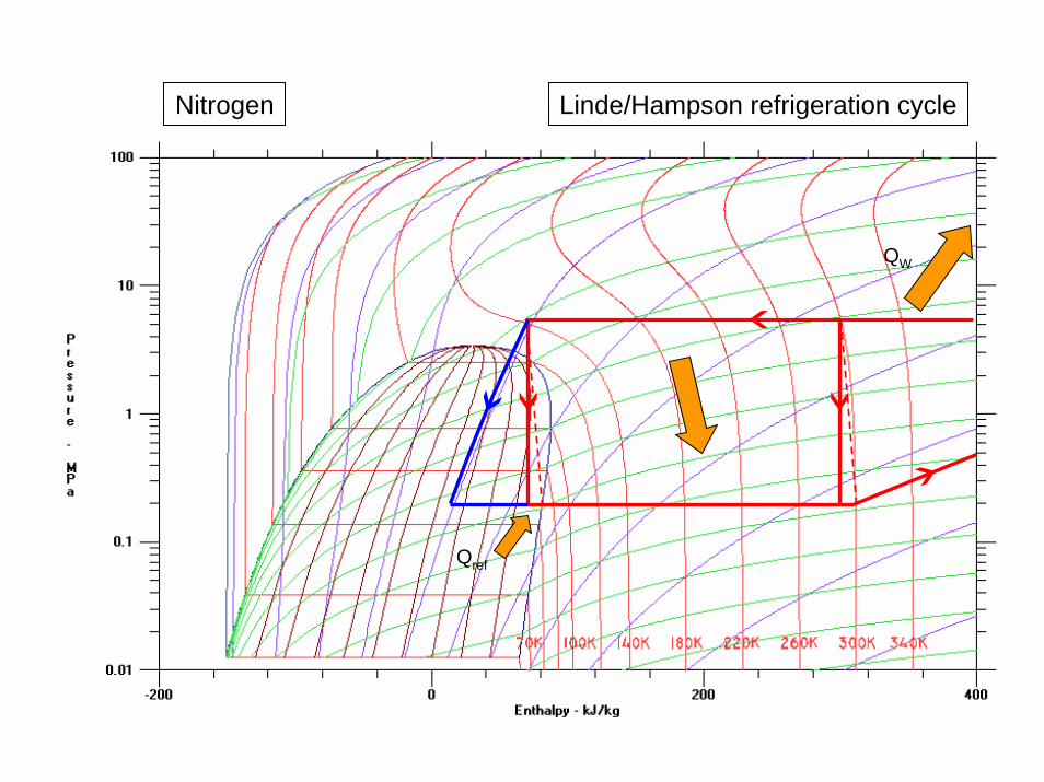
Nitrogen Linde/Hampson refrigeration cycle
Qref
QW
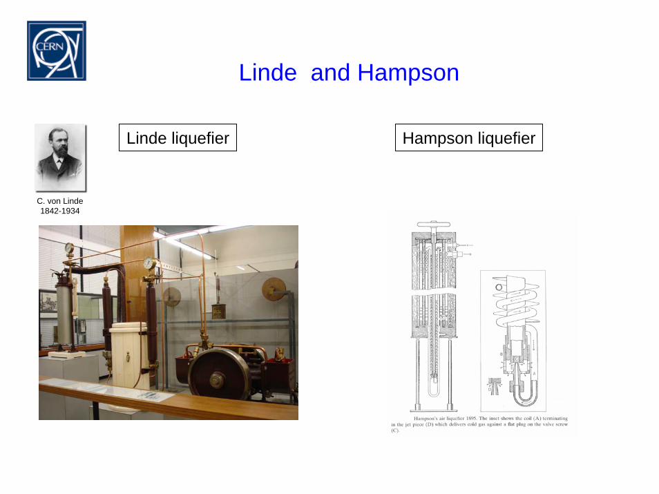
Linde and Hampson
Linde liquefier Hampson liquefier
C. von Linde1842-1934
Nitrogen Linde/Hampson refrigeration cycle
Qref
QW
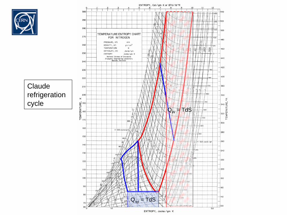
Qref = TdS
QW = TdS
Claude refrigeration cycle
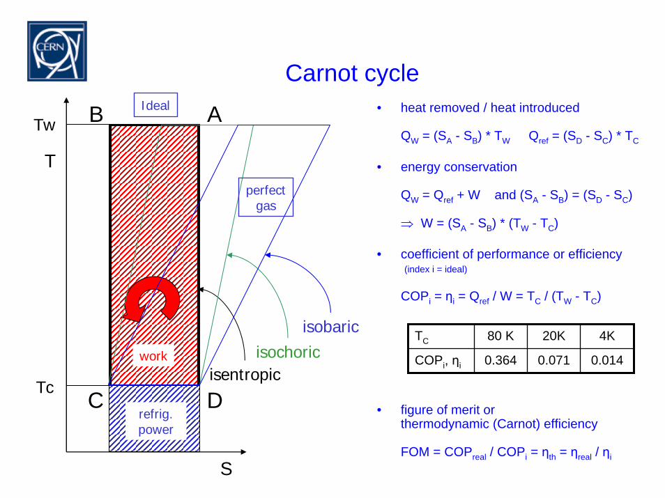
Carnot cycle• heat removed / heat introduced
QW = (SA - SB) * TW Qref = (SD - SC) * TC
• energy conservation
QW = Qref + W and (SA - SB) = (SD - SC)
⇒ W = (SA - SB) * (TW - TC)
• coefficient of performance or efficiency(index i = ideal)
COPi = ηi = Qref / W = TC / (TW - TC)
• figure of merit orthermodynamic (Carnot) efficiency
FOM = COPreal / COPi = ηth = ηreal / ηi
S
isentropic
refrig.power
work
Ideal AB
C D
TC 80 K 20K 4K
COPi, ηi 0.364 0.071 0.014isochoricisobaric
perfectgas
Tw
T
Tc
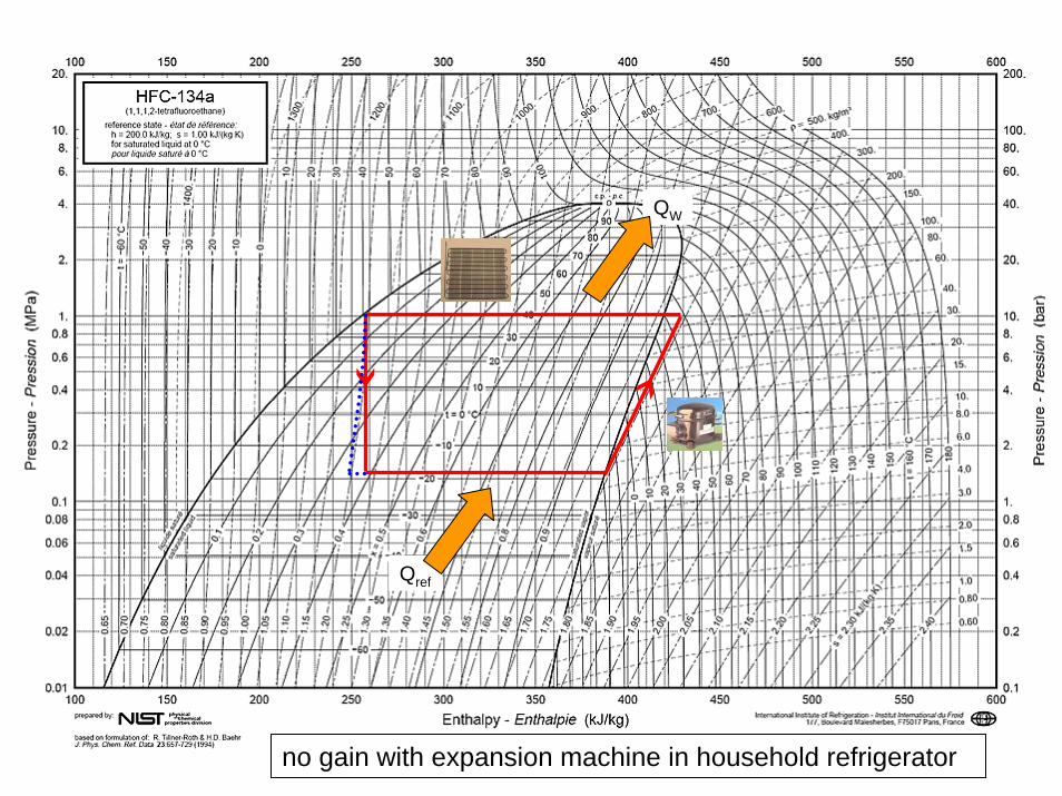
no gain with expansion machine in household refrigerator
Qref
QW
Summary - refrigeration
refrigeration can be achieved by
– contact with a colder surface
– throttling
– work extraction
refrigeration can reach lower temperatures by
– heat recovery

Cycles
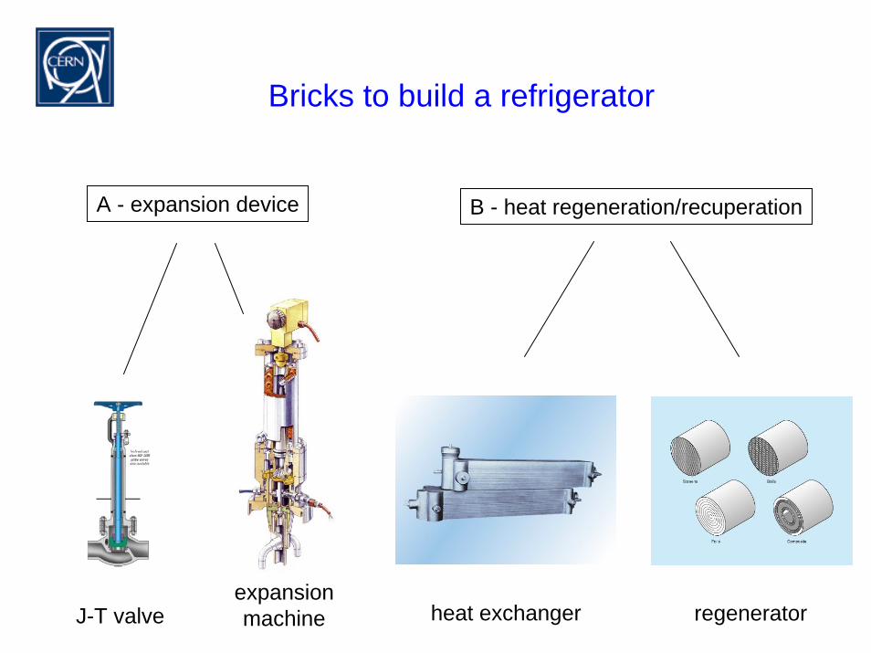
Bricks to build a refrigerator
A - expansion device B - heat regeneration/recuperation
expansionmachine heat exchanger regeneratorJ-T valve

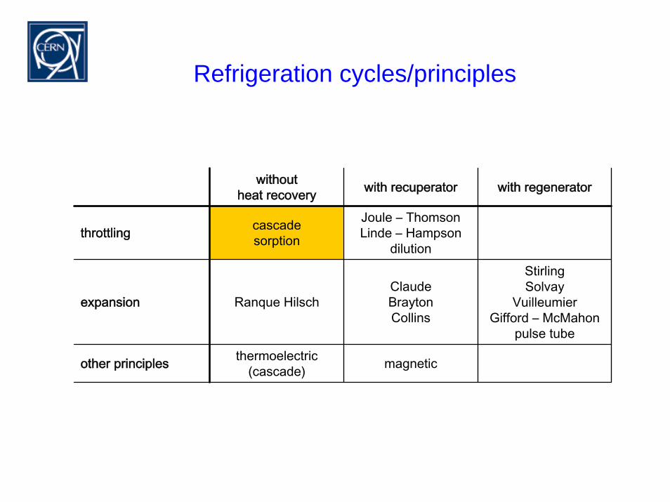
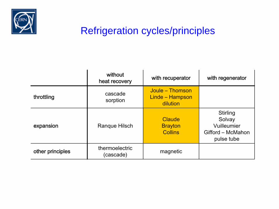
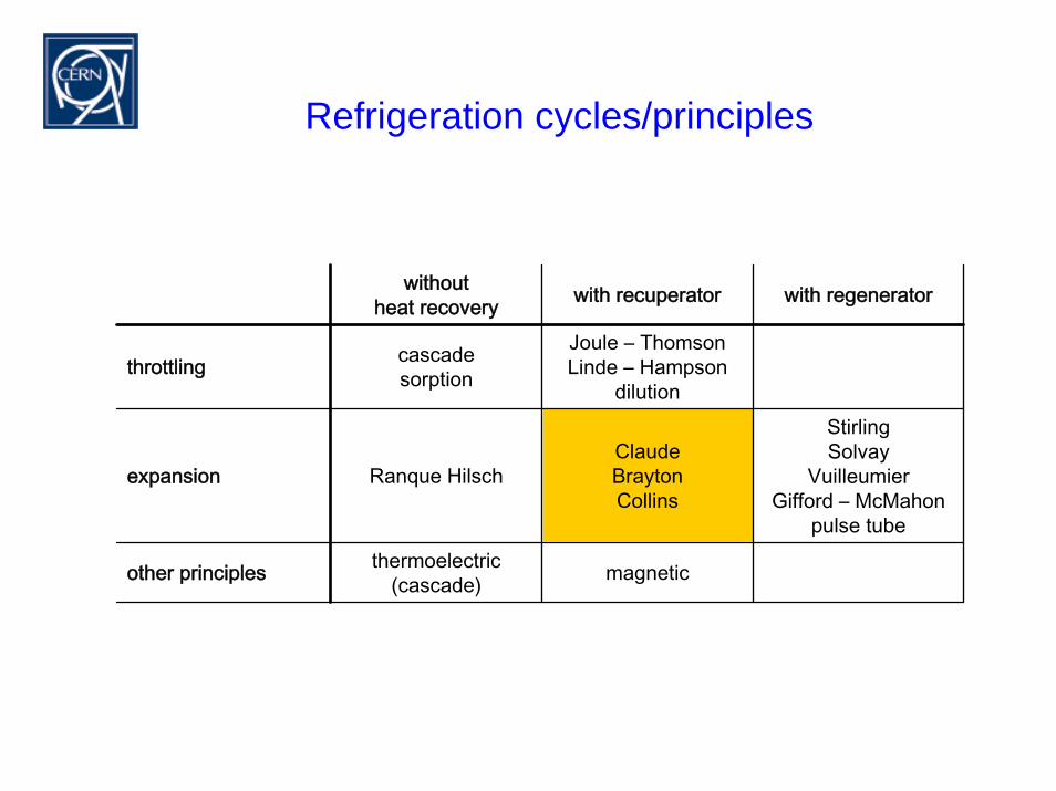
Refrigeration cycles/principles
withoutheat recovery with recuperator with regenerator
throttling cascadesorption
Joule – ThomsonLinde – Hampson
dilution
expansion Ranque HilschClaudeBraytonCollins
StirlingSolvay
VuilleumierGifford – McMahon
pulse tube
other principles thermoelectric (cascade) magnetic
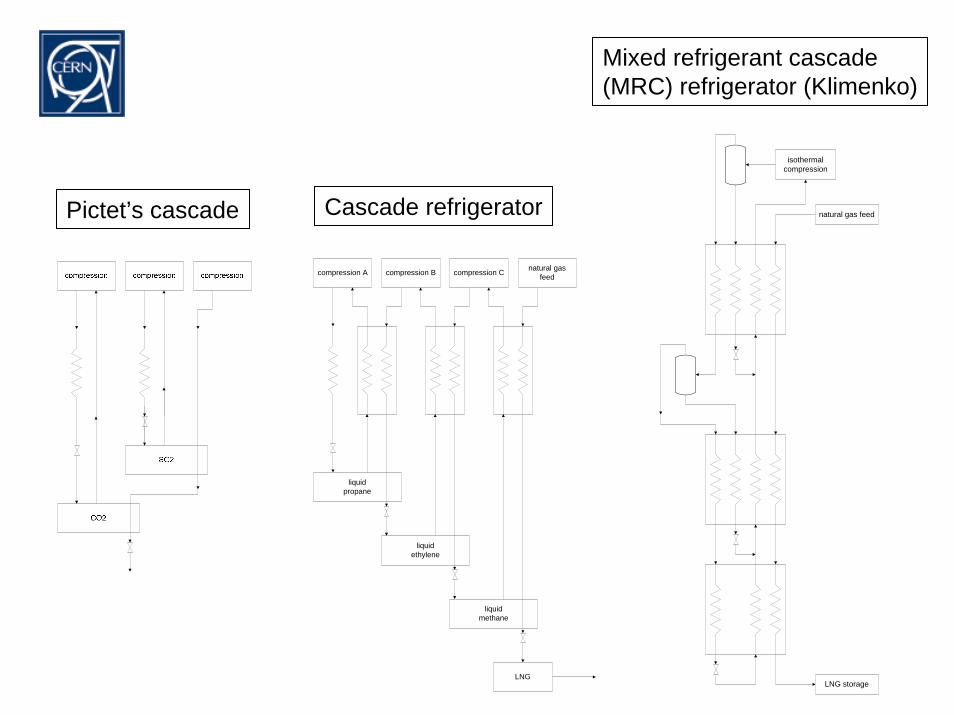
Mixed refrigerant cascade (MRC) refrigerator (Klimenko)
isothermalcompression
natural gas feed
LNG storage
Cascade refrigeratorPictet’s cascade
LNG
compression A
liquidpropane
compression B
liquidethylene
liquidmethane
natural gasfeedcompression C
Refrigeration cycles/principles
withoutheat recovery with recuperator with regenerator
throttling cascadesorption
Joule – ThomsonLinde – Hampson
dilution
expansion Ranque HilschClaudeBraytonCollins
StirlingSolvay
VuilleumierGifford – McMahon
pulse tube
other principles thermoelectric (cascade) magnetic
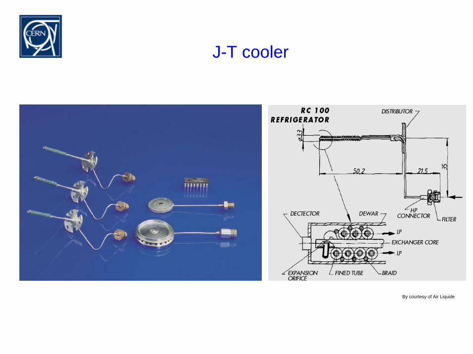
J-T cooler
By courtesy of Air Liquide
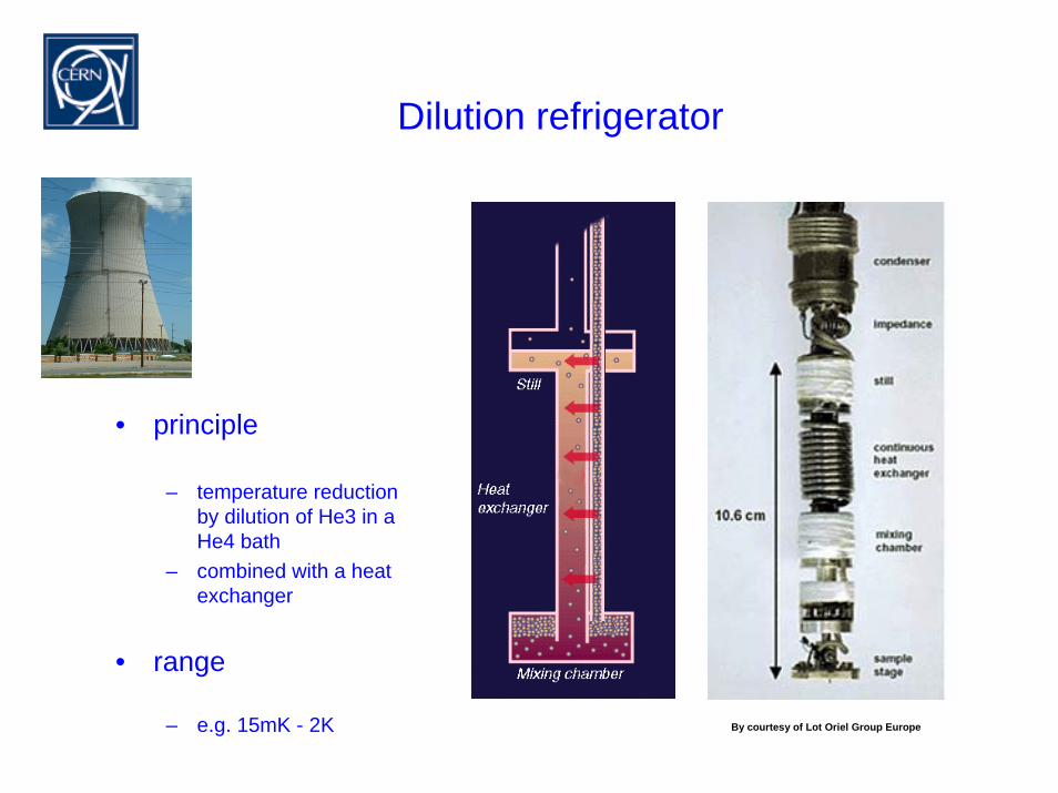
Dilution refrigerator
• principle
– temperature reductionby dilution of He3 in aHe4 bath
– combined with a heat exchanger
• range
– e.g. 15mK - 2K By courtesy of Lot Oriel Group Europe
Refrigeration cycles/principles
withoutheat recovery with recuperator with regenerator
throttling cascadesorption
Joule – ThomsonLinde – Hampson
dilution
expansion Ranque HilschClaudeBraytonCollins
StirlingSolvay
VuilleumierGifford – McMahon
pulse tube
other principles thermoelectric (cascade) magnetic
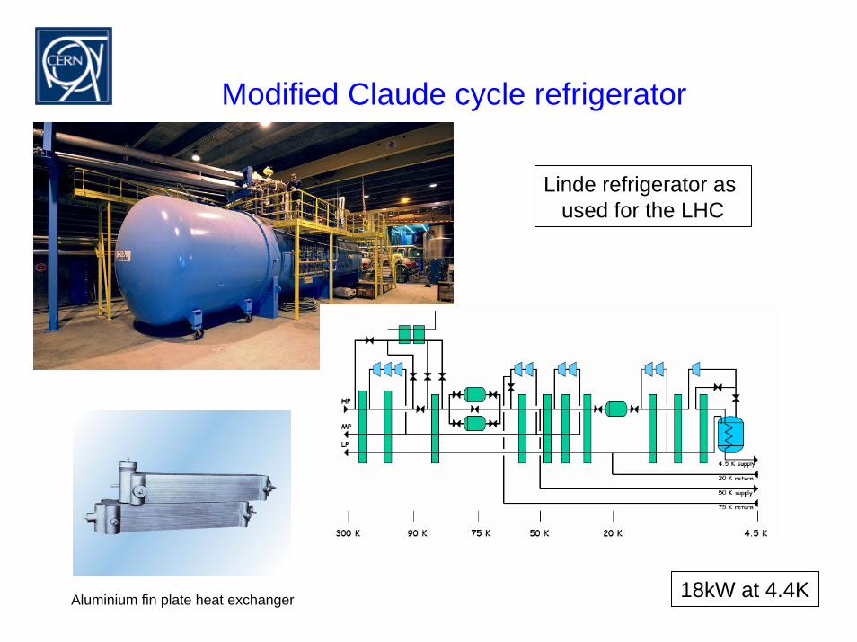
Modified Claude cycle refrigerator
Linde refrigerator as used for the LHC
18kW at 4.4KAluminium fin plate heat exchanger
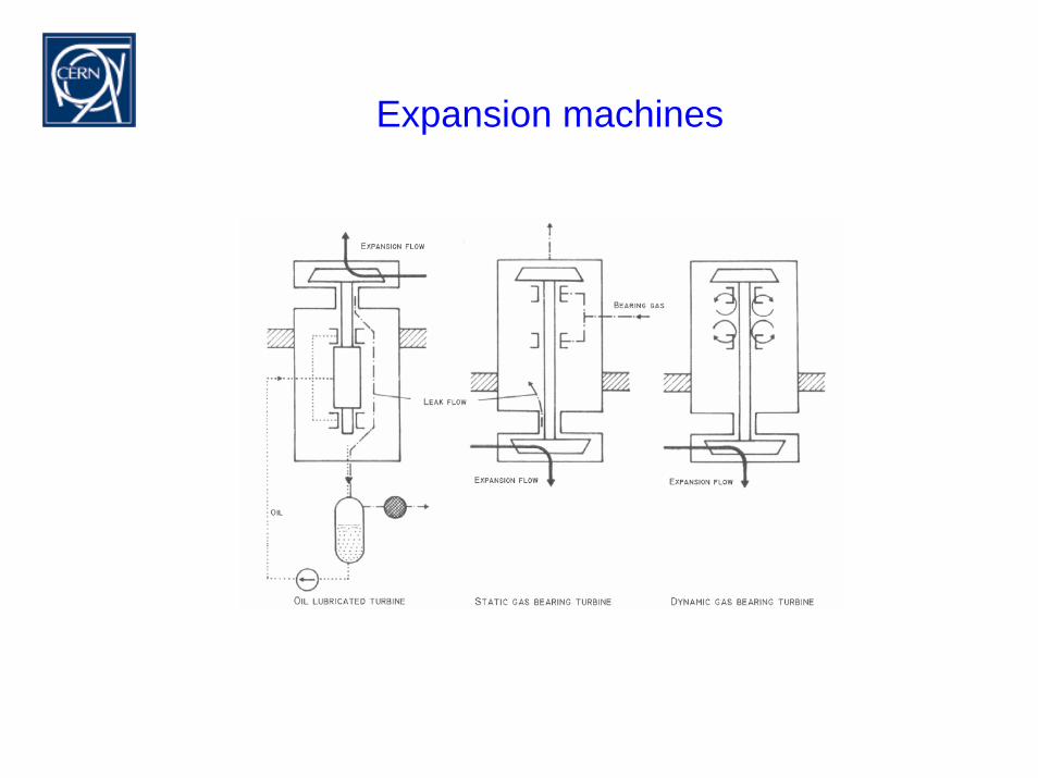
Expansion machines
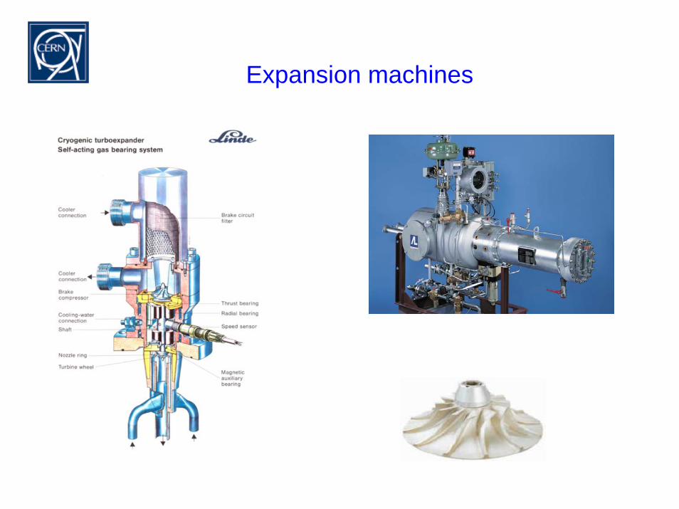
Expansion machines
Refrigeration cycles/principles
withoutheat recovery with recuperator with regenerator
throttling cascadesorption
Joule – ThomsonLinde – Hampson
dilution
expansion Ranque HilschClaudeBraytonCollins
StirlingSolvay
VuilleumierGifford – McMahon
pulse tube
other principles thermoelectric (cascade) magnetic
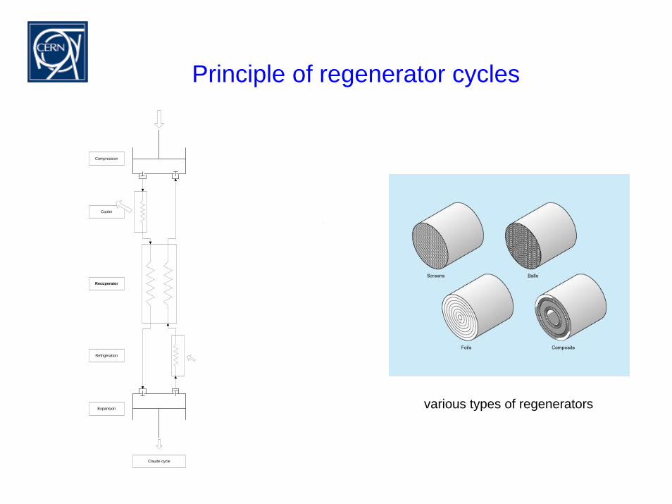
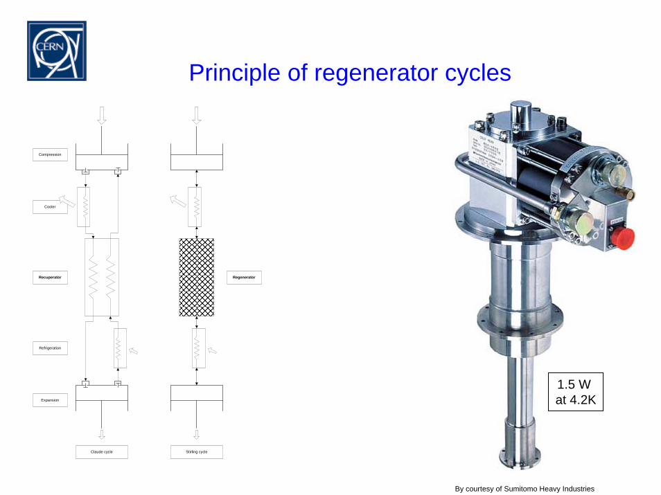
Principle of regenerator cycles
Compression
Cooler
Recuperator
Refrigeration
Expansion
Regenerator
HP LP HP LP
Solvay cycle Gifford - McMahon cycleStirling cycleClaude cycle
HP LP
pulse tube
Vol.
various types of regenerators
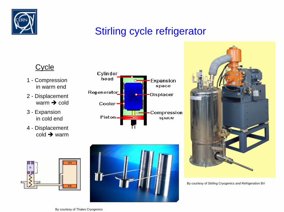
Stirling cycle refrigerator
Cycle1 - Compression
in warm end
2 - Displacementwarm cold
3 - Expansionin cold end
4 - Displacementcold warm
By courtesy of Stirling Cryogenics and Refrigeration BV
By courtesy of Thales Cryogenics
Principle of regenerator cycles
Compression
Cooler
Recuperator
Refrigeration
Expansion
Regenerator
HP LP HP LP
Solvay cycle Gifford - McMahon cycleStirling cycleClaude cycle
HP LP
pulse tube
Vol.
1.5 W at 4.2K
By courtesy of Sumitomo Heavy Industries
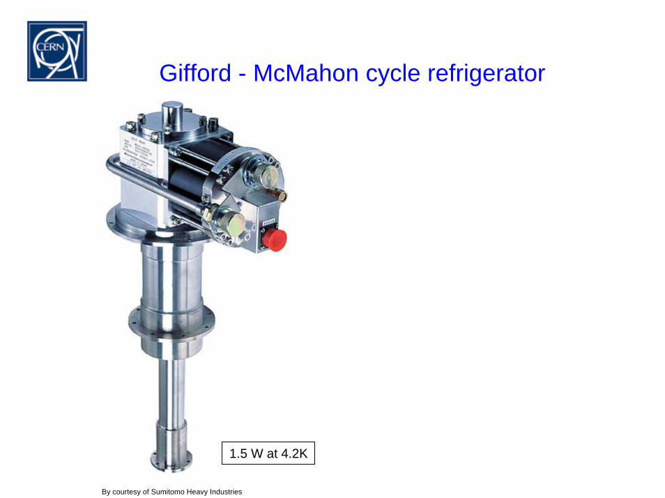
Gifford - McMahon cycle refrigerator
1.5 W at 4.2K
By courtesy of Sumitomo Heavy Industries
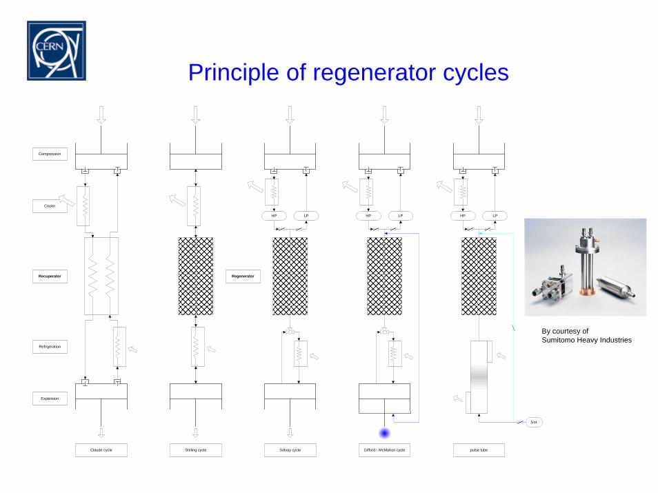
Principle of regenerator cycles
Compression
Cooler
Recuperator
Refrigeration
Expansion
Regenerator
HP LP HP LP
Solvay cycle Gifford - McMahon cycleStirling cycleClaude cycle
HP LP
pulse tube
Vol.
By courtesy ofSumitomo Heavy Industries
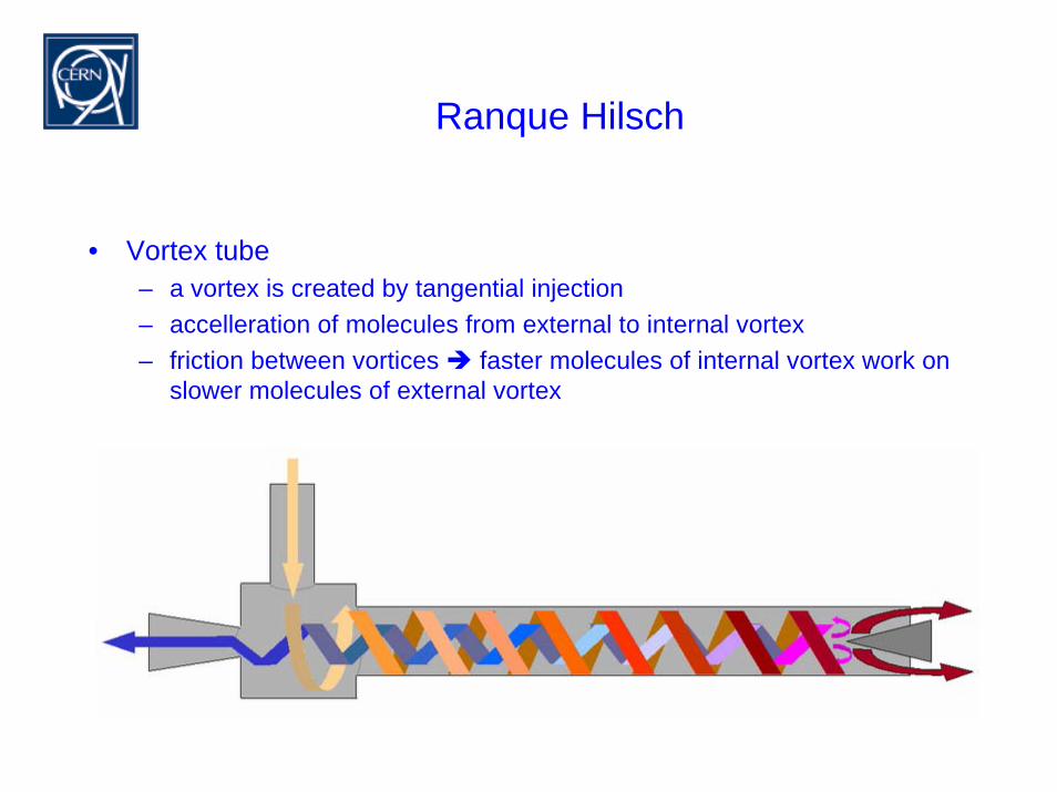
Ranque Hilsch
• Vortex tube– a vortex is created by tangential injection– accelleration of molecules from external to internal vortex– friction between vortices faster molecules of internal vortex work on
slower molecules of external vortex
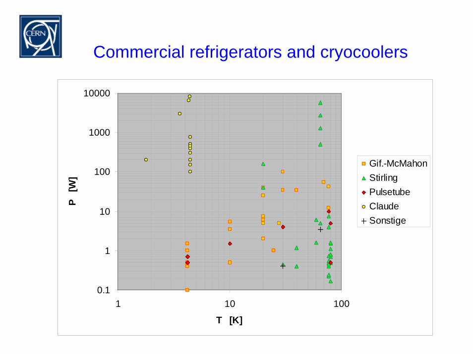
Commercial refrigerators and cryocoolers
0.1
1
10
100
1000
10000
1 10 100
T [K]
P [
W]
Gif.-McMahonStirlingPulsetubeClaudeSonstige
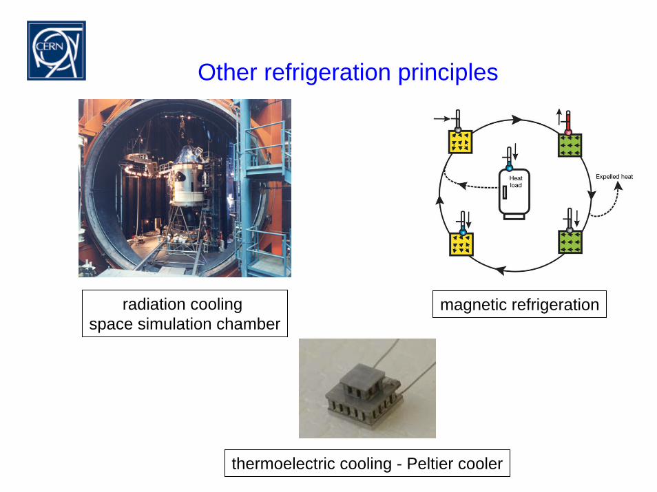
Other refrigeration principles
radiation cooling space simulation chamber
magnetic refrigeration
thermoelectric cooling - Peltier cooler
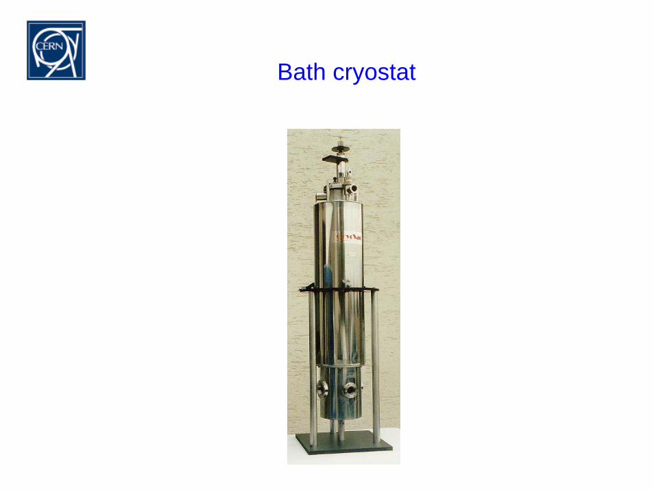
Bath cryostat

Day 2
Introduction to Cryogenic Engineering
MONDAY From History to Modern Refrigeration Cycles (G. Perinić)
TUESDAY Standard Components, Cryogenic Design (G. Perinić)
WEDNESDAY Heat Transfer and Insulation (G. Vandoni)
THURSDAY Safety, Information Resources (G. Perinić)
FRIDAY Applications of Cryogenic Engineering (T. Niinikoski)
Refrigerants
Standard Cryostats
Material properties
Specifying a refrigeration task
Manufacturing techniques and selected hardware
components
Refrigerants
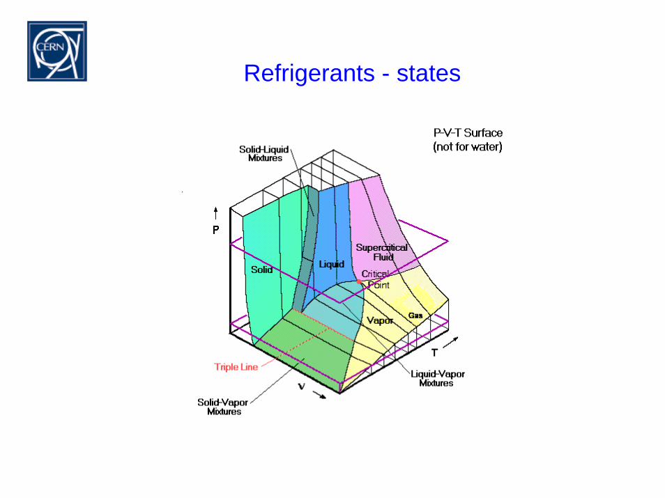
Refrigerants - states
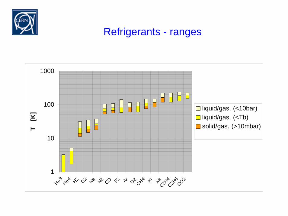
Refrigerants - ranges
1
10
100
1000
He3He4 H2 D2 Ne N2CO F2 ArO2CH4 Kr XeC2H4C2H6CO2
T [
K] liquid/gas. (<10bar)
liquid/gas. (<Tb)solid/gas. (>10mbar)
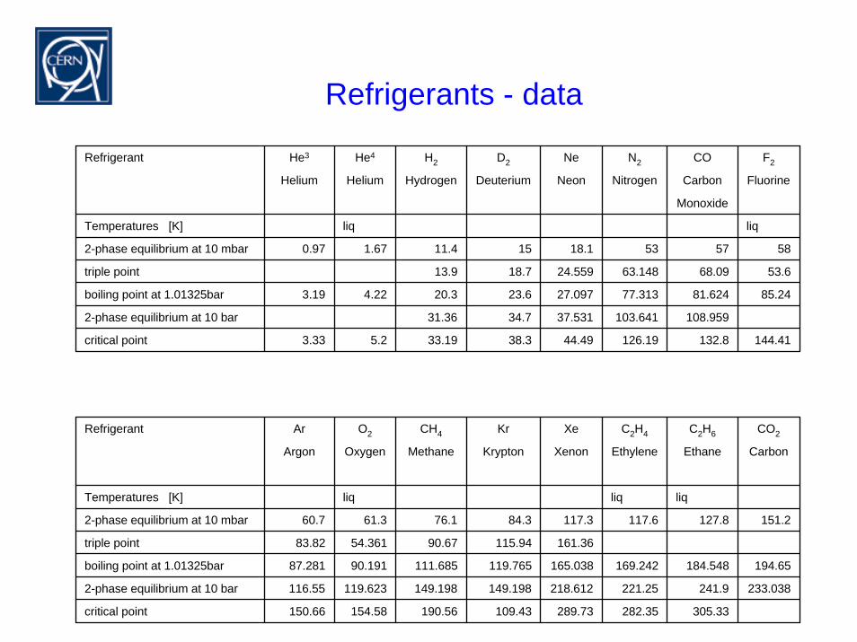
Refrigerants - data
Refrigerant He3 He4 H2 D2 Ne N2 CO F2
Helium Helium Hydrogen Deuterium Neon Nitrogen Carbon Fluorine
Monoxide
Temperatures [K] liq liq
2-phase equilibrium at 10 mbar 0.97 1.67 11.4 15 18.1 53 57 58
triple point 13.9 18.7 24.559 63.148 68.09 53.6
boiling point at 1.01325bar 3.19 4.22 20.3 23.6 27.097 77.313 81.624 85.24
2-phase equilibrium at 10 bar 31.36 34.7 37.531 103.641 108.959
critical point 3.33 5.2 33.19 38.3 44.49 126.19 132.8 144.41
Refrigerant Ar O2 CH4 Kr Xe C2H4 C2H6 CO2
Argon Oxygen Methane Krypton Xenon Ethylene Ethane Carbon
Temperatures [K] liq liq liq
2-phase equilibrium at 10 mbar 60.7 61.3 76.1 84.3 117.3 117.6 127.8 151.2
triple point 83.82 54.361 90.67 115.94 161.36
boiling point at 1.01325bar 87.281 90.191 111.685 119.765 165.038 169.242 184.548 194.65
2-phase equilibrium at 10 bar 116.55 119.623 149.198 149.198 218.612 221.25 241.9 233.038
critical point 150.66 154.58 190.56 109.43 289.73 282.35 305.33
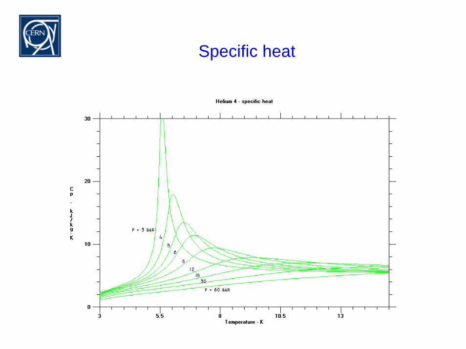
Specific heat
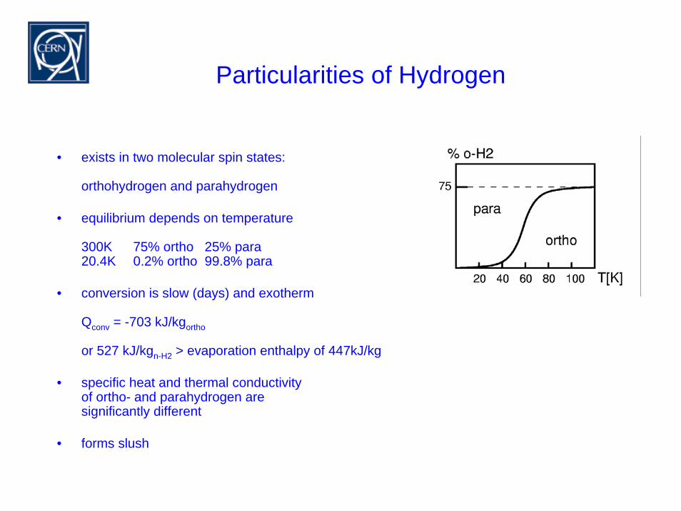
Particularities of Hydrogen
• exists in two molecular spin states:
orthohydrogen and parahydrogen
• equilibrium depends on temperature
300K 75% ortho 25% para20.4K 0.2% ortho 99.8% para
• conversion is slow (days) and exotherm
Qconv = -703 kJ/kgortho
or 527 kJ/kgn-H2 > evaporation enthalpy of 447kJ/kg
• specific heat and thermal conductivityof ortho- and parahydrogen are significantly different
• forms slush
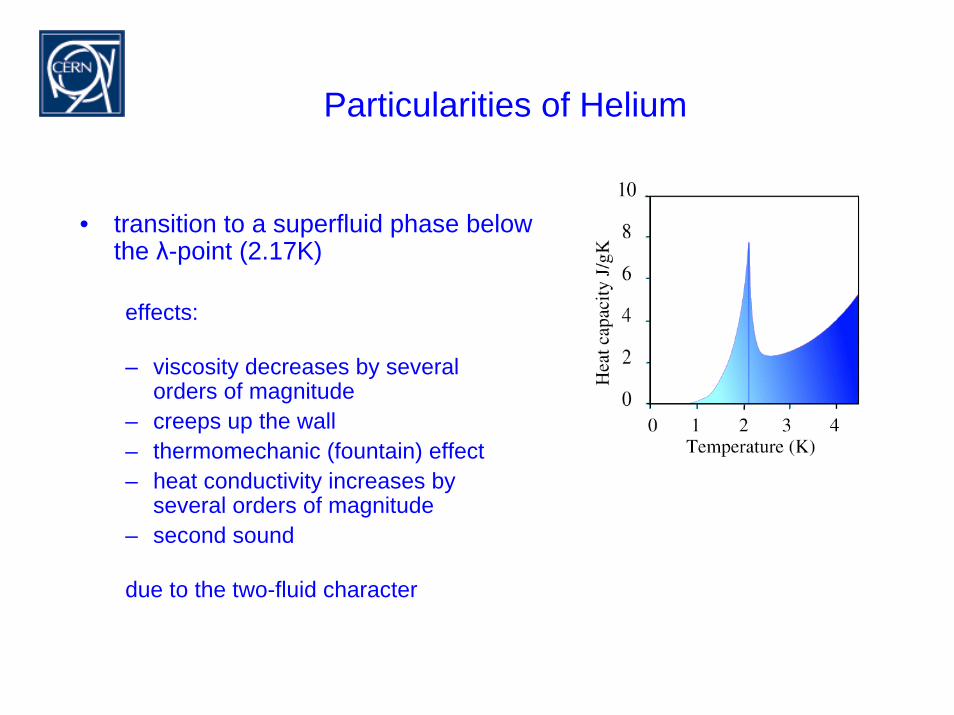
Particularities of Helium
• transition to a superfluid phase below the λ-point (2.17K)
effects:
– viscosity decreases by several orders of magnitude
– creeps up the wall– thermomechanic (fountain) effect– heat conductivity increases by
several orders of magnitude– second sound
due to the two-fluid character
StandardCryostats
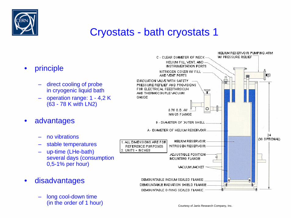
Cryostats - bath cryostats 1
• principle
– direct cooling of probe in cryogenic liquid bath
– operation range: 1 - 4,2 K(63 - 78 K with LN2)
• advantages
– no vibrations– stable temperatures– up-time (LHe-bath)
several days (consumption0,5-1% per hour)
• disadvantages
– long cool-down time(in the order of 1 hour)
Courtesy of Janis Research Company, Inc.
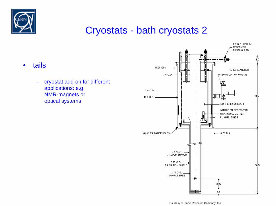
Cryostats - bath cryostats 2
• tails
– cryostat add-on for differentapplications: e.g.NMR-magnets or optical systems
Courtesy of Janis Research Company, Inc.
Cryostats - bath cryostats 3
Probe
Zwischenrauminterspace
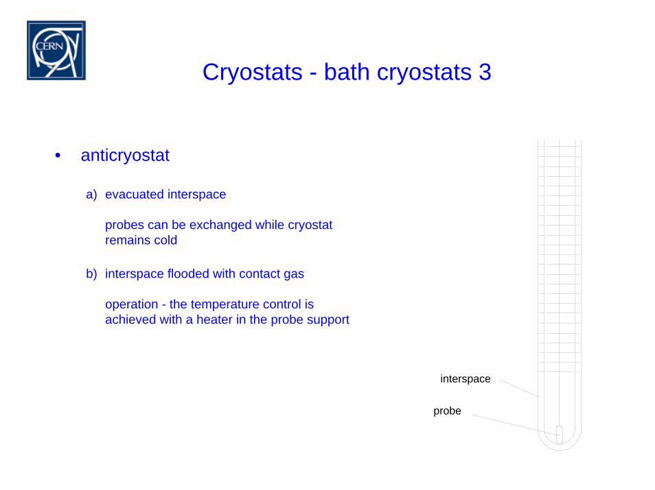
probe
• anticryostat
a) evacuated interspace
probes can be exchanged while cryostat remains cold
b) interspace flooded with contact gas
operation - the temperature control isachieved with a heater in the probe support
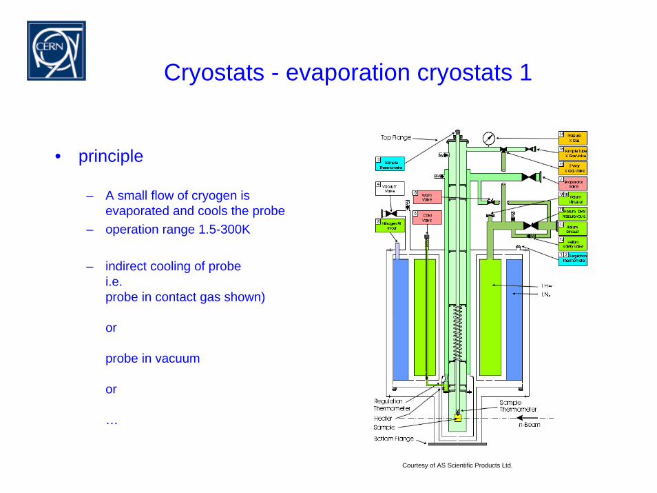
Cryostats - evaporation cryostats 1
• principle
– A small flow of cryogen isevaporated and cools the probe
– operation range 1.5-300K
– indirect cooling of probei.e.probe in contact gas shown)
or
probe in vacuum
or
…
Courtesy of AS Scientific Products Ltd.
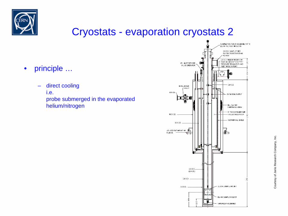
Cryostats - evaporation cryostats 2
• principle …
– direct coolingi.e.probe submerged in the evaporatedhelium/nitrogen
Cou
rtesy
ofJa
nis
Res
earc
h C
ompa
ny, I
nc.
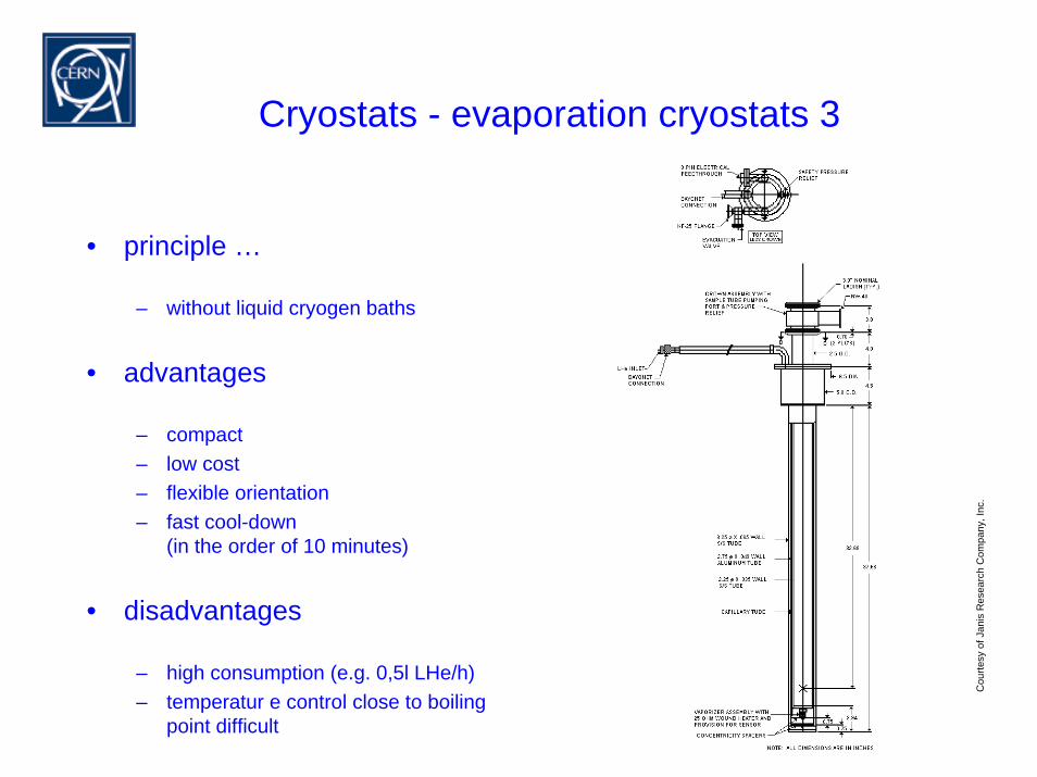
Cryostats - evaporation cryostats 3
• principle …
– without liquid cryogen baths
• advantages
– compact– low cost– flexible orientation– fast cool-down
(in the order of 10 minutes)
• disadvantages
– high consumption (e.g. 0,5l LHe/h)– temperatur e control close to boiling
point difficult
Cou
rtesy
ofJa
nis
Res
earc
h C
ompa
ny, I
nc.
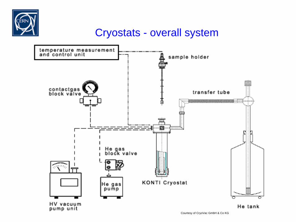
Cryostats - overall system
Courtesy of CryoVac GmbH & Co KG
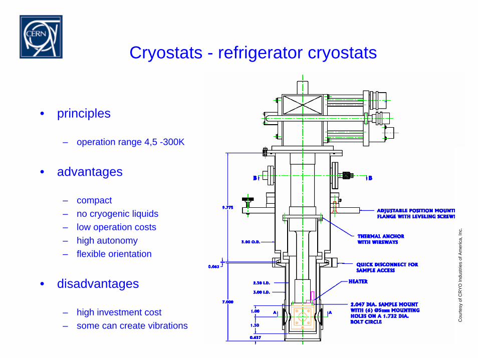
Cryostats - refrigerator cryostats
Cou
rtesy
ofC
RYO
Indu
strie
s of
Am
eric
a, In
c.
• principles
– operation range 4,5 -300K
• advantages
– compact– no cryogenic liquids– low operation costs– high autonomy– flexible orientation
• disadvantages
– high investment cost– some can create vibrations

Specification
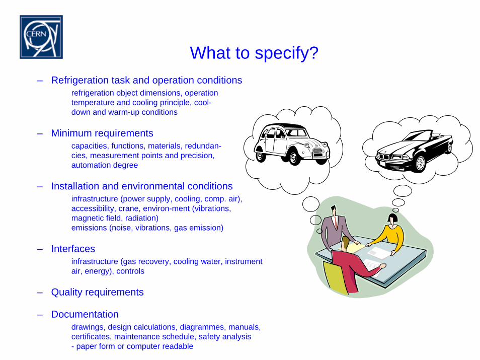
What to specify?– Refrigeration task and operation conditions
refrigeration object dimensions, operationtemperature and cooling principle, cool-down and warm-up conditions
– Minimum requirementscapacities, functions, materials, redundan-cies, measurement points and precision, automation degree
– Installation and environmental conditionsinfrastructure (power supply, cooling, comp. air), accessibility, crane, environ-ment (vibrations, magnetic field, radiation)emissions (noise, vibrations, gas emission)
– Interfacesinfrastructure (gas recovery, cooling water, instrument air, energy), controls
– Quality requirements
– Documentationdrawings, design calculations, diagrammes, manuals, certificates, maintenance schedule, safety analysis- paper form or computer readable
Specification - typical quality requirements
• Materials
– e.g. special material specifications– material certificates
• Joining techniques
– requirements for weldments– requirements for joints
• Surface properties
– free of ferritic impurities– dirt, grease, weld XXX
• Leak ratese.g.< 10-8 mbarls-1 individual welds< 10-7 - 10-6 mbarls-1 overall leakrate He->Vac< 10-6 - 10-5 mbarls-1 overall leakrate air->Vac< 10-4 mbarls-1 valve seats< 10-4 mbarls-1 flanges with non-metallic
seals
• Thermal lossesz.B.0,3-2,3% /24h liq. helium transp. vessel0,1-0,5% /24h liquid nitrogen tank0,5-2 W/m liquid nitrogen transfer line5-500 mW/m shielded helium transfer
line

Materials
Materials - selection criteria
• mechanical strength
– σ0.2, σB, E, δ, α
• working properties
– forming, extrusion, welding
• further properties
– magnetic properties., electric properties
• thermal properties
– heat conductivity, heat capacity, thermal contraction
• surface properties
– corr. resist., emissivity, spec. surf. area, outgassing
• oeconomic properties
– price, availability
Materials - selection criteria
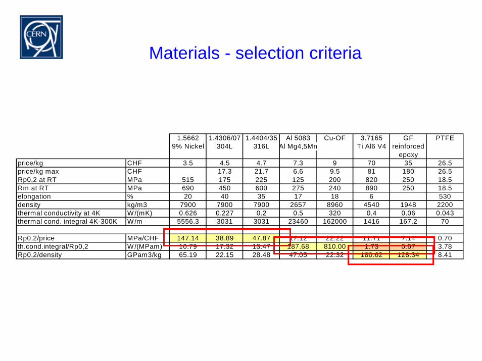
1.5662 1.4306/07 1.4404/35 Al 5083 Cu-OF 3.7165 GF PTFE9% Nickel 304L 316L Al Mg4,5Mn Ti Al6 V4 reinforced
epoxyprice/kg CHF 3.5 4.5 4.7 7.3 9 70 35 26.5price/kg max CHF 17.3 21.7 6.6 9.5 81 180 26.5Rp0,2 at RT MPa 515 175 225 125 200 820 250 18.5Rm at RT MPa 690 450 600 275 240 890 250 18.5elongation % 20 40 35 17 18 6 530density kg/m3 7900 7900 7900 2657 8960 4540 1948 2200thermal conductivity at 4K W/(mK) 0.626 0.227 0.2 0.5 320 0.4 0.06 0.043thermal cond. integral 4K-300K W/m 5556.3 3031 3031 23460 162000 1416 167.2 70
Rp0,2/price MPa/CHF 147.14 38.89 47.87 17.12 22.22 11.71 7.14 0.70th.cond.integral/Rp0,2 W/(MPam) 10.79 17.32 13.47 187.68 810.00 1.73 0.67 3.78Rp0,2/density GPam3/kg 65.19 22.15 28.48 47.05 22.32 180.62 128.34 8.41
Materials - thermal properties
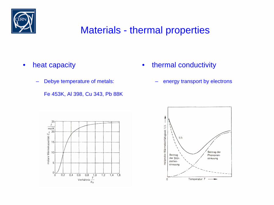
• heat capacity
– Debye temperature of metals:
Fe 453K, Al 398, Cu 343, Pb 88K
• thermal conductivity
– energy transport by electrons
Materials - steels
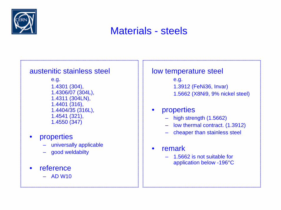
austenitic stainless steele.g.1.4301 (304), 1.4306/07 (304L), 1.4311 (304LN), 1.4401 (316), 1.4404/35 (316L), 1.4541 (321), 1.4550 (347)
• properties– universally applicable– good weldabilty
• reference– AD W10
low temperature steele.g.1.3912 (FeNi36, Invar)1.5662 (X8Ni9, 9% nickel steel)
• properties– high strength (1.5662)– low thermal contract. (1.3912)– cheaper than stainless steel
• remark– 1.5662 is not suitable for
application below -196°C
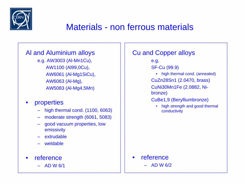
Materials - non ferrous materials
Al and Aluminium alloyse.g. AW3003 (Al-Mn1Cu),
AW1100 (Al99,0Cu), AW6061 (Al-Mg1SiCu), AW6063 (Al-Mg), AW5083 (Al-Mg4,5Mn)
• properties– high thermal cond. (1100, 6063)– moderate strength (6061, 5083)– good vacuum properties, low
emissivity– extrudable– weldable
• reference– AD W 6/1
Cu and Copper alloyse.g.SF-Cu (99.9)
• high thermal cond. (annealed)CuZn28Sn1 (2.0470, brass)CuNi30Mn1Fe (2.0882, Ni-bronze)CuBe1,9 (Berylliumbronze)
• high strength and good thermal conductivity
• reference– AD W 6/2
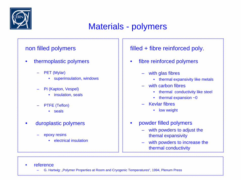
Materials - polymers
non filled polymers
• thermoplastic polymers
– PET (Mylar)• superinsulation, windows
– PI (Kapton, Vespel)• insulation, seals
– PTFE (Teflon)• seals
• duroplastic polymers
– epoxy resins• electrical insulation
filled + fibre reinforced poly.
• fibre reinforced polymers
– with glas fibres• thermal expansivity like metals
– with carbon fibres• thermal conductivity like steel• thermal expansion ~0
– Kevlar fibres• low weight
• powder filled polymers– with powders to adjust the
themal expansivity– with powders to increase the
thermal conductivity
• reference– G. Hartwig: „Polymer Properties at Room and Cryogenic Temperatures“, 1994, Plenum Press
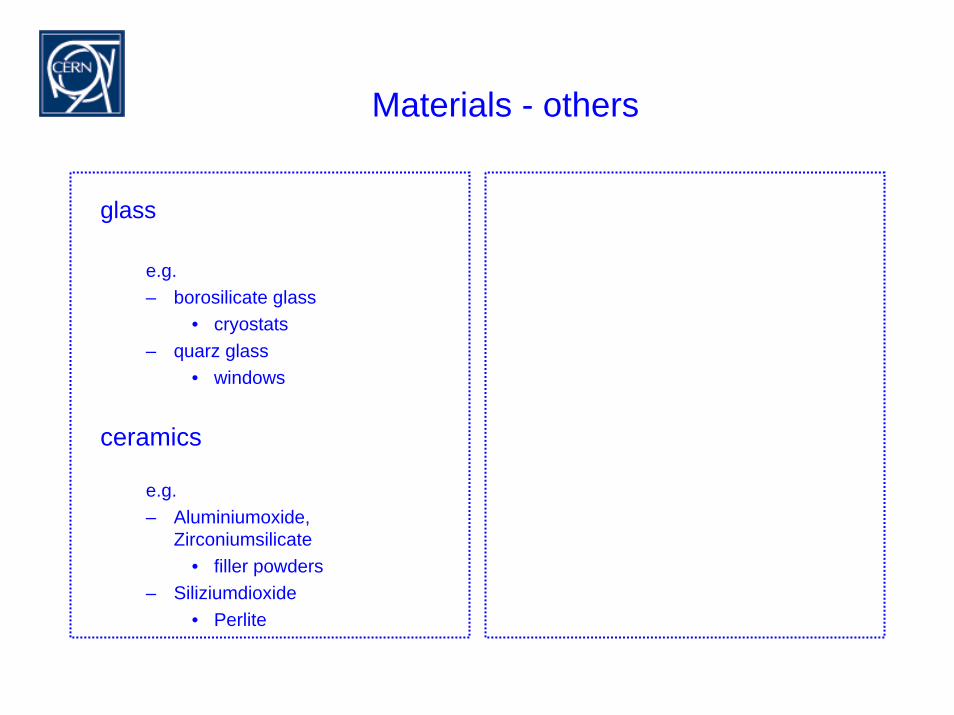
Materials - others
glass
e.g.– borosilicate glass
• cryostats– quarz glass
• windows
ceramics
e.g.– Aluminiumoxide,
Zirconiumsilicate• filler powders
– Siliziumdioxide• Perlite
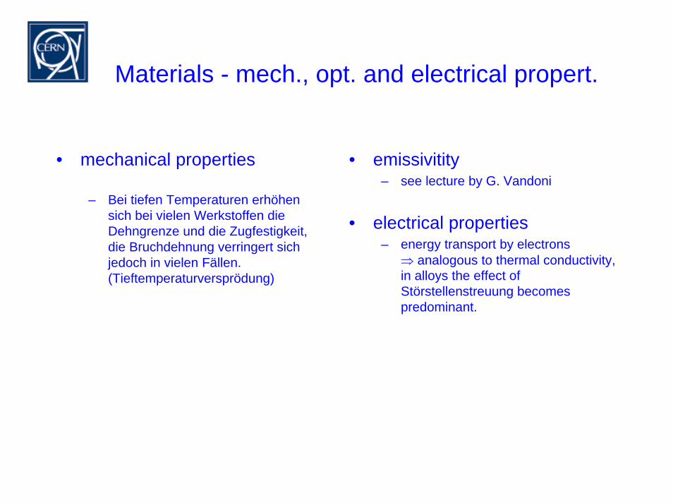
Materials - mech., opt. and electrical propert.
• mechanical properties
– Bei tiefen Temperaturen erhöhensich bei vielen Werkstoffen dieDehngrenze und die Zugfestigkeit, die Bruchdehnung verringert sichjedoch in vielen Fällen.(Tieftemperaturversprödung)
• emissivitity– see lecture by G. Vandoni
• electrical properties– energy transport by electrons
⇒ analogous to thermal conductivity,in alloys the effect ofStörstellenstreuung becomespredominant.

Techniquesand
SelectedHardware
Methoden und Bauelemente
• Joining technique and seals
• Valves
• Pipework and transfer lines
• Radiation shields
• Adsorbers
• Heaters
• Instrumentation
• Vacuum technique
Joining techniques - overview
• glueing
• electrical feed throughs• electrical insulation• thermal contacts
e.g. sensor attachement
• e.g.Araldite CW1304GB/HY1300GB,Eccobond 285 + Härter 24LV,Epo-Tek T7110,Poxycomet F,Scotch-Weld DP190,Stycast 2850FT + hardener 9,
• welding (TIG)• advantage - excellent leak tightness• for precision manufacturing - electron
beam welding• material transitions with friction
welded joints• attention - copper forms bubbles• provide for eventual cuts
• soldering– hard soldering
• thermal expansivity to be considered• good for copper - stainless steel joints• disadvantage - ageing possible
– soft soldering• e.g. In97-Ag3, In52-Sn48• attention - standard Sn60-Pb40 soft
solder becomes brittle at low temp.• not applicable for stainless steel• special soft solder exists:
– non superconducting– with low thermo-electric potent.
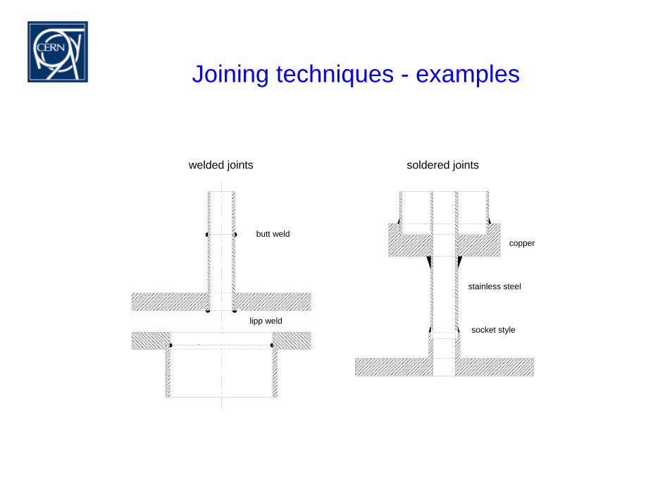
Joining techniques - examples
Schweissverbindungen Hartlötverbindungen
Stossnaht
Lippenschweissnaht
Innenliegende Schweissnaht
Kupfer
Edelstahl
Muffenausführung
welded joints soldered joints
butt weld
lipp weld
stainless steel
socket style
copper
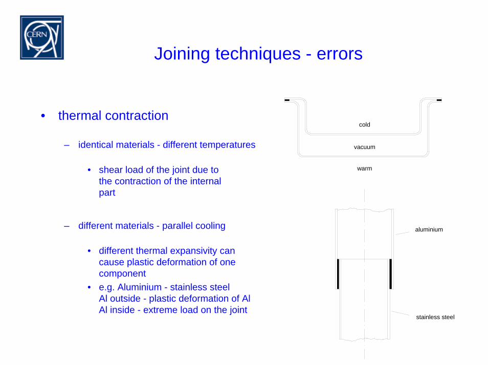
Joining techniques - errors
kalt
warm
Vakuum
• thermal contraction
– identical materials - different temperatures
• shear load of the joint due to the contraction of the internalpart
– different materials - parallel cooling
• different thermal expansivity cancause plastic deformation of onecomponent
• e.g. Aluminium - stainless steelAl outside - plastic deformation of AlAl inside - extreme load on the joint
cold
warm
vacuum
Aluminium
Edelstahl
aluminium
stainless steel
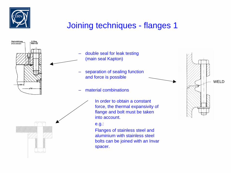
Joining techniques - flanges 1
– double seal for leak testing(main seal Kapton)
– separation of sealing function and force is possible
– material combinations
In order to obtain a constant force, the thermal expansivity offlange and bolt must be takeninto account.e.g.:Flanges of stainless steel andaluminium with stainless steelbolts can be joined with an Invar spacer.
WELD
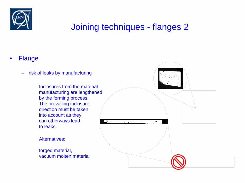
Joining techniques - flanges 2
• Flange
– risk of leaks by manufacturing
Inclosures from the materialmanufacturing are lengthenedby the forming process. The prevailing inclosuredirection must be takeninto account as theycan otherways leadto leaks.
Alternatives:
forged material,vacuum molten material
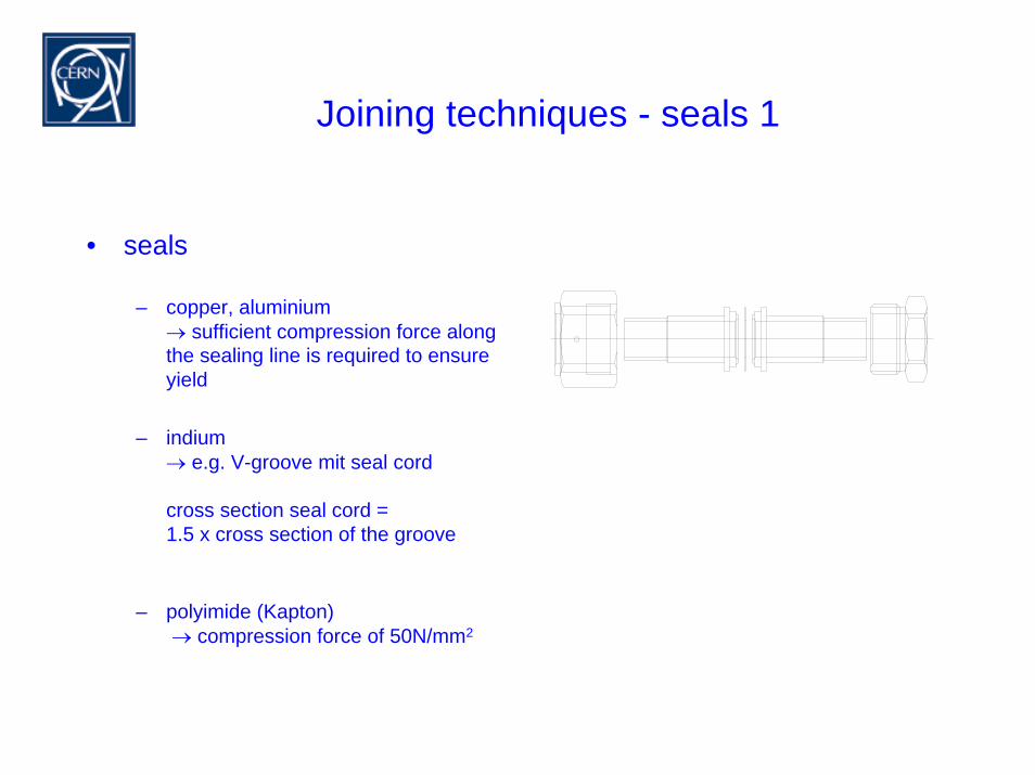
Joining techniques - seals 1
• seals
– copper, aluminium→ sufficient compression force alongthe sealing line is required to ensureyield
– indium→ e.g. V-groove mit seal cord
cross section seal cord = 1.5 x cross section of the groove
– polyimide (Kapton)→ compression force of 50N/mm2
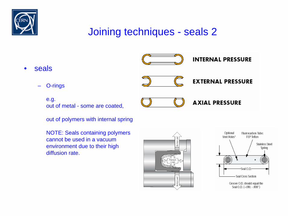
Joining techniques - seals 2
• seals
– O-rings
e.g.out of metal - some are coated,
out of polymers with internal spring
NOTE: Seals containing polymerscannot be used in a vacuum environment due to their highdiffusion rate.
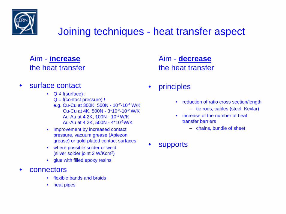
Joining techniques - heat transfer aspect
Aim - increasethe heat transfer
• surface contact• Q = f(surface) ;
Q = f(contact pressure) ! e.g. Cu-Cu at 300K, 500N - 10-2-10-1 W/K
Cu-Cu at 4K, 500N - 3*10-3-10-2 W/KAu-Au at 4,2K, 100N - 10-1 W/KAu-Au at 4,2K, 500N - 4*10-1W/K
• Improvement by increased contact pressure, vacuum grease (Apiezongrease) or gold-plated contact surfaces
• where possible solder or weld(silver solder joint 2 W/Kcm2)
• glue with filled epoxy resins
• connectors• flexible bands and braids• heat pipes
Aim - decreasethe heat transfer
• principles
• reduction of ratio cross section/length– tie rods, cables (steel, Kevlar)
• increase of the number of heattransfer barriers
– chains, bundle of sheet
• supports
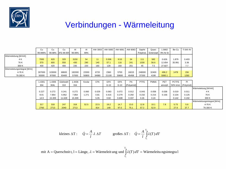
Verbindungen - Wärmeleitung
Cu Cu Cu Al Al AW 3003 AW 5083 AW 6061 AW 6063 Saphir Quarz 1.5662 Be-Cu Ti 6Al 4V99.999% 99.98% OFE-99.95% 99.99% 99% Polykrist. Einkristall 9% Ni St
Wärmeleitung [W/mK]4 K 7000 620 320 3150 54 11 0.506 9.53 34 111 582 0.626 1.879 0.40376 K 570 600 550 430 290 140 57.1 116 241 1030 56.6 12.654 35.991 3.36
300 K 400 420 400 235 220 160 128 160 201 45 7.5 27.827 7.7Wärmeleitungsintegral [W/m]
4-76 K 307000 103000 68600 182000 22000 6720 2360 5700 16015 248000 32400 496.2 1478 15676-300 K 93000 97000 93400 57000 50800 34980 21100 30600 45458 37200 4190 5060.1 1260
1.4301 1.4306 Edelstahl 1.4436 Kevlar CFK GFK GFK PA PTFE PMMA PET PCTFE PI304 304L 310 316 G-10 G-10 (Polyamid) amorph 50% krist. (Polyimid)
Wärmeleitung [W/mK]0.227 0.272 0.241 0.272 0.060 0.029 0.063 0.072 0.012 0.043 0.058 0.038 0.019 0.011 4 K8.01 7.854 5.952 7.854 1.271 0.81 0.415 0.279 0.292 0.232 0.215 0.156 0.104 0.125 76 K14.9 15.309 11.628 15.309 5.05 0.82 0.608 0.337 0.26 0.24 0.142 0.192 300 K
Wärmeleitungsintegral [W/m]317 318 247 318 52.5 22.5 19.2 14.7 13.0 12.8 10.1 7.8 5.73 5.6 4-76 K
2760 2713 2040 2713 814 148 97.0 75.1 57.2 52.9 27.9 37.7 76-300 K
∫
∫
====
=∆∆=∆
2
1
2
1
lngsintegraWärmeleitu)(und ung Wärmeleit Länge,l t,QuerschnitAmit
)( :T großes :T kleines
T
T
T
T
dTT
dTTlAQT
lAQ
λλ
λλ &&
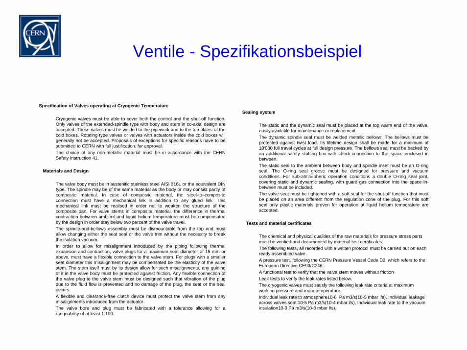
Ventile - Spezifikationsbeispiel
Specification of Valves operating at Cryogenic Temperature
Cryogenic valves must be able to cover both the control and the shut-off function. Only valves of the extended-spindle type with body and stem in co-axial design are accepted. These valves must be welded to the pipework and to the top plates of the cold boxes. Rotating type valves or valves with actuators inside the cold boxes will generally not be accepted. Proposals of exceptions for specific reasons have to be submitted to CERN with full justification, for approval.The choice of any non-metallic material must be in accordance with the CERN Safety Instruction 41.
Materials and Design
The valve body must be in austenitic stainless steel AISI 316L or the equivalent DIN type. The spindle may be of the same material as the body or may consist partly of composite material. In case of composite material, the steel-to–composite connection must have a mechanical link in addition to any glued link. This mechanical link must be realised in order not to weaken the structure of the composite part. For valve stems in composite material, the difference in thermal contraction between ambient and liquid helium temperature must be compensated by the design in order stay below two percent of the valve travel. The spindle-and-bellows assembly must be dismountable from the top and must allow changing either the seat seal or the valve trim without the necessity to break the isolation vacuum.In order to allow for misalignment introduced by the piping following thermal expansion and contraction, valve plugs for a maximum seat diameter of 15 mm or above, must have a flexible connection to the valve stem. For plugs with a smaller seat diameter this misalignment may be compensated be the elasticity of the valve stem. The stem itself must by its design allow for such misalignments, any guiding of it in the valve body must be protected against friction. Any flexible connection of the valve plug to the valve stem must be designed such that vibration of the plug due to the fluid flow is prevented and no damage of the plug, the seat or the seal occurs.A flexible and clearance-free clutch device must protect the valve stem from any misalignments introduced from the actuator.The valve bore and plug must be fabricated with a tolerance allowing for a rangeability of at least 1:100.
Sealing system
The static and the dynamic seal must be placed at the top warm end of the valve, easily available for maintenance or replacement.The dynamic spindle seal must be welded metallic bellows. The bellows must be protected against twist load. Its lifetime design shall be made for a minimum of 10'000 full travel cycles at full design pressure. The bellows seal must be backed by an additional safety stuffing box with check-connection to the space enclosed in between.The static seal to the ambient between body and spindle inset must be an O-ring seal. The O-ring seal groove must be designed for pressure and vacuum conditions. For sub-atmospheric operation conditions a double O-ring seal joint, covering static and dynamic sealing, with guard gas connection into the space in-between must be included.The valve seat must be tightened with a soft seal for the shut-off function that must be placed on an area different from the regulation cone of the plug. For this soft seal only plastic materials proven for operation at liquid helium temperature are accepted.
Tests and material certificates
The chemical and physical qualities of the raw materials for pressure stress parts must be verified and documented by material test certificates.The following tests, all recorded with a written protocol must be carried out on each ready assembled valve.A pressure test, following the CERN Pressure Vessel Code D2, which refers to the European Directive CE93/C246.A functional test to verify that the valve stem moves without frictionLeak tests to verify the leak rates listed below.The cryogenic valves must satisfy the following leak rate criteria at maximum working pressure and room temperature.Individual leak rate to atmosphere10-6 Pa m3/s(10-5 mbar l/s), Individual leakage across valves seat:10-5 Pa m3/s(10-4 mbar l/s), Individual leak rate to the vacuum insulation10-9 Pa m3/s(10-8 mbar l/s).
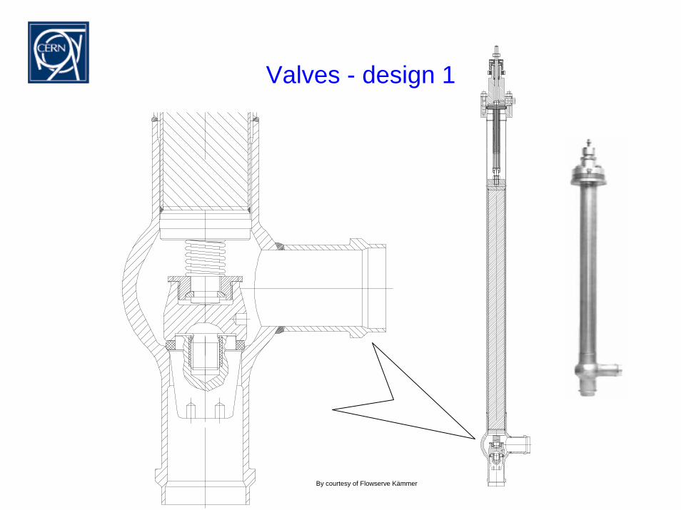
By courtesy of Flowserve Kämmer
Valves - design 1
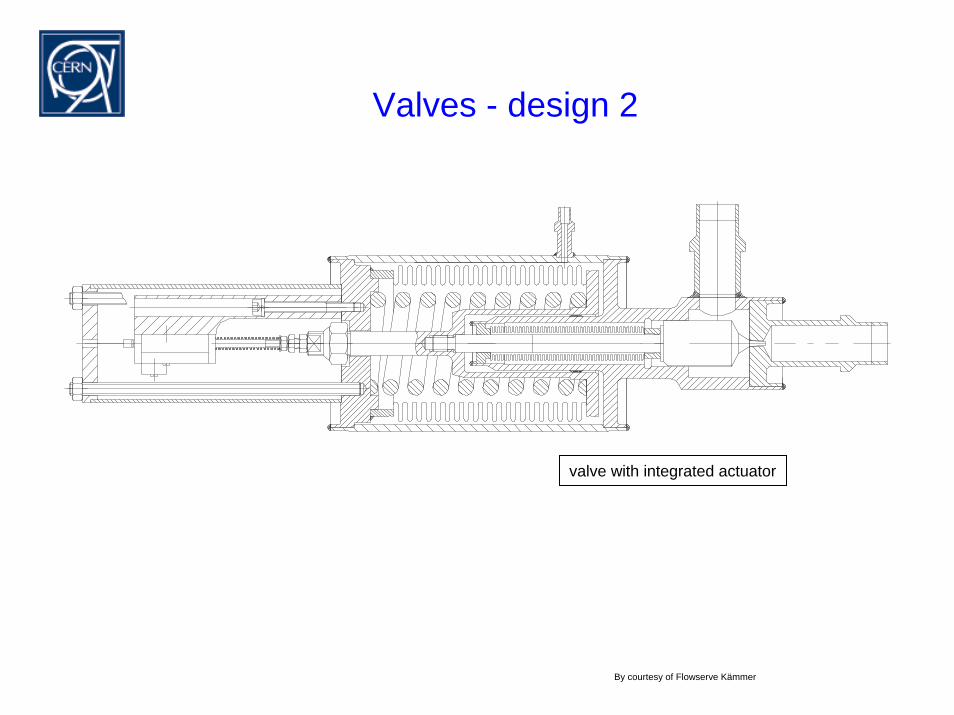
Valves - design 2
valve with integrated actuator
By courtesy of Flowserve Kämmer
Valves - design (DIN534)
GV
GV
V
Tp
mk
ppTmk
pmk
ρ
ρ
ρ
1
1
12
2
G1
2
1
12
3
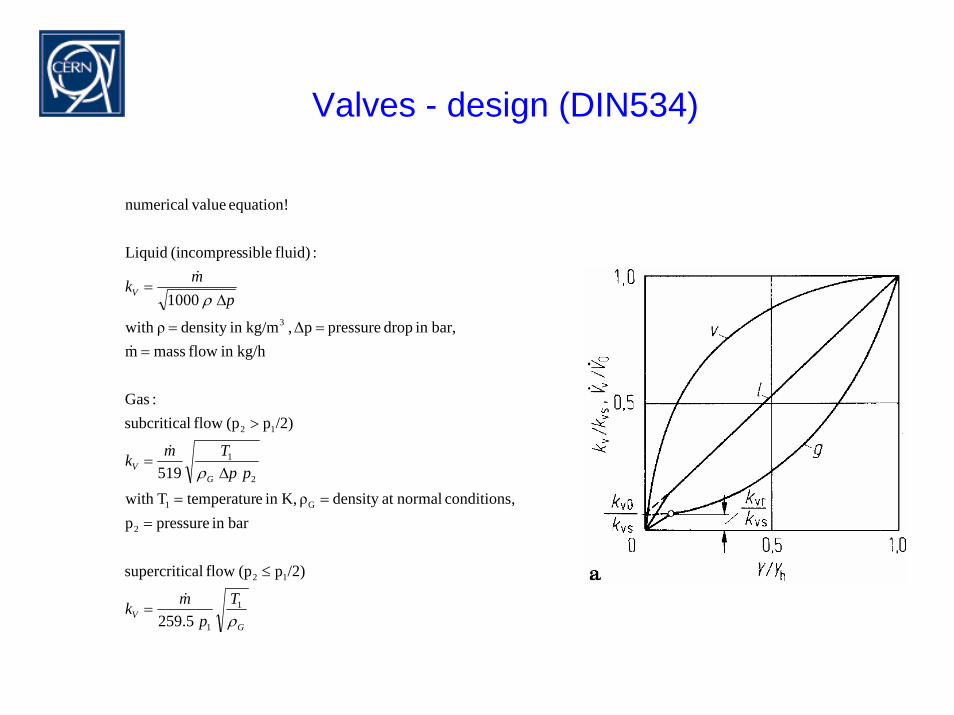
5.259
/2)p(p flow calsupercriti
barin pressurep ,conditions normalat density ρ K,in etemperaturTwith
519
/2)p(p flow lsubcritica:Gas
kg/hin flow massm bar,in drop pressure ∆p, kg/min density ρwith
1000
:fluid) sible(incompres Liquid
equation! valuenumerical
&
&
&
&
=
≤
===
∆=
>
===
∆=
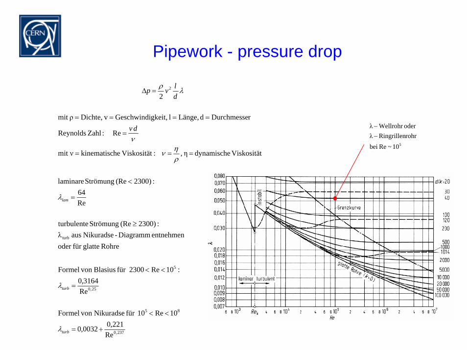
Pipework - pressure drop
237,0
85
25,0
5
turb
2
Re221,00032,0
10Re 10für Nikuradse von Formel
Re3164,0
:10Re 2300für Blasius von Formel
Rohre glattefür oder entnehmen Diagramm-Nikuradse aus λ
:2300)(Re Strömung turbulente
Re64
:2300)(Re Strömung laminare
Viskosität dynamische η , :Viskosität hekinematiscνmit
Re : ZahlReynolds
rDurchmessed Länge,l gkeit,Geschwindi vDichte,ρmit
2
+=
<<
=
<<
≥
=
<
===
=
====
=∆
turb
turb
lam
dv
dlvp
λ
λ
λ
ρην
ν
λρ
510~RebeirohrRingrillenλoderWellrohr λ
−−
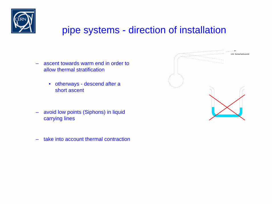
pipe systems - direction of installation
z.B. Sicherheitsventil
– ascent towards warm end in order to allow thermal stratification
• otherways - descend after a short ascent
– avoid low points (Siphons) in liquidcarrying lines
– take into account thermal contraction
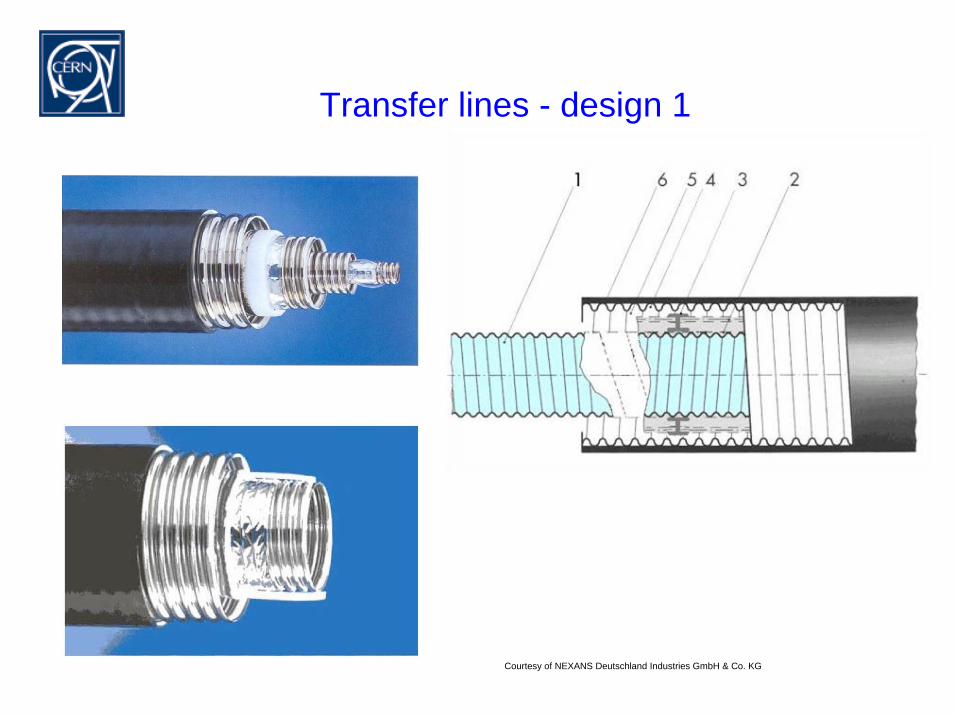
Transfer lines - design 1
Courtesy of NEXANS Deutschland Industries GmbH & Co. KG
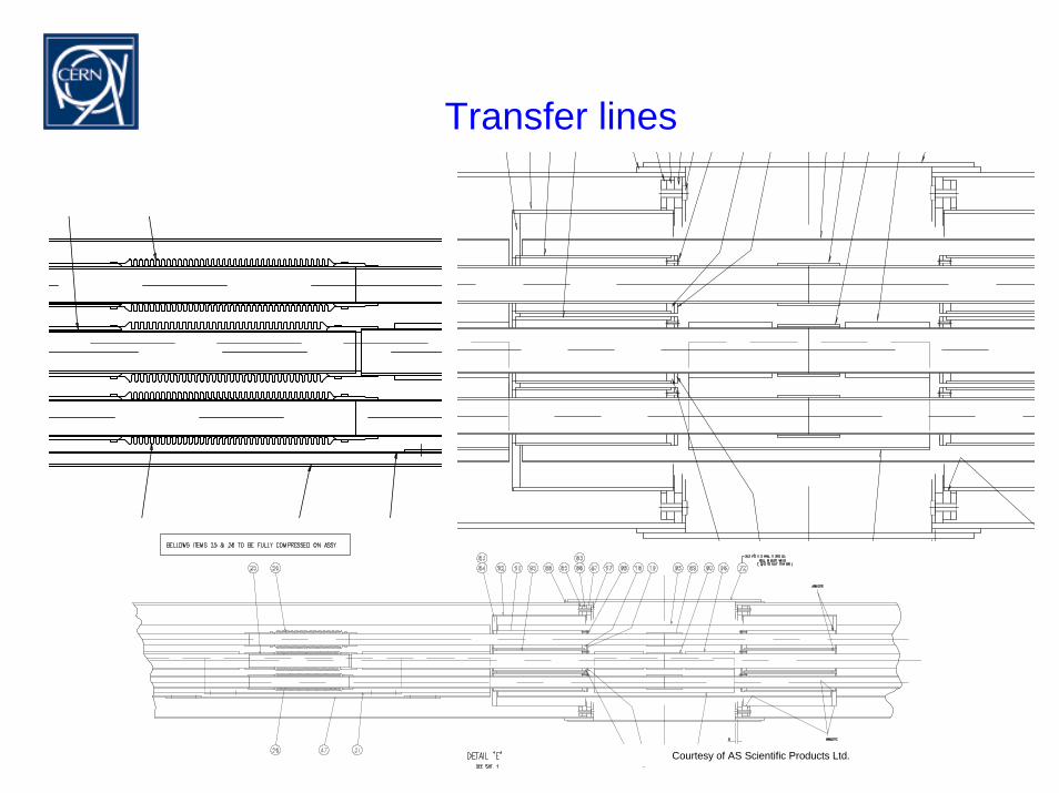
Transfer lines
Courtesy of AS Scientific Products Ltd.
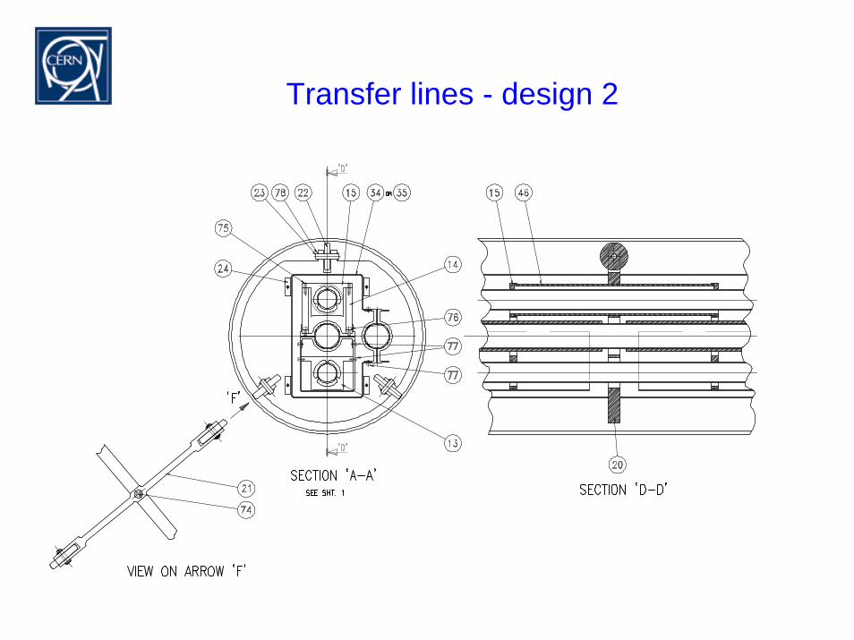
Transfer lines - design 2
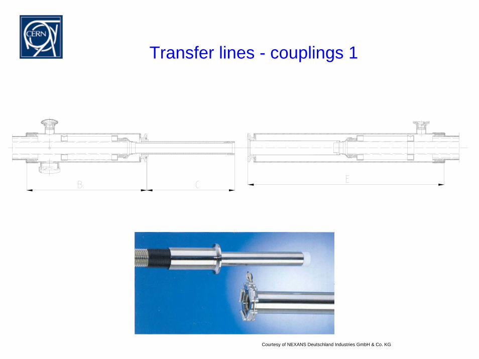
Transfer lines - couplings 1
Courtesy of NEXANS Deutschland Industries GmbH & Co. KG
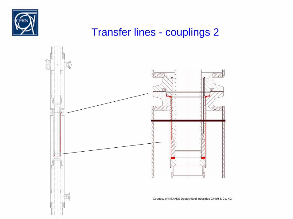
Transfer lines - couplings 2
Courtesy of NEXANS Deutschland Industries GmbH & Co. KG
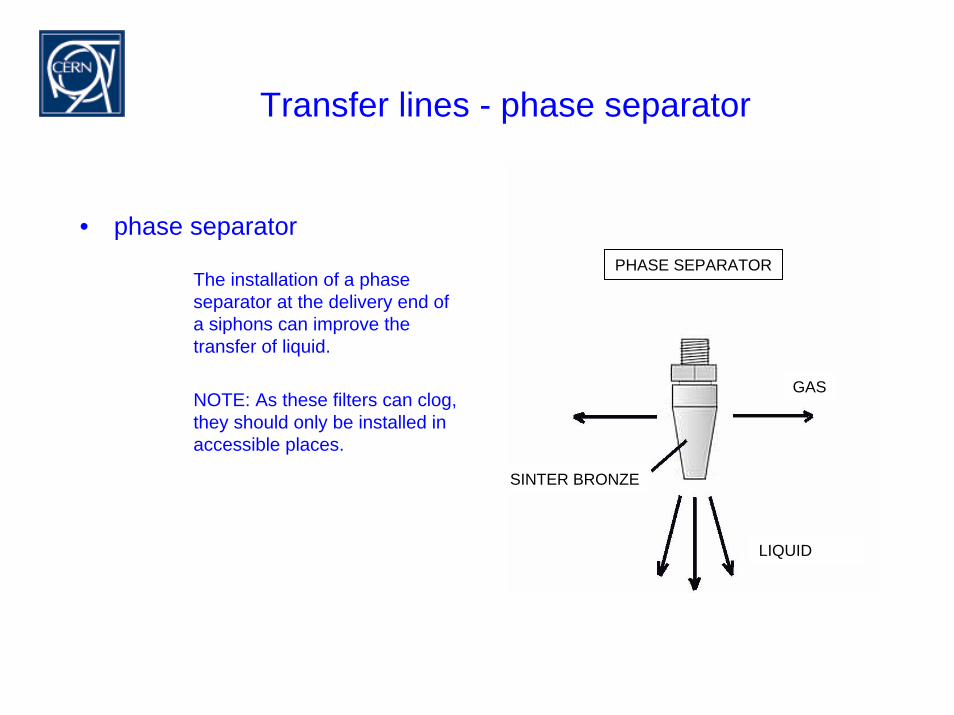
Transfer lines - phase separator
GAS
LIQUID
SINTER BRONZE
PHASE SEPARATOR
• phase separator
The installation of a phase separator at the delivery end ofa siphons can improve thetransfer of liquid.
NOTE: As these filters can clog, they should only be installed in accessible places.
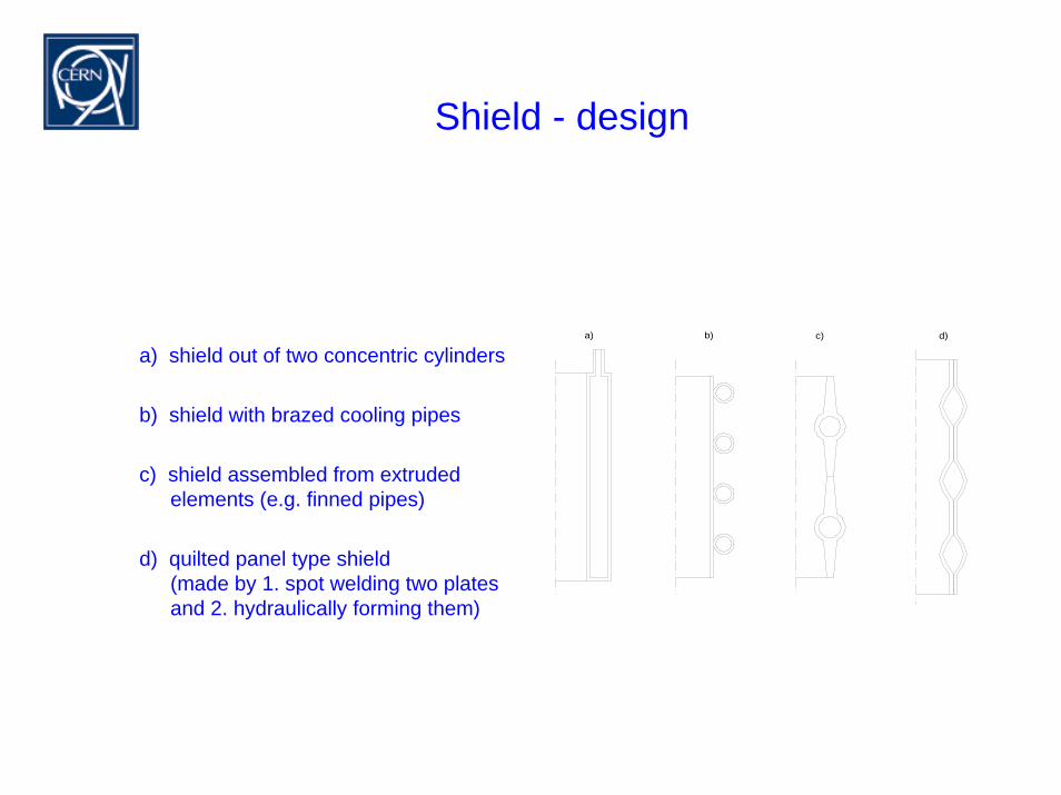
Shield - design
b) d)c)a)
a) shield out of two concentric cylinders
b) shield with brazed cooling pipes
c) shield assembled from extrudedelements (e.g. finned pipes)
d) quilted panel type shield(made by 1. spot welding two platesand 2. hydraulically forming them)
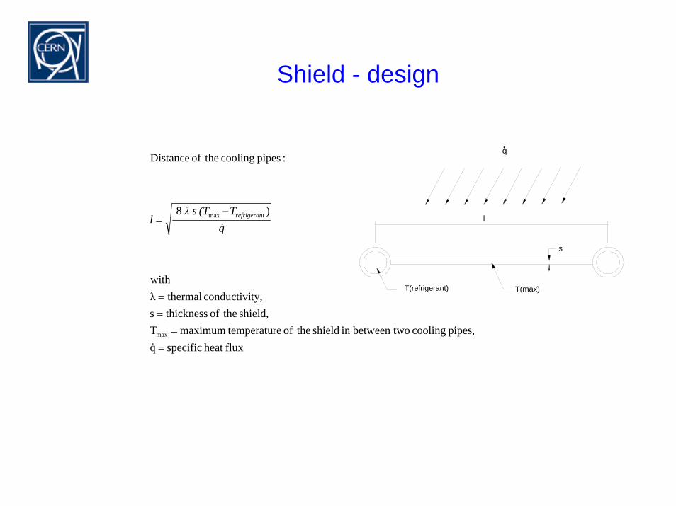
Shield - design
fluxheat specificqpipes, cooling obetween twin shield theof re temperatumaximum T
shield, theof thicknesss ty,conductivi thermalλ
with
)8
:pipes cooling theof Distance
max
max
==
==
−=
&
&qT(Tsλ
l trefrigeran l
T(max)T(Kühlleitung)
s
q
T(refrigerant)
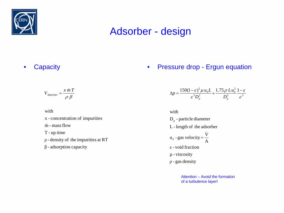
Adsorber - design
• Capacity • Pressure drop - Ergun equation
Attention – Avoid the formationof a turbulence layer!
density gas - ρviscosity-µ
fraction void- εAV velocity gas- u
adsorber theoflength - L
diameter particle - Dwith
175.1)1(150
0
p
32
20
230
2
&=
−+
−=∆
εερ
εµε
pp DuL
DLup
capacity adsorption - βRTat impurities theofdensity - ρ
timeup - Tflow mass - m
impurities ofion concentrat -x with
&
&
βρTmxVAdsorber =
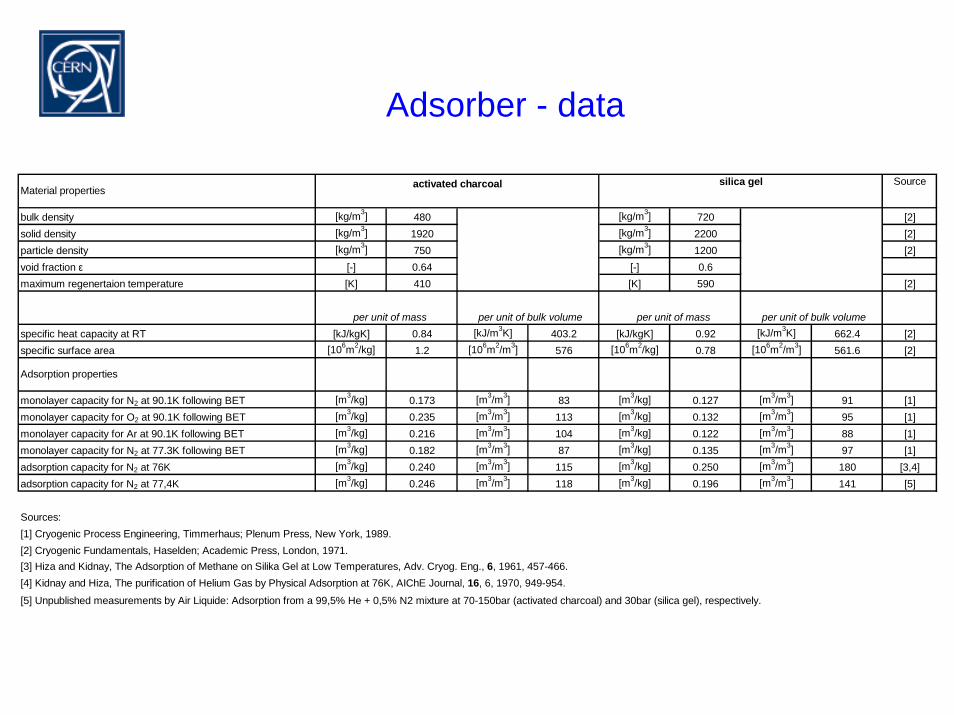
Adsorber - data
Source
bulk density [kg/m3] 480 [kg/m3] 720 [2]solid density [kg/m3] 1920 [kg/m3] 2200 [2]particle density [kg/m3] 750 [kg/m3] 1200 [2]void fraction ε [-] 0.64 [-] 0.6maximum regenertaion temperature [K] 410 [K] 590 [2]
specific heat capacity at RT [kJ/kgK] 0.84 [kJ/m3K] 403.2 [kJ/kgK] 0.92 [kJ/m3K] 662.4 [2]specific surface area [106m2/kg] 1.2 [106m2/m3] 576 [106m2/kg] 0.78 [106m2/m3] 561.6 [2]
monolayer capacity for N2 at 90.1K following BET [m3/kg] 0.173 [m3/m3] 83 [m3/kg] 0.127 [m3/m3] 91 [1]monolayer capacity for O2 at 90.1K following BET [m3/kg] 0.235 [m3/m3] 113 [m3/kg] 0.132 [m3/m3] 95 [1]monolayer capacity for Ar at 90.1K following BET [m3/kg] 0.216 [m3/m3] 104 [m3/kg] 0.122 [m3/m3] 88 [1]monolayer capacity for N2 at 77.3K following BET [m3/kg] 0.182 [m3/m3] 87 [m3/kg] 0.135 [m3/m3] 97 [1]adsorption capacity for N2 at 76K [m3/kg] 0.240 [m3/m3] 115 [m3/kg] 0.250 [m3/m3] 180 [3,4]adsorption capacity for N2 at 77,4K [m3/kg] 0.246 [m3/m3] 118 [m3/kg] 0.196 [m3/m3] 141 [5]
Sources:[1] Cryogenic Process Engineering, Timmerhaus; Plenum Press, New York, 1989.[2] Cryogenic Fundamentals, Haselden; Academic Press, London, 1971.[3] Hiza and Kidnay, The Adsorption of Methane on Silika Gel at Low Temperatures, Adv. Cryog. Eng., 6, 1961, 457-466.[4] Kidnay and Hiza, The purification of Helium Gas by Physical Adsorption at 76K, AIChE Journal, 16, 6, 1970, 949-954.
[5] Unpublished measurements by Air Liquide: Adsorption from a 99,5% He + 0,5% N2 mixture at 70-150bar (activated charcoal) and 30bar (silica gel), respectively.
Adsorption properties
Material properties activated charcoal silica gel
per unit of mass per unit of bulk volume per unit of mass per unit of bulk volume
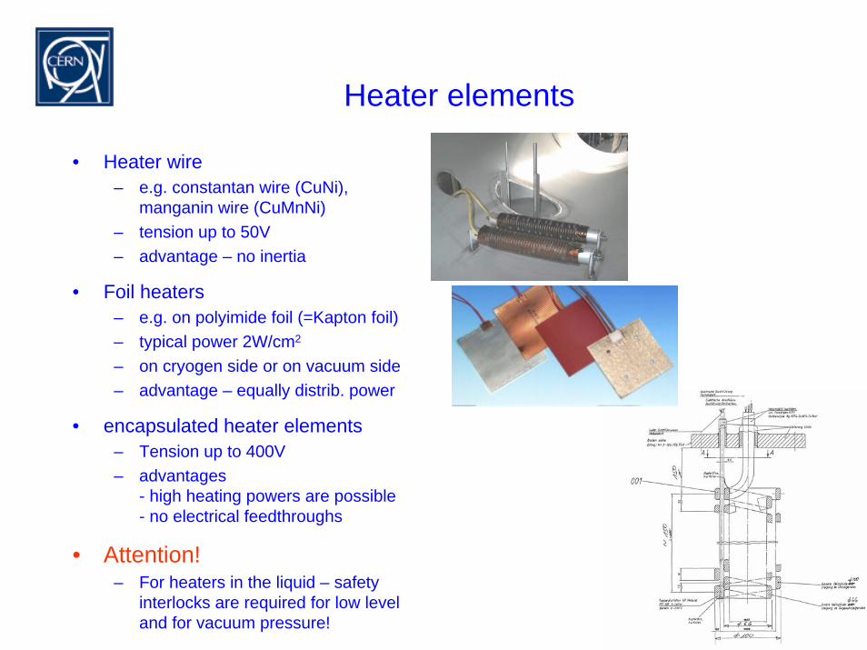
Heater elements
• Heater wire– e.g. constantan wire (CuNi),
manganin wire (CuMnNi) – tension up to 50V– advantage – no inertia
• Foil heaters– e.g. on polyimide foil (=Kapton foil)– typical power 2W/cm2
– on cryogen side or on vacuum side– advantage – equally distrib. power
• encapsulated heater elements– Tension up to 400V– advantages
- high heating powers are possible- no electrical feedthroughs
• Attention!– For heaters in the liquid – safety
interlocks are required for low leveland for vacuum pressure!
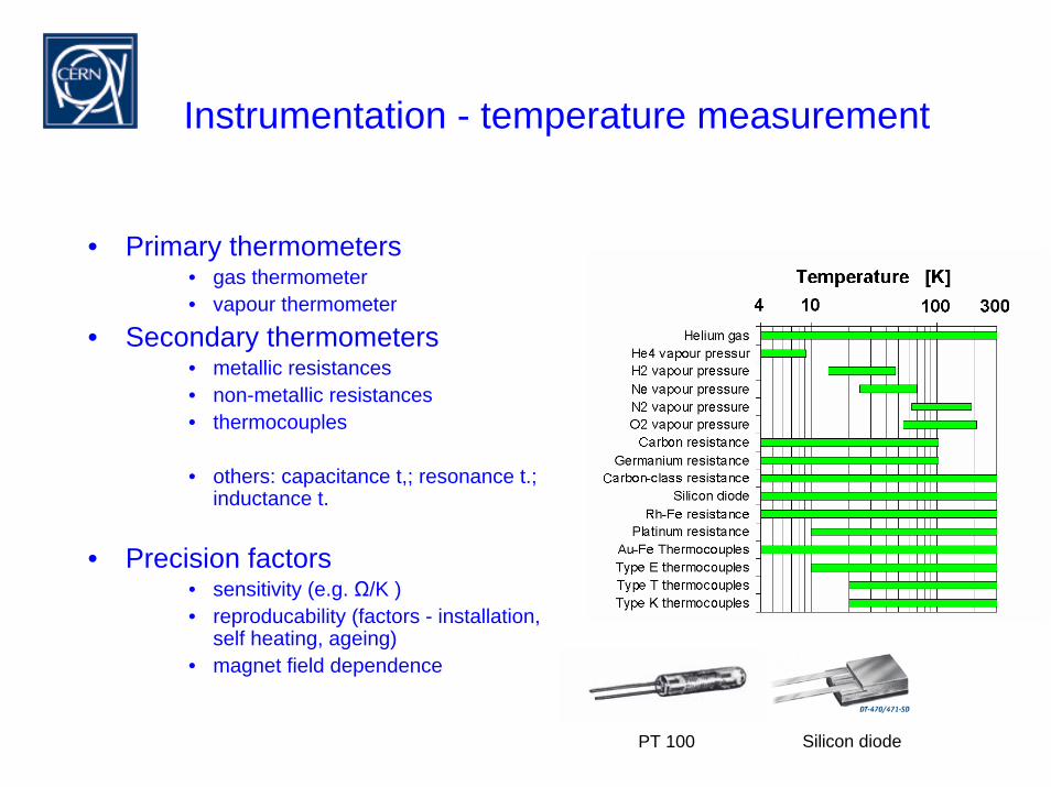
Instrumentation - temperature measurement
• Primary thermometers• gas thermometer• vapour thermometer
• Secondary thermometers• metallic resistances• non-metallic resistances• thermocouples
• others: capacitance t,; resonance t.;inductance t.
• Precision factors• sensitivity (e.g. Ω/K )• reproducability (factors - installation,
self heating, ageing)• magnet field dependence
Silicon diodePT 100
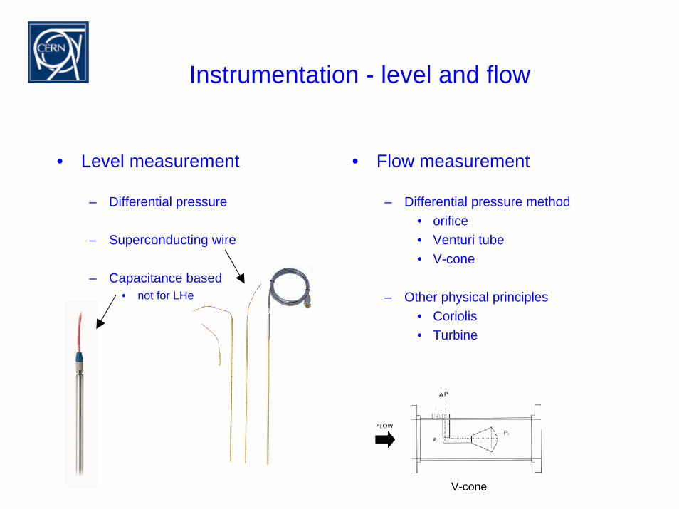
Instrumentation - level and flow
• Level measurement
– Differential pressure
– Superconducting wire
– Capacitance based• not for LHe
• Flow measurement
– Differential pressure method• orifice• Venturi tube• V-cone
– Other physical principles• Coriolis• Turbine
V-cone
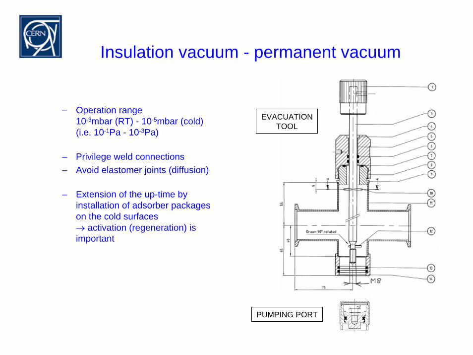
Insulation vacuum - permanent vacuum
– Operation range10-3mbar (RT) - 10-5mbar (cold)(i.e. 10-1Pa - 10-3Pa)
– Privilege weld connections– Avoid elastomer joints (diffusion)
– Extension of the up-time by installation of adsorber packages on the cold surfaces→ activation (regeneration) is important
EVACUATIONTOOL
PUMPING PORT
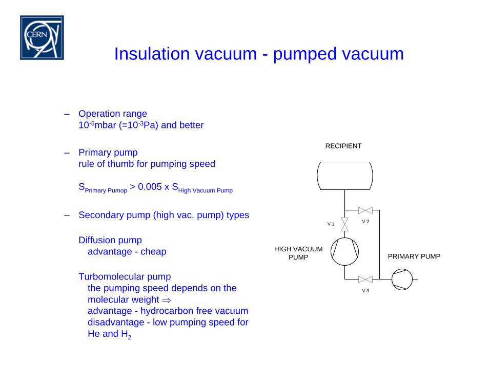
Insulation vacuum - pumped vacuum
– Operation range10-5mbar (=10-3Pa) and better
– Primary pumprule of thumb for pumping speed
SPrimary Pumop > 0.005 x SHigh Vacuum Pump
– Secondary pump (high vac. pump) types
Diffusion pumpadvantage - cheap
Turbomolecular pumpthe pumping speed depends on the molecular weight ⇒advantage - hydrocarbon free vacuumdisadvantage - low pumping speed for He and H2
Hochvakuum-pumpe Vorpumpe
V 1
Rezipient
V 2
V 3
PRIMARY PUMPHIGH VACUUM
PUMP
RECIPIENT
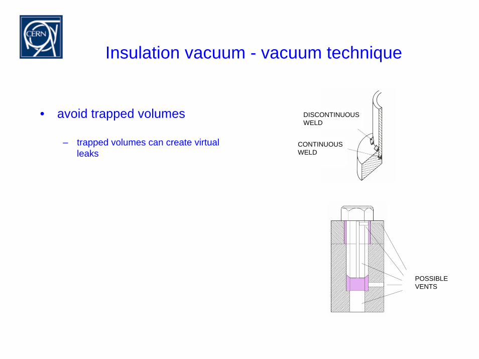
Insulation vacuum - vacuum technique
• avoid trapped volumes
– trapped volumes can create virtual leaks
DISCONTINUOUSWELD
CONTINUOUSWELD
möglicheEntlüftungen
POSSIBLE VENTS

Day 3
Introduction to Cryogenic Engineering
MONDAY From History to Modern Refrigeration Cycles (G. Perinić)
TUESDAY Standard Components, Cryogenic Design (G. Perinić)
WEDNESDAY Heat Transfer and Insulation (G. Vandoni)
THURSDAY Safety, Information Resources (G. Perinić)
FRIDAY Applications of Cryogenic Engineering (T. Niinikoski)
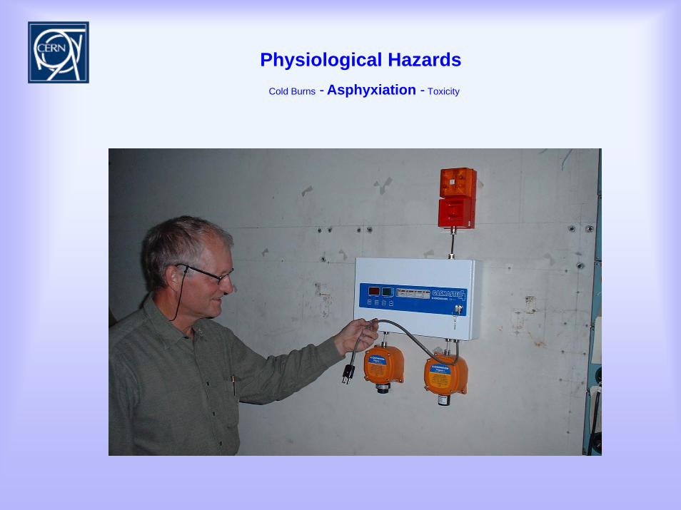
Physiological hazards
Sources of accidents and failures
Information resources

Safety
Physiological HazardsCold Burns - Asphyxiation - Toxicity
( )• Toxicity– CO, F2, O3
• Cold Burns– Contact with cryogenic liquids or cold surfaces
• Asphyxiation– Reduction of oxygen content
Physiological HazardsCold Burns - Asphyxiation - Toxicity
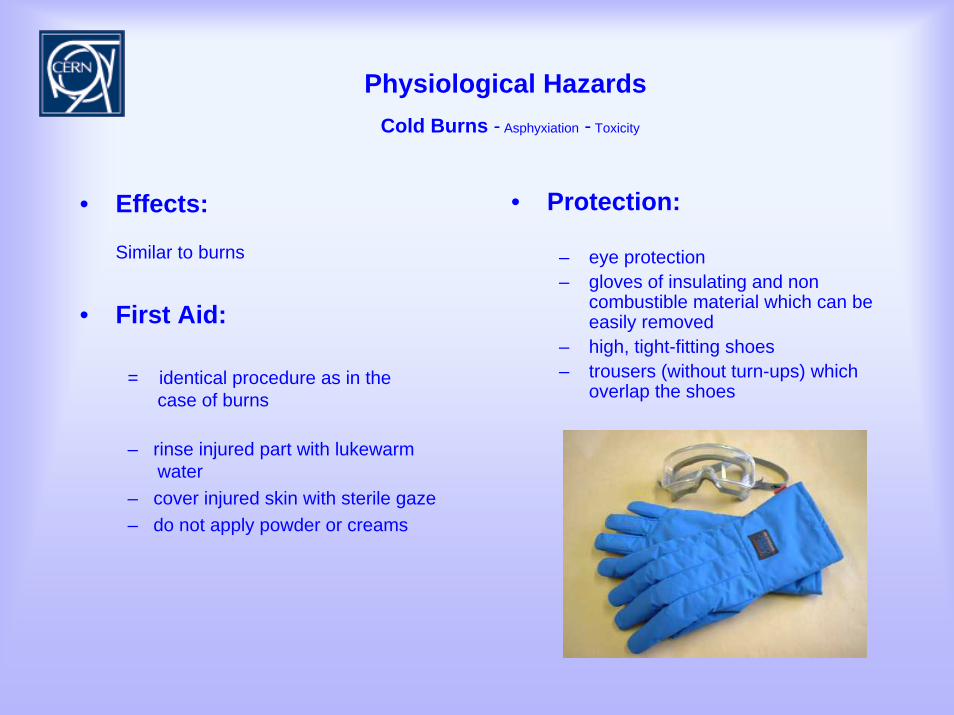
• Effects:
Similar to burns
• First Aid:
= identical procedure as in the case of burns
– rinse injured part with lukewarm water
– cover injured skin with sterile gaze– do not apply powder or creams
• Protection:
– eye protection– gloves of insulating and non
combustible material which can be easily removed
– high, tight-fitting shoes – trousers (without turn-ups) which
overlap the shoes
Physiological HazardsCold Burns - Asphyxiation - Toxicity
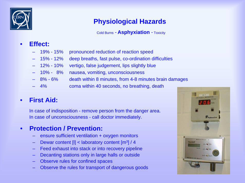
• Effect:– 19% - 15% pronounced reduction of reaction speed – 15% - 12% deep breaths, fast pulse, co-ordination difficulties – 12% - 10% vertigo, false judgement, lips slightly blue – 10% - 8% nausea, vomiting, unconsciousness – 8% - 6% death within 8 minutes, from 4-8 minutes brain damages – 4% coma within 40 seconds, no breathing, death
• First Aid:In case of indisposition - remove person from the danger area.In case of unconsciousness - call doctor immediately.
• Protection / Prevention:– ensure sufficient ventilation + oxygen monitors– Dewar content [l] < laboratory content [m3] / 4– Feed exhaust into stack or into recovery pipeline – Decanting stations only in large halls or outside– Observe rules for confined spaces– Observe the rules for transport of dangerous goods
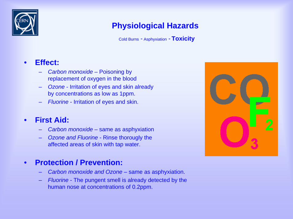
Physiological HazardsCold Burns - Asphyxiation - Toxicity
Physiological HazardsCold Burns - Asphyxiation - Toxicity
• Effect:– Carbon monoxide – Poisoning by
replacement of oxygen in the blood– Ozone - Irritation of eyes and skin already
by concentrations as low as 1ppm.– Fluorine - Irritation of eyes and skin.
• First Aid:– Carbon monoxide – same as asphyxiation– Ozone and Fluorine - Rinse thorougly the
affected areas of skin with tap water.
• Protection / Prevention:– Carbon monoxide and Ozone – same as asphyxiation.– Fluorine - The pungent smell is already detected by the
human nose at concentrations of 0.2ppm.
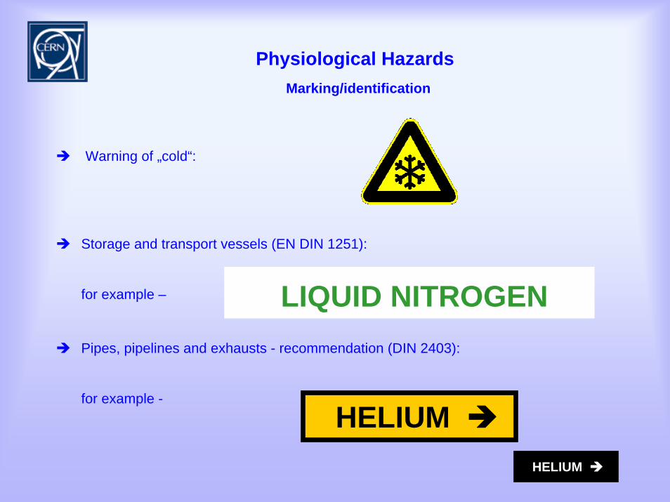
Physiological HazardsMarking/identification
Warning of „cold“:
Storage and transport vessels (EN DIN 1251):
for example –
Pipes, pipelines and exhausts - recommendation (DIN 2403):
for example -
LIQUID NITROGEN
HELIUM HELIUM
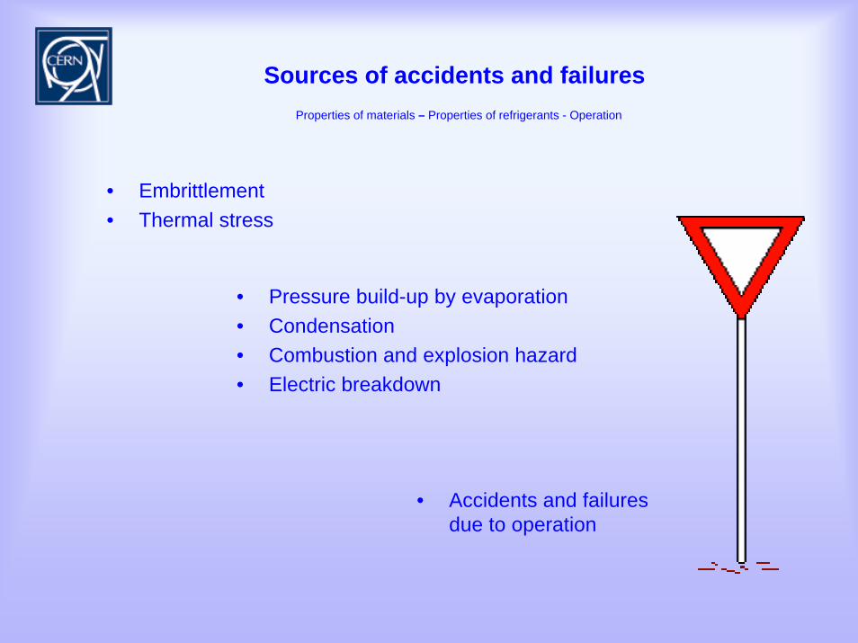
Sources of accidents and failuresProperties of materials – Properties of refrigerants - Operation
• Accidents and failures due to operation
• Embrittlement• Thermal stress
• Pressure build-up by evaporation• Condensation• Combustion and explosion hazard• Electric breakdown
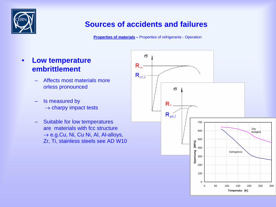
Sources of accidents and failuresProperties of materials – Properties of refrigerants - Operation
– Affects most materials more orless pronounced
– Is measured by → charpy impact tests
– Suitable for low temperatures are materials with fcc structure → e.g.Cu, Ni, Cu Ni, Al, Al-alloys, Zr, Ti, stainless steels see AD W10
• Low temperature embrittlement
0
100
200
300
400
500
600
700
0 50 100 150 200 250 300
Temperatur [K]Sp
annu
ng
[MPa
]
Dehngrenze
Zug-festigkeit
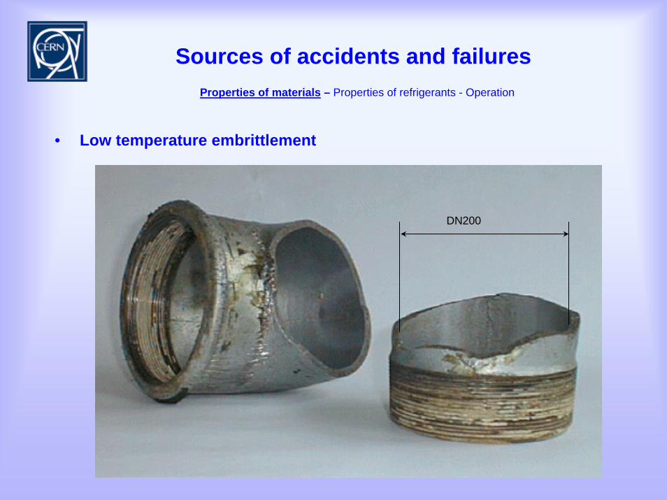
Sources of accidents and failuresProperties of materials – Properties of refrigerants - Operation
• Low temperature embrittlement
DN200
Sources of accidents and failuresProperties of materials – Properties of refrigerants - Operation
• Hydrogen embrittlement
– Several mechanisms exist, can originate from material production or from operation
– At risk are:• Metals with bcc-structure (e.g. ferritic steels),• High tensile steels used in the range 200-300K,• Materials under loads close to their limit of elasticity
– Means of protection:• linings or coatings with other metals,• over dimensioning
Sources of accidents and failuresProperties of materials – Properties of refrigerants - Operation
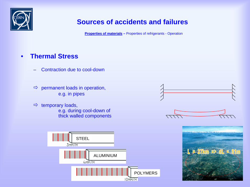
• Thermal Stress
– Contraction due to cool-down
permanent loads in operation, e.g. in pipes
temporary loads, e.g. during cool-down of thick walled components
STEEL
ALUMINIUM
POLYMERS
Sources of accidents and failuresProperties of materials – Properties of refrigerants - Operation
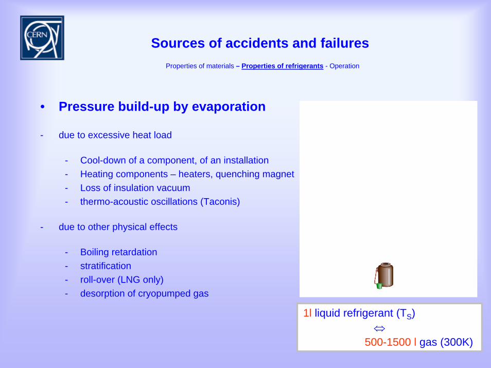
• Pressure build-up by evaporation
- due to excessive heat load
- Cool-down of a component, of an installation- Heating components – heaters, quenching magnet- Loss of insulation vacuum- thermo-acoustic oscillations (Taconis)
- due to other physical effects
- Boiling retardation- stratification- roll-over (LNG only)- desorption of cryopumped gas
1l liquid refrigerant (TS)⇔
500-1500 l gas (300K)
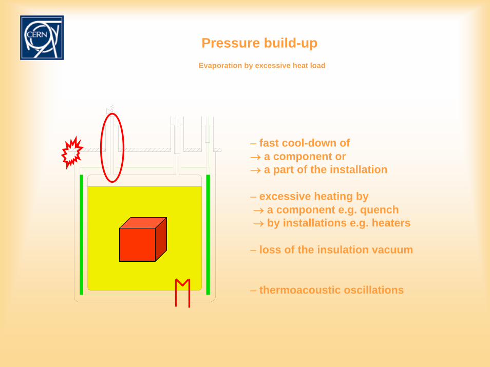
Pressure build-upEvaporation by excessive heat load
– fast cool-down of → a component or → a part of the installation
– excessive heating by→ a component e.g. quench→ by installations e.g. heaters
– loss of the insulation vacuum
– thermoacoustic oscillations
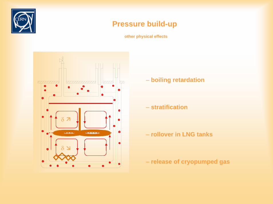
Pressure build-upother physical effects
– boiling retardation
– stratification
– rollover in LNG tanks
– release of cryopumped gas
δ
δ
Sources of accidents and failuresProperties of materials – Properties of refrigerants - Operation
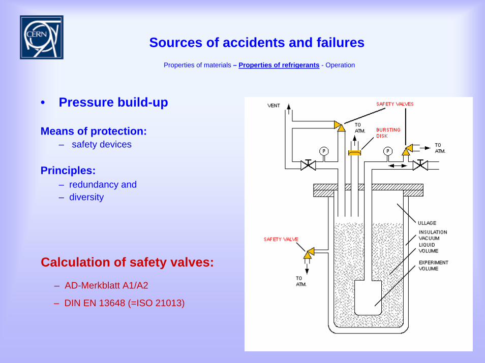
• Pressure build-up
Means of protection:– safety devices
Principles:– redundancy and – diversity
Calculation of safety valves:– AD-Merkblatt A1/A2
– DIN EN 13648 (=ISO 21013)
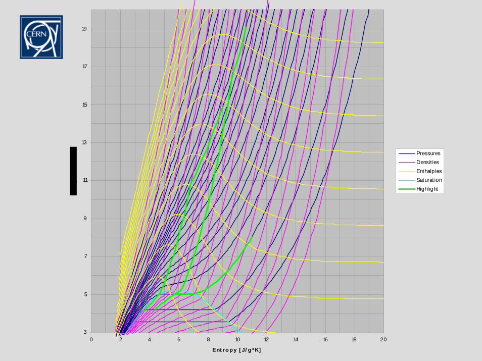
3
5
7
9
11
13
15
17
19
0 2 4 6 8 10 12 14 16 18 20
Ent ro p y [ J/ g *K]
PressuresDensit iesEnthalpiesSaturat ionHighlight
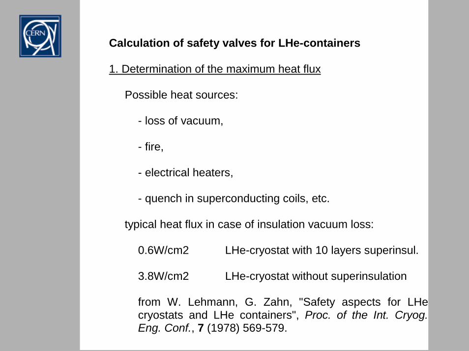
Calculation of safety valves for LHe-containers
1. Determination of the maximum heat flux
Possible heat sources:
- loss of vacuum, - fire, - electrical heaters, - quench in superconducting coils, etc.
typical heat flux in case of insulation vacuum loss:
0.6W/cm2 LHe-cryostat with 10 layers superinsul. 3.8W/cm2 LHe-cryostat without superinsulation
from W. Lehmann, G. Zahn, "Safety aspects for LHecryostats and LHe containers", Proc. of the Int. Cryog. Eng. Conf., 7 (1978) 569-579.
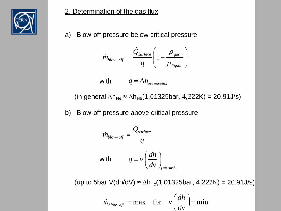
2. Determination of the gas flux
a) Blow-off pressure below critical pressure
with
(in general ∆hHe ≈ ∆hHe(1,01325bar, 4,222K) = 20.91J/s)
b) Blow-off pressure above critical pressure
with
(up to 5bar V(dh/dV) ≈ ∆hHe(1,01325bar, 4,222K) = 20.91J/s)
⎟⎟⎠
⎞⎜⎜⎝
⎛−=−
liquid
gassurfaceoffblow q
Qm
ρρ
1&
&
nevaporatiohq ∆=
.constpdvdhvq
=
⎟⎠⎞
⎜⎝⎛=
m surfaceoffblow
&& =−
minformax =⎟⎠⎞
⎜⎝⎛=− dv
dhvm offblow&
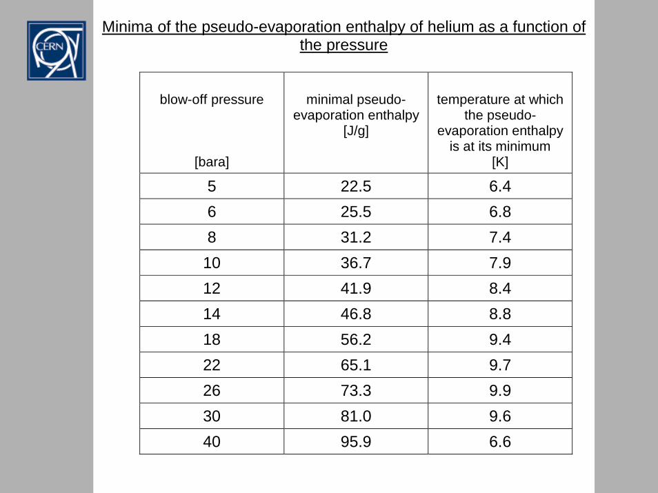
Minima of the pseudo-evaporation enthalpy of helium as a function of
the pressure
blow-off pressure
[bara]
minimal pseudo-
evaporation enthalpy[J/g]
temperature at which
the pseudo-evaporation enthalpy
is at its minimum [K]
5 22.5 6.4 6 25.5 6.8 8 31.2 7.4
10 36.7 7.9 12 41.9 8.4 14 46.8 8.8 18 56.2 9.4 22 65.1 9.7 26 73.3 9.9 30 81.0 9.6 40 95.9 6.6
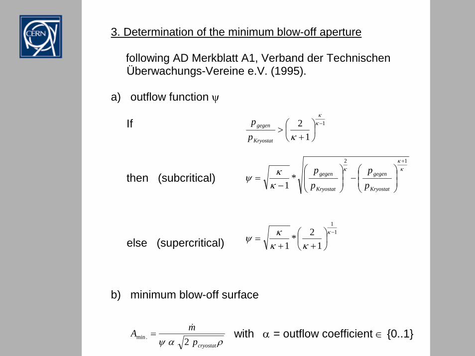
3. Determination of the minimum blow-off aperture
following AD Merkblatt A1, Verband der Technischen Überwachungs-Vereine e.V. (1995).
a) outflow function ψ
If
then (subcritical) else (supercritical)
b) minimum blow-off surface
with α = outflow coefficient ∈ 0..1
κκ
κ
κκψ
12
*1
+
⎟⎟⎠
⎞⎜⎜⎝
⎛−⎟
⎟⎠
⎞⎜⎜⎝
⎛
−=
Kryostat
gegen
Kryostat
gegen
pp
pp
1
12 −
⎟⎠⎞
⎜⎝⎛
+>
κκ
κKryostat
gegen
pp
11
12*
1−
⎟⎠⎞
⎜⎝⎛
++=
κ
κκκψ
ραψ cryostatpmA
2.min&
=
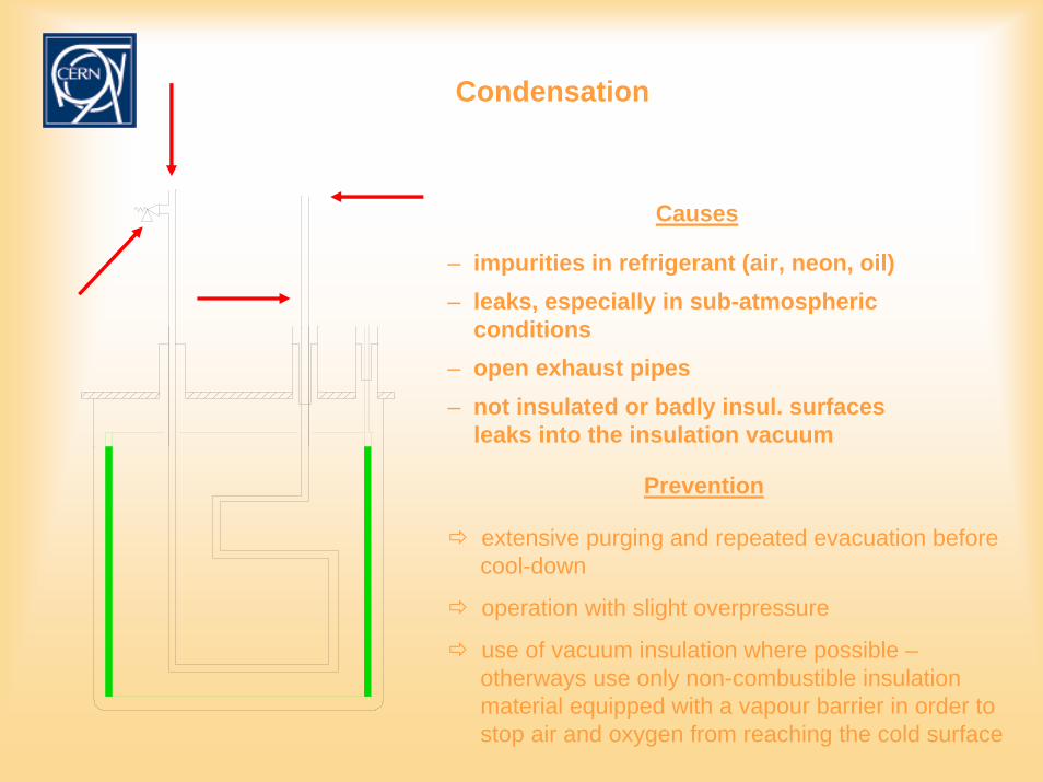
Condensation
– leaks, especially in sub-atmosphericconditions
– open exhaust pipes
extensive purging and repeated evacuation beforecool-down
operation with slight overpressure
– impurities in refrigerant (air, neon, oil)
Causes
– not insulated or badly insul. surfacesleaks into the insulation vacuum
Prevention
use of vacuum insulation where possible –otherways use only non-combustible insulationmaterial equipped with a vapour barrier in order tostop air and oxygen from reaching the cold surface
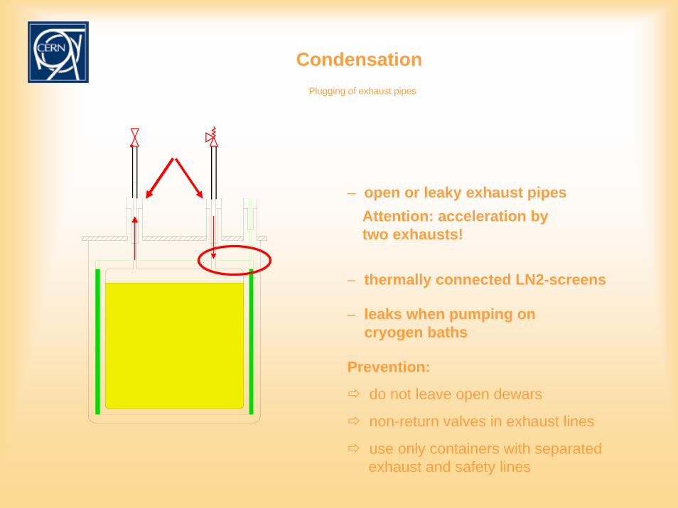
CondensationPlugging of exhaust pipes
– open or leaky exhaust pipesAttention: acceleration bytwo exhausts!
– thermally connected LN2-screens
– leaks when pumping on cryogen baths
Prevention:
do not leave open dewars
non-return valves in exhaust lines
use only containers with separatedexhaust and safety lines
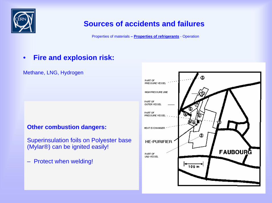
Sources of accidents and failuresProperties of materials – Properties of refrigerants - Operation
• Fire and explosion risk:
Methane, LNG, Hydrogen
Oxygen:
– accelerates combustion processes– reduces the ignition temperature
Hazardous are:– unsuitable materials– impurities, e.g. residues from
production and processing– penetration of porous materials by
gaseous and liquid oxygen
Ozone:
Oxygen can be transformed into Ozone by neutron irradiation!e.g. O2-impurities in a liquid nitrogen cooling circuit.Discomposes explosion like if triggered by the smallest excitement.
Other combustion dangers:
Superinsulation foils on Polyester base(Mylar®) can be ignited easily!
– Protect when welding!
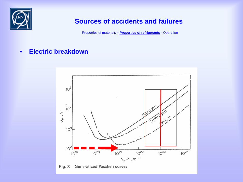
Sources of accidents and failuresProperties of materials – Properties of refrigerants - Operation
• Electric breakdown
Sources of accidents and failuresProperties of materials – Properties of refrigerants - Operation
• Plant operation
– operator errors– usage of unsuitable equipment– operating system errors– malfunctioning or failures of components– failure of safety equipment– Transport accidents – etc.
Preventive measures:
– Safety analysis and safety management

Information
Sources
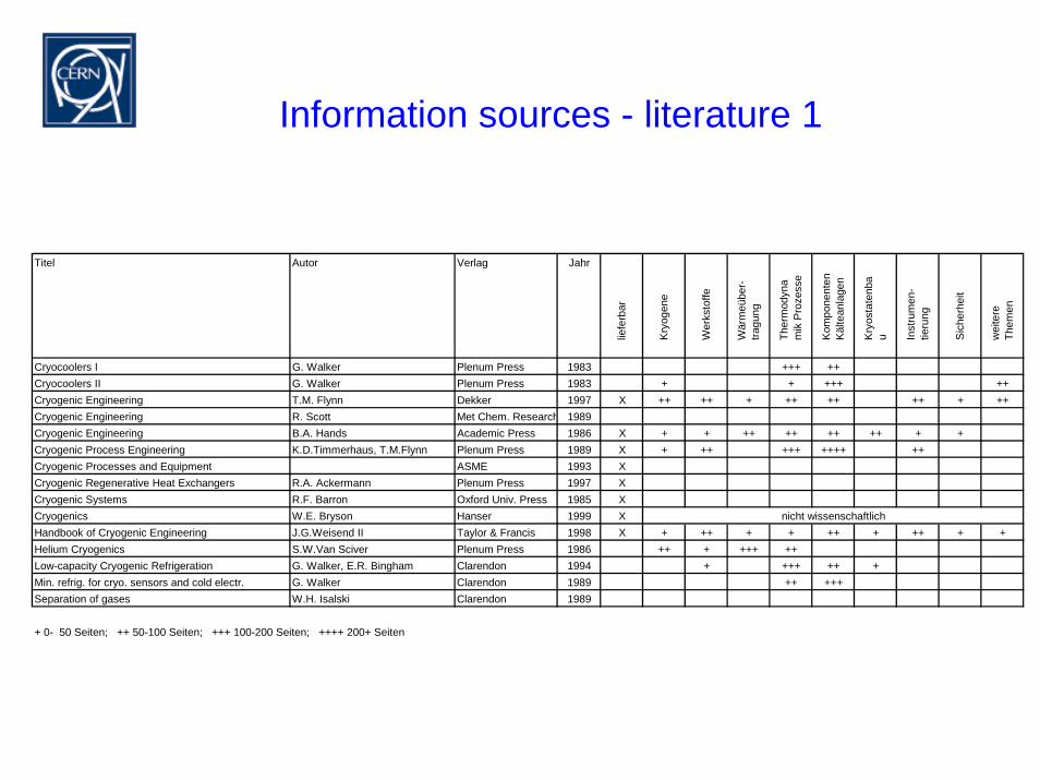
Information sources - literature 1
Titel Autor Verlag Jahr
liefe
rbar
Kry
ogen
e
Wer
ksto
ffe
Wär
meü
ber-
tragu
ng
Ther
mod
yna
mik
Pro
zess
e
Kom
pone
nten
K
älte
anla
gen
Kry
osta
tenb
au In
stru
men
-tie
rung
Sic
herh
eit
wei
tere
Th
emen
Cryocoolers I G. Walker Plenum Press 1983 +++ ++Cryocoolers II G. Walker Plenum Press 1983 + + +++ ++Cryogenic Engineering T.M. Flynn Dekker 1997 X ++ ++ + ++ ++ ++ + ++Cryogenic Engineering R. Scott Met Chem. Research 1989Cryogenic Engineering B.A. Hands Academic Press 1986 X + + ++ ++ ++ ++ + +Cryogenic Process Engineering K.D.Timmerhaus, T.M.Flynn Plenum Press 1989 X + ++ +++ ++++ ++Cryogenic Processes and Equipment ASME 1993 XCryogenic Regenerative Heat Exchangers R.A. Ackermann Plenum Press 1997 XCryogenic Systems R.F. Barron Oxford Univ. Press 1985 XCryogenics W.E. Bryson Hanser 1999 X nicht wissenschaftlichHandbook of Cryogenic Engineering J.G.Weisend II Taylor & Francis 1998 X + ++ + + ++ + ++ + +Helium Cryogenics S.W.Van Sciver Plenum Press 1986 ++ + +++ ++Low-capacity Cryogenic Refrigeration G. Walker, E.R. Bingham Clarendon 1994 + +++ ++ +Min. refrig. for cryo. sensors and cold electr. G. Walker Clarendon 1989 ++ +++Separation of gases W.H. Isalski Clarendon 1989
+ 0- 50 Seiten; ++ 50-100 Seiten; +++ 100-200 Seiten; ++++ 200+ Seiten
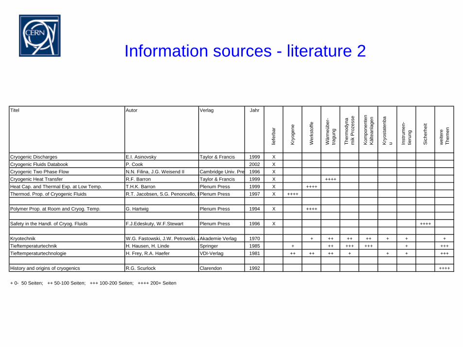
Information sources - literature 2
Titel Autor Verlag Jahr
liefe
rbar
Kryo
gene
Wer
ksto
ffe
Wär
meü
ber-
tragu
ng
Ther
mod
yna
mik
Pro
zess
e
Kom
pone
nten
K
älte
anla
gen
Kryo
stat
enba
u Inst
rum
en-
tieru
ng
Sic
herh
eit
wei
tere
Th
emen
Cryogenic Discharges E.I. Asinovsky Taylor & Francis 1999 XCryogenic Fluids Databook P. Cook 2002 XCryogenic Two Phase Flow N.N. Filina, J.G. Weisend II Cambridge Univ. Pre 1996 XCryogenic Heat Transfer R.F. Barron Taylor & Francis 1999 X ++++Heat Cap. and Thermal Exp. at Low Temp. T.H.K. Barron Plenum Press 1999 X ++++Thermod. Prop. of Cryogenic Fluids R.T. Jacobsen, S.G. Penoncello, EPlenum Press 1997 X ++++
Polymer Prop. at Room and Cryog. Temp. G. Hartwig Plenum Press 1994 X ++++
Safety in the Handl. of Cryog. Fluids F.J.Edeskuty, W.F.Stewart Plenum Press 1996 X ++++
Kryotechnik W.G. Fastowski, J.W. Petrowski, AAkademie Verlag 1970 + ++ ++ ++ + + +Tieftemperaturtechnik H. Hausen, H. Linde Springer 1985 + ++ +++ +++ + +++Tieftemperaturtechnologie H. Frey, R.A. Haefer VDI-Verlag 1981 ++ ++ ++ + + + +++
History and origins of cryogenics R.G. Scurlock Clarendon 1992 ++++
+ 0- 50 Seiten; ++ 50-100 Seiten; +++ 100-200 Seiten; ++++ 200+ Seiten
Information sources - journals/conferences
• Journals
– Cryogenics http://www.elsevier.nl/locate/cryogenics
• Conferences
– Listing http://cern.ch/Goran.Perinic/conf.htm
Information sources - data bases/formulas
• free information sources
– UIDAHO Center for Applied Thermodynamic Studies -cryogen property program http://www.webpages.uidaho.edu/~cats/software.htm
– NIST Cryogenic Technologies Group -material property equations http://cryogenics.nist.gov/NewFiles/material_properties.html
– ITS-90 -vapour pressure - temp. equation for helium http://www.its-90.com/its-90p3.html
• commercial information sources
– NIST - Thermodynamic and Transport Properties of Pure Fluids Database http://www.nist.gov/srd/nist12.htm
– CRYODATA -cryogen and material database http://www.htess.com/software.htm/
– Cryogenic Information Center -cryogen and material database and bibliography http://www.cryoinfo.org/

End

Extras
The cryogenists toolbox
• Internal Energy and Enthalpy• Energy conservation• Entropy Exergy• Diagrams TS, • Cycles• Efficiency
Energy conservation
• Bernoulli• static system
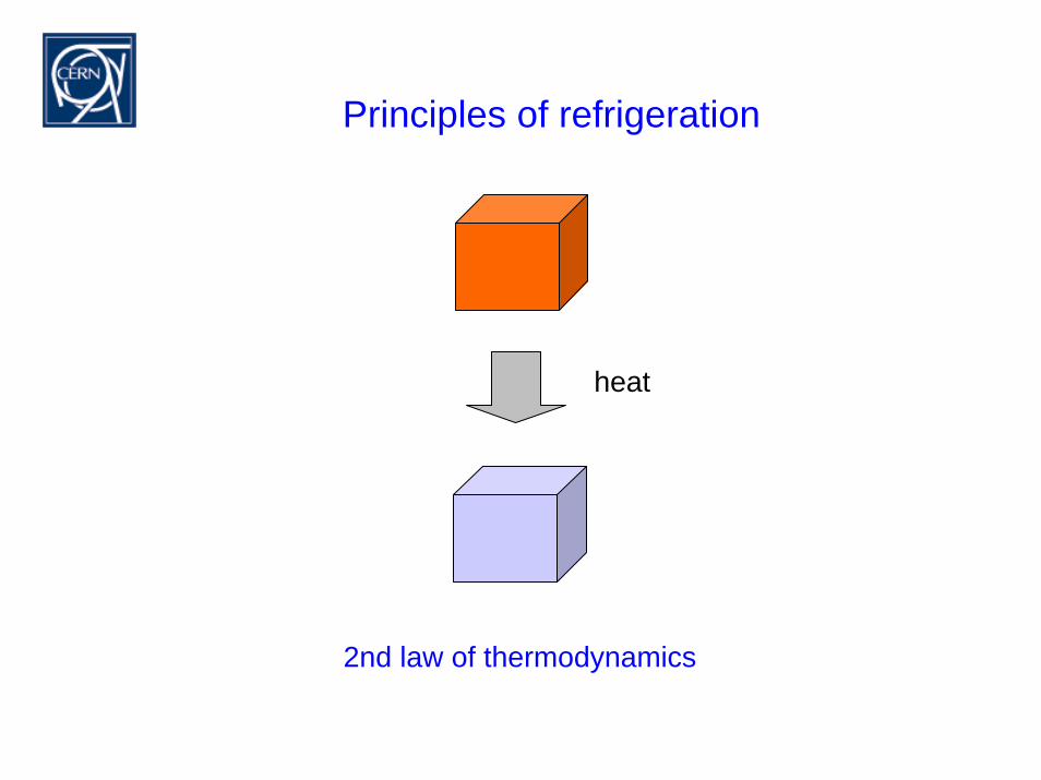
Principles of refrigeration
heat
2nd law of thermodynamics
Entropy
• dQ/T = S = const
• state variables p,T,V, U,H,S
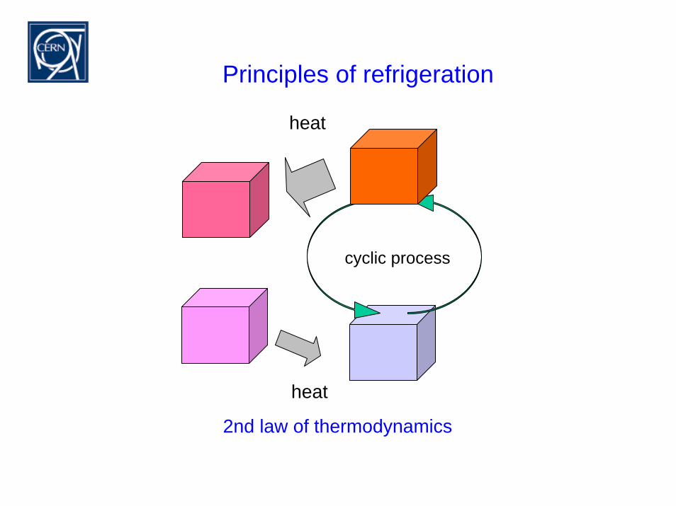
Principles of refrigeration
heat
2nd law of thermodynamics
cyclic process
heat
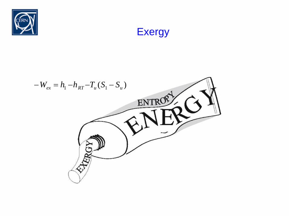
Exergy
)( 11 uuRTex SSThhW −−−=−
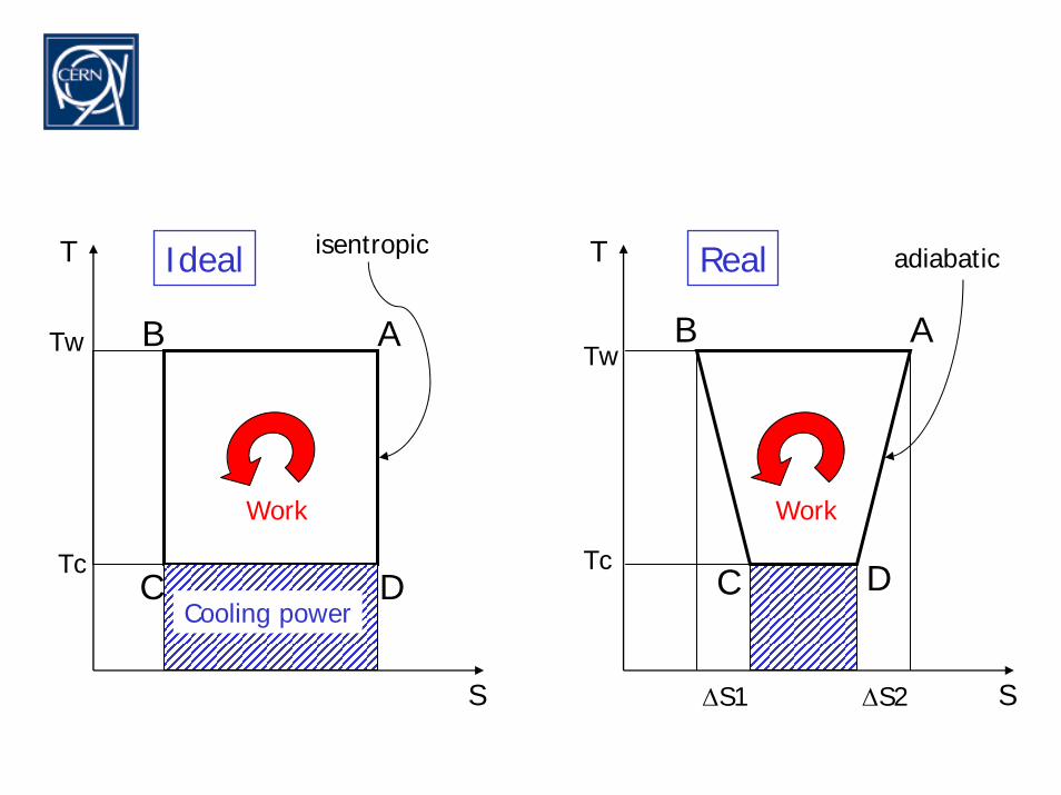
Tw
Tc
T
S
T
S
Tw
Tc
isentropic adiabatic
Cooling power
Work Work
Ideal Real
∆S1 ∆S2
AB
C D
AB
C D

Summary
• throttling
• work
Cryogenics past to present
• time of I. Newton (1642 - 1727)
• R. Boyle (1627 - 1691); E. Mariotte (1620 - 1684) pV=constant• J J Becher (1635 - 1682), G.E Stahl (1660 - 1734) phlogiston• G. Amontons (1663 - 1705) absolute zero
Other talks
• VDI
– Thermodynamics– Refrigerants– Material properties– Heat transfer– Thermal insulation– Measurement and controls– Safety– Microcoolers -- Large refrigerators– Cryopumps
Other talks
• Weisend
– basics– cryogens– materials– refrigeration– He II– cryostat design– instrumentation– safety
• Quack
– temperature reductionby throttling or mixing
– temperature reductionby work extraction
– refrigeration cycles– cryogens– cooling principles– applications
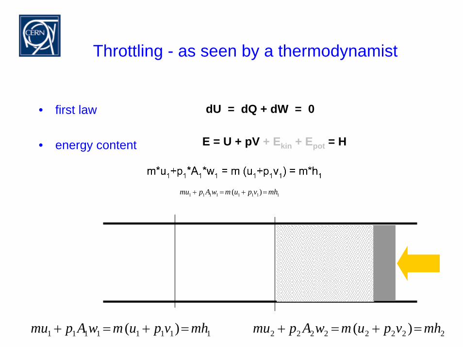
Throttling - as seen by a thermodynamist
dU = dQ + dW = 0• first law
• energy content E = U + pV + Ekin + Epot = H
11111111 )( mhvpumwApmu =+=+
2222222211111111 )()( mhvpumwApmumhvpumwApmu =+=+=+=+
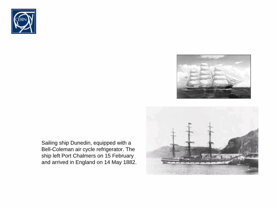
Sailing ship Dunedin, equipped with a Bell-Coleman air cycle refrigerator. The ship left Port Chalmers on 15 February and arrived in England on 14 May 1882.

What is cryogenics?
Time of I. Newton
• J J Becher (1635 - 1682), G.E Stahl (1660 - 1734) I. Newton 1642 - 1727
phlogiston
Heat transferand
insulation
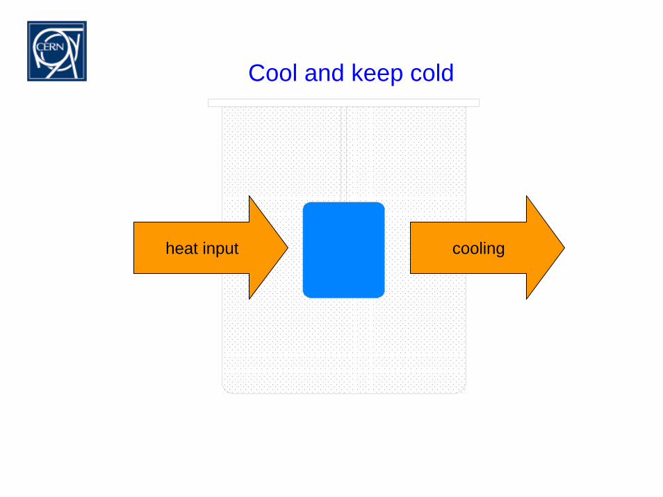
Cool and keep cold
heat input cooling
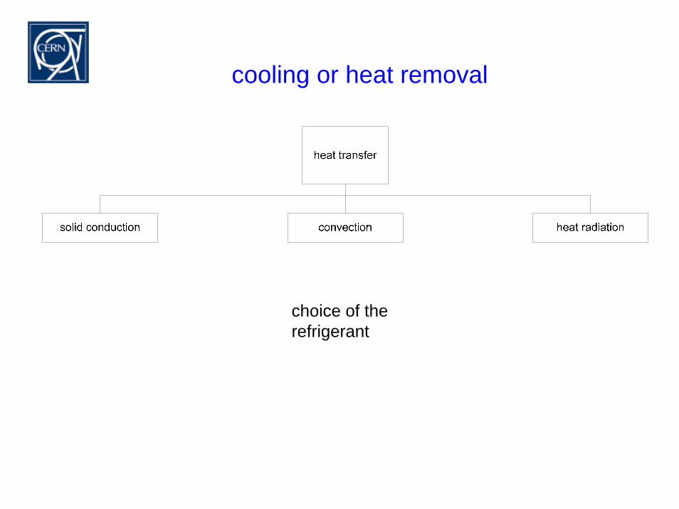
cooling or heat removal
choice of therefrigerant
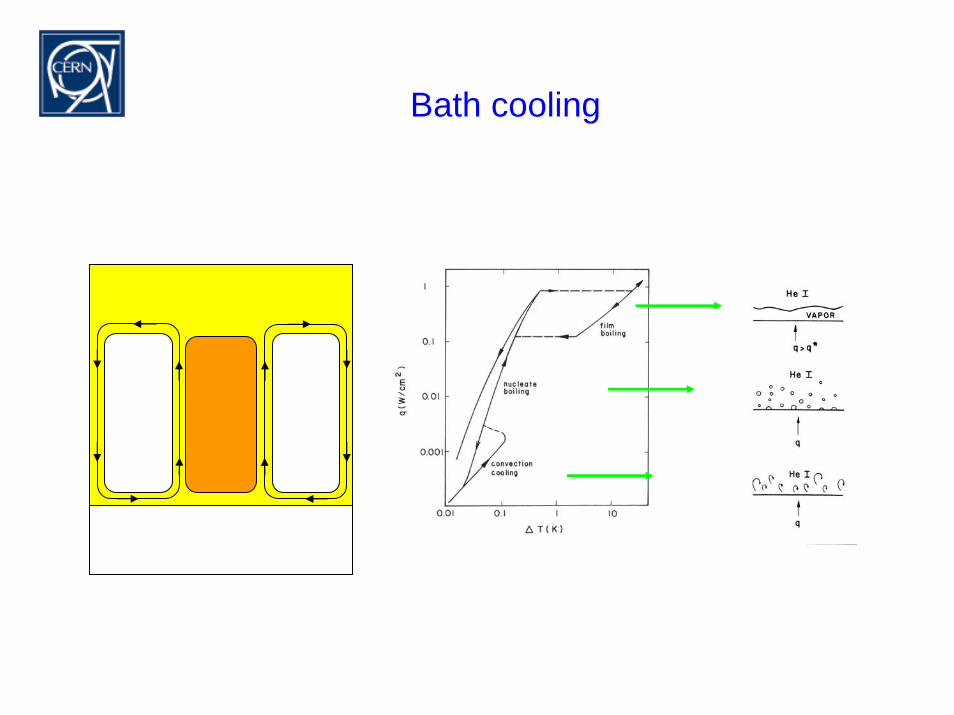
Bath cooling
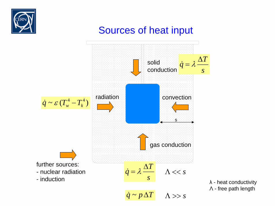
Sources of heat input
radiation convection
gas conduction
solidconduction
further sources:- nuclear radiation- induction
sTq ∆
= λ&
sTq ∆
= λ&
Tpq ∆~&
)(~ 44kw TTq −ε&
s<<Λ
s>>Λ
s
λ - heat conductivityΛ - free path length
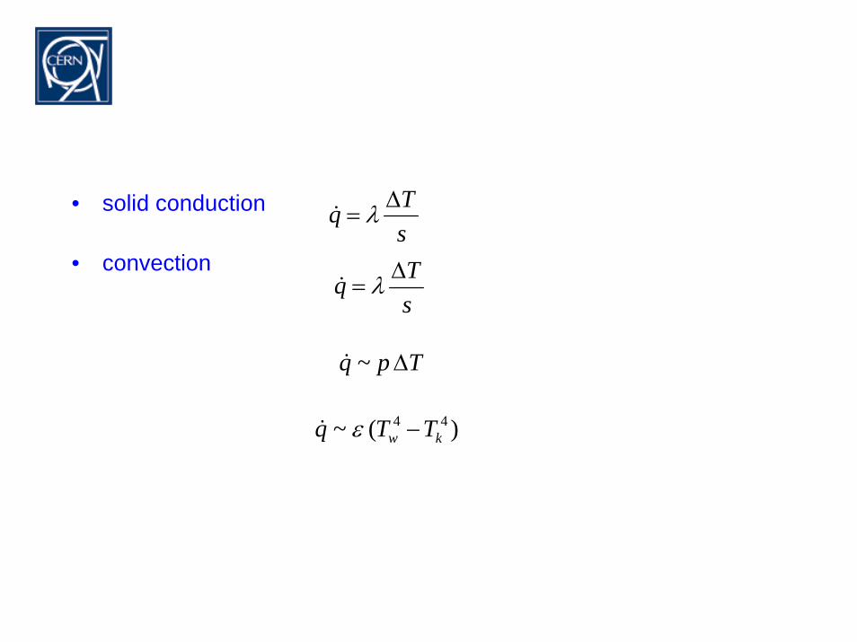
sTq ∆
= λ&• solid conduction
• convection
sTq ∆
= λ&
Tpq ∆~&
)(~ 44kw TTq −ε&
Introduction to Refrigerators
andCryogens
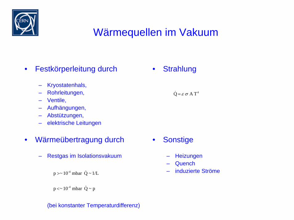
Wärmequellen im Vakuum
• Festkörperleitung durch
– Kryostatenhals, – Rohrleitungen, – Ventile,– Aufhängungen, – Abstützungen,– elektrische Leitungen
• Wärmeübertragung durch
– Restgas im Isolationsvakuum
(bei konstanter Temperaturdifferenz)
• Strahlung
• Sonstige
– Heizungen– Quench– induzierte Ströme
TA Q 4σε=&
p~Qmbar 10~p
1/L~Qmbar 10~p
4-
-4
&
&
<
>